Embed Size (px)
Citation preview

i
MELCOR Computer Code Application Guidance for
Leak Path Factor in Documented Safety Analysis
Final Report
U.S. Department of Energy Office of Environment, Safety and Health
U.S. Department of Energy 1000 Independence Ave., S.W. Washington, DC 20585-2040
May 2004

MELCOR LPF Guidance May 2004 Final Report
ii
INTENTIONALLY BLANK

MELCOR LPF Guidance May 2004 Final Report
iii
Foreword This document provides guidance to Department of Energy (DOE) facility analysts in the use of the MELCOR computer code for supporting Documented Safety Analysis applications. Information is provided herein that supplements information found in the MELCOR documentation provided by the code developer. MELCOR is one of six computer codes designated by DOE’s Office of Environmental, Safety and Health as a toolbox code for safety analysis. Suggestions for corrections or improvements to this document should be addressed to – Chip Lagdon EH-31/GTN Office of Quality Assurance Programs U.S. Department of Energy Washington, D.C. 20585-2040 Phone (301) 903-4218 Email: [email protected]

MELCOR LPF Guidance May 2004 Final Report
iv
INTENTIONALLY BLANK

MELCOR LPF Guidance May 2004 Final Report
v
Revision Status
Page/Section Revision Change
1. Entire Document 1. Final Draft for Review 1. Original Issue
2. Entire Document 2. Final Report 2. Changes due to Reviewer Comments

MELCOR LPF Guidance May 2004 Final Report
vi
INTENTIONALLY BLANK

MELCOR LPF Guidance May 2004 Final Report
vii
Contents Page
1.0 INTRODUCTION.......................................................................................................... 1-1 1.1. Background: Overview Of Toolbox Software in Context of 10 CFR 830 .................. 1-2 1.2. Scope............................................................................................................................ 1-3 1.3. Purpose......................................................................................................................... 1-3 1.4. Applicability ................................................................................................................ 1-3
2.0 SUMMARY DESCRIPTION OF THE MELCOR CODE........................................ 2-1
3.0 APPLICABLE REGIMES IN ACCIDENT ANALYSIS........................................... 3-1
4.0 DEFAULT INPUTS & RECOMMENDATIONS....................................................... 4-1 4.1. Building Nodalization – Volumes and Flow Paths...................................................... 4-1 4.2. Boundary and Initial Conditions.................................................................................. 4-6 4.3. Aerosol Modeling ........................................................................................................ 4-7 4.4. Fire Modeling............................................................................................................. 4-15 4.5. Heat Structures Modeling .......................................................................................... 4-16 4.6. MELCOR Benchmarks.............................................................................................. 4-17
5.0 SPECIAL CONDITIONS FOR USE OF SOFTWARE............................................. 5-1
6.0 SOFTWARE LIMITATIONS ...................................................................................... 6-1 6.1. Outcome of Gap Analysis............................................................................................ 6-1
7.0 SAMPLE CALCULATIONS APPLYING SOFTWARE.......................................... 7-1 7.1. Building Seismic Event with Powder Spill.................................................................. 7-1 7.2. Building Seismic Event with Powder Spill and Exhaust Ventilation Operating ......... 7-9 7.3. Building Seismic Event with Powder Spill and Post Seismic Fire............................ 7-14 7.4. Building Seismic Event with Powder Spill and Post Seismic Fire and Exhaust
Ventilation ................................................................................................................. 7-19 7.5. Building Seismic Event with Multiple Powder Spill................................................. 7-21
8.0 ACRONYMS AND DEFINITIONS............................................................................. 8-1
9.0 REFERENCES............................................................................................................... 9-1

MELCOR LPF Guidance May 2004 Final Report
viii
TABLES Page
Table 2-1. MELCOR Modules................................................................................................. 2-2 Table 4-1. Clearance Dimensions for Standard Steel Doors and Frames ................................ 4-2 Table 4-2. Typical Building Wind Pressure Coefficients ........................................................ 4-6 Table 4-3. ∆P and Absolute Pressure on a Building ................................................................ 4-6 Table 4-4. Oxide Powders Particle Size Distribution............................................................... 4-8 Table 4-4. Triangular Mass Spill Distribution ....................................................................... 4-12 Table 4-5. Rectangular Mass Spill Distribution..................................................................... 4-13 Table 4-6. Typical Fire Input ................................................................................................. 4-15 Table 6-1. Summary of Important Exceptions, Reasoning, and Suggested Remediation ........ 6-3 Table 7-1. Seismic Problem Building Dimensions .................................................................. 7-2 Table 7-2. Seismic Problem Environmental Volumes Pressure............................................... 7-2 Table 7-3. Seismic Problem Volume Connectivity.................................................................. 7-4 Table 7-4. Seismic Problem Ventilation Flows (9.44 m3/s) .................................................. 7-10 Table 7-5. Seismic Problem Ventilation Flows (14.16 m3/s) ................................................ 7-10 Table 7-6. Fire Mass Enthalpy and Energy............................................................................ 7-15 Table 7-7. Seismic Multiple Spill Problem Released Material Distribution Results............. 7-21 Table 7-8. Parametric Study Distribution of Released Material Used ................................... 7-23 Table B-1. Volume Dimensions................................................................................................B-3 Table B-2. Flow Path Dimensions ............................................................................................B-3

MELCOR LPF Guidance May 2004 Final Report
ix
FIGURES Page
Figure 2-1. MELCOR Execution Flowchart 2-5
Figure 4-1. Typical Building Nodalization 4-4
Figure 4-2. Typical Building Nodalization Flow Diagram 4-5
Figure 4-3. Lognormal Particle Diameter Distribution of PuO2 4-9
Figure 4-4. Volume-equivalent Mass Median Particle Diameter Influence on Lognormal Particle Distribution 4-10
Figure 4-5. Volume-equivalent Mass Median Particle Diameter Influence on Lognormal Particle Distribution (Semi-log X-scale) 4-11
Figure 4-6. Triangular Spilled Mass versus Time Distribution 4-12
Figure 4-7. Rectangular Spilled Mass versus Time Distribution 4-13
Figure 4-8. Influence of Released Mass on LPF 4-14
Figure 4-9. Typical Fire Input — Fire Power Versus Time 4-16
Figure 7-1. Seismic Problem — Building Simple Nodalization Model 7-1
Figure 7-2. Seismic Problem — Building Simple Nodalization Flow Diagram 7-3
Figure 7-3. Seismic Problem — Modulating Door Representation (Model of Room Area versus Time) 7-5
Figure 7-4. Seismic Problem Aerosol Material Release Rate in Volume No. 350 7-6
Figure 7-5. Seismic Problem Result — Aerosolized Material in Environmental Volumes 7-7
Figure 7-6. Seismic Problem Result — Total Building LPF 7-8
Figure 7-7. Seismic Problem Result — Material Deposited Inside Building 7-8
Figure 7-8. Building Nodalization for a Seismic Event with Exhaust Ventilation On 7-9
Figure 7-9. Seismic Problem (Ventilation On) —Building Nodalization Flow Diagram 7-11
Figure 7-10. Seismic Problem Result (Ventilation On) —Aerosol Material in Volume Number 900 7-12
Figure 7-11. Seismic Problem Result (Ventilation On) —Aerosol Material Deposited Inside Building 7-12

MELCOR LPF Guidance May 2004 Final Report
x
Figure 7-12. Seismic Problem Result (Ventilation On) —Building LPF (Total ventilation flow of 9.44 m3/s) 7-13
Figure 7-13. Seismic Problem Result (Ventilation On) —Building LPF (Total ventilation flow of 14.16 m3/s) 7-14
Figure 7-14. Fire Problem — Nodalization of Building with a Fire in Volume No. 350 7-15
Figure 7-15. Fire Problem — Fire Power versus Time 7-16
Figure 7-16. Fire Problem Result — Aerosolized Material in Environmental Volumes 7-17
Figure 7-17. Fire Problem Result — Aerosol Material Deposited Inside Building 7-17
Figure 7-18. Fire Problem Result — Total Building LPF 7-18
Figure 7-19. Fire Plus Seismic (Ventilation On) — Aerosol Material in Volume No. 900 7-19
Figure 7-20. Fire Plus Seismic (Ventilation On) — Aerosol Material Deposited Inside Building 7-20
Figure 7-21. Fire Plus Seismic (Ventilation On) — Building LPF (Total ventilation flow 14.16 m3/s) 7-20
Figure 7-22. Seismic Problem With Multiple Spills — Building Nodalization 7-21
Figure 7-23. Seismic Problem With Multiple Spills — Aerosolized Material in Environmental Volumes 7-22
Figure 7-24. Seismic Problem With Multiple Spills — Material Deposited Inside Building7-22
Figure 7-25. Seismic Problem With Multiple Spills — Building LPF 7-23
Figure 7-26. Influence of Released Material on LPF 7-24
Figure B-1. Building Layout Used in Benchmark B-1
Figure B-2. MELCOR Model Block Diagram B-2
Figure B-3. Large Fire Profile B-4
Figure B-4. Small Fire Profile B-5
Figure B-5. Total LPF (Seismic Spill – No ventilation) B-6
Figure B-6. Total LPF (Seismic Spill – With ventilation) B-7
Figure B-7. Total LPF (Spill With Large Fire and Ventilation) B-8

MELCOR LPF Guidance May 2004 Final Report
xi
Figure B-8. Temperature in Volume 150 (Spill With Large Fire and Ventilation) B-9
Figure B-9. Total LPF (Spill with Small Fire – No Ventilation) B-10
Figure B-10. Temperature in Volume 150 (Spill with Small Fire – No Ventilation) B-11

MELCOR LPF Guidance May 2004 Final Report
xii
MELCOR Computer Code Application Guidance for
Leak Path Factor in Documented Safety Analysis
Executive Summary
The Defense Nuclear Facilities Safety Board issued Recommendation 2002-1 on Quality Assurance for Safety-Related Software in September 2002. The Recommendation identified a number of quality assurance issues for software used in the Department of Energy (DOE) facilities for analyzing hazards, and designing and operating controls that prevent or mitigate potential accidents. The development and maintenance of a collection, or “toolbox,” of high-use, Software Quality Assurance (SQA)-compliant safety analysis codes is one of the major commitments contained in the February 28, 2003 Implementation Plan for Recommendation 2002-1 on Quality Assurance for Safety Software at Department of Energy Nuclear Facilities. In time, the DOE safety analysis toolbox will contain a set of appropriately quality-assured, configuration-controlled, safety analysis codes, managed and maintained for DOE-broad safety basis applications. The MELCOR code is one of the designated toolbox codes.
The MELCOR code is likely to require completion of quality assurance improvement measures before meeting current SQA standards. In the interim period before these changes are completed, MELCOR is considered a useful asset in the support of safety basis calculations. To ensure appropriate application of the designated toolbox software, the Implementation Plan has committed to sponsoring a set of code-specific documents to guide informed use of the software, and supplement the available user’s manual information.
The MELCOR guidance report includes the following:
• Description of the software,
• Appropriate regimes and code limitations,
• Various models applicable for the evaluation of the leak path factor (LPF), and
• Several typical sample problems for leak path factor analyses. Use of the information contained here, although not ensuring correct use of MELCOR in all analytical contexts, will minimize potential user errors and further standardize the use of MELCOR in appropriate regimes of applicability. Following the introductory material, this report presents an overview of MELCOR use for Leak Path Factor evaluation. Various examples are given to cover a range of accident conditions.

MELCOR LPF Guidance May 2004 Final Report
xiii
INTENTIONALLY BLANK

MELCOR LPF Guidance May 2004 Final Report
1-1
1.0 INTRODUCTION
In January 2000, the Defense Nuclear Facilities Safety Board (DNFSB) issued Technical Report 25, (TECH-25), Quality Assurance for Safety-Related Software at Department of Energy Defense Nuclear Facilities (DNFSB, 2000). TECH-25 identified issues regarding the state of software quality assurance (SQA) in the Department of Energy (DOE) Complex for software used to make safety analysis decisions and to control safety-related systems. Instances were noted in which computer codes were either inappropriately applied or were executed with incorrect input data. Of particular concern were inconsistencies in the exercise of SQA from site to site, and from facility to facility, and the variability in guidance and training in the appropriate use of accident analysis software.
During the subsequent 2000 to 2002 period, survey information on SQA programs, processes, and procedures was collected as well as the initial elements to a response plan. However, to expedite implementation of corrective actions in this area, the DNFSB issued Recommendation 2002-1, Quality Assurance for Safety-Related Software at Department of Energy Defense Nuclear Facilities, on September 23, 2002. As part of its Recommendation to the DOE, the DNFSB enumerated many of the points noted earlier in TECH-25, but noted specific concerns regarding the quality of the software used to analyze and guide safety-related decisions, the quality of the software used to design or develop safety-related controls, and the proficiency of personnel using the software. DOE has developed a series of actions that address the Board’s concerns, contained in the Implementation Plan for the DNFSB Recommendation, Implementation Plan for Defense Nuclear Facilities Safety Board Recommendation 2002-1. Two of the actions include: (i) identification of a set of accident analysis software that is widely used in the DOE Complex; and, (ii) issuance of code-specific guidance reports on the use of the “toolbox” codes for DOE facility accident analysis, identifying applicable regime in accident analysis, default inputs, and special conditions for use. Safety analysis software for the DOE “toolbox” status was designated by DOE/EH in March 2003. The supporting basis for this designation was provided by a DOE-chartered Safety Analysis Software Group in a technical report entitled, Selection of Computer Codes for DOE Safety Analysis Applications, dated August 2002 (see https://www.hss.doe.gov/deprep/archive/rec/2002-1/NNSACCodes1.pdf), and includes the Version 1.8.5 of MELCOR computer code. The contents of this report are applicable in the interim period until measures are completed to bring MELCOR into compliance with defined SQA standards. The primary objective of the guidance report is to provide information on the use of MELCOR for supporting DOE safety basis accident analysis. Specifically, the purpose this report is to provide guidance on the use of MELCOR for Leak Path Factor analyses. The report contains:

MELCOR LPF Guidance May 2004 Final Report
1-2
• Applicability guidance for Documented Safety Analysis (DSA)-type Leak Path Factor (LPF)
analysis, specifically tailored for DOE safety analysis • Appropriate regimes, recommended configurations • Valid ranges of input parameters consistent with code capability and DOE safety basis
applications when calculating LPF • Modeling approach for various accident types • Typical and default input value recommendations, and • Citations of currently available SQA documentation.. This report is written to guide analysts in efficiently use MELCOR computer code to evaluate the Leak Path Factor for various accident conditions. In this area, this report is intended to complement existing MELCOR user’s documentation. The existing user’s documentation tends to be much broader in coverage of the full range of capabilities of MELCOR and the spectrum of inputs that might be needed depending upon the application. The existing documentation lacks cohesive and targeted guidance for particular applications such as LPF determination for DSA accident analyses. Furthermore, the goal of this document is to identify limitations and vulnerabilities not readily found in documentation from the code developer or published elsewhere. The MELCOR LPF guidance document is written using the following set of sections. This first section contains an introduction and background providing an overview of appropriate software in the context of 10 CFR 830. More information follows on the scope and purpose of this document. The next major section is a summary description of MELCOR. A third section discusses applicable regimes for using MELCOR in performing accident analysis. A discussion on default inputs and input recommendations is provided, emphasizing appropriate inputs for DOE applications. This section is succeeded by a section on models and recommendations. Following this discussion are sections on special conditions for use of the software and software limitations. Several sample cases are then provided, followed by acronyms and definitions, references, and appendices.
1.1. Background: Overview Of Toolbox Software in Context of 10 CFR 830 In the context of 10 CFR 830, the Nuclear Safety Management rule, the six computer codes designated by DOE/EH as toolbox software, may be viewed as appropriate computer software to be applied for support of safety basis documentation. After completion of the minimum required SQA upgrade measures for a toolbox code, the safety analyst would still need to justify the specific application with the code of interest, input parameters, and user assumptions, but many SQA burdens would be reduced from current requirements. The user would need to reference the toolbox code and version, identify compliance with their organization’s SQA requirements and demonstrate that the code is being applied in the proper accident analysis context using appropriate inputs. The SQA pedigree would be sufficiently established for technical review purposes since the code is recognized as toolbox-supported.

MELCOR LPF Guidance May 2004 Final Report
1-3
Only six codes out of more than one hundred software packages applied in the DOE Complex for accident analysis purpose have been designated as “toolbox” codes. Other non-toolbox, dispersion and consequence software can still be applied in the context of support safety basis applications. However, each organization applying this category of software will need to software.
1.2. Scope This document covers use of the MELCOR computer code for the evaluation of the Leak Path Factor for nonreactor nuclear facilities for various accident conditions. It includes a sample facility analyzed for seismic and fire induced release of aerosolized radioactive materials. The MELCOR guidance report includes the following:
• Applicability information for DSA-type analysis, specifically tailored for DOE safety analysis related to LPF calculations
• Code development information and SQA background
• Appropriate regimes and code limitations
• Valid ranges of input parameters consistent with code capability and DOE safety basis applications, and
• Typical and default input value recommendations.
1.3. Purpose The MELCOR code is part of the appropriate collection of software. Software Quality Assurance (SQA) concerns exist. Until MELCOR upgrades are completed so that MELCOR meets current established standards for software, MELCOR can be applied safety under the condition that the guidance contained in this report is followed. Once upgrades are finalized with MELCOR, it will be brought under configuration control and placed in the toolbox. Use of the information contained here, although not ensuring correct use of MELCOR in all analytical contexts, will minimize potential user errors and the likelihood of use outside regimes of applicability.
1.4. Applicability In addition to MELCOR, other software exists for calculating the leak path factor and or analyzing the transport and deposition of hazard material in DOE nuclear facilities under postulated accident conditions. In some cases, manual or electronic spreadsheet calculations can be a preferred alternative to using a computer code for some accident analysis applications for simple geometries involving releases of radiological material. The relative merits of using different software or using a hand calculation for a given application is a judgment that must be made on a case-by-case basis.

MELCOR LPF Guidance May 2004 Final Report
1-4
The U.S. Department of Energy (DOE) has provided guidance and general recommendations in this area through the Accident Phenomenology and Consequence (APAC) Methodology Evaluation Program. As part of this program, the In-Facility Transport Working Group (WG) was established to address issues and evaluate methodologies in the leak path factor and in-facility transport domain. The WG issued a report that identifies and evaluates methodologies and computer codes to support safety basis calculations (Spore, 1996).
The WG report identified MELCOR as the best code for the analysis of in-facility transport when multidimensional effects are not significant. Significant benchmarking has also been performed with MELCOR especially with respect to its aerosol models. Finally as was noted in Section 1, MELCOR has been designated as a toolbox code for safety analysis DSA applications by DOE’s Safety Analysis Software Group.
This report builds upon the APAC work to provide guidance and recommendations that are targeted to the use of MELCOR for leak path factor analysis of complicated flow situations in multi-cell, nuclear facilities. Specifically, the guidance is best suited for:
• Baseline, accident analysis calculations of the leak path factor • Scoping analysis in the initial design of facilities, or backfit modifications of existing
facilities • Emergency management planning for workers, and • Confirmatory calculations for evaluating mitigative and preventive safety controls.

MELCOR LPF Guidance May 2004 Final Report
2-1
2.0 SUMMARY DESCRIPTION OF THE MELCOR CODE
Leak Path Factor analysis can be performed by developing and applying physically realistic modeling utilizing the U. S. Nuclear Regulatory Commission generalized mass transport and thermal-hydraulics computer program MELCOR 1.8.5, (Gauntt, 2000). MELCOR was initially developed at the Sandia National Laboratory under the sponsorship of the USNRC to assess reactor severe accident conditions. Subsequently both NRC and the DOE have sponsored changes to the code. For example, modifications were made to a version of MELCOR to model K reactor severe accidents at the DOE operated Savannah River Site. For the last several years, MELCOR has been used in the DOE complex to model release of radioactive airborne material from non-reactor facilities and structures. The leakage is usually expressed as a fraction of the amount considered available for release and is termed the Leak Path Factor. MELCOR is a fully integrated, engineering-level computer code whose primary purpose is to model the progression of accidents in light water reactor nuclear power plants. A broad spectrum of severe accident phenomena in both boiling and pressurized water reactors is treated in MELCOR in a unified framework. MELCOR estimates fission product source terms and their sensitivities and uncertainties in a variety of applications. The MELCOR code is composed of a number of major modules, or packages, that together model the major systems of a reactor plant and its generally coupled interactions. Many of these models are not required for LPF analyses. Nevertheless, the user should be aware of the existence of the many modules. Reactor plant systems and their response to off-normal or accident conditions include: 1. Thermal-hydraulic response of the primary reactor coolant system, the reactor cavity, the
containment, and the confinement buildings 2. Core uncovering (loss of coolant), fuel heat-up, cladding oxidation, fuel degradation (loss of
rod geometry), and core material melting and relocation 3. Heatup of reactor vessel lower head from relocated fuel materials and the thermal and
mechanical loading and failure of the vessel lower head, and transfer of core materials to the reactor vessel cavity
4. Core-concrete attack and ensuing aerosol generation 5. In-vessel and ex-vessel hydrogen production, transport, and combustion 6. Fission product release (aerosol and vapor), transport, and deposition 7. Behavior of radioactive aerosols in the reactor containment building, including scrubbing in
water pools, and aerosol mechanics in the containment atmosphere such as particle

MELCOR LPF Guidance May 2004 Final Report
2-2
agglomeration and gravitational settling, and the impact of engineered safety features on thermal-hydraulic and radionuclide behavior
The various code packages have been written using a carefully designed modular structure with well-defined interfaces between them. This allows the exchange of complete and consistent information among them so that all phenomena are explicitly coupled at every step. MELCOR modeling is general and flexible, making use of a “control volume” approach in describing the plant system. No specific nodalization of a system is forced on the user, which allows a choice of the degree of detail appropriate to the task at hand. The various modules (or packages) available in MELCOR are listed in Table 2-1 to give a good understanding of the full capabilities of the computer code. Table 2-1. MELCOR Modules
MELCOR Modules (or Packages) Available
Module Name
Description
BH Bottom Head. This model was developed by the Oak Ridge National Laboratory, and is an alternative to the lower plenum modeling in COR
BUR Burn (Combustion) of Gases. Compares conditions within control volumes against criteria for deflagrations and detonations. Initiates and propagates deflagrations involving hydrogen and carbon monoxide. Calculates burn completeness and flame speed
CAV Core-concrete Interactions. CORCON-MOD3 with enhanced sensitivity analysis and multi-cavity capabilities
CF Control Functions. Evaluates user-specified “control functions” and applies them to define or control various aspects of the computation such as opening and closing of valves; controlling plot, edit, and restart frequencies; defining new plot variables, etc.
COR Core Behavior. Evaluates the behavior of the fuel and other core and lower plenum structures including heatup, candling, flow blockages, debris formation and relocation, bottom head failure, and release of core material to containment
CVH Control Volume Hydrodynamics. In conjunction with the FL package, evaluates mass and energy flows between control volumes

MELCOR LPF Guidance May 2004 Final Report
2-3
MELCOR Modules (or Packages) Available
Module Name
Description
CVT CVT - Control Volume Thermodynamics. Evaluates the thermodynamic state within each control volume for the CVH package. No users’ guide is written for this package since no user input is required. However, a reference manual is written.
DCH Decay Heat. Used by other packages to evaluate decay heat power associated with radionuclide decay
EDF External Data Files. Controls the reading and writing of large external data files, in close interface with the Control Function and Transfer Process packages
EOS Equation of State. The CVT, H2O, and NCG packages are stored as one block of code under this name
ESF Engineered Safety Features. Models the thermal-hydraulics of engineered safety features that cannot be effectively modeled by building appropriate components or systems using the CVH, FL, HS, and CF packages. Currently, only the fan cooler model is included in ESF; the containment sprays are modeled in the SPR package
EXEC Executive Package. Controls execution of MELGEN and MELCOR
FDI Fuel Dispersal Interactions. Models ex-vessel debris relocation, heat transfer, and oxidation due to fuel-coolant interactions and high pressure melt ejection
FL Flow Paths. Models, in conjunction with the CVH package, the flow rates of gases and liquid water through the flow paths that connect control volumes
H2O Water Properties. Evaluates the water properties based on the Keenan and Keyes equation of state extended to high temperatures using the JANAF data. This set of routines is in the “EOS” code package. No user input is required
HS Heat Structures. Models the thermal response of heat structures and mass and heat transfer between heat structures and control volume pools and atmospheres. Treats conduction, condensation, convection, and radiation, as well as degassing of unlined concrete

MELCOR LPF Guidance May 2004 Final Report
2-4
MELCOR Modules (or Packages) Available
Module Name
Description
MP Material Properties. Evaluates the physical properties of materials for other packages except for common steam and noncondensible gas properties (see H2O and NCG)
NCG NonCondensible Gas Equation of State. Evaluates the properties of noncondensible gas mixtures using an equation of state based on the JANAF data. This set of routines is in the “EOS” code package
PAR Passive Autocatalytic Hydrogen Recombiner. Includes general models for modeling hydrogen recombiners in the containment rooms
PROG Part of MELGEN/MELCOR Executive package separated for computer library and link purposes
RN Radionuclide Behavior. Models radionuclide releases, aerosol and fission product vapor behavior, transport through flow paths, and removal due to ESFs. Allows for simplified chemistry
SPR Sprays. Models the mass and heat transfer rates between spray droplets and control volumes
TF Tabular Functions. Evaluates user-selected “tabular functions” to define or control various aspects of the computation such as mass and energy sources; integral decay heat; plot, edit, and restart frequencies, etc.
TP Transfer Process. Controls the transfer of core debris between various packages and the associated transfer of radionuclides within the RN package. In order to transfer core material between packages, some TP input is required, and is described in the COR, FDI, and CAV package Users’ Guides
UTIL Utility Package. Contains various utilities employed by the rest of the code.
All the modules described in Table 2-1 above are fully documented in the MELCOR documentation, (Gauntt, 2000). The assessments made on the various models are also documented and are also cited in (Gauntt, 2000). The user is encouraged to review their documentation to have a better understanding of the full capabilities of MELCOR. Although this computer code was developed to model the progression of accidents in light water reactor nuclear power plants, the modeling capabilities of MELCOR are sufficiently flexible that

MELCOR LPF Guidance May 2004 Final Report
2-5
it can be applied to the analysis of nonreactor problems. MELCOR was originally conceived as a Probabilistic Risk Assessment code. The code is now viewed as a primary tool for source term calculations. When performing LPF studies for nonreactor nuclear facilities the modules used are reduced (through input specification – the code activates modules based on the input card identification field) to those which will enable the modeling of the release and transport of aerosolized materials. The most common modules used for Leak Path Factor analyses are: • Executive Package (EXEC) • NonCondensible Gas Package (NCG) • Control Volume Hydrodynamics Package (CVH) • Flow Path Package (FL) Appendix A. Heat Structures Package (HS) • RadioNuclide Package (RN) • Control Function Package (CF) • Tabular Function Package (TF) MELCOR is available for the UNIX workstation platform as well as the PC platform. The execution of MELCOR on a PC is very efficient and user friendly. While either platform may be used, simply because of ease of use the latter is recommended. Figure 2-1 depicts a basic flowchart showing the steps required to successfully execute MELCOR.
MELGEN MELCOR
MELGENUser Input
MELGENOutput
Diagnostic
RestartFile
MELCORUser Input
MELCOROutput
MessageDiagnostic
Extended DiagnosticUser Defined
Plot File
ReleaseFile MACCS
ConsequenceAnalysis
HISPLTM
XYMEL
PTFREAD
Plot Software
Figure 2-1. MELCOR Execution Flowchart

MELCOR LPF Guidance May 2004 Final Report
2-6
The user prepares an input data file which includes data for MELGEN and MELCOR. After running the two executables (MELGEN and MELCOR), all the output data files are created including a binary plot file (FILE.PTF) which can be used in one of three software packages provided to visualize the output graphically. The plotting software distributed with MELCOR includes HISPLTM, XYMEL, and PTFREAD. The first package, HISPLTM, is an excellent plotting software package; however, it requires additional inputs (pre-planning by the user) in the main MELGEN/MELCOR input file to generate plots. The two packages XYMEL and PTDREAD work very well and are recommended since they do not require any special inputs (as required for HISPLTM) in the main input file for MELGEN/MELCOR. These two latter packages work directly with the binary plot file generated by MELCOR. They provide for easy access to the various arrays the user desires to plot. XYMEL software is equipped with a user-friendly interface and it allows the user to generate high quality plots via the XYMEL interface or by exporting that array to MS Excel. PTFREAD is a MS Excel add-in (.XLA file) which is very simple to use and it can generate plots with the simplicity of a MS Excel interface. The entire set of MELCOR documentation and additional information is available at the Sandia National Laboratory MELCOR website: http://melcor.sandia.gov/ .

MELCOR LPF Guidance May 2004 Final Report
3-1
3.0 APPLICABLE REGIMES IN ACCIDENT ANALYSIS
In accident analysis, the evaluation of the source term is an important step to assess the evaluation of the radiological consequences. The airborne source term is generally estimated using a five-component linear equation as reported in (DOE, 2002): Source Term = MAR x DR x ARF x RF x LPF Where: MAR = Material-at-risk (curies or kg) DR = Damage Ratio ARF = Airborne Release Fraction RF = Respirable Fraction LPF = Leak Path Factor A detailed discussion of the use of this formula in accident analyses is given in the MACCS guidance document and will not be repeated here, (DOE, 2003). See this guide for further detail. With reference to a nonreactor nuclear facility (e.g., a building where forcing conditions could initiate releases of aerosolized radioactive materials), the LPF could be a critical component in the source term equation given above. The Leak Path Factor can be defined as the fraction of airborne radioactive material released, due to a forcing condition, as respirable particulate within the building that escapes via available pathways to the outside environment. The MELCOR computer code is used to effectively evaluate the Leak Path Factor (LPF) component of the source term formula given above in mitigated design basis accident calculations as prescribed in DOE Std 3009 Rev 2, (DOE, 2002). For unmitigated analyses an LPF value of 1.0 is required by DOE Std. 3009.

MELCOR LPF Guidance May 2004 Final Report
4-1
4.0 DEFAULT INPUTS & RECOMMENDATIONS
The analysis of the Leak Path Factor for a facility (e.g., building) requires several front-end steps to be taken to assess the boundary of the problem as well as the modeling approximation approach. When a facility (building) has to be analyzed it is important to gather the facility structural and architectural drawings. This first step is essential to model the facility with MELCOR. MELCOR computer code uses a control volume approach, thus the facility (building) must be subdivided into control volumes (cells) connected by flow paths (flow junctions). Depending on the type of accident condition, the facility is nodalized in different manners to properly model the event. It is recommended to perform benchmark calculations to facility-specific operational test data when available to add confidence to the MELCOR analysis results.
4.1. Building Nodalization – Volumes and Flow Paths In the case of a seismic-induced release, it is important to assess which structures within the facility will withstand the seismic event (i.e., walls, ceilings, etc.). When this assessment is made (e.g., by reviewing the structural analyses or discussing the subject matter with the structural engineering staff) the facility can be subdivided into cells formed by structures connected by flow paths. Any non-seismic (not seismically qualified) structure is not credited in the model (unless survival of the structure would increase the LPF). One important aspect of this activity is to determine if the seismic event created penetrating cracks (or flow paths) though or around the qualified structures. This is important since these cracks provide a pathway for the released material to migrate to the outside environment. Furthermore it is of importance to evaluate possible pathways leading to the outside environment related to building penetrations (piping, ventilation ducts, electrical conduits, etc.). The analyst must use good judgment in creating the various control volumes to assemble the facility nodalization model. It is recommended that the analyst keep the volumes within the same order of magnitude when possible. This helps by decreasing computational time. Very small volumes combined with larger volumes will increase the computational time since the small volumes will control the time-step advancement. If necessary, uniformity in nodalization can be achieved by combining smaller volumes. When nodalizing there is no specific rule to follow, the process is based on judgment acquired with experience. As a starting point for typical nodalization, Appendices C through G include input files demonstrating nodalization schemes that can act to steer the user in the correct direction.
MELCOR LPF Guidance May 2004 Final Report
4-2
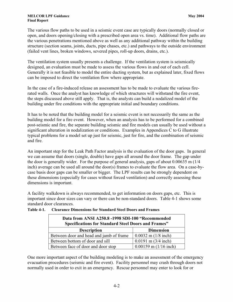
The various flow paths to be used in a seismic event case are typically doors (normally closed or open, and doors opening/closing with a prescribed open area vs. time). Additional flow paths are the various penetrations mentioned above as well as any additional pathway within the building structure (section seams, joints, ducts, pipe chases, etc.) and pathways to the outside environment (failed vent lines, broken windows, severed pipes, roll-up doors, drains, etc.). The ventilation system usually presents a challenge. If the ventilation system is seismically designed, an evaluation must be made to assess the various flows in and out of each cell. Generally it is not feasible to model the entire ducting system, but as explained later, fixed flows can be imposed to direct the ventilation flow where appropriate. In the case of a fire-induced release an assessment has to be made to evaluate the various fire-rated walls. Once the analyst has knowledge of which structures will withstand the fire event, the steps discussed above still apply. That is, the analysts can build a nodalized model of the building under fire conditions with the appropriate initial and boundary conditions. It has to be noted that the building model for a seismic event is not necessarily the same as the building model for a fire event. However, when an analysis has to be performed for a combined post-seismic and fire, the separate building seismic and fire models can usually be used without a significant alteration in nodalization or conditions. Examples in Appendices C to G illustrate typical problems for a model set up just for seismic, just for fire, and the combination of seismic and fire. An important step for the Leak Path Factor analysis is the evaluation of the door gaps. In general we can assume that doors (single, double) have gaps all around the door frame. The gap under the door is generally wider. For the purpose of general analysis, gaps of about 0.00635 m (1/4 inch) average can be used all around the door(s) frames to evaluate the flow area. On a case-by-case basis door gaps can be smaller or bigger. The LPF results can be strongly dependent on these dimensions (especially for cases without forced ventilation) and correctly assessing these dimensions is important. A facility walkdown is always recommended, to get information on doors gaps, etc. This is important since door sizes can vary or there can be non-standard doors. Table 4-1 shows some standard door clearances. Table 4-1. Clearance Dimensions for Standard Steel Doors and Frames
Data from ANSI A250.8 -1998 SDI-100 “Recommended Specifications for Standard Steel Doors and Frames”
Description Dimension Between door and head and jamb of frame 0.0032 m (1/8 inch) Between bottom of door and sill 0.0191 m (3/4 inch) Between face of door and door stop 0.00159 m (1/16 inch)
One more important aspect of the building modeling is to make an assessment of the emergency evacuation procedures (seismic and fire event). Facility personnel may crash through doors not normally used in order to exit in an emergency. Rescue personnel may enter to look for or

MELCOR LPF Guidance May 2004 Final Report
4-3
rescue injured individuals. Fire fighters may enter through non-standard doorways, and may drag hoses, or perform other emergency operations that change the flow paths available in the building. This assessment will enable the analyst to establish time-dependent operation of doors as input into the MELCOR analysis. This is critical for all the doors leading to the outside of the building. It is not uncommon, to find that the calculated LPF is dominated by the opening of a door if only for a short time. The modeling of the environmental volumes is also important since these volumes will be used to compute the amount of aerosolized material escaped from the building enclosure, thus yielding the Leak Path Factor. The analyst can create as many environmental volumes as necessary. This volumes (cells) act as sources and sinks for the MELCOR analysis, thus they need to be large enough to maintain their environmental properties constant (e.g., pressure, temperature). It is generally recommended to set an environmental volume at each side of the building to input the appropriate pressure condition as dictated by the local wind. Additional environmental volumes can be set to model filtration systems, ventilation supply, or to monitor independently LPF contributions from different pathways to the outside environment. It is recommended large environmental volumes be used. A volume of 1.0E+10 m3 is adequate. Figure 4-1 shows a sketch outlining a typical building nodalization suitable for MELCOR analysis.

MELCOR LPF Guidance May 2004 Final Report
4-4
Volume 100
Volume 300
Volume 150 Volume 200
Volume 250
Volume 350
Volume 450
Volume 400
Volume 600 North Env. Volume
Volume 800 South Env. Volume
Volume500
WestEnv.
Volume
Volume700EastEnv.
Volume
Volume 900 Building Top Environment
From Various Building Volumes
Figure 4-1. Typical Building Nodalization
The typical sketch depicted in Figure 4-1 will be useful when the Heat Structure module (HS) is used since it allows the analyst to easily associate the various heat structures for adjacent volumes when the heat transfer is modeled between building cells. The analyst can also translate the sketch given in Figure 4-1 above into a basic building flow diagram to ease the various steps required to complete the MECOR flow modeling of the building. Figure 4-2 shows a simple translation of the sketch given above into an effective flow model diagram to help the analyst in visualizing all the flow paths in a simpler representation.

MELCOR LPF Guidance May 2004 Final Report
4-5
V100
V300
V150 V200
V350 V400
V450
V250
V500West
V600North
V800South
V700East
V900Building Top
Figure 4-2. Typical Building Nodalization Flow Diagram When two volumes (cells) are connected via a flow path like a pipe chase, or a long penetration (pipe-like), or any combination of small adjacent volumes, follow the instructions of the user’s guide. Specifically, these flow paths should be lumped together into a single junction. MELCOR has a facility within the Flow Path Module (FL) that allows the user to model these flow paths with the piping segment input parameters.

MELCOR LPF Guidance May 2004 Final Report
4-6
4.2. Boundary and Initial Conditions The equivalent wind pressure and temperature to be applied to the environmental volumes (boundary volumes) can be readily calculated. The analyst must have knowledge of the site meteorology. The parameters required are the wind speed and wind direction (the recommended wind speed is the same as used in the consequence analysis to maintain consistency). Once the wind speed, direction, and environmental temperatures are available, it is possible to evaluate the equivalent wind pressure to be applied to the environmental volumes. The local air pressure due to wind condition is given by, (ASHRAE, 1977):
2
2vcP pρ=∆
where: c p = Pressure coefficient ρ = Local air density
ν = Wind speed Assuming a value for the wind speed of 2.24 m/s (5 mph), and using a pressure coefficient for a normal building from, (ASHRAE, 1977): Table 4-2. Typical Building Wind Pressure Coefficients
Wind Pressure Coefficients Upwind Pressure Coefficient 0.7 Downwind Pressure Coefficient -0.4 Side and Top of Building -0.35
Using the above wind pressure coefficients and an assumed environmental volume temperature of 294.26 K (70 °F), and local air density of 1.2 kg/m3, the resulting wind pressure is shown in Table 4-3. Table 4-3. ∆P and Absolute Pressure on a Building
∆P and Absolute Pressure for the Environmental Volumes—Normal Atmospheric Pressure set at 101352.9 Pa (14.7 psia), Wind speed 2.24 m/sec ∆P
Pa Absolute Pressure1
Pa Upwind Side of Building 2.10 101355.00 Downwind Side of Building -1.2 101351.69 Side and Top of Building -1.051 101351.85
1 Note that the 14.7 psia atmospheric pressure is an approximation and the user should use the site specific pressure

MELCOR LPF Guidance May 2004 Final Report
4-7
The absolute pressures and the reference temperature of 294.26 K (70 °F) are used as input in the environmental volumes initial conditions. The values of the pressures given in Table 4-3 show that the actual pressure differentials across the building due to wind condition are very small, but large enough to promote the transport of aerosolized material within the building and finally to the outside environment. These pressures must be calculated on a case-by-case basis, and analyses should be performed by rotating the wind direction through the boundary volumes to assess the bounding LPF.
4.3. Aerosol Modeling The MELCOR aerosol input to evaluate a Leak Path Factor is critical. The aerosol dynamics algorithms included in MELCOR are robust, however the analyst has to properly identify inputs to yield a consistent solution. It is very important to handle this part of the MELCOR input extremely carefully. In many DOE facilities the major player is Pu oxide. For this particular material, when in a powder form, there is good information available for input into a MELCOR analysis. For other materials, parametric studies and various assessments may be required to analyze a leak path factor. The MELCOR computer code input requires a distribution of aerosolized particles. The most-likely distribution is a lognormal since actual particle size typically extends through several orders of magnitude. The lognormal distribution of aerosolized particles used by MELCOR (Probability Density Function, PDF) is
)(ln
)/(ln21
2
2
)ln( 21 σ
σπ
mp dd
p
ed
PDF−
=
Where: dp is the distributed variable particle diameter, dm is the volume-equivalent mass median particle diameter, and σ is the geometric standard deviation When dealing with PuO2 powders some experimental data are available from (Sutter, 1981). Table 4-4 reports an experimentally gained distribution from the above reference, which is specific to free fall spill in static air and it could represent a distribution in a seismic event.

MELCOR LPF Guidance May 2004 Final Report
4-8
Table 4-4. Oxide Powders Particle Size Distribution
Oxide Powders Particle Size Distribution
Spill in Static Air Weight percent airborne 0.03% median (equivalent to ARF) Geometric Standard deviation = 2 (lognormal distribution) Particle size median = 8 µm (Aerodynamic Equivalent Diameter (AED))
Particle Diameter
Range µm AED
Particle Diameter Range µm
Fraction in Range
Cumulative Fraction
0.0 0.1 0.00 0.03 0.001 0.001 0.1 1.0 0.03 0.30 0.064 0.065 1.0 3.0 0.30 0.89 0.165 0.230 3.0 10.0 0.89 2.95 0.330 0.560 10.0 70.0 2.95 20.68 0.360 0.920 70.0 200.0 20.68 59.08 0.040 0.960 200.0 1000.0 59.08 295.40 0.030 0.990
> 1000.0 > 295.40 0.01 1.00 With the data given in Table 4-4 and using a theoretical density for the PuO2 of 11.46E+3 kg/m3, (CRC, 1986), the following discussion on the Aerodynamic Equivalent Diameter is given:
The aerodynamic equivalent diameter (AED) to be considered in the respirable range is ≤ 10 µm, and the DAED specifically refers to an equivalent sphere with a density of 1 g/cm3. The particle Geometric Diameter Dg is related to the DAED by the following equation described in (DOE, 2002):
[ ] [ ]( ) αρ // 5.0,,
5.0aCeCpgAED CCDD =
Where: ρp = Particle density (g/cm3) CC,e = Cunningham slip factor corresponding to volume equivalent diameter CC,a = Cunningham slip factor corresponding to the aerodynamic equivalent
diameter, and α = Aerodynamic shape factor.

MELCOR LPF Guidance May 2004 Final Report
4-9
The Cunningham slip factor is related to the potential for particle impact with the mean free path of air molecules. Above the sub-micron size range, all particles impact with air molecules, and the ratio of Cunningham factors can be ignored. The aerodynamic shape factor is not typically known and is assumed to be 1. Therefore, DAED may be estimated from Dg by simply multiplying Dg by the square root of the particle density. The maximum Aerodynamic Equivalent Diameter of 10 µm for Plutonium Oxide with a density of 11.46 g/cm3 corresponds to a maximum geometric diameter of approximately 3 µm. With this information and the PDF function given above, a lognormal distribution can be built. Maximum aerosol particle diameter = 3 µm Minimum aerosol particle diameter = 0.01 µm (this is an arbitrary minimum) Volume-equivalent mass median particle diameter = 2.3 µm (8 µm AED) Geometric standard deviation of the particle size distribution = 2 (95%) With these data approximately 63% of the airborne particles distribution is smaller than 3 µm (10 µm Aerodynamic Equivalent Diameter) and are respirable. Figure 4-3 shows the distribution as discussed above to be used as an initial aerosol distribution.
5´10-7 1´10-6 1.5 ´10-6 2´10-6 2.5 ´10-6 3´10-6
Particle Diameter , m
0
50000
100000
150000
200000
250000
300000
ytilibaborPytisneD
noitcnuF
Figure 4-3. Lognormal Particle Diameter Distribution of PuO2
Note that the above distribution of aerosolized powders used as MELCOR input is all respirable (maximum aerosol particle diameter ≤ 10 µm AED). This is important since when combining the calculated LPF value in the source term five-component equation it results in consistency among the terms (the LPF is a multiplier of ARF x RF which is already all respirable).

MELCOR LPF Guidance May 2004 Final Report
4-10
If the analyst uses a distribution that extends beyond the 10 µm AED, the RF will be double counted, thus making the source term inconsistent. Other experimental distributions for various events can be found in (Sutter, 1983, SNL, 1983, and Mishima, 1973). If there is no experimental information available for the aerosolized material, parametric studies to assess possible distributions are recommended. For conservatism, a material density of 1 g/cm3 could be used. With this density the maximum respirable particle diameter is 10 µm geometric or 10 µm AED. From this a distribution can be built, but the volume-equivalent mass median particle diameter is not known. Figure 4-4 shows how the volume-equivalent mass median particle diameter changes the distribution.
0 2´ 10-6 4´ 10-6 6´ 10-6 8´ 10-6 0.00001Particle Diameter , m
0
250000
500000
750000
1´ 106
1.25 ´ 106
1.5 ´ 106
1.75 ´ 106
ytilibaborPytisneD
noitcnuF
Figure 4-4. Volume-equivalent Mass Median Particle Diameter Influence on Lognormal Particle Distribution
This figure shows how the peak of the distribution shifts to the right for an increase of the volume-equivalent mass median particle diameter. The higher peak corresponds to a 0.5 µm volume-equivalent mass median particle diameter, and the lower peak to 5.0 µm. The intermediate values correspond to 1.0, 2.0, 3.0, and 4.0 µm respectively.

MELCOR LPF Guidance May 2004 Final Report
4-11
If a small volume-equivalent mass median particle diameter is chosen the LPF value will increase. It is evident that the determination of an appropriate volume-equivalent mass median particle diameter is quite complicated, and further studies would be required to properly justify an appropriate assumed analysis value of the volume-equivalent mass median particle diameter. Figure 4-5 reports Figure 4-4 curves in semi-log scale to better render the curves.
1. ´ 10- 8 5. ´ 10- 8 1. ´ 10- 7 5. ´ 10- 7 1. ´ 10- 6 5. ´ 10- 6 0.00001Particle Diameter , m
0
250000
500000
750000
1´ 106
1.25 ´ 106
1.5 ´ 106
1.75 ´ 106
ytilibaborPytisneD
noitcnuF
Figure 4-5. Volume-equivalent Mass Median Particle Diameter Influence on Lognormal Particle Distribution (Semi-log X-scale) An additional MELCOR input is the amount of aerosolized material released in the facility (building). This input can be set as a tabular function (TF module) were the amount of material (kg) is input versus time. Generally the analysis of the LPF can be performed prior to the establishment of the magnitude of the source term (MAR x DR x ARF x RF). That is, the aerosolized material released can be set conveniently to a unit weight (1.0 kg, or 1.0 g). This is a convenient way to easily express the LPF as a fraction of the released material, thus generalizing its definition to any amount of material actually released inside the facility. A typical MELCOR input could be a triangular or rectangular normalized distribution as shown in the following Tables and Figures.

MELCOR LPF Guidance May 2004 Final Report
4-12
Table 4-4. Triangular Mass Spill Distribution
Triangular Mass Spill Distribution Time
s Spilled Mass
kg 0.0 0.0 5.0 0.0 6.0 1.0 7.0 0.0 10.0 0.0
0
0.2
0.4
0.6
0.8
1
1.2
0 1 2 3 4 5 6 7 8 9 10
Time (s)
Spill
ed M
ass
(kg)
Figure 4-6. Triangular Spilled Mass versus Time Distribution
MELCOR LPF Guidance May 2004 Final Report
4-13
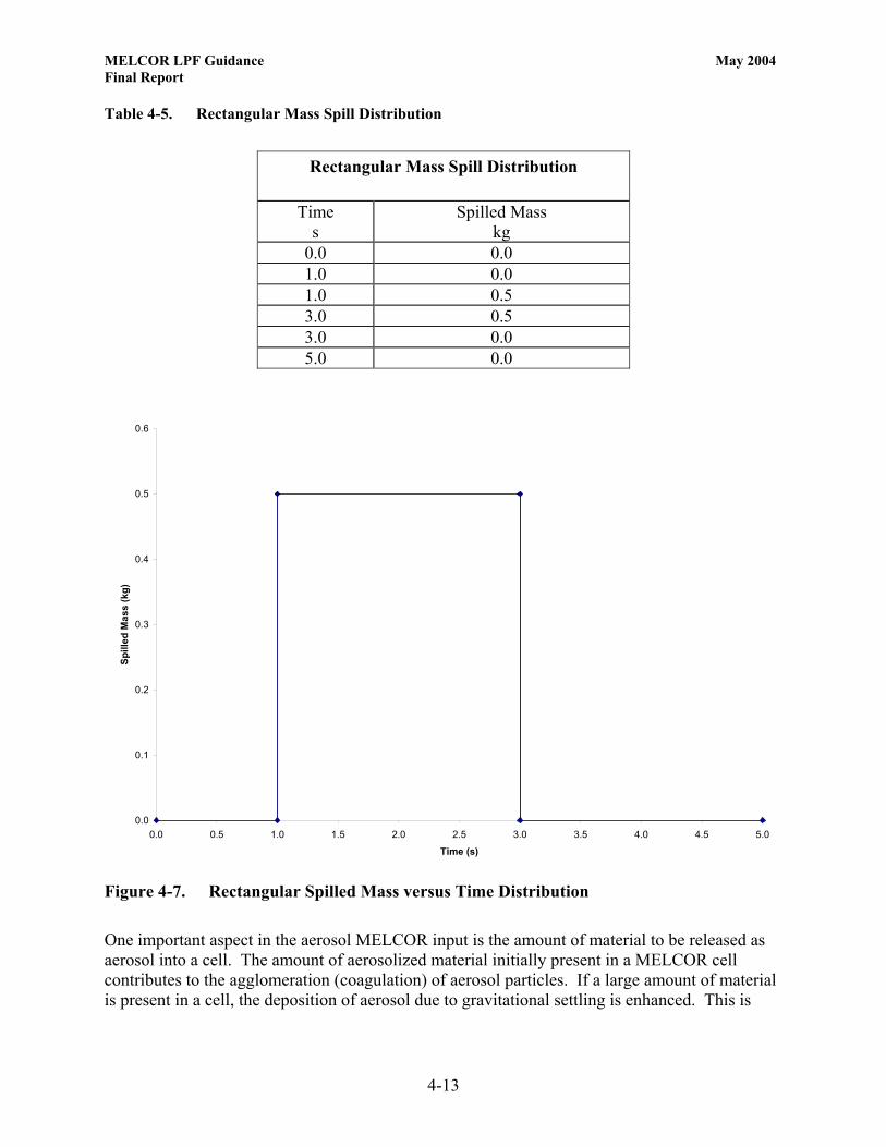
Table 4-5. Rectangular Mass Spill Distribution
Rectangular Mass Spill Distribution
Time
s Spilled Mass
kg 0.0 0.0 1.0 0.0 1.0 0.5 3.0 0.5 3.0 0.0 5.0 0.0
0.0
0.1
0.2
0.3
0.4
0.5
0.6
0.0 0.5 1.0 1.5 2.0 2.5 3.0 3.5 4.0 4.5 5.0
Time (s)
Spill
ed M
ass
(kg)
Figure 4-7. Rectangular Spilled Mass versus Time Distribution One important aspect in the aerosol MELCOR input is the amount of material to be released as aerosol into a cell. The amount of aerosolized material initially present in a MELCOR cell contributes to the agglomeration (coagulation) of aerosol particles. If a large amount of material is present in a cell, the deposition of aerosol due to gravitational settling is enhanced. This is

MELCOR LPF Guidance May 2004 Final Report
4-14
important when the analyst does not know a priori the source term, and consequently, the LPF analysis must be performed with a nominal release of an aerosolized mass (1.0 kg, 1.0 g). Figure 4-8 shows how the LPF value for a seismic case (aerosol released in static air) varies with increasing released masses; figure from (Polizzi, 2000), analysis performed using CONTAIN 2.0 computer code, (Murata, 1977).
0.50
0.60
0.70
0.80
0.90
1.00
1.10
0.001 0.01 0.1 1Spilled Mass of PuO2 (kg)
LPF %
Figure 4-8. Influence of Released Mass on LPF This figure is significant and the analyst should perform a similar sensitivity analysis for each unique LPF evaluation. The results given above cannot be generalized since the magnitude of the LPF variation with the released mass is specific to the initiating event, the forcing condition, etc. (e.g., in the case of a fire initiator, the variation of LPF with mass is most likely insignificant). Unit mass releases are convenient and can be applied as already stated when the source term is not known. However, because of the mass effect indicated in Figure 4-8, if the analyst knows the actual source term injected into a volume, it is recommended the actual value be used. In this situation with releases in multiple cells are taking place, and the actual source term in not yet available at the time of the LPF analysis, it is even more important to perform parametric studies. The interaction between initial source term in cells, flow between cells, and other phenomena may not be intuitive. Within the range of credibility, the user should vary the amount of release in various cells to assure the problem is fully understood, (Polizzi, 2002).

MELCOR LPF Guidance May 2004 Final Report
4-15
4.4. Fire Modeling
Melcor cannot explicitly model the physics of a fire. A fire can be approximately modeled in MELCOR by simply adding mass and energy into a cell(s). Adding energy to the systemgenerates pressure and temperature in the cell(s), which in turn acts as a forcing condition causing leakage of the aerosolized mass present in the cell(s). The fire modeling is accomplished by using a combination of MELCOR Control Functions (CF) and Tabular Functions (TF) modules which will enable the analyst to input the fire model parameter in a tabular form. A recommended approach to use when modeling a fire is to add into a cell(s) a rated mass of material such as water vapor or other gas at a rated enthalpy. (ie.g., add minimal mass at fictionally high but properly accounted for enthalpy) In this way, the mass can be minimized and the product of the two rated entities becomes the desired energy input into the system. If the intent is to input a fire burning at 1.0 Mw for 30 minutes, Table 4-6 shows the rated mass and enthalpy to generate the fire. Table 4-6. Typical Fire Input
Typical Fire Input
Time Mass Enthalpy Energy s kg/s J/kg W
0.0 0.0 0.0 0.0 300.0 0.0 0.0 0.0 600.0 0.001 1.0E+9 1.0E+6 2400.0 0.001 1.0E+9 1.0E+6 2700.0 0.0 0.0 0.0 5000.0 0.0 0.0 0.0
Figure 4-9 shows the typical fire as given in Table 4-6. The correct intensity of the fire and duration will be dependent upon a specific fire analysis. Generally, the more intense the fire, the higher the LPF, and the longer duration the fire, the higher the LPF. However, this is not always true. The analysts should run parametric studies to assess the influence of the varying inputs to understand the specific problem and determine the appropriate LPF.

MELCOR LPF Guidance May 2004 Final Report
4-16
0
0.2
0.4
0.6
0.8
1
1.2
0 500 1000 1500 2000 2500 3000 3500 4000
Time (s)
Fire
Pow
er (M
W)
Figure 4-9. Typical Fire Input — Fire Power Versus Time
As mentioned above, MELCOR does not model the physics of the fire event, but uses an energy input to simulate the fire energy addition into a cell (volume). The actual fire analysis can produce the data required to model the fire. The fire analysis could produce a temperature profile vs. time in the room; the analysts can try to reproduce that profile by running MELCOR, predicting an energy input into the cell and then adjusting until the temperature profile is similar to the one originally calculated by the actual fire analysis. It has to be noted that instead of using the method mentioned above, the analyst could use the potential energy due to the combustible material. This will generate unrealistically high temperature in the fire cells, but it should be conservative. During the combustion process for most of the fires encountered in accident analysis, the production of combustion gases can be neglected. The dominant mechanism to transport aerosols out of the fire cell are the convective flows which are driven by density gradients in the fire compartment and hot gas expansion early in the fire.
4.5. Heat Structures Modeling The heat structures models within MELCOR are required to define the heat transfer between the various heat structures present in each cell (volume) of the building model. Each MELCOR cell will generally have a floor structure, a ceiling structure, and wall structures. In a MELCOR cell there could be various structures so that the heat transfer between adjacent

MELCOR LPF Guidance May 2004 Final Report
4-17
cells can be modeled. Generally speaking, structure heat transfer has little influence on the LPF. This is because ventilation and flow conditions tend to dominate the release, and usually, heat transfer to structures has little effect on the flows in the facility. (There may be exceptions to this general statement for unique analyses, for example, when a fire is on the cusp of causing a flow reversal to the outside environment and the heat sinks make the difference.) When dealing with a seismic event (no fire) the maximum temperature variation is the difference between the building inside and outside. This difference does not play an important role in LPF determination because the heat transfer across the thickness of a wall, floor, or ceiling is second order to other leakage forcing functions (wind, ventilation). In a case were there is forced ventilation, the heat transfer is second or third order in importance since the aerosolized mass transport from the building is quite fast and the heat transfer lags behind. The MELCOR input for the heat structures is relatively straightforward and self-explanatory in the user’s guide. See the users guide for detail. The most important aspect of the heat structures modeling has more to do with the introduction of surface area for aerosol interactions than it does with heat transfer. Heat structure modeling introduces structures into the cells where the various aerosol deposition mechanisms will work by depositing aerosolized masses transported through the building. Thus, the user should pay attention to the heat structure surface area dimensions. (Especially horizontally facing upward) These dimensions are related to the amount of aerosolized masses that will be deposited. Gross error on the determination of these surface areas could negatively affect the values of the LPF. Particular attention must be given when modeling the environmental volumes, when the LPF is calculated. In these external cells (environmental volumes), MELCOR collects all the aerosolized material transported out of the building. The user should model a fictitious structure for each of the volumes representing the outside environment (e.g., a floor structure with a nominal floor area of 0.001 m2) so that practically all the aerosolized mass will be distributed in the cell volume and nothing deposited. This will enable the analyst to very simply account for the fraction of masses transported out of the building. See Section 7.0 for more detail. Appendix A includes a brief description of the few steps required to execute MELCOR on a Personal Computer.
4.6. MELCOR Benchmarks Few benchmark samples were executed with MELCOR to compare its results with the same samples nodeled with CONTAIN 2.0 computer code (Murata, 1977). In all cases the resulting LPF were basically identical. Appendix B shows the sample problems used for the benchmark and the resulting LPF.

MELCOR LPF Guidance May 2004 Final Report
5-1
5.0 SPECIAL CONDITIONS FOR USE OF SOFTWARE
The MELCOR code has many additional capabilities that generally are not used in standard DSA applications. The leak path factor is only an application of the code to utilize its robust aerosol dynamics models.

MELCOR LPF Guidance May 2004 Final Report
5-2
INTENTIONALLY BLANK

MELCOR LPF Guidance May 2004 Final Report
6-1
6.0 SOFTWARE LIMITATIONS
The MELCOR compute code was developed to model the progression of accidents in light water nuclear power plants. The code is not ideally suited to analyze processes such as fluid flow in piping and ducting systems networks. Because of the above limitation, when analyzing ventilation systems in buildings, the user should not model the ventilation ducts to credit deposition of aerosolized masses. The deposition, if any, will be generally negligible in comparison to the deposition in the rest of the building, the inclusion of such modeling will considerably increase the computational time, and the results will not be appreciably affected. If the purpose of the MELCOR analysis is to understand the time-history of HEPA filters exposure to temperature (e.g., fire events), the inclusion the ventilation ducts model and heat structures in the ventilation control volumes is proper and necessary.
6.1. Outcome of Gap Analysis A gap analysis of Version 1.8.5 of the MELCOR code has been completed (DOE, 2004). The gap analysis reviewed the program, practices, and procedures associated with development of MELCOR compared with NQA-1-based requirements as contained in U.S. Department of Energy, Software Quality Assurance Plan and Criteria for the Safety Analysis Toolbox Codes, (DOE, 2003e). It was determined that MELCOR code does meet its intended function for use in supporting documented safety analysis. However, as with all safety-related software, users should be aware of current limitations and capabilities of MELCOR for supporting safety analysis. Informed use of the software can be assisted by the current set of MELCOR reports (refer to Table 1-3), and the code guidance report for DOE safety analysts, MELCOR Computer Code Application Guidance for Leak Path Factor in Documented Safety Analysis, (DOE, 2003f). Furthermore, while SQA improvement actions are recommended for MELCOR, no evidence has been found of programming, logic, or other types of software errors in MELCOR that have led to non-conservatisms in nuclear facility operations, or in the identification of facility controls. Of the ten primary SQA requirements for existing software at the Level B classification (“important for safety analysis but whose output is not applied without further review”), five requirements are met at acceptable level, i.e., Software Classification, Implementation Phase, User Instructions, Acceptance Test, and Configuration Control; Requirements 1, 5, 7, 8, and 9 respectively. Improvement actions are recommended to meet SQA criteria for the remaining five requirements, and are summarized in Table 6-1. This evaluation outcome is deemed acceptable because: (1) MELCOR is used as a tool, and as such its output is applied in safety analysis only after appropriate technical review; (2) User-specified inputs are chosen at a reasonably conservative level of confidence; and (3) Use of MELCOR is limited to those analytic applications for which the software is intended.

MELCOR LPF Guidance May 2004 Final Report
6-2
By order of priority, it is recommended that MELCOR software improvement actions be taken, especially:
1. Correcting known defects in the SQA process 2. Upgrading existing SQA documentation 3. Providing training on a regular basis, and 4. Revising and developing new software documentation.
A new software baseline set of documents is recommended for MELCOR to demonstrate completion of the revision to software documentation item (above). The list of revised baseline documents includes:
• Updated Software Quality Assurance Plan • Software Requirements Document (Specific to LPF) • Software Design Document (Specific to LPF) • Test Case Description and Report (Specific to LPF) • Updated Software Configuration and Control • Updated Error Notification and Corrective Action Report Procedure, and • Updated User’s Manual.
Approximately two full-time equivalent years is conservatively estimated to upgrade MELCOR software to be compliant with NQA-1-based requirements for existing software. While most of this effort is logically to be used by the code developer, independent review of the end products is necessary. A new version of MELCOR is planned for release in the future. It is recommended that this version be evaluated upon issue relative to the software improvement and baseline recommendations, as well as the full set of SQA criteria discussed in this report. If this version is found to be satisfactory, it should replace Version 1.8.5 as the designated version of the software for the toolbox. Approximately one FTE-month per year would be needed to maintain a web-based error notification and corrective action process for MELCOR (Section 4.10). However, such a process has not been defined in depth for MELCOR and the other designated toolbox codes.

MELCOR LPF Guidance May 2004 Final Report
6-3
Table 6-1. Summary of Important Exceptions, Reasoning, and Suggested Remediation
No. Criterion (Section refers to Gap Analysis Report for MELCOR, (DOE, 2004)
Reason Not Met Remedial Action(s)
As part of the new software baseline, the SQA Plan covering version 1.8.5 and successor versions of MELCOR should be provided to the Central Registry. SQA procedures that provide prescriptive guidance to the MELCOR software developers should be made available to a SQA evaluator for confirmatory review.
Establish a written and approved SQA plan eliminating draft or non-compliant informal processes of development.
1. SQA Procedures/Plans
(Section 4.2)
SQA Plan and Procedures for Version 1.8.5 of MELCOR software were lacking components to match present day requirements. Portions of the existing version are out of date or are not currently followed.
Upgrade SQA program documentation, especially those procedures used for new features added in MELCOR that have an effect on modules that are typically used in LPF applications. Ensure prompt defect/error reporting.
2. Requirements Phase
(Section 4.3)
A Software Requirements Document for Version 1.8.5 of MELCOR is not available.
As part of the new software baseline for MELCOR, a Software Requirements Document should be prepared.
3. Design Phase
(Section 4.4)
A Software Design Document is not available. Thus, design information was not directly available. Instead, it was necessary to infer the intent of MELCOR design from model description and user guidance documents.
As part of the new software baseline for MELCOR, a Software Design Document should be prepared.
4. Testing Phase
(Section 4.6)
A Software Testing Report Document has not been produced for MELCOR, and therefore, test process and methodology could not be evaluated directly. Thus, testing process and methods had to be inferred from other information. Isolated validation studies have been previously documented for various phenomenological areas, including aerosol transport, which is the key area for LPF applications. While these studies promote confidence in the models for LPF applications, the necessary formality is lacking to make a complete evaluation.
As part of the new software baseline for MELCOR, a test case report should be prepared. An important part of the new baseline set of documentation should specifically address aerosol transport phenomena and LPF applications.

MELCOR LPF Guidance May 2004 Final Report
6-4
No. Criterion (Section refers to Gap Analysis Report for MELCOR, (DOE, 2004)
Reason Not Met Remedial Action(s)
5. Error Notification
(Section 4.10)
An Error Notification and Corrective Action Report process is in place at SNL, but limited documentation is available. Users are not necessarily notified of errors. Follow up with the notifying agent is not always guaranteed, and the impact is not always assessed and reported.
While a Software Problem Reporting system is in place at SNL, it requires revision to ensure affected users are notified, closure occurs with the originator, and impact determinations are completed promptly.
Reference: (DOE, 2004)
MELCOR LPF Guidance May 2004 Final Report
7-1
7.0 SAMPLE CALCULATIONS APPLYING SOFTWARE
This section of the document includes few sample problems covering several accident conditions of interest. These samples show how the various volumes, flow path, heat structure, and aerosolized material inputs are structured so that a user can easily modify them to fit their problems. The analyst will find a comprehensive discussion on the specific MELCOR modeling in the code user’s and documentation guides, (Gauntt, 2000).
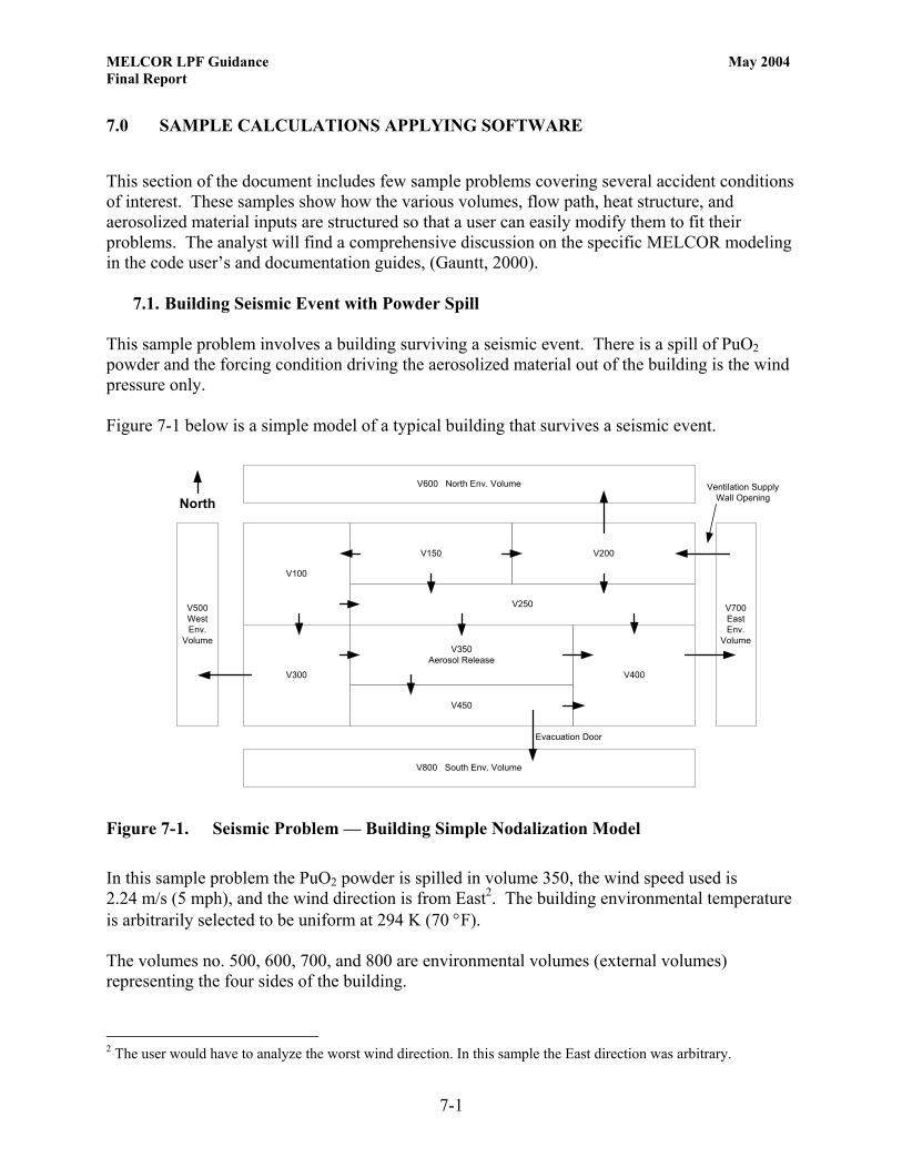
7.1. Building Seismic Event with Powder Spill This sample problem involves a building surviving a seismic event. There is a spill of PuO2 powder and the forcing condition driving the aerosolized material out of the building is the wind pressure only. Figure 7-1 below is a simple model of a typical building that survives a seismic event.
V100
V300
V150 V200
V250
V350Aerosol Release
V450
V400
V600 North Env. Volume
V800 South Env. Volume
V500WestEnv.
Volume
V700EastEnv.
Volume
Evacuation Door
Ventilation SupplyWall OpeningNorth
Figure 7-1. Seismic Problem — Building Simple Nodalization Model In this sample problem the PuO2 powder is spilled in volume 350, the wind speed used is 2.24 m/s (5 mph), and the wind direction is from East2. The building environmental temperature is arbitrarily selected to be uniform at 294 K (70 °F). The volumes no. 500, 600, 700, and 800 are environmental volumes (external volumes) representing the four sides of the building.
2 The user would have to analyze the worst wind direction. In this sample the East direction was arbitrary.

MELCOR LPF Guidance May 2004 Final Report
7-2
Table 7-1 gives the geometrical dimensions used for this simple model Table 7-1. Seismic Problem Building Dimensions
Building Dimensions Volume No.
Length
m Width
m Height
m Volume
m3 100 15.2 18.3 4.0 1104.4 150 25.9 16.5 4.0 1689.7 200 25.9 16.5 4.0 1689.7 250 51.8 1.8 4.0 375.5 300 13.7 15.2 4.0 828.3 350 30.5 10.7 4.0 1288.4 400 21.3 13.7 4.0 1159.6 450 30.5 3.0 4.0 368.1 500 N/A N/A N/A 1.00E+10 600 N/A N/A N/A 1.00E+10 700 N/A N/A N/A 1.00E+10 800 N/A N/A N/A 1.00E+10
The pressure inside the building is assumed to be atmospheric, 101352.9 Pa (14.7 psia). The equivalent wind pressure, applied to the environmental volumes No. 500, 600, 700, and 800, is given it Table 7-2. Table 7-2. Seismic Problem Environmental Volumes Pressure
Environmental Volumes Pressure Volume No.
Pressure
Ps Pressure
psia 500 101351.6992 (14.69982) 600 101351.8493 (14.69984) 700 101355.0013 (14.7) 800 101351.8493 (14.69984)
A flow diagram of the building depicted in Figure 7-1 above is given in Figure 7-2, where the full connectivity of all cells is outlined.

MELCOR LPF Guidance May 2004 Final Report
7-3
V100
V300
V150 V200
V350Aerosol Release V400
V450
V250
V500West
V600North
V800South
V700East
Figure 7-2. Seismic Problem — Building Simple Nodalization Flow Diagram
Note that the arrow directions in Figure 7-2 above represent a conventional positive direction of the flow. The MELCOR computer code will calculate the actual direction of the flow and will assign a new flow direction if the one assumed is not in the assigned conventional direction. Table 7-3 includes a description of all the flow paths connecting the volumes shown in Figures 7-1and 7-2 above, including the flow path areas used in the analysis.

MELCOR LPF Guidance May 2004 Final Report
7-4
Table 7-3. Seismic Problem Volume Connectivity
Volume Connectivity Junction No. (Flow Path)
From Volume
To Volume
Flow Area m2
Comments
110 100 300 0.0387 Single Pane Closed Door
115 100 250 0.0387 Single Pane Closed Door
120 150 100 0.0387 Single Pane Closed Door
125 300 350 0.0387 Single Pane Closed Door
130 150 250 0.0387 Single Pane Closed Door
135 150 200 0.0387 Single Pane Closed Door
140 200 250 0.0387 Single Pane Closed Door
145 250 350 0.0387 Single Pane Closed Door
150 250 400 0.0387 Single Pane Closed Door
155 350 400 0.0387 Single Pane Closed Door
160 350 450 0.0387 Single Pane Closed Door
165 450 400 0.0387 Single Pane Closed Door
170 300 500 0.0639 Double Pane Closed Door
175 200 600 0.0639 Double Pane Closed Door
180 400 700 0.0639 Double Pane Closed Door
185 450 800 Modulating Door (See Figure 7-3 Below)
Double Pane Closed Door
190 700 200 2.0 Ventilation Supply Wall Opening Due to Seismic Event
The modulating door (Junction No. 185) between volumes 450 and 8003 is modeled by using a simple variable flow area to simulate the door opening to allow building evacuation. Figure 7-3 shows the time-history of the junction flow area used in the simulation.
3 For simplicity this sample problem only opens one door. In actuality the user needs to model doors appropriately.

MELCOR LPF Guidance May 2004 Final Report
7-5
0
0.5
1
1.5
2
2.5
3
3.5
4
4.5
0 100 200 300 400 500 600 700 800 900 1000
Time [s]
Flow
Are
a [m
2 ]
Figure 7-3. Seismic Problem — Modulating Door Representation (Model of Room Area versus Time) The above shows how the door is initially closed with an associated flow area (Flow path area) equivalent to the area of the various gaps around the door. The full door flow area is used for a predetermined time until the door is re-closed and the area of the gaps is again in place. The amount of material released in volume No. 350 due to the seismic event is set for simplicity to 1.0 kg and the lognormal distribution used is all respirable as described in paragraph 4.3: Maximum aerosol particle diameter = 3 µm Minimum aerosol particle diameter = 0.01 µm (this is an arbitrary minimum) Volume-equivalent mass median particle diameter = 2.3 µm (8 µm AED) Geometric standard deviation of the particle size distribution = 2 (95%) The tabular function used to represent the initial aerosol release rate is shown in Figure 7-4 which is normalized to 1.0 kg of material released.

MELCOR LPF Guidance May 2004 Final Report
7-6
0.0
0.2
0.4
0.6
0.8
1.0
1.2
0 2 4 6 8 10 12 14 16 18
Time [s]
Mat
eria
l Rel
ease
d [k
g/s]
Figure 7-4. Seismic Problem Aerosol Material Release Rate in Volume No. 350
The definition of the heat structures is very simple as MELCOR input . The guidance given in the user’s guide is extensive (recommended reading). The input data file given for this sample problem can be easily adapted as a template for other analyses. When defining the environmental volumes only one heat structure is recommended (nominal heat structure of 0.001 m2) with a very small surface area. That is, when computing the amount of material released to the outside environment to evaluate the LPF, use of only one heat structure makes it easier to assess. The MELCOR computer code is executed and the results are given in graphical form. The conventional output of the code includes information useful to monitor the entire code run. For the purpose of assessing the Leak Path Factor, the following is a typical set of results using the PTFREAD MS Excel Add-in. Figure 7-5 shows the amount of aerosolized material (originally in volume 350) that has been transported out of the building into the environmental volumes 500, 600, 700, and 800.

MELCOR LPF Guidance May 2004 Final Report
7-7
0
0.01
0.02
0.03
0.04
0.05
0.06
0 2 4 6 8 10 12 14 16 18 20
Time [hr]
Mas
s [k
g]
Vol. 800
Vol. 500
Vol. 600 & Vol. 700
Figure 7-5. Seismic Problem Result — Aerosolized Material in Environmental Volumes
Figure 7-5 shows that the only environmental volumes containing aerosolized material are Vol. No. 500 and Vol. No. 800. The total amount of material transported out of the building is about 0.08 kg. The LPF can be expressed in percent of the material originally in volume 350. By manipulating the data used to generate Figure 7-5, the following Figure 7-6 represents the LPF of the building as percent of the material originally aerosolized in the building.

MELCOR LPF Guidance May 2004 Final Report
7-8
0
1
2
3
4
5
6
7
8
9
0 5 10 15 20
Time [hr]
LPF
[%]
Figure 7-6. Seismic Problem Result — Total Building LPF Additional data extracted from the MELCOR run is the amount of material deposited inside the building, Figure 7-7.
RN1-TMDTT
0
0.1
0.2
0.3
0.4
0.5
0.6
0.7
0.8
0.9
1
0 5 10 15 20Time [hr]
Mas
s [k
g]
Figure 7-7. Seismic Problem Result — Material Deposited Inside Building

MELCOR LPF Guidance May 2004 Final Report
7-9
Figures 7-5 and 7-7 show that the mass of aerosol is conserved and the total mass (outside and inside the building) is equal to 1.0 kg, the original mass of material in volume no. 350. In this particular sample problem the selected wind direction is from East. In general, the user should run MELCOR changing the direction of the wind to assess the most conservative results. Appendix C includes the input data file used to execute the above sample problem.
7.2. Building Seismic Event with Powder Spill and Exhaust Ventilation Operating This sample problem involves a building surviving a seismic event. There is a spill of PuO2 powder in volume No. 350 and the exhaust portion of the ventilation network is operating using a filtration system. This sample problem is basically the same as in paragraph 7.1 above. An additional environmental volume (Vol. 900) is added to simulate the filtration system, and fixed flows are imposed out of each building cell to the volume representing the filtration system. The assumed filter system efficiency is set to 0.005. Figure 7-8 is a simple model of the building, including the modification to accommodate the filtration system. In this model the ventilation supply is assumed to fail with the seismic event, leaving a wall opening in the East side of the building.
V100
V300
V150 V200
V250
V350Aerosol Release
V450
V400
V600North Env. Volume
V800 South Env. Volume
V500WestEnv.
Volume
V700EastEnv.
Volume
V900Filtration System
From V100, V150, V200, V250,V300, V350, V400, V450
Evacuation Door
Ventilation SupplyWall Opening
Figure 7-8. Building Nodalization for a Seismic Event with Exhaust Ventilation On

MELCOR LPF Guidance May 2004 Final Report
7-10
The assumed ventilation flows from each building cell to the system exhaust (Vol. No. 99) are listed in Table 7-4. The total exhaust flow is assumed to be 9.44 m3/s (20,000 cfm), and the individual flows out to the exhaust are taken as proportional to the cell geometrical volume. An additional MELCOR run is also made using a total exhaust flow of 14.16 m3/s (30,000 cfm). This latter flow data is shown in Table 7-5. Table 7-4. Seismic Problem Ventilation Flows (9.44 m3/s)
Ventilation Flows - (9.44 m3/s) From
Volume To
VolumeFlow m3/s
100 900 1.226 150 900 1.876 200 900 1.876 250 900 0.417 300 900 0.919 350 900 1.430 400 900 1.287 450 900 0.409
Table 7-5. Seismic Problem Ventilation Flows (14.16 m3/s)
Ventilation Flows - (14.16 m3/s) From
Volume To
VolumeFlow m3/s
100 900 1.839 150 900 2.813 200 900 2.813 250 900 0.625 300 900 1.379 350 900 2.145 400 900 1.931 450 900 0.613
It is noted that when using fixed flows in MELCOR, as in this example, the actual input required by the code is a flow velocity. This is accomplished using the time-dependent flow path and a tabular function describing the fluid velocity. In this particular case a 1.0 m2 reference flow area was used to yield the volumetric flow rate desired. The model flow diagram given in the previous sample problem is modified to accommodate the changes made to the model for ventilation. The modified model flow diagram is shown in Figure 7-9.

MELCOR LPF Guidance May 2004 Final Report
7-11
V100
V300
V150 V200
V350 V400
V450
V250
V500West
V600North
V800South
V700East
V900Filtration Volume
Figure 7-9. Seismic Problem (Ventilation On) —Building Nodalization Flow Diagram
Figure 7-10 shows the amount of aerosolized material (originally in volume 350) that has been transported out of the building into the environmental volumes. An analysis of the output shows that only volume No. 900 (the filtration system) receives aerosol.

MELCOR LPF Guidance May 2004 Final Report
7-12
0
0.1
0.2
0.3
0.4
0.5
0.6
0.7
0.8
0.9
0 0.5 1 1.5 2 2.5 3
Time [hr]
Mas
s [k
g]
Vol. 900
Figure 7-10. Seismic Problem Result (Ventilation On) —Aerosol Material in Volume Number 900 Figure 7-11 shows the amount of aerosol material deposited in the building.
0
0.05
0.1
0.15
0.2
0.25
0 0.5 1 1.5 2 2.5 3
Time [hr]
Mas
s [k
g]
Figure 7-11. Seismic Problem Result (Ventilation On) —Aerosol Material Deposited Inside Building

MELCOR LPF Guidance May 2004 Final Report
7-13
The building LPF can be computed using Figure7-11 above multiplied by the filtration efficiency and expressing the results in percent of the material originally in volume No. 350. Figure 7-12 shows the building LPF with a total ventilation flow of 9.44 m3/s.
0.00
0.05
0.10
0.15
0.20
0.25
0.30
0.35
0.40
0.45
0.0 0.5 1.0 1.5 2.0 2.5 3.0
Time [hr]
LPF
[%]
Figure 7-12. Seismic Problem Result (Ventilation On) —Building LPF (Total ventilation flow of 9.44 m3/s) Figure 7-13 shows the building LPF with a total ventilation flow of 14.16 m3/s.

MELCOR LPF Guidance May 2004 Final Report
7-14
0.00
0.05
0.10
0.15
0.20
0.25
0.30
0.35
0.40
0.45
0.0 0.5 1.0 1.5 2.0 2.5 3.0
Time [hr]
LPF
[%]
Figure 7-13. Seismic Problem Result (Ventilation On) —Building LPF (Total ventilation flow of 14.16 m3/s)
Appendix D includes the input data file used to execute this sample problem using a total ventilation flow of 9.44 m3/s.
7.3. Building Seismic Event with Powder Spill and Post Seismic Fire This sample problem is equal to the sample problem given in paragraph 7.1 with the addition of a fire in volume No. 360 (same volume where initially there is aerosolized material). Figure 7-14 is a simple model of the building as previously shown in paragraph 7.1.

MELCOR LPF Guidance May 2004 Final Report
7-15
V100
V300
V150 V200
V250
V350Aerosol Release
1 MW Fire
V450
V400
V600 North Env. Volume
V800 South Env. Volume
V500WestEnv.
Volume
V700EastEnv.
Volume
Evacuation Door
Ventilation SupplyWall Opening
Figure 7-14. Fire Problem — Nodalization of Building with a Fire in Volume No. 350
The flow diagram for this model is identical to the diagram shown in Figure 7-2. The fire input into this model is described in Table 7-6 and Figure 7-15. Table 7-6. Fire Mass Enthalpy and Energy
Fire Input Time Mass Enthalpy Energy
s kg/s J/kg W 0.0 0.0 0.0 0.0
300.0 0.001 1.0E+9 1.0E+6 900.0 0.001 1.0E+9 1.0E+6 1200.0 0.0 0.0 0.0 5000.0 0.0 0.0 0.0
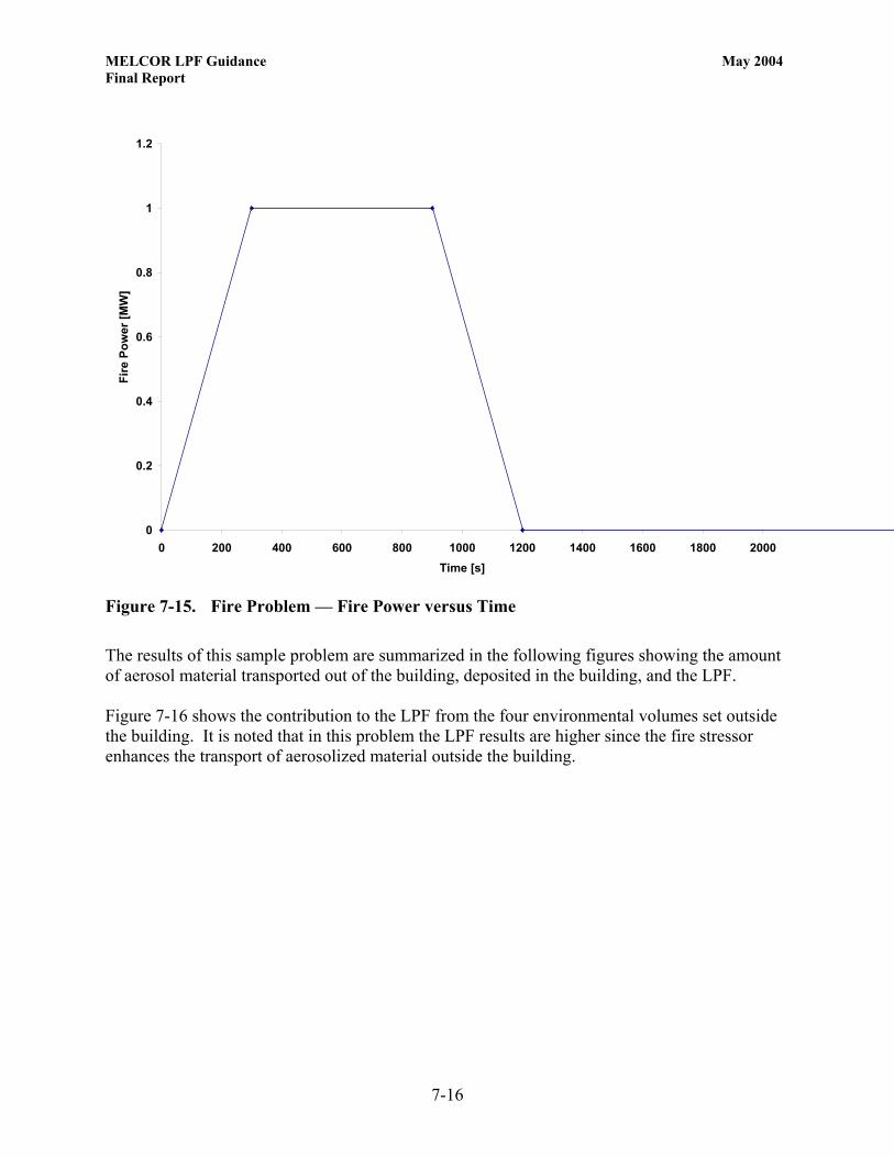
MELCOR LPF Guidance May 2004 Final Report
7-16
0
0.2
0.4
0.6
0.8
1
1.2
0 200 400 600 800 1000 1200 1400 1600 1800 2000Time [s]
Fire
Pow
er [M
W]
Figure 7-15. Fire Problem — Fire Power versus Time
The results of this sample problem are summarized in the following figures showing the amount of aerosol material transported out of the building, deposited in the building, and the LPF. Figure 7-16 shows the contribution to the LPF from the four environmental volumes set outside the building. It is noted that in this problem the LPF results are higher since the fire stressor enhances the transport of aerosolized material outside the building.

MELCOR LPF Guidance May 2004 Final Report
7-17
0.00
0.02
0.04
0.06
0.08
0.10
0.12
0.14
0.16
0.18
0 2 4 6 8 10Time [hr]
Mas
s [k
g]Vol. 800
Vol. 500
Vol. 700 Vol. 600
Figure 7-16. Fire Problem Result — Aerosolized Material in Environmental Volumes
0
0.1
0.2
0.3
0.4
0.5
0.6
0.7
0.8
0 2 4 6 8 10Time [hr]
Mas
s [k
g]
Figure 7-17. Fire Problem Result — Aerosol Material Deposited Inside Building

MELCOR LPF Guidance May 2004 Final Report
7-18
0
5
10
15
20
25
30
0 2 4 6 8 10
Time [hr]
LPF
[%]
Figure 7-18. Fire Problem Result — Total Building LPF
Appendix E includes the input data file used to execute this sample problem.
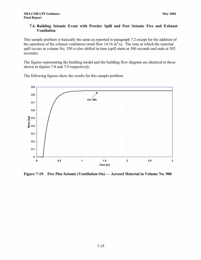
MELCOR LPF Guidance May 2004 Final Report
7-19
7.4. Building Seismic Event with Powder Spill and Post Seismic Fire and Exhaust Ventilation
This sample problem is basically the same as reported in paragraph 7.2 except for the addition of the operation of the exhaust ventilation (total flow 14.16 m3/s). The time at which the material spill occurs in volume No. 350 is also shifted in time (spill starts at 500 seconds and ends at 502 seconds). The figures representing the building model and the building flow diagram are identical to those shown in figures 7-8 and 7-9 respectively. The following figures show the results for this sample problem.
0
0.1
0.2
0.3
0.4
0.5
0.6
0.7
0.8
0.9
0 0.5 1 1.5 2 2.5 3Time [hr]
Mas
s [k
g]
Vol. 900
Figure 7-19. Fire Plus Seismic (Ventilation On) — Aerosol Material in Volume No. 900
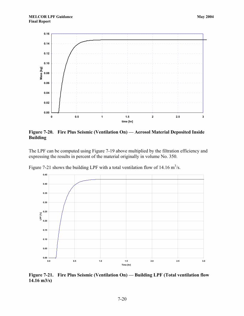
MELCOR LPF Guidance May 2004 Final Report
7-20
0.00
0.02
0.04
0.06
0.08
0.10
0.12
0.14
0.16
0 0.5 1 1.5 2 2.5 3time [hr]
Mas
s [k
g]
Figure 7-20. Fire Plus Seismic (Ventilation On) — Aerosol Material Deposited Inside Building The LPF can be computed using Figure 7-19 above multiplied by the filtration efficiency and expressing the results in percent of the material originally in volume No. 350. Figure 7-21 shows the building LPF with a total ventilation flow of 14.16 m3/s.
0.00
0.05
0.10
0.15
0.20
0.25
0.30
0.35
0.40
0.45
0.0 0.5 1.0 1.5 2.0 2.5 3.0
Time [hr]
LPF
[%]
Figure 7-21. Fire Plus Seismic (Ventilation On) — Building LPF (Total ventilation flow 14.16 m3/s)
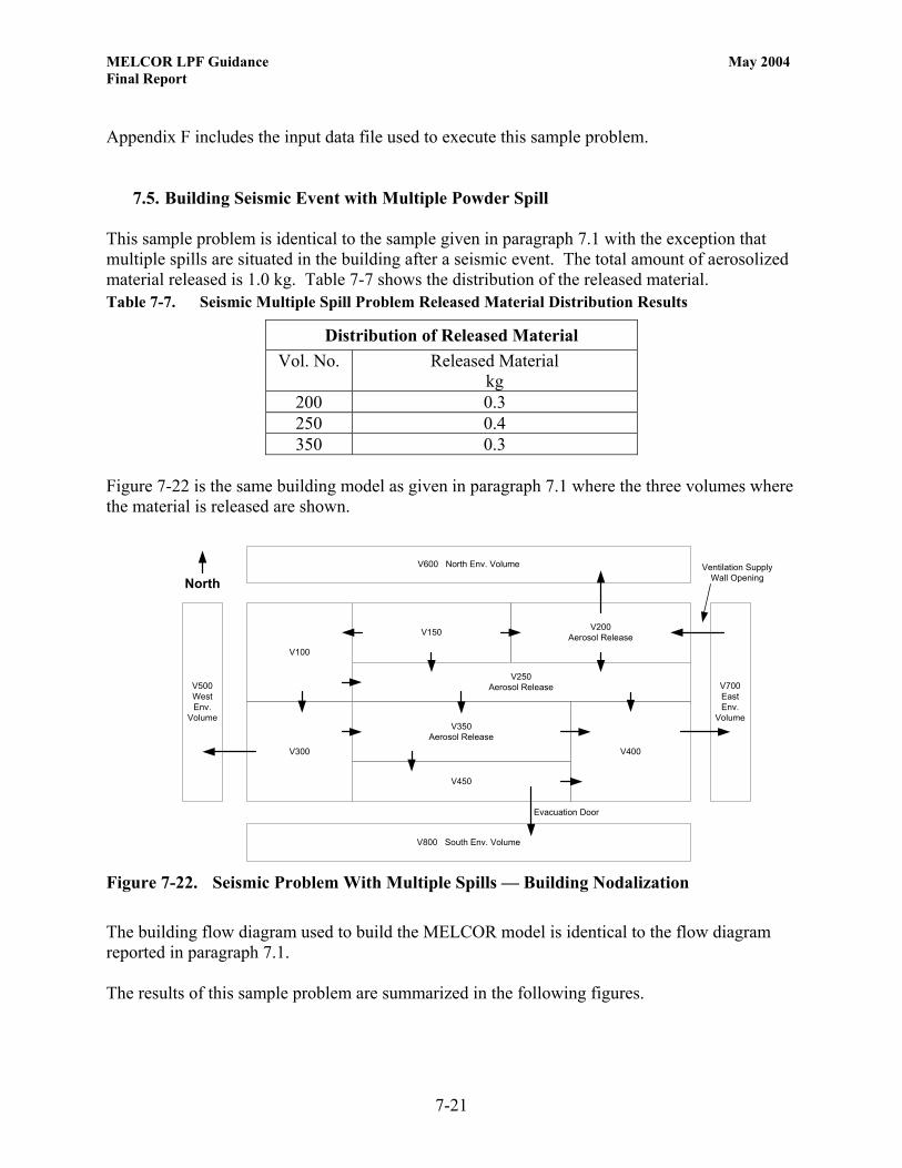
MELCOR LPF Guidance May 2004 Final Report
7-21
Appendix F includes the input data file used to execute this sample problem.
7.5. Building Seismic Event with Multiple Powder Spill This sample problem is identical to the sample given in paragraph 7.1 with the exception that multiple spills are situated in the building after a seismic event. The total amount of aerosolized material released is 1.0 kg. Table 7-7 shows the distribution of the released material. Table 7-7. Seismic Multiple Spill Problem Released Material Distribution Results
Distribution of Released Material Vol. No. Released Material
kg 200 0.3 250 0.4 350 0.3
Figure 7-22 is the same building model as given in paragraph 7.1 where the three volumes where the material is released are shown.
V100
V300
V150 V200Aerosol Release
V250Aerosol Release
V350Aerosol Release
V450
V400
V600 North Env. Volume
V800 South Env. Volume
V500WestEnv.
Volume
V700EastEnv.
Volume
Evacuation Door
Ventilation SupplyWall OpeningNorth
Figure 7-22. Seismic Problem With Multiple Spills — Building Nodalization
The building flow diagram used to build the MELCOR model is identical to the flow diagram reported in paragraph 7.1. The results of this sample problem are summarized in the following figures.

MELCOR LPF Guidance May 2004 Final Report
7-22
0
0.01
0.02
0.03
0.04
0.05
0.06
0.07
0 2 4 6 8 10 12 14 16 18 20Time [hr]
Mas
s [k
g]
Vol. 600
Vol. 800
Vol. 700Vol. 500
Figure 7-23. Seismic Problem With Multiple Spills — Aerosolized Material in Environmental Volumes
0.0
0.1
0.2
0.3
0.4
0.5
0.6
0.7
0.8
0.9
1.0
0 2 4 6 8 10 12 14 16 18 20Time [hr]
Mas
s [k
g]
Figure 7-24. Seismic Problem With Multiple Spills — Material Deposited Inside Building
The building LPF is evaluated by summing the material contribution as shown in Figure 7-23 above and expressing the results in percent of the total material originally in volumes 200, 250, and 350.

MELCOR LPF Guidance May 2004 Final Report
7-23
Figure 7-25 represents the building LPF as a percent of the material originally aerosolized inside the building.
0
2
4
6
8
10
12
14
0 5 10 15 20
Time [hr]
LPF
[%]
Figure 7-25. Seismic Problem With Multiple Spills — Building LPF A parametric study is performed to assess the influence of the amount of aerosolized material on the LPF. The original inventory of aerosolized material of 1.0 kg is reduced a few orders of magnitude. Table 7-8 shows the amount and distribution of released material used in the parametric study. Table 7-8. Parametric Study Distribution of Released Material Used
Distribution of Released Material Used in Parametric Study
Vol. No. Released Material
kg
Released Material
kg
ReleasedMaterial
kg
Released Material
kg 200 0.3 0.03 0.003 0.0003 250 0.4 0.04 0.004 0.0004 350 0.3 0.03 0.003 0.0003
Total 1.0 0.1 0.01 0.001 The resulting building LPF as a function of the Aerosolized released material is shown in the following Figure 7-26.

MELCOR LPF Guidance May 2004 Final Report
7-24
11.5
11.6
11.7
11.8
11.9
12.0
12.1
12.2
0.001 0.01 0.1 1
Total Aerosol Material Spilled [kg]
LPF
[%]
Figure 7-26. Influence of Released Material on LPF
Appendix G includes the input data file for this sample problem using a 1.0 kg total mass of released material.

MELCOR LPF Guidance May 2004 Final Report
8-1
8.0 ACRONYMS AND DEFINITIONS
Selected Terms and Definitions Used in Accident and Consequence Analysis & Software Quality Assurance Gap Analysis — Evaluation of the Software Quality Assurance attributes of specific computer
software against identified criteria. Leak Path Factor (LPF) – Defined as the fraction of airborne radioactive material released, due
to a forcing condition, as respirable particulate within the building that escapes via available pathways to the outside environment.
Aerodynamic Equivalent Diameter (AED) – Diameter of a sphere of density 1 g/cm that
exhibits the same terminal velocity as the particle subject of the analysis. Software — Computer programs, operating systems, procedures, and possibly associated
documentation and data pertaining to the operation of a computer system. [IEEE Standard 610.12-1990, IEEE Standard Glossary of Software Engineering Terminology]
Toolbox Codes — A small number of standard computer models (codes) supporting DOE safety
analysis, having widespread use, and meeting minimum qualification standards. These codes shall be sufficiently verified and validated, and as such, applicable to support 10 CFR 830 DSAs. That is to say, the analysts using these codes do not need to present additional defense as to their qualification, provided that they are sufficiently qualified to use the codes and the input parameters are valid.

MELCOR LPF Guidance May 2004 Final Report
8-2
INTENTIONALLY BLANK

MELCOR LPF Guidance May 2004 Final Report
9-1
9.0 REFERENCES
ASHRAE, 1977, Handbook of Fundamentals, American Society of Heating, Refrigerating and Air-Conditioning Engineers, Inc, 1997.
CRC, 1986, Handbook of Chemistry and Physics, 67th Edition, CRC Press, 1986. DOE 1994, U.S. Department of Energy, Airborne Release Fractions/Rates and Respirable
Fractions for Nonreactor Nuclear Facilities, DOE-HDBK-3010-94, December 12, 1994. DOE, 2002, U.S. Department of Energy, Preparation Guide for U.S. Department of Energy
Nonreactor Nuclear Facility Safety Reports, DOE-HDBK-3010-94, Change Notice 2, April 2002.
DOE, 2003, U. S. Department of Energy, MACCS2 Computer Code Application Guidance for
Documented Safety Analysis, September 2003. DOE, 2004, U.S. Department of Energy, Software Quality Assurance Improvement Plan:
MELCOR Gap Analysis, Final. Gauntt, 2000, Gauntt et al., MELCOR Computer Code Manuals, Version 1.8.5, NUREG/CR-
6119 Rev. 2, SAND2000-2417/1, May 2000. Mishima, 1973, J. Mishima, L. C. Schwendiman, Fractional Airborne Release of Uranium
(Representing Plutonium) During Burning of Contaminated Waste, BNWL-1730, Battelle Pacific Northwest Laboratory, Richland, WA, April 1973.
Murata, 1977, K. Murata, et al., Code Manual for CONTAIN 2.0: A Computer Code for Nuclear
Reactor Containment Analysis, NUREG/CR-6533, SAND 97-1735, December 1997. Polizzi, 2000, M. Polizzi, N. Flouras, Leak Path Factor Study at Savannah Rive Site, Safety
Analysis Working Group (SAWG) Workshop 2000, Santa Fe, NM. Polizzi, 2002, L. M. Polizzi, K. R. O’Kula, D. C. Thoman, Leak Path Factor Analysis for a
Large, Multiple-Cell Nuclear Facility, Safety Analysis Working Group (SAWG) Workshop 2002, Oak Ridge, TN.
SNL, 1983, Transuranic Package Transporter, TRUPACT-1, SARP, SAND 83-7077 (TTC-
0338) Sandia National Laboratory, GA Technologies, San Diego, CA, November 1983. Sutter, 1981, S. L. Sutter, J. W. Johnson, J. Mishima,, Aerosols Generated by Free Fall Spill of
Powders and Solutions in Static Air, NUREG/CR-2139, Battelle Pacific Northwest Laboratory, Richland, WA, December 1981.

MELCOR LPF Guidance May 2004 Final Report
9-2
Sutter, 1983, S. L. Sutter, Aerosols Generated by Releases of Pressurized Powders and Solutions in Static Air, NUREG/CR-3093, Battelle Pacific Northwest Laboratory, Richland, WA, August 1983.

MELCOR LPF Guidance May 2004 Final Report
9-3
APPENDICES Appendix Subject
A Steps to Run MELCOR
B Benchmark Problems
C Seismic Problem Input File
D Seismic Problem (Ventilation Operating) Input File
E Fire Problem Input File
F Fire Plus Seismic (Ventilation Operating) Input File
G Seismic Problem with Multiple Spills (Ventilation Operating) Input File

MELCOR LPF Guidance May 2004 Final Report
A-1
Appendix A. Steps to Run MELCOR The user needs to follow a few simple steps to run MELCOR on a Personal Computer. The MELCOR package includes two executables: MELGEN and MELCOR. 1. Prepare an input data file with a text editor. The file name can be any, e.g., input.txt or
sample1.inp, etc. 2. Open a Command Prompt Window in the folder where the input data file is located (this
assumes the user has set environmental variables in Windows to have the MELGEN/MELCOR folder in the path.
3. Execute MELGEN input data file (MELGEN input.txt) 4. Execute MELCOR input data file (MELCOR input.txt) 5. Use the MS Excel Add-in to analyze the output file (.PTF) or use Xymel software

MELCOR LPF Guidance May 2004 Final Report
- B-1 -
Appendix B. Benchmark Problems Several benchmarks were performed to assess the LPF evaluation using MELCOR and CONTAIN. The problems of interest are: Seismic spill – no ventilation (wind-driven LPF) Seismic spill – with ventilation Spill with large fire and ventilation Spill with small fire – no ventilation The building layout used is shown in Figure B-1 and the MELCOR model block diagram is shown in Figure B-2
NorthVol. 150
Vol. 200
Vol. 350
Vol. 400
Vol. 300
Vol. 250
Vol. 500
Vol. 450
South Side of BuildingMELCOR Volume 550
South EnvironmentMELCOR Volume 800
Ventilation SupplyMELCOR Volume 900
North EnvironmentMELCOR Volume 600
Filter VolumeMELCOR Volume 700
Figure B-1. Building Layout Used in Benchmark

MELCOR LPF Guidance May 2004 Final Report
- B-2 -
Vol. 150
Vol. 200
Vol. 350
Vol. 400
Vol. 500
Vol. 450
Vol. 250
Vol. 300
Vol. 600North Environmental Volume
Vol. 700Filter System
Vol. 900Ventilation Supply
Vol. 550South Side of Building
Vol. 800South Environmental Volume.
NORTH
Figure B-2. MELCOR Model Block Diagram
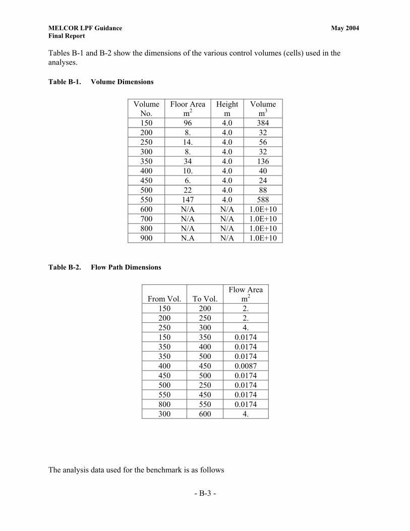
MELCOR LPF Guidance May 2004 Final Report
- B-3 -
Tables B-1 and B-2 show the dimensions of the various control volumes (cells) used in the analyses. Table B-1. Volume Dimensions
Volume
No. Floor Area
m2 Height
m Volume
m3 150 96 4.0 384 200 8. 4.0 32 250 14. 4.0 56 300 8. 4.0 32 350 34 4.0 136 400 10. 4.0 40 450 6. 4.0 24 500 22 4.0 88 550 147 4.0 588 600 N/A N/A 1.0E+10 700 N/A N/A 1.0E+10 800 N/A N/A 1.0E+10 900 N.A N/A 1.0E+10
Table B-2. Flow Path Dimensions
The analysis data used for the benchmark is as follows
From Vol. To Vol. Flow Area
m2 150 200 2. 200 250 2. 250 300 4. 150 350 0.0174 350 400 0.0174 350 500 0.0174 400 450 0.0087 450 500 0.0174 500 250 0.0174 550 450 0.0174 800 550 0.0174 300 600 4.

MELCOR LPF Guidance May 2004 Final Report
- B-4 -
Wind Speed 2.23 m/s (5 mph) Wind from South 1 g of PuO2 spilled in Vol. 150 in 2.0 s (Fully aerosolized and all respirable) Lognormal distribution of aerosolized material Maximum aerosol particle diameter, 3 µm Minimum aerosol particle diameter, 0.003 µm Volume-equivalent mass median particle diameter, 2.3 µm Geometric standard deviation of the particle size distribution, 2 Fire in Vol. 150 Ventilation flow from volume 150 to filters 0.93 m3/s Ventilation flow from volume 350 to filters 0.21 m3/s Vol. 150 Ventilation supply 0.71 m3/s Vol. 350 Ventilation supply 0.14 m3/s Filters efficiency 0.995 No cracks in the building structure The large fire profile used in the analysis is shown in Figure B-3
0
0.2
0.4
0.6
0.8
1
1.2
0 500 1000 1500 2000 2500
Time (s)
Fire
Pow
er (M
W)
Figure B-3. Large Fire Profile

MELCOR LPF Guidance May 2004 Final Report
- B-5 -
The small fire profile used in the analysis is shown in Figure B-4
0
0.1
0.2
0.3
0.4
0.5
0.6
0 500 1000 1500 2000 2500
Time (s)
Fire
Pow
er (M
W)
Figure B-4. Small Fire Profile

MELCOR LPF Guidance May 2004 Final Report
- B-6 -
Benchmark Results
Seismic Spill – No ventilation
0
1
2
3
4
5
6
7
8
0 5000 10000 15000 20000 25000 30000 35000 40000 45000 50000
Time (s)
LPF
(%)
MELCOR CONTAIN Figure B-5. Total LPF (Seismic Spill – No ventilation)

MELCOR LPF Guidance May 2004 Final Report
- B-7 -
Seismic Spill – With ventilation
0
0.1
0.2
0.3
0.4
0.5
0 500 1000 1500 2000 2500 3000 3500 4000 4500
Time (s)
LPF
(%)
MELCOR CONTAIN
Figure B-6. Total LPF (Seismic Spill – With ventilation)
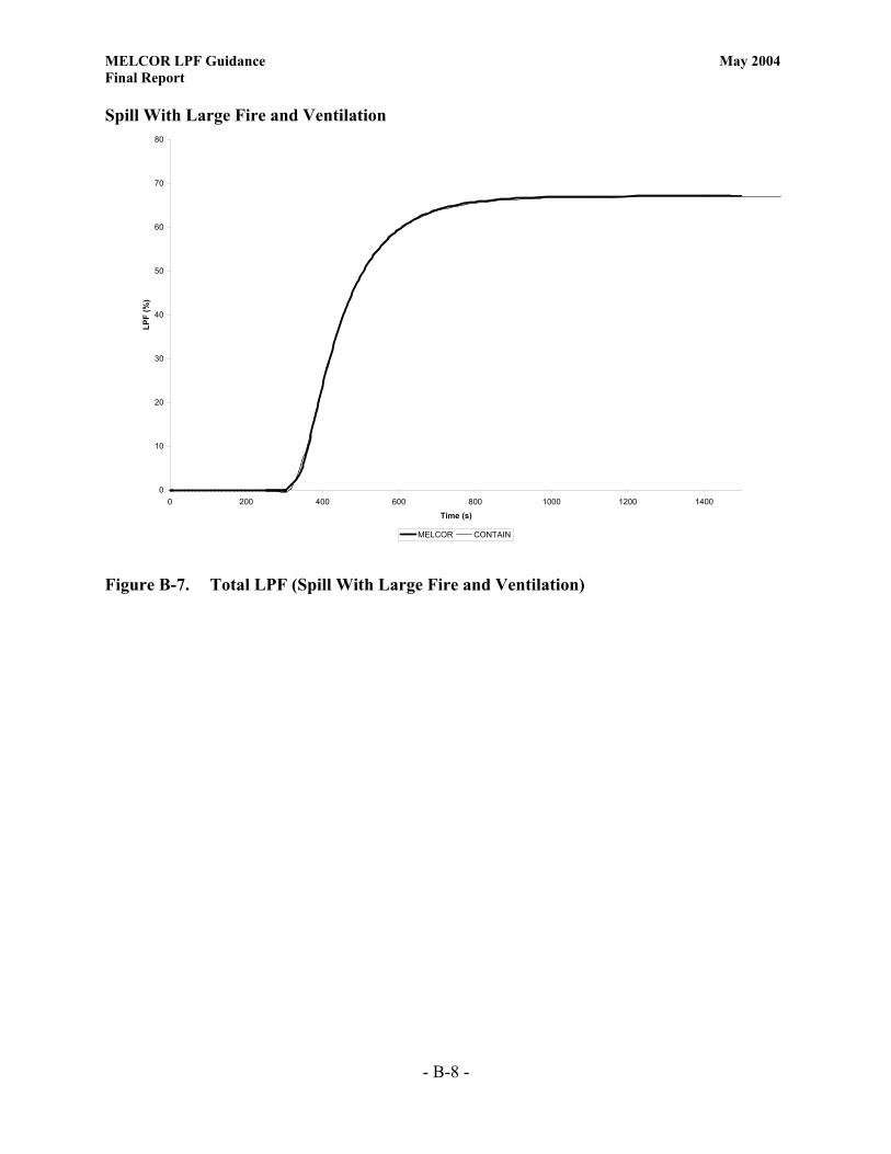
MELCOR LPF Guidance May 2004 Final Report
- B-8 -
Spill With Large Fire and Ventilation
0
10
20
30
40
50
60
70
80
0 200 400 600 800 1000 1200 1400
Time (s)
LPF
(%)
MELCOR CONTAIN
Figure B-7. Total LPF (Spill With Large Fire and Ventilation)

MELCOR LPF Guidance May 2004 Final Report
- B-9 -
Spill With Large Fire and Ventilation – Predicted Temperature in Volume 150
0
200
400
600
800
1000
1200
1400
0 500 1000 1500 2000 2500 3000 3500Time (s)
Tem
pera
ture
in V
olum
e 15
0 (K
)
MELCOR CONTAIN
Figure B-8. Temperature in Volume 150 (Spill With Large Fire and Ventilation)
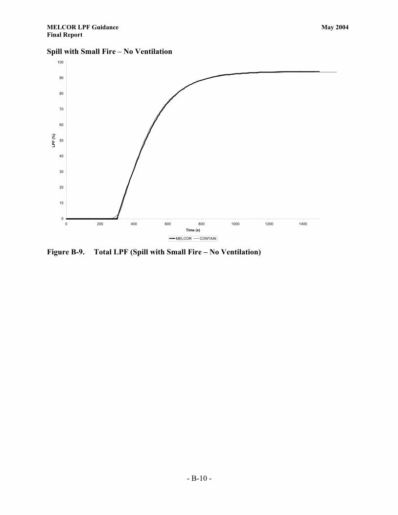
MELCOR LPF Guidance May 2004 Final Report
- B-10 -
Spill with Small Fire – No Ventilation
0
10
20
30
40
50
60
70
80
90
100
0 200 400 600 800 1000 1200 1400
Time (s)
LPF
(%)
MELCOR CONTAIN Figure B-9. Total LPF (Spill with Small Fire – No Ventilation)

MELCOR LPF Guidance May 2004 Final Report
- B-11 -
Spill with Small Fire – No Ventilation - Predicted Temperature in Volume 150
0
100
200
300
400
500
600
700
800
0 500 1000 1500 2000 2500 3000
Time (s)
Tem
pera
ture
in V
olum
e 15
0 (K
)
MELCOR CONTAIN Figure B-10. Temperature in Volume 150 (Spill with Small Fire – No Ventilation)

MELCOR LPF Guidance May 2004 Final Report
- C-1 -
Appendix C. Seismic Problem Input File *EOR* MELGEN * ********************************** ********** MELGEN INPUT ********** ********************************** * THE FOLLOWING CARD IS A TITLE CARD TO IDENTIFY THE INPUT * DATA FILE AND OUTPUT RUN TITLE 'TEST PROBLEM' * DTTIME 0.0001 * INITIAL TIME-STEP OF 1 MS * CRTOUT * 80-COLUMN OUTPUT FORMAT * ********* * FILES * ********* * DEFINITION OF OUTPUT FILE NAMES * THE USER CAN ASSIGN FILE NAMES AT HIS/HER DISCRETION OUTPUTFILE SAMPLEG.OUT DIAGFILE SAMPLEG.DIA RESTARTFILE SAMPLE.RST * * * DEFINITION OF DEFAULT FLUID * AIR DEFINITION – IN THIS PROBLEM THE DEFAULT FLUID IS * DEFINED AS AIR 80% N2 AND 20% O2 NCG001 N2 4 * N2 IS MATERIAL NO. 4 NCG002 O2 5 * O2 IS MATERIAL NO. 5 * END AIR DEFINITION ************************** * PRIMARY SYSTEM VOLUMES * ************************** * FOR A TYPICAL LPF ANALYSIS THERE IS NO LIMITATION ON THE * NUMBER OF CONTROL VOLUMES THE USER CAN SET IN THE ANALYSIS * * SEE THE CVHUSERGUIDE DOCUMENT FOR THE FOLLOWING INPUT DATA CARD CV10000 ROOM100 2 1 1 * ROOM-100 * VOLUME ENV. CONDITIONS CV100A1 PVOL 101352.9 * INITIAL PRESSURE IN PA * NEXT INPUT CARD REPRESENTS THE CONTROL VOLUME INITIAL * CONDITIONS CV100A4 MLFR.4 .8 MLFR.5 .2 TATM 294.3 RHUM 0.0 * 80% N2, 20% O2 * ALTITUDE OF CELL AND VOLUME * SEE THE CVHUSERGUIDE DOCUMENT FOR THE FOLLOWING INPUT DATA CARDS CV100B1 0.0 0.0 * BOTTOM 0.0 CV100B2 4. 1104.4 * TOTAL VOLUME * * THIS IS THE NEXT VOLUME (CELL) – COMMENTS AS ABOVE CV15000 ROOM150 2 1 1 * ROOM-150 * VOLUME ENV. CONDITIONS CV150A1 PVOL 101352.9 * INITIAL PRESSURE CV150A4 MLFR.4 .8 MLFR.5 .2 TATM 294.3 RHUM 0.0 * 80% N2, 20% O2 * ALTITUDE OF CELL AND VOLUME CV150B1 0.0 0.0 * BOTTOM AT 0.0 CV150B2 4. 1689.7 * TOTAL VOLUME * * CV20000 ROOM200 2 1 1 * ROOM-200 CV200A1 PVOL 101352.9 * INITIAL PRESSURE CV200A4 MLFR.4 .8 MLFR.5 .2 TATM 294.3 RHUM 0.0 * 80% N2, 20% O2 * ALTITUDE OF CELL AND VOLUME CV200B1 0.0 0.0 * BOTTOM AT 0.0 CV200B2 4.0 1689.7 * TOTAL VOLUME * * CV25000 ROOM250 2 1 1 * ROOM-250 CV250A1 PVOL 101352.9 * INITIAL PRESSURE

MELCOR LPF Guidance May 2004 Final Report
- C-2 -
CV250A4 MLFR.4 .8 MLFR.5 .2 TATM 294.3 RHUM 0.0 * 80% N2, 20% O2 * ALTITUDE OF CELL AND VOLUME CV250B1 0.0 0.0 * BOTTOM AT 0.0 CV250B2 4.0 375.5 * TOTAL VOLUME * * CV30000 ROOM300 2 1 1 * ROOM-300 CV300A1 PVOL 101352.9 * INITIAL PRESSURE CV300A4 MLFR.4 .8 MLFR.5 .2 TATM 294.3 RHUM 0.0 * 80% N2, 20% O2 * ALTITUDE OF CELL AND VOLUME CV300B1 0.0 0.0 * BOTTOM AT 0.0 CV300B2 4.0 828.3 * TOTAL VOLUME * * CV35000 ROOM350 2 1 1 * ROOM-350 CV350A1 PVOL 101352.9 * INITIAL PRESSURE CV350A4 MLFR.4 .8 MLFR.5 .2 TATM 294.3 RHUM 0.0 * 80% N2, 20% O2 * ALTITUDE OF CELL AND VOLUME CV350B1 0.0 0.0 * BOTTOM AT 0.0 CV350B2 4.0 1288.4 * TOTAL VOLUME * * CV40000 ROOM400 2 1 1 * ROOM-400 CV400A1 PVOL 101352.9 * INITIAL PRESSURE CV400A4 MLFR.4 .8 MLFR.5 .2 TATM 294.3 RHUM 0.0 * 80% N2, 20% O2 * ALTITUDE OF CELL AND VOLUME CV400B1 0.0 0.0 * BOTTOM AT 0.0 CV400B2 4.0 1159.6 * TOTAL VOLUME * * CV45000 ROOM450 2 1 1 * ROOM-400 CV450A1 PVOL 101352.9 * INITIAL PRESSURE CV450A4 MLFR.4 .8 MLFR.5 .2 TATM 294.3 RHUM 0.0 * 80% N2, 20% O2 * ALTITUDE OF CELL AND VOLUME CV450B1 0.0 0.0 * BOTTOM AT 0.0 CV450B2 4.0 368.1 * TOTAL VOLUME * * **************************************** * ENVIRONMENTAL VOLUME - OUTSIDE CELLS * **************************************** * THE EXTERNAL/ENVIRONMENTAL VOLUMES ARE USED TO COLLECT THE LPF DATA CV50000 WEST-VOL500 2 1 1 * ENV-500 WEST CV500A1 PVOL 101351.6992 * INITIAL PRESSURE CV500A4 MLFR.4 .8 MLFR.5 .2 TATM 294.3 RHUM 0.0 * 80% N2, 20% O2 * ALTITUDE OF CELL AND VOLUME CV500B1 0.0 0.0 * BOTTOM AT 0.0 * FOR THE EXTERNAL/ENVIRONMENTAL VOLUMES A GEOMETRICAL VOLUME * OF 1.0E+10 M3 IS ADEQUATE CV500B2 4.0 1.0E10 * TOTAL VOLUME * * CV60000 NORTH-VOL600 2 1 1 * ENV-600 NORTH CV600A1 PVOL 101351.8493 * INITIAL PRESSURE CV600A4 MLFR.4 .8 MLFR.5 .2 TATM 294.3 RHUM 0.0 * 80% N2, 20% O2 * ALTITUDE OF CELL AND VOLUME CV600B1 0.0 0.0 * BOTTOM AT 0.0 CV600B2 4.0 1.0E10 * TOTAL VOLUME * * * WIND FROM EAST AT 5 MPH CV70000 EAST-VOL700 2 1 1 * ENV-700 EAST CV700A1 PVOL 101355.0013 * INITIAL PRESSURE CV700A4 MLFR.4 .8 MLFR.5 .2 TATM 294.3 RHUM 0.0 * 80% N2, 20% O2 * ALTITUDE OF CELL AND VOLUME CV700B1 0.0 0.0 * BOTTOM AT 0.0 CV700B2 4.0 1.0E10 * TOTAL VOLUME * * CV80000 SOUTH-VOL800 2 1 1 * ENV-800 SOUTH CV800A1 PVOL 101351.8493 * INITIAL PRESSURE

MELCOR LPF Guidance May 2004 Final Report
- C-3 -
CV800A4 MLFR.4 .8 MLFR.5 .2 TATM 294.3 RHUM 0.0 * 80% N2, 20% O2 * ALTITUDE OF CELL AND VOLUME CV800B1 0.0 0.0 * BOTTOM AT 0.0 CV800B2 4.0 1.0E10 * TOTAL VOLUME * * * *********************** * INTERNAL FLOW PATHS * *********************** * THE NEXT SET OF INPUT CARD ARE TYPICAL FLOW PATH (JUNCTION) DATA * SEE THE FLUSERGUIDE DOCUMENT FOR EXTENDED DETAILS * VOLUMES JUNCTION ELEVATION * FROM TO FROM TO FL11000 100-300 100 300 1. 1. FL11001 0.0387 0.05 1.0 * AREA, LENGTH, OPEN FRACTION * NEXT CARD INCLUDES THE FORWARD AND REVERSE LOSS COEFFICIENT FL11003 1.5 1.5 * LOSS COEFFICIENTS * NEXT CARD INCLUDES THE FLOW AREA, FLOW PATH LENGTH, AND FLOW PATH * HYDRAULIC DIAMETER FL110S0 0.0387 0.0508 0.0254 * A, L, HYD.DIAM. * * * VOLUMES JUNCT.ELEV. * FROM TO FROM TO FL11500 100-250 100 250 1. 1. FL11501 0.0387 0.05 1.0 * A, L, FRACTION OPEN FL11503 1.5 1.5 * LOSS COEFFICIENT FL115S0 0.0387 0.0508 0.0254 * A, L, HYD.DIAM. * * * VOLUMES JUNCT.ELEV. * FROM TO FROM TO FL12000 150-100 150 100 1. 1. FL12001 0.0387 0.05 1.0 * A, L, FRACTION OPEN FL12003 1.5 1.5 * LOSS COEFFICIENT FL120S0 0.0387 0.0508 0.0254 * A, L, HYD.DIAM. * * * VOLUMES JUNCT.ELEV. * FROM TO FROM TO FL12500 300-350 300 350 1. 1. FL12501 0.0387 0.05 1.0 * A, L, FRACTION OPEN FL12503 1.5 1.5 * LOSS COEFFICIENT FL125S0 0.0387 0.0508 0.0254 * A, L, HYD.DIAM. * * * VOLUMES JUNCT.ELEV. * FROM TO FROM TO FL13000 150-250 150 250 1. 1. FL13001 0.0387 0.05 1.0 * A, L, FRACTION OPEN FL13003 1.5 1.5 * LOSS COEFFICIENT FL130S0 0.0387 0.0508 0.0254 * A, L, HYD.DIAM. * * * VOLUMES JUNCT.ELEV. * FROM TO FROM TO FL13500 150-200 150 200 1. 1. FL13501 0.0387 0.05 1.0 * A, L, FRACTION OPEN FL13503 1.5 1.5 * LOSS COEFFICIENT FL135S0 0.0387 0.0508 0.0254 * A, L, HYD.DIAM. * * * VOLUMES JUNCT.ELEV. * FROM TO FROM TO FL14000 200-250 200 250 1. 1. FL14001 0.0387 0.05 1.0 * A, L, FRACTION OPEN FL14003 1.5 1.5 * LOSS COEFFICIENT FL140S0 0.0387 0.0508 0.0254 * A, L, HYD.DIAM. * *

MELCOR LPF Guidance May 2004 Final Report
- C-4 -
* VOLUMES JUNCT.ELEV. * FROM TO FROM TO FL14500 250-350 250 350 1. 1. FL14501 0.0387 0.05 1.0 * A, L, FRACTION OPEN FL14503 1.5 1.5 * LOSS COEFFICIENT FL145S0 0.0387 0.0508 0.0254 * A, L, HYD.DIAM. * * * VOLUMES JUNCT.ELEV. * FROM TO FROM TO FL15000 250-400 250 400 1. 1. FL15001 0.0387 0.05 1.0 * A, L, FRACTION OPEN FL15003 1.5 1.5 * LOSS COEFFICIENT FL150S0 0.0387 0.0508 0.0254 * A, L, HYD.DIAM. * * * VOLUMES JUNCT.ELEV. * FROM TO FROM TO FL15500 350-400 350 400 1. 1. FL15501 0.0387 0.05 1.0 * A, L, FRACTION OPEN FL15503 1.5 1.5 * LOSS COEFFICIENT FL155S0 0.0387 0.0508 0.0254 * A, L, HYD.DIAM. * * * VOLUMES JUNCT.ELEV. * FROM TO FROM TO FL16000 350-450 350 450 1. 1. FL16001 0.0387 0.05 1.0 * A, L, FRACTION OPEN FL16003 1.5 1.5 * LOSS COEFFICIENT FL160S0 0.0387 0.0508 0.0254 * A, L, HYD.DIAM. * * * VOLUMES JUNCT.ELEV. * FROM TO FROM TO FL16500 450-400 450 400 1. 1. FL16501 0.0387 0.05 1.0 * A, L, FRACTION OPEN FL16503 1.5 1.5 * LOSS COEFFICIENT FL165S0 0.0387 0.0508 0.0254 * A, L, HYD.DIAM. * * ********************************** * FLOW PATHS FROM/TO EXTERNAL VOLUMES * ********************************** * VOLUMES JUNCT.ELEV. * FROM TO FROM TO FL17000 300-500 300 500 1. 1. FL17001 0.0639 0.05 1.0 * A, L, FRACTION OPEN FL17003 1.5 1.5 * LOSS COEFFICIENT FL170S0 0.0639 0.0508 0.0254 * A, L, HYD.DIAM. * * * VOLUMES JUNCT.ELEV. * FROM TO FROM TO FL17500 200-600 200 600 1. 1. FL17501 0.0639 0.05 1.0 * A, L, FRACTION OPEN FL17503 1.5 1.5 * LOSS COEFFICIENT FL175S0 0.0639 0.0508 0.0254 * A, L, HYD.DIAM. * * * VOLUMES JUNCT.ELEV. * FROM TO FROM TO FL18000 400-700 400 700 1. 1. FL18001 0.0639 0.05 1.0 * A, L, FRACTION OPEN FL18003 1.5 1.5 * LOSS COEFFICIENT FL180S0 0.0639 0.0508 0.0254 * A, L, HYD.DIAM. * * * VOLUMES JUNCT.ELEV. * FROM TO FROM TO FL18500 450-800 450 800 1. 1. FL18501 3.9 0.05 1.0 * A, L, FRACTION OPEN

MELCOR LPF Guidance May 2004 Final Report
- C-5 -
FL18503 1.5 1.5 * LOSS COEFFICIENT FL185S0 3.9 0.0508 1.6 * A, L, HYD.DIAM. FL185V0 -1 251 251 * CONTROL FUNCTION TO USE TABULAR FUCTION 233 * SEE THE CFUSERGUIDE DOCUMENT FOR EXTENDED DETAILS CF25100 'JUN CONROL' TAB-FUN 1 1.0 * TRIP ON TIME CF25101 0.0 CF25103 233 * TAB FUNCTION NUMBER CF25110 1.0 0.0 TIME * TAB FUNCTION NEXT * SEE THE TFUSERGUIDE DOCUMENT FOR EXTENDED DETAILS TF23300 'MOD DOOR' 6 1.0 0. TF23310 0.0 0.0164 TF23311 120. 0.0164 TF23312 120. 1.0 TF23313 720. 1.0 TF23314 720. 0.0164 TF23315 200000. 0.0164 * * VENTILATION SUPPLY WALL OPENING * VOLUMES JUNCT.ELEV. * FROM TO FROM TO FL19000 700-200 700 200 1. 1. FL19001 2.0 0.05 1.0 * A, L, FRACTION OPEN FL19003 1.5 1.5 * LOSS COEFFICIENT FL190S0 2.0 0.3048 2.0 * A, L, HYD.DIAM. * * * * ************************* * HEAT STRUCTURES INPUT * ************************* * * SEE THE HSUSERGUIDE DOCUMENT FOR EXTENDED DETAILS * * HS10001000 3 1 * 3 NODES, RECTANGULAR GEOMETRY HS10001001 'FLOOR 100' * STRUCTURE NAME HS10001002 0.0 0.0 * BOTTOM AT 0.0 M, HORIZONTAL HS10001100 -1 1 0.0 * DEFINE NODE POSITIONS, FIRST AT 0.0 M HS10001101 0.3048 3 * THIRD NODE NODE AT 0.3048 M HS10001200 -1 * DEFINE MATERIAL HS10001201 'CONCRETE' 2 * 2 MESH POINTS HS10001300 0 * NO INTERNAL POWER SOURCE HS10001400 0 * ADIABATIC LOWER BC HS10001600 1 100 EXT 0.0 0.0 * UPPER BC * AREA CHAR.L WIDTH * EXTERNAL HEAT TRANSFER HS10001700 278.7 20.0 20.0 * SUFRACE AREA M**2 * HS10002000 3 1 HS10002001 'CEILING 100' HS10002002 4.0 0.0 * HEIGHT, HORIZONTAL HS10002100 -1 1 0.0 HS10002101 0.3048 3 HS10002200 -1 HS10002201 'CONCRETE' 2 HS10002300 0 HS10002400 1 100 EXT 0.0 0.0 * AREA CHAR.L WIDTH HS10002500 278.7 5.0 5.0 HS10002600 0 * HS10003000 3 1 HS10003001 'WALL 100' HS10003002 0.0 1.0 * BOTTOM AT 0.0 M, VERTICAL HS10003100 -1 1 0.0 HS10003101 0.3048 3 HS10003200 -1 HS10003201 'CONCRETE' 2 HS10003300 0

MELCOR LPF Guidance May 2004 Final Report
- C-6 -
HS10003400 1 100 EXT 0.0 0.0 * AREA CHAR.L WIDTH HS10003500 265.7 3.0 3.0 HS10003600 1 300 EXT 0.0 0.0 * AREA CHAR.L WIDTH HS10003700 265.7 3.0 3.0 * * * HS15001000 3 1 * 3 NODES, RECTANGULAR GEOMETRY HS15001001 'FLOOR 150' * STRUCTURE NAME HS15001002 0.0 0.0 * BOTTOM AT 0.0 M, HORIZONTAL HS15001100 -1 1 0.0 * DEFINE NODE POSITIONS, FIRST AT 0.0 M HS15001101 0.3048 3 * THIRD NODE NODE AT 0.3048 M HS15001200 -1 * DEFINE MATERIAL HS15001201 'CONCRETE' 2 * 2 MESH POINTS HS15001300 0 * NO INTERNAL POWER SOURCE HS15001400 0 * ADIABATIC LOWER BC HS15001600 1 150 EXT 0.0 0.0 * UPPER BC * AREA CHAR.L WIDTH * EXTERNAL HEAT TRANSFER HS15001700 426.4 20.0 20.0 * SUFRACE AREA M**2 * HS15002000 3 1 HS15002001 'CEILING 150' HS15002002 4.0 0.0 * BOTTOM NB HS15002100 -1 1 0.0 HS15002101 0.3048 3 HS15002200 -1 HS15002201 'CONCRETE' 2 HS15002300 0 HS15002400 1 150 EXT 0.0 0.0 * AREA CHAR.L WIDTH HS15002500 426.4 5.0 5.0 HS15002600 0 * HS15003000 3 1 HS15003001 'WALL 150' HS15003002 0.0 1.0 * BOTTOM AT 0.0 M, VERTICAL HS15003100 -1 1 0.0 HS15003101 0.3048 3 HS15003200 -1 HS15003201 'CONCRETE' 2 HS15003300 0 HS15003400 1 150 EXT 0.0 0.0 * AREA CHAR.L WIDTH HS15003500 335.8 3.0 3.0 HS15003600 1 300 EXT 0.0 0.0 * AREA CHAR.L WIDTH HS15003700 335.8 3.0 3.0 * * * HS20001000 3 1 * 3 NODES, RECTANGULAR GEOMETRY HS20001001 'FLOOR 200' * STRUCTURE NAME HS20001002 0.0 0.0 * BOTTOM AT 0.0 M, HORIZONTAL HS20001100 -1 1 0.0 * DEFINE NODE POSITIONS, FIRST AT 0.0 M HS20001101 0.3048 3 * THIRD NODE NODE AT 0.3048 M HS20001200 -1 * DEFINE MATERIAL HS20001201 'CONCRETE' 2 * 2 MESH POINTS HS20001300 0 * NO INTERNAL POWER SOURCE HS20001400 0 * ADIABATIC LOWER BC HS20001600 1 200 EXT 0.0 0.0 * UPPER BC * AREA CHAR.L WIDTH * EXTERNAL HEAT TRANSFER HS20001700 426.4 20.0 20.0 * SUFRACE AREA M**2 * HS20002000 3 1 HS20002001 'CEILING 200' HS20002002 4.0 0.0 * BOTTOM NB HS20002100 -1 1 0.0 HS20002101 0.3048 3 HS20002200 -1

MELCOR LPF Guidance May 2004 Final Report
- C-7 -
HS20002201 'CONCRETE' 2 HS20002300 0 HS20002400 1 200 EXT 0.0 0.0 * AREA CHAR.L WIDTH HS20002500 426.4 5.0 5.0 HS20002600 0 * HS20003000 3 1 HS20003001 'WALL 200' HS20003002 0.0 1.0 * BOTTOM AT 0.0 M, VERTICAL HS20003100 -1 1 0.0 HS20003101 0.3048 3 HS20003200 -1 HS20003201 'CONCRETE' 2 HS20003300 0 HS20003400 1 200 EXT 0.0 0.0 * AREA CHAR.L WIDTH HS20003500 335.8 3.0 3.0 HS20003600 1 300 EXT 0.0 0.0 * AREA CHAR.L WIDTH HS20003700 335.8 3.0 3.0 * * * HS25001000 3 1 * 3 NODES, RECTANGULAR GEOMETRY HS25001001 'FLOOR 250' * STRUCTURE NAME HS25001002 0.0 0.0 * BOTTOM AT 0.0 M, HORIZONTAL HS25001100 -1 1 0.0 * DEFINE NODE POSITIONS, FIRST AT 0.0 M HS25001101 0.3048 3 * THIRD NODE NODE AT 0.3048 M HS25001200 -1 * DEFINE MATERIAL HS25001201 'CONCRETE' 2 * 2 MESH POINTS HS25001300 0 * NO INTERNAL POWER SOURCE HS25001400 0 * ADIABATIC LOWER BC HS25001600 1 250 EXT 0.0 0.0 * UPPER BC * AREA CHAR.L WIDTH * EXTERNAL HEAT TRANSFER HS25001700 94.8 20.0 20.0 * SUFRACE AREA M**2 * HS25002000 3 1 HS25002001 'CEILING 250' HS25002002 4.0 0.0 * BOTTOM NB HS25002100 -1 1 0.0 HS25002101 0.3048 3 HS25002200 -1 HS25002201 'CONCRETE' 2 HS25002300 0 HS25002400 1 250 EXT 0.0 0.0 * AREA CHAR.L WIDTH HS25002500 94.8 5.0 5.0 HS25002600 0 * HS25003000 3 1 HS25003001 'WALL 250' HS25003002 0.0 1.0 * BOTTOM AT 0.0 M, VERTICAL HS25003100 -1 1 0.0 HS25003101 0.3048 3 HS25003200 -1 HS25003201 'CONCRETE' 2 HS25003300 0 HS25003400 1 250 EXT 0.0 0.0 * AREA CHAR.L WIDTH HS25003500 425.1 3.0 3.0 HS25003600 1 300 EXT 0.0 0.0 * AREA CHAR.L WIDTH HS25003700 425.1 3.0 3.0 * * * HS30001000 3 1 * 3 NODES, RECTANGULAR GEOMETRY HS30001001 'FLOOR 300' * STRUCTURE NAME HS30001002 0.0 0.0 * BOTTOM AT 0.0 M, HORIZONTAL HS30001100 -1 1 0.0 * DEFINE NODE POSITIONS, FIRST AT 0.0 M

MELCOR LPF Guidance May 2004 Final Report
- C-8 -
HS30001101 0.3048 3 * THIRD NODE NODE AT 0.3048 M HS30001200 -1 * DEFINE MATERIAL HS30001201 'CONCRETE' 2 * 2 MESH POINTS HS30001300 0 * NO INTERNAL POWER SOURCE HS30001400 0 * ADIABATIC LOWER BC HS30001600 1 300 EXT 0.0 0.0 * UPPER BC * AREA CHAR.L WIDTH * EXTERNAL HEAT TRANSFER HS30001700 209. 20.0 20.0 * SUFRACE AREA M**2 * HS30002000 3 1 HS30002001 'CEILING 300' HS30002002 4.0 0.0 * BOTTOM NB HS30002100 -1 1 0.0 HS30002101 0.3048 3 HS30002200 -1 HS30002201 'CONCRETE' 2 HS30002300 0 HS30002400 1 300 EXT 0.0 0.0 * AREA CHAR.L WIDTH HS30002500 209. 5.0 5.0 HS30002600 0 * HS30003000 3 1 HS30003001 'WALL 300' HS30003002 0.0 1.0 * BOTTOM AT 0.0 M, VERTICAL HS30003100 -1 1 0.0 HS30003101 0.3048 3 HS30003200 -1 HS30003201 'CONCRETE' 2 HS30003300 0 HS30003400 1 300 EXT 0.0 0.0 * AREA CHAR.L WIDTH HS30003500 229.5 3.0 3.0 HS30003600 1 150 EXT 0.0 0.0 * AREA CHAR.L WIDTH HS30003700 229.5 3.0 3.0 * * * HS35001000 3 1 * 3 NODES, RECTANGULAR GEOMETRY HS35001001 'FLOOR 350' * STRUCTURE NAME HS35001002 0.0 0.0 * BOTTOM AT 0.0 M, HORIZONTAL HS35001100 -1 1 0.0 * DEFINE NODE POSITIONS, FIRST AT 0.0 M HS35001101 0.3048 3 * THIRD NODE NODE AT 0.3048 M HS35001200 -1 * DEFINE MATERIAL HS35001201 'CONCRETE' 2 * 2 MESH POINTS HS35001300 0 * NO INTERNAL POWER SOURCE HS35001400 0 * ADIABATIC LOWER BC HS35001600 1 350 EXT 0.0 0.0 * UPPER BC * AREA CHAR.L WIDTH * EXTERNAL HEAT TRANSFER HS35001700 325.2 20.0 20.0 * SUFRACE AREA M**2 * HS35002000 3 1 HS35002001 'CEILING 350' HS35002002 4.0 0.0 * BOTTOM NB HS35002100 -1 1 0.0 HS35002101 0.3048 3 HS35002200 -1 HS35002201 'CONCRETE' 2 HS35002300 0 HS35002400 1 350 EXT 0.0 0.0 * AREA CHAR.L WIDTH HS35002500 325.2 5.0 5.0 HS35002600 0 * HS35003000 3 1 HS35003001 'WALL 350' HS35003002 0.0 1.0 * BOTTOM AT 0.0 M, VERTICAL HS35003100 -1 1 0.0 HS35003101 0.3048 3 HS35003200 -1

MELCOR LPF Guidance May 2004 Final Report
- C-9 -
HS35003201 'CONCRETE' 2 HS35003300 0 HS35003400 1 350 EXT 0.0 0.0 * AREA CHAR.L WIDTH HS35003500 326.1 3.0 3.0 HS35003600 1 150 EXT 0.0 0.0 * AREA CHAR.L WIDTH HS35003700 326.1 3.0 3.0 * * * HS40001000 3 1 * 3 NODES, RECTANGULAR GEOMETRY HS40001001 'FLOOR 400' * STRUCTURE NAME HS40001002 0.0 0.0 * BOTTOM AT 0.0 M, HORIZONTAL HS40001100 -1 1 0.0 * DEFINE NODE POSITIONS, FIRST AT 0.0 M HS40001101 0.3048 3 * THIRD NODE NODE AT 0.3048 M HS40001200 -1 * DEFINE MATERIAL HS40001201 'CONCRETE' 2 * 2 MESH POINTS HS40001300 0 * NO INTERNAL POWER SOURCE HS40001400 0 * ADIABATIC LOWER BC HS40001600 1 400 EXT 0.0 0.0 * UPPER BC * AREA CHAR.L WIDTH * EXTERNAL HEAT TRANSFER HS40001700 292.6 20.0 20.0 * SUFRACE AREA M**2 * HS40002000 3 1 HS40002001 'CEILING 400' HS40002002 4.0 0.0 * BOTTOM NB HS40002100 -1 1 0.0 HS40002101 0.3048 3 HS40002200 -1 HS40002201 'CONCRETE' 2 HS40002300 0 HS40002400 1 400 EXT 0.0 0.0 * AREA CHAR.L WIDTH HS40002500 292.6 5.0 5.0 HS40002600 0 * HS40003000 3 1 HS40003001 'WALL 400' HS40003002 0.0 1.0 * BOTTOM AT 0.0 M, VERTICAL HS40003100 -1 1 0.0 HS40003101 0.3048 3 HS40003200 -1 HS40003201 'CONCRETE' 2 HS40003300 0 HS40003400 1 400 EXT 0.0 0.0 * AREA CHAR.L WIDTH HS40003500 277.8 3.0 3.0 HS40003600 1 150 EXT 0.0 0.0 * AREA CHAR.L WIDTH HS40003700 277.8 3.0 3.0 * * * HS45001000 3 1 * 3 NODES, RECTANGULAR GEOMETRY HS45001001 'FLOOR 450' * STRUCTURE NAME HS45001002 0.0 0.0 * BOTTOM AT 0.0 M, HORIZONTAL HS45001100 -1 1 0.0 * DEFINE NODE POSITIONS, FIRST AT 0.0 M HS45001101 0.3048 3 * THIRD NODE NODE AT 0.3048 M HS45001200 -1 * DEFINE MATERIAL HS45001201 'CONCRETE' 2 * 2 MESH POINTS HS45001300 0 * NO INTERNAL POWER SOURCE HS45001400 0 * ADIABATIC LOWER BC HS45001600 1 450 EXT 0.0 0.0 * UPPER BC * AREA CHAR.L WIDTH * EXTERNAL HEAT TRANSFER HS45001700 92.9 20.0 20.0 * SUFRACE AREA M**2 * HS45002000 3 1 HS45002001 'CEILING 450' HS45002002 4.0 0.0 * BOTTOM NB HS45002100 -1 1 0.0

MELCOR LPF Guidance May 2004 Final Report
- C-10 -
HS45002101 0.3048 3 HS45002200 -1 HS45002201 'CONCRETE' 2 HS45002300 0 HS45002400 1 450 EXT 0.0 0.0 * AREA CHAR.L WIDTH HS45002500 92.9 5.0 5.0 HS45002600 0 * HS45003000 3 1 HS45003001 'WALL 450' HS45003002 0.0 1.0 * BOTTOM AT 0.0 M, VERTICAL HS45003100 -1 1 0.0 HS45003101 0.3048 3 HS45003200 -1 HS45003201 'CONCRETE' 2 HS45003300 0 HS45003400 1 450 EXT 0.0 0.0 * AREA CHAR.L WIDTH HS45003500 265.7 3.0 3.0 HS45003600 1 150 EXT 0.0 0.0 * AREA CHAR.L WIDTH HS45003700 265.7 3.0 3.0 * * * HS50001000 3 1 HS50001001 'FLOOR 500' HS50001002 0.0 0.0 HS50001100 -1 1 0.0 HS50001101 0.3 3 HS50001200 -1 HS50001201 'CONCRETE' 2 HS50001300 0 HS50001400 0 HS50001600 1 500 EXT 0.0 0.0 HS50001700 0.0001 0.0001 0.0001 * AREA * * * HS60001000 3 1 HS60001001 'FLOOR 600' HS60001002 0.0 0.0 HS60001100 -1 1 0.0 HS60001101 0.3 3 HS60001200 -1 HS60001201 'CONCRETE' 2 HS60001300 0 HS60001400 0 HS60001600 1 600 EXT 0.0 0.0 HS60001700 0.0001 0.0001 0.0001 * AREA * * * HS70001000 3 1 HS70001001 'FLOOR 700' HS70001002 0.0 0.0 HS70001100 -1 1 0.0 HS70001101 0.3 3 HS70001200 -1 HS70001201 'CONCRETE' 2 HS70001300 0 HS70001400 0 HS70001600 1 700 EXT 0.0 0.0 HS70001700 0.0001 0.0001 0.0001 * AREA * * * HS80001000 3 1 HS80001001 'FLOOR 800' HS80001002 0.0 0.0

MELCOR LPF Guidance May 2004 Final Report
- C-11 -
HS80001100 -1 1 0.0 HS80001101 0.3 3 HS80001200 -1 HS80001201 'CONCRETE' 2 HS80001300 0 HS80001400 0 HS80001600 1 800 EXT 0.0 0.0 HS80001700 0.0001 0.0001 0.0001 * AREA * * AEROSOL SECTION * SEE THE RNUSERGUIDE DOCUMENT FOR EXTENDED DETAILS RN1000 0 * ACTIVATE RADIO NUCLIDE PACKAGE (MODULE) RNCA100 0 * CHEMISORPTION NOT ACTIVE * * SEE PAGE 15 OF RNUSERGUIDE FOR NEXT CARD INPUT DETAILS (RN1001) * RN1001 20 2 17 0 0 1 0 * SEE PAGE 26 OF RNUSERGUIDE FOR NEXT CARD INPUT DETAILS (RN1100) RN1100 1.0E-8 3.0E-6 11.46E+3 * MINIMUM AEROSOL PARTICLE DIAMETER, * MAXIMUM AEROSOL PARTICLE DIAMETER, NOMINAL DENSITY OF AEROSOL * SEE PAGE 26 OF RNUSERGUIDE FOR NEXT CARD INPUT DETAILS (RNACOEF) RNACOEF 1 * SEE PAGE 31 OF RNUSERGUIDE FOR NEXT CARD INPUT DETAILS (RNASXXX) RNAS000 350 2 1 1. 1.0 601 2 * 350 IS THE VOLUME NUMBER WHERE THE AEROSOL * IS ORIGINALLY LOCATED RNAS001 2.3E-6 2. * AEROSOL MASS MEDIAN DIAMETER, GEOMETRIC STANDARD * DEVIATION * * DEFINE TABULAR FUNCTION AEROSOL RELEASE RATE * * TABULAR FUNCTION TO DEFINE THE AEROSOL TIME-RELEASE TF60100 'AEROSOL' 5 1.0 TF60110 0.0 0.000 * TIME KG RELEASE TF60111 10.0 0.000 TF60112 11.0 1.0 TF60113 12.0 0.0 TF60114 200000. 0.0 * END OF MELGEN INPUT DATA . * BEGIN MELCOR INPUT DATA *EOR* MELCOR * ********************************** * MELCOR INPUT * ********************************** * TITLE 'TEST PROBLEM' * RESTART 0 * RESTART FROM CYCLE 0 * TEND 72000.0 * END OF SIMULATION TIME * CPULIM 100000.0 * SET THIS NUMBER TO A HIGH VALUE CPULEFT 20.0 * CRTOUT * 80-COLUMN OUTPUT FORMAT * ********* * FILES * ********* * RESTARTFILE SAMPLE.RST OUTPUTFILE SAMPLE.OUT PLOTFILE SAMPLE.PTF DIAGFILE SAMPLE.DIA MESSAGEFILE SAMPLE.MES * ****************************** * TIME STEP AND EDIT CONTROL * ******************************

MELCOR LPF Guidance May 2004 Final Report
- C-12 -
* SEE THE EXECUSERGUIDE DOCUMENT FOR EXTENDED DETAILS * TIME DTMAX DTMIN DTEDT DTPLT DTRST TIME1 0.0 0.1 0.000000001 5.0 100.0 10.0 TIME2 1000.0 10.0 0.000000001 500.0 100.0 1000.0 TIME3 1100.0 30.0 0.000000001 500.0 100.0 1000.0 TIME4 1300.0 100.0 0.000000001 1000.0 200.0 5000.0 TIME5 2500.0 200.0 0.000000001 1000.0 200.0 5000.0 .
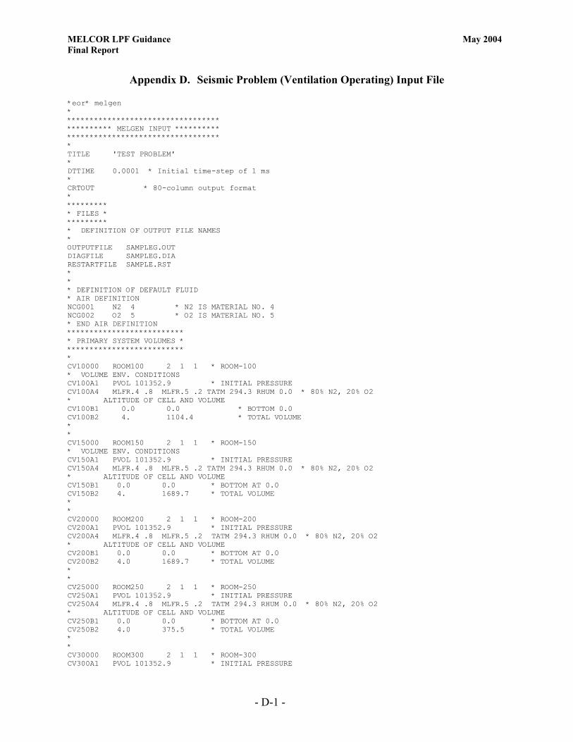
MELCOR LPF Guidance May 2004 Final Report
- D-1 -
Appendix D. Seismic Problem (Ventilation Operating) Input File *eor* melgen * ********************************** ********** MELGEN INPUT ********** ********************************** * TITLE 'TEST PROBLEM' * DTTIME 0.0001 * Initial time-step of 1 ms * CRTOUT * 80-column output format * ********* * FILES * ********* * DEFINITION OF OUTPUT FILE NAMES * OUTPUTFILE SAMPLEG.OUT DIAGFILE SAMPLEG.DIA RESTARTFILE SAMPLE.RST * * * DEFINITION OF DEFAULT FLUID * AIR DEFINITION NCG001 N2 4 * N2 IS MATERIAL NO. 4 NCG002 O2 5 * O2 IS MATERIAL NO. 5 * END AIR DEFINITION ************************** * PRIMARY SYSTEM VOLUMES * ************************** * CV10000 ROOM100 2 1 1 * ROOM-100 * VOLUME ENV. CONDITIONS CV100A1 PVOL 101352.9 * INITIAL PRESSURE CV100A4 MLFR.4 .8 MLFR.5 .2 TATM 294.3 RHUM 0.0 * 80% N2, 20% O2 * ALTITUDE OF CELL AND VOLUME CV100B1 0.0 0.0 * BOTTOM 0.0 CV100B2 4. 1104.4 * TOTAL VOLUME * * CV15000 ROOM150 2 1 1 * ROOM-150 * VOLUME ENV. CONDITIONS CV150A1 PVOL 101352.9 * INITIAL PRESSURE CV150A4 MLFR.4 .8 MLFR.5 .2 TATM 294.3 RHUM 0.0 * 80% N2, 20% O2 * ALTITUDE OF CELL AND VOLUME CV150B1 0.0 0.0 * BOTTOM AT 0.0 CV150B2 4. 1689.7 * TOTAL VOLUME * * CV20000 ROOM200 2 1 1 * ROOM-200 CV200A1 PVOL 101352.9 * INITIAL PRESSURE CV200A4 MLFR.4 .8 MLFR.5 .2 TATM 294.3 RHUM 0.0 * 80% N2, 20% O2 * ALTITUDE OF CELL AND VOLUME CV200B1 0.0 0.0 * BOTTOM AT 0.0 CV200B2 4.0 1689.7 * TOTAL VOLUME * * CV25000 ROOM250 2 1 1 * ROOM-250 CV250A1 PVOL 101352.9 * INITIAL PRESSURE CV250A4 MLFR.4 .8 MLFR.5 .2 TATM 294.3 RHUM 0.0 * 80% N2, 20% O2 * ALTITUDE OF CELL AND VOLUME CV250B1 0.0 0.0 * BOTTOM AT 0.0 CV250B2 4.0 375.5 * TOTAL VOLUME * * CV30000 ROOM300 2 1 1 * ROOM-300 CV300A1 PVOL 101352.9 * INITIAL PRESSURE

MELCOR LPF Guidance May 2004 Final Report
- D-2 -
CV300A4 MLFR.4 .8 MLFR.5 .2 TATM 294.3 RHUM 0.0 * 80% N2, 20% O2 * ALTITUDE OF CELL AND VOLUME CV300B1 0.0 0.0 * BOTTOM AT 0.0 CV300B2 4.0 828.3 * TOTAL VOLUME * * CV35000 ROOM350 2 1 1 * ROOM-350 CV350A1 PVOL 101352.9 * INITIAL PRESSURE CV350A4 MLFR.4 .8 MLFR.5 .2 TATM 294.3 RHUM 0.0 * 80% N2, 20% O2 * ALTITUDE OF CELL AND VOLUME CV350B1 0.0 0.0 * BOTTOM AT 0.0 CV350B2 4.0 1288.4 * TOTAL VOLUME * * CV40000 ROOM400 2 1 1 * ROOM-400 CV400A1 PVOL 101352.9 * INITIAL PRESSURE CV400A4 MLFR.4 .8 MLFR.5 .2 TATM 294.3 RHUM 0.0 * 80% N2, 20% O2 * ALTITUDE OF CELL AND VOLUME CV400B1 0.0 0.0 * BOTTOM AT 0.0 CV400B2 4.0 1159.6 * TOTAL VOLUME * * CV45000 ROOM450 2 1 1 * ROOM-400 CV450A1 PVOL 101352.9 * INITIAL PRESSURE CV450A4 MLFR.4 .8 MLFR.5 .2 TATM 294.3 RHUM 0.0 * 80% N2, 20% O2 * ALTITUDE OF CELL AND VOLUME CV450B1 0.0 0.0 * BOTTOM AT 0.0 CV450B2 4.0 368.1 * TOTAL VOLUME * * **************************************** * ENVIRONMENTAL VOLUME - OUTSIDE CELLS * **************************************** * CV50000 WEST-VOL500 2 1 1 * ENV-500 WEST CV500A1 PVOL 101351.6992 * INITIAL PRESSURE CV500A4 MLFR.4 .8 MLFR.5 .2 TATM 294.3 RHUM 0.0 * 80% N2, 20% O2 * ALTITUDE OF CELL AND VOLUME CV500B1 0.0 0.0 * BOTTOM AT 0.0 CV500B2 4.0 1.0E10 * TOTAL VOLUME * * CV60000 NORTH-VOL600 2 1 1 * ENV-600 NORTH CV600A1 PVOL 101351.8493 * INITIAL PRESSURE CV600A4 MLFR.4 .8 MLFR.5 .2 TATM 294.3 RHUM 0.0 * 80% N2, 20% O2 * ALTITUDE OF CELL AND VOLUME CV600B1 0.0 0.0 * BOTTOM AT 0.0 CV600B2 4.0 1.0E10 * TOTAL VOLUME * * * WIND FROM EAST AT 5 MPH CV70000 EAST-VOL700 2 1 1 * ENV-700 EAST CV700A1 PVOL 101355.0013 * INITIAL PRESSURE CV700A4 MLFR.4 .8 MLFR.5 .2 TATM 294.3 RHUM 0.0 * 80% N2, 20% O2 * ALTITUDE OF CELL AND VOLUME CV700B1 0.0 0.0 * BOTTOM AT 0.0 CV700B2 4.0 1.0E10 * TOTAL VOLUME * * CV80000 SOUTH-VOL800 2 1 1 * ENV-800 SOUTH CV800A1 PVOL 101351.8493 * INITIAL PRESSURE CV800A4 MLFR.4 .8 MLFR.5 .2 TATM 294.3 RHUM 0.0 * 80% N2, 20% O2 * ALTITUDE OF CELL AND VOLUME CV800B1 0.0 0.0 * BOTTOM AT 0.0 CV800B2 4.0 1.0E10 * TOTAL VOLUME * * * FILTER SYSTEM VOLUME CV90000 FILTER-VOL900 2 1 1 * FILTER VOLUME CV900A1 PVOL 101352.9 * INITIAL PRESSURE CV900A4 MLFR.4 .8 MLFR.5 .2 TATM 294.3 RHUM 0.0 * 80% N2, 20% O2

MELCOR LPF Guidance May 2004 Final Report
- D-3 -
* ALTITUDE OF CELL AND VOLUME CV900B1 0.0 0.0 * BOTTOM AT 0.0 CV900B2 4.0 1.0E10 * TOTAL VOLUME *********************** * INTERNAL FLOW PATHS * *********************** * Volumes Junct.Elev. * From To From To FL11000 100-300 100 300 1. 1. FL11001 0.0387 0.05 1.0 * A, L, FRACTION OPEN FL11003 1.5 1.5 * LOSS COEFFICIENT FL110S0 0.0387 0.0508 0.0254 * A, L, HYD.DIAM. * * * Volumes Junct.Elev. * From To From To FL11500 100-250 100 250 1. 1. FL11501 0.0387 0.05 1.0 * A, L, FRACTION OPEN FL11503 1.5 1.5 * LOSS COEFFICIENT FL115S0 0.0387 0.0508 0.0254 * A, L, HYD.DIAM. * * * Volumes Junct.Elev. * From To From To FL12000 150-100 150 100 1. 1. FL12001 0.0387 0.05 1.0 * A, L, FRACTION OPEN FL12003 1.5 1.5 * LOSS COEFFICIENT FL120S0 0.0387 0.0508 0.0254 * A, L, HYD.DIAM. * * * Volumes Junct.Elev. * From To From To FL12500 300-350 300 350 1. 1. FL12501 0.0387 0.05 1.0 * A, L, FRACTION OPEN FL12503 1.5 1.5 * LOSS COEFFICIENT FL125S0 0.0387 0.0508 0.0254 * A, L, HYD.DIAM. * * * Volumes Junct.Elev. * From To From To FL13000 150-250 150 250 1. 1. FL13001 0.0387 0.05 1.0 * A, L, FRACTION OPEN FL13003 1.5 1.5 * LOSS COEFFICIENT FL130S0 0.0387 0.0508 0.0254 * A, L, HYD.DIAM. * * * Volumes Junct.Elev. * From To From To FL13500 150-200 150 200 1. 1. FL13501 0.0387 0.05 1.0 * A, L, FRACTION OPEN FL13503 1.5 1.5 * LOSS COEFFICIENT FL135S0 0.0387 0.0508 0.0254 * A, L, HYD.DIAM. * * * Volumes Junct.Elev. * From To From To FL14000 200-250 200 250 1. 1. FL14001 0.0387 0.05 1.0 * A, L, FRACTION OPEN FL14003 1.5 1.5 * LOSS COEFFICIENT FL140S0 0.0387 0.0508 0.0254 * A, L, HYD.DIAM. * * * Volumes Junct.Elev. * From To From To FL14500 250-350 250 350 1. 1. FL14501 0.0387 0.05 1.0 * A, L, FRACTION OPEN FL14503 1.5 1.5 * LOSS COEFFICIENT FL145S0 0.0387 0.0508 0.0254 * A, L, HYD.DIAM. * * * Volumes Junct.Elev.

MELCOR LPF Guidance May 2004 Final Report
- D-4 -
* From To From To FL15000 250-400 250 400 1. 1. FL15001 0.0387 0.05 1.0 * A, L, FRACTION OPEN FL15003 1.5 1.5 * LOSS COEFFICIENT FL150S0 0.0387 0.0508 0.0254 * A, L, HYD.DIAM. * * * Volumes Junct.Elev. * From To From To FL15500 350-400 350 400 1. 1. FL15501 0.0387 0.05 1.0 * A, L, FRACTION OPEN FL15503 1.5 1.5 * LOSS COEFFICIENT FL155S0 0.0387 0.0508 0.0254 * A, L, HYD.DIAM. * * * Volumes Junct.Elev. * From To From To FL16000 350-450 350 450 1. 1. FL16001 0.0387 0.05 1.0 * A, L, FRACTION OPEN FL16003 1.5 1.5 * LOSS COEFFICIENT FL160S0 0.0387 0.0508 0.0254 * A, L, HYD.DIAM. * * * Volumes Junct.Elev. * From To From To FL16500 450-400 450 400 1. 1. FL16501 0.0387 0.05 1.0 * A, L, FRACTION OPEN FL16503 1.5 1.5 * LOSS COEFFICIENT FL165S0 0.0387 0.0508 0.0254 * A, L, HYD.DIAM. * * ********************************** * FLOW PATHS FROM/TO EXTERNAL VOLUMES * ********************************** * Volumes Junct.Elev. * From To From To FL17000 300-500 300 500 1. 1. FL17001 0.0639 0.05 1.0 * A, L, FRACTION OPEN FL17003 1.5 1.5 * LOSS COEFFICIENT FL170S0 0.0639 0.0508 0.0254 * A, L, HYD.DIAM. * * * Volumes Junct.Elev. * From To From To FL17500 200-600 200 600 1. 1. FL17501 0.0639 0.05 1.0 * A, L, FRACTION OPEN FL17503 1.5 1.5 * LOSS COEFFICIENT FL175S0 0.0639 0.0508 0.0254 * A, L, HYD.DIAM. * * * Volumes Junct.Elev. * From To From To FL18000 400-700 400 700 1. 1. FL18001 0.0639 0.05 1.0 * A, L, FRACTION OPEN FL18003 1.5 1.5 * LOSS COEFFICIENT FL180S0 0.0639 0.0508 0.0254 * A, L, HYD.DIAM. * * * Volumes Junct.Elev. * From To From To FL18500 450-800 450 800 1. 1. FL18501 3.9 0.05 1.0 * A, L, FRACTION OPEN FL18503 1.5 1.5 * LOSS COEFFICIENT FL185S0 3.9 0.0508 1.6 * A, L, HYD.DIAM. FL185V0 -1 251 251 * USE A CONTROL FUNCTION CF25100 'JUN CONROL' TAB-FUN 1 1.0 * TRIP ON TIME CF25101 0.0 CF25103 233 * TAB FUNCTION NUMBER CF25110 1.0 0.0 TIME * TAB FUNCTION NEXT

MELCOR LPF Guidance May 2004 Final Report
- D-5 -
TF23300 'MOD DOOR' 6 1.0 0. TF23310 0.0 0.0164 TF23311 120. 0.0164 TF23312 120. 1.0 TF23313 720. 1.0 TF23314 720. 0.0164 TF23315 200000. 0.0164 * * VENTILATION SUPPLY WALL OPENING * Volumes Junct.Elev. * From To From To FL19000 700-200 700 200 1. 1. FL19001 2.0 0.05 1.0 * A, L, FRACTION OPEN FL19003 1.5 1.5 * LOSS COEFFICIENT FL190S0 2.0 0.3048 2.0 * A, L, HYD.DIAM. * ******************** * TO FILTER SYSTEM * ******************** * * FIXED FLOW CONDITION TO FILTER SYSTEM * Volumes Junct.Elev. * From To From To FL20100 100-900 100 900 1. 1. FL20101 1.0 0.05 1.0 * A, L, FRACTION OPEN FL201S0 1.0 0.3048 1.0 * A, L, HYD.DIAM. FL201T0 1 201 TF20100 'FIXED FLOW' 3 1.0 0.0 TF20110 0. 1.226 TF20111 10. 1.226 TF20112 500000. 1.226 * * * Volumes Junct.Elev. * From To From To FL20200 150-900 150 900 1. 1. FL20201 1.0 0.05 1.0 * A, L, FRACTION OPEN FL202S0 1.0 0.3048 1.0 * A, L, HYD.DIAM. FL202T0 1 202 TF20200 'FIXED FLOW' 3 1.0 0.0 TF20210 0. 1.876 TF20211 10. 1.876 TF20212 500000. 1.876 * * * Volumes Junct.Elev. * From To From To FL20300 200-900 200 900 1. 1. FL20301 1.0 0.05 1.0 * A, L, FRACTION OPEN FL203S0 1.0 0.3048 1.0 * A, L, HYD.DIAM. FL203T0 1 203 TF20300 'FIXED FLOW' 3 1.0 0.0 TF20310 0. 1.876 TF20311 10. 1.876 TF20312 500000. 1.876 * * * Volumes Junct.Elev. * From To From To FL20400 250-900 250 900 1. 1. FL20401 1.0 0.05 1.0 * A, L, FRACTION OPEN FL204S0 1.0 0.3048 1.0 * A, L, HYD.DIAM. FL204T0 1 204 TF20400 'FIXED FLOW' 3 1.0 0.0 TF20410 0. 0.417 TF20411 10. 0.417 TF20412 500000. 0.417 * * * Volumes Junct.Elev. * From To From To

MELCOR LPF Guidance May 2004 Final Report
- D-6 -
FL20500 300-900 300 900 1. 1. FL20501 1.0 0.05 1.0 * A, L, FRACTION OPEN FL205S0 1.0 0.3048 1.0 * A, L, HYD.DIAM. FL205T0 1 205 TF20500 'FIXED FLOW' 3 1.0 0.0 TF20510 0. 0.919 TF20511 10. 0.919 TF20512 500000. 0.919 * * * Volumes Junct.Elev. * From To From To FL20600 350-900 350 900 1. 1. FL20601 1.0 0.05 1.0 * A, L, FRACTION OPEN FL206S0 1.0 0.3048 1.0 * A, L, HYD.DIAM. FL206T0 1 206 TF20600 'FIXED FLOW' 3 1.0 0.0 TF20610 0. 1.430 TF20611 10. 1.430 TF20612 500000. 1.430 * * * Volumes Junct.Elev. * From To From To FL20700 400-900 400 900 1. 1. FL20701 1.0 0.05 1.0 * A, L, FRACTION OPEN FL207S0 1.0 0.3048 1.0 * A, L, HYD.DIAM. FL207T0 1 207 TF20700 'FIXED FLOW' 3 1.0 0.0 TF20710 0. 1.287 TF20711 10. 1.287 TF20712 500000. 1.287 * * * Volumes Junct.Elev. * From To From To FL20800 450-900 450 900 1. 1. FL20801 1.0 0.05 1.0 * A, L, FRACTION OPEN FL208S0 1.0 0.3048 1.0 * A, L, HYD.DIAM. FL208T0 1 208 TF20800 'FIXED FLOW' 3 1.0 0.0 TF20810 0. 0.409 TF20811 10. 0.409 TF20812 500000. 0.409 * * ************************* * HEAT STRUCTURES INPUT * ************************* * * * HS10001000 3 1 * 3 NODES, RECTANGULAR GEOMETRY HS10001001 'FLOOR 100' * STRUCTURE NAME HS10001002 0.0 0.0 * BOTTOM AT 0.0 M, HORIZONTAL HS10001100 -1 1 0.0 * DEFINE NODE POSITIONS, FIRST AT 0.0 M HS10001101 0.3048 3 * THIRD NODE NODE AT 0.3048 M HS10001200 -1 * DEFINE MATERIAL HS10001201 'CONCRETE' 2 * 2 MESH POINTS HS10001300 0 * NO INTERNAL POWER SOURCE HS10001400 0 * ADIABATIC LOWER BC HS10001600 1 100 EXT 0.0 0.0 * UPPER BC * Area Char.L Width * EXTernal heat transfer HS10001700 278.7 20.0 20.0 * SUFRACE AREA M**2 * HS10002000 3 1 HS10002001 'CEILING 100' HS10002002 4.0 0.0 * Bottom NB HS10002100 -1 1 0.0 HS10002101 0.3048 3 HS10002200 -1

MELCOR LPF Guidance May 2004 Final Report
- D-7 -
HS10002201 'CONCRETE' 2 HS10002300 0 HS10002400 1 100 EXT 0.0 0.0 * Area Char.L Width HS10002500 278.7 5.0 5.0 HS10002600 0 * HS10003000 3 1 HS10003001 'WALL 100' HS10003002 0.0 1.0 * BOTTOM AT 0.0 M, VERTICAL HS10003100 -1 1 0.0 HS10003101 0.3048 3 HS10003200 -1 HS10003201 'CONCRETE' 2 HS10003300 0 HS10003400 1 100 EXT 0.0 0.0 * Area Char.L Width HS10003500 265.7 3.0 3.0 HS10003600 1 300 EXT 0.0 0.0 * Area Char.L Width HS10003700 265.7 3.0 3.0 * * * HS15001000 3 1 * 3 NODES, RECTANGULAR GEOMETRY HS15001001 'FLOOR 150' * STRUCTURE NAME HS15001002 0.0 0.0 * BOTTOM AT 0.0 M, HORIZONTAL HS15001100 -1 1 0.0 * DEFINE NODE POSITIONS, FIRST AT 0.0 M HS15001101 0.3048 3 * THIRD NODE NODE AT 0.3048 M HS15001200 -1 * DEFINE MATERIAL HS15001201 'CONCRETE' 2 * 2 MESH POINTS HS15001300 0 * NO INTERNAL POWER SOURCE HS15001400 0 * ADIABATIC LOWER BC HS15001600 1 150 EXT 0.0 0.0 * UPPER BC * Area Char.L Width * EXTernal heat transfer HS15001700 426.4 20.0 20.0 * SUFRACE AREA M**2 * HS15002000 3 1 HS15002001 'CEILING 150' HS15002002 4.0 0.0 * Bottom NB HS15002100 -1 1 0.0 HS15002101 0.3048 3 HS15002200 -1 HS15002201 'CONCRETE' 2 HS15002300 0 HS15002400 1 150 EXT 0.0 0.0 * Area Char.L Width HS15002500 426.4 5.0 5.0 HS15002600 0 * HS15003000 3 1 HS15003001 'WALL 150' HS15003002 0.0 1.0 * BOTTOM AT 0.0 M, VERTICAL HS15003100 -1 1 0.0 HS15003101 0.3048 3 HS15003200 -1 HS15003201 'CONCRETE' 2 HS15003300 0 HS15003400 1 150 EXT 0.0 0.0 * Area Char.L Width HS15003500 335.8 3.0 3.0 HS15003600 1 300 EXT 0.0 0.0 * Area Char.L Width HS15003700 335.8 3.0 3.0 * * * HS20001000 3 1 * 3 NODES, RECTANGULAR GEOMETRY HS20001001 'FLOOR 200' * STRUCTURE NAME HS20001002 0.0 0.0 * BOTTOM AT 0.0 M, HORIZONTAL HS20001100 -1 1 0.0 * DEFINE NODE POSITIONS, FIRST AT 0.0 M

MELCOR LPF Guidance May 2004 Final Report
- D-8 -
HS20001101 0.3048 3 * THIRD NODE NODE AT 0.3048 M HS20001200 -1 * DEFINE MATERIAL HS20001201 'CONCRETE' 2 * 2 MESH POINTS HS20001300 0 * NO INTERNAL POWER SOURCE HS20001400 0 * ADIABATIC LOWER BC HS20001600 1 200 EXT 0.0 0.0 * UPPER BC * Area Char.L Width * EXTernal heat transfer HS20001700 426.4 20.0 20.0 * SUFRACE AREA M**2 * HS20002000 3 1 HS20002001 'CEILING 200' HS20002002 4.0 0.0 * Bottom NB HS20002100 -1 1 0.0 HS20002101 0.3048 3 HS20002200 -1 HS20002201 'CONCRETE' 2 HS20002300 0 HS20002400 1 200 EXT 0.0 0.0 * Area Char.L Width HS20002500 426.4 5.0 5.0 HS20002600 0 * HS20003000 3 1 HS20003001 'WALL 200' HS20003002 0.0 1.0 * BOTTOM AT 0.0 M, VERTICAL HS20003100 -1 1 0.0 HS20003101 0.3048 3 HS20003200 -1 HS20003201 'CONCRETE' 2 HS20003300 0 HS20003400 1 200 EXT 0.0 0.0 * Area Char.L Width HS20003500 335.8 3.0 3.0 HS20003600 1 300 EXT 0.0 0.0 * Area Char.L Width HS20003700 335.8 3.0 3.0 * * * HS25001000 3 1 * 3 NODES, RECTANGULAR GEOMETRY HS25001001 'FLOOR 250' * STRUCTURE NAME HS25001002 0.0 0.0 * BOTTOM AT 0.0 M, HORIZONTAL HS25001100 -1 1 0.0 * DEFINE NODE POSITIONS, FIRST AT 0.0 M HS25001101 0.3048 3 * THIRD NODE NODE AT 0.3048 M HS25001200 -1 * DEFINE MATERIAL HS25001201 'CONCRETE' 2 * 2 MESH POINTS HS25001300 0 * NO INTERNAL POWER SOURCE HS25001400 0 * ADIABATIC LOWER BC HS25001600 1 250 EXT 0.0 0.0 * UPPER BC * Area Char.L Width * EXTernal heat transfer HS25001700 94.8 20.0 20.0 * SUFRACE AREA M**2 * HS25002000 3 1 HS25002001 'CEILING 250' HS25002002 4.0 0.0 * Bottom NB HS25002100 -1 1 0.0 HS25002101 0.3048 3 HS25002200 -1 HS25002201 'CONCRETE' 2 HS25002300 0 HS25002400 1 250 EXT 0.0 0.0 * Area Char.L Width HS25002500 94.8 5.0 5.0 HS25002600 0 * HS25003000 3 1 HS25003001 'WALL 250' HS25003002 0.0 1.0 * BOTTOM AT 0.0 M, VERTICAL HS25003100 -1 1 0.0 HS25003101 0.3048 3 HS25003200 -1
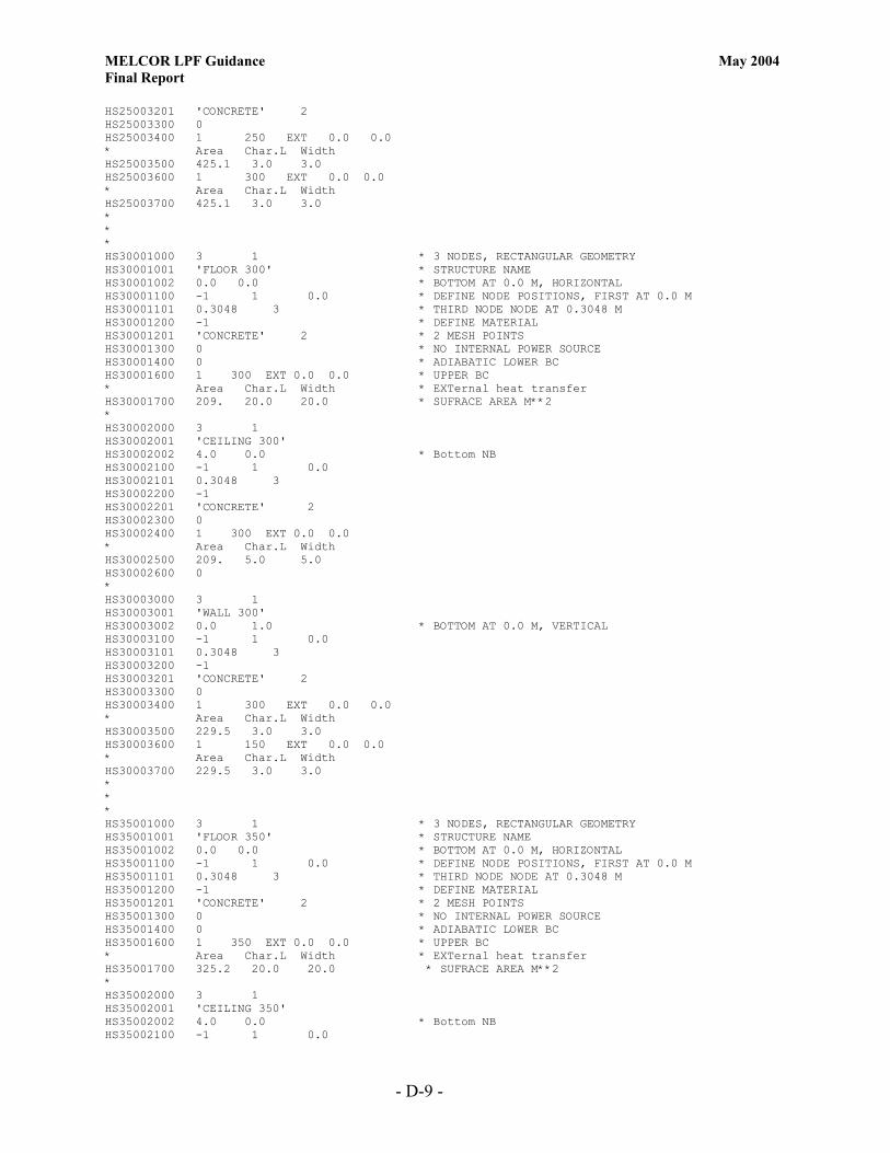
MELCOR LPF Guidance May 2004 Final Report
- D-9 -
HS25003201 'CONCRETE' 2 HS25003300 0 HS25003400 1 250 EXT 0.0 0.0 * Area Char.L Width HS25003500 425.1 3.0 3.0 HS25003600 1 300 EXT 0.0 0.0 * Area Char.L Width HS25003700 425.1 3.0 3.0 * * * HS30001000 3 1 * 3 NODES, RECTANGULAR GEOMETRY HS30001001 'FLOOR 300' * STRUCTURE NAME HS30001002 0.0 0.0 * BOTTOM AT 0.0 M, HORIZONTAL HS30001100 -1 1 0.0 * DEFINE NODE POSITIONS, FIRST AT 0.0 M HS30001101 0.3048 3 * THIRD NODE NODE AT 0.3048 M HS30001200 -1 * DEFINE MATERIAL HS30001201 'CONCRETE' 2 * 2 MESH POINTS HS30001300 0 * NO INTERNAL POWER SOURCE HS30001400 0 * ADIABATIC LOWER BC HS30001600 1 300 EXT 0.0 0.0 * UPPER BC * Area Char.L Width * EXTernal heat transfer HS30001700 209. 20.0 20.0 * SUFRACE AREA M**2 * HS30002000 3 1 HS30002001 'CEILING 300' HS30002002 4.0 0.0 * Bottom NB HS30002100 -1 1 0.0 HS30002101 0.3048 3 HS30002200 -1 HS30002201 'CONCRETE' 2 HS30002300 0 HS30002400 1 300 EXT 0.0 0.0 * Area Char.L Width HS30002500 209. 5.0 5.0 HS30002600 0 * HS30003000 3 1 HS30003001 'WALL 300' HS30003002 0.0 1.0 * BOTTOM AT 0.0 M, VERTICAL HS30003100 -1 1 0.0 HS30003101 0.3048 3 HS30003200 -1 HS30003201 'CONCRETE' 2 HS30003300 0 HS30003400 1 300 EXT 0.0 0.0 * Area Char.L Width HS30003500 229.5 3.0 3.0 HS30003600 1 150 EXT 0.0 0.0 * Area Char.L Width HS30003700 229.5 3.0 3.0 * * * HS35001000 3 1 * 3 NODES, RECTANGULAR GEOMETRY HS35001001 'FLOOR 350' * STRUCTURE NAME HS35001002 0.0 0.0 * BOTTOM AT 0.0 M, HORIZONTAL HS35001100 -1 1 0.0 * DEFINE NODE POSITIONS, FIRST AT 0.0 M HS35001101 0.3048 3 * THIRD NODE NODE AT 0.3048 M HS35001200 -1 * DEFINE MATERIAL HS35001201 'CONCRETE' 2 * 2 MESH POINTS HS35001300 0 * NO INTERNAL POWER SOURCE HS35001400 0 * ADIABATIC LOWER BC HS35001600 1 350 EXT 0.0 0.0 * UPPER BC * Area Char.L Width * EXTernal heat transfer HS35001700 325.2 20.0 20.0 * SUFRACE AREA M**2 * HS35002000 3 1 HS35002001 'CEILING 350' HS35002002 4.0 0.0 * Bottom NB HS35002100 -1 1 0.0

MELCOR LPF Guidance May 2004 Final Report
- D-10 -
HS35002101 0.3048 3 HS35002200 -1 HS35002201 'CONCRETE' 2 HS35002300 0 HS35002400 1 350 EXT 0.0 0.0 * Area Char.L Width HS35002500 325.2 5.0 5.0 HS35002600 0 * HS35003000 3 1 HS35003001 'WALL 350' HS35003002 0.0 1.0 * BOTTOM AT 0.0 M, VERTICAL HS35003100 -1 1 0.0 HS35003101 0.3048 3 HS35003200 -1 HS35003201 'CONCRETE' 2 HS35003300 0 HS35003400 1 350 EXT 0.0 0.0 * Area Char.L Width HS35003500 326.1 3.0 3.0 HS35003600 1 150 EXT 0.0 0.0 * Area Char.L Width HS35003700 326.1 3.0 3.0 * * * HS40001000 3 1 * 3 NODES, RECTANGULAR GEOMETRY HS40001001 'FLOOR 400' * STRUCTURE NAME HS40001002 0.0 0.0 * BOTTOM AT 0.0 M, HORIZONTAL HS40001100 -1 1 0.0 * DEFINE NODE POSITIONS, FIRST AT 0.0 M HS40001101 0.3048 3 * THIRD NODE NODE AT 0.3048 M HS40001200 -1 * DEFINE MATERIAL HS40001201 'CONCRETE' 2 * 2 MESH POINTS HS40001300 0 * NO INTERNAL POWER SOURCE HS40001400 0 * ADIABATIC LOWER BC HS40001600 1 400 EXT 0.0 0.0 * UPPER BC * Area Char.L Width * EXTernal heat transfer HS40001700 292.6 20.0 20.0 * SUFRACE AREA M**2 * HS40002000 3 1 HS40002001 'CEILING 400' HS40002002 4.0 0.0 * Bottom NB HS40002100 -1 1 0.0 HS40002101 0.3048 3 HS40002200 -1 HS40002201 'CONCRETE' 2 HS40002300 0 HS40002400 1 400 EXT 0.0 0.0 * Area Char.L Width HS40002500 292.6 5.0 5.0 HS40002600 0 * HS40003000 3 1 HS40003001 'WALL 400' HS40003002 0.0 1.0 * BOTTOM AT 0.0 M, VERTICAL HS40003100 -1 1 0.0 HS40003101 0.3048 3 HS40003200 -1 HS40003201 'CONCRETE' 2 HS40003300 0 HS40003400 1 400 EXT 0.0 0.0 * Area Char.L Width HS40003500 277.8 3.0 3.0 HS40003600 1 150 EXT 0.0 0.0 * Area Char.L Width HS40003700 277.8 3.0 3.0 * * * HS45001000 3 1 * 3 NODES, RECTANGULAR GEOMETRY HS45001001 'FLOOR 450' * STRUCTURE NAME

MELCOR LPF Guidance May 2004 Final Report
- D-11 -
HS45001002 0.0 0.0 * BOTTOM AT 0.0 M, HORIZONTAL HS45001100 -1 1 0.0 * DEFINE NODE POSITIONS, FIRST AT 0.0 M HS45001101 0.3048 3 * THIRD NODE NODE AT 0.3048 M HS45001200 -1 * DEFINE MATERIAL HS45001201 'CONCRETE' 2 * 2 MESH POINTS HS45001300 0 * NO INTERNAL POWER SOURCE HS45001400 0 * ADIABATIC LOWER BC HS45001600 1 450 EXT 0.0 0.0 * UPPER BC * Area Char.L Width * EXTernal heat transfer HS45001700 92.9 20.0 20.0 * SUFRACE AREA M**2 * HS45002000 3 1 HS45002001 'CEILING 450' HS45002002 4.0 0.0 * Bottom NB HS45002100 -1 1 0.0 HS45002101 0.3048 3 HS45002200 -1 HS45002201 'CONCRETE' 2 HS45002300 0 HS45002400 1 450 EXT 0.0 0.0 * Area Char.L Width HS45002500 92.9 5.0 5.0 HS45002600 0 * HS45003000 3 1 HS45003001 'WALL 450' HS45003002 0.0 1.0 * BOTTOM AT 0.0 M, VERTICAL HS45003100 -1 1 0.0 HS45003101 0.3048 3 HS45003200 -1 HS45003201 'CONCRETE' 2 HS45003300 0 HS45003400 1 450 EXT 0.0 0.0 * Area Char.L Width HS45003500 265.7 3.0 3.0 HS45003600 1 150 EXT 0.0 0.0 * Area Char.L Width HS45003700 265.7 3.0 3.0 * * * HS50001000 3 1 HS50001001 'FLOOR 500' HS50001002 0.0 0.0 HS50001100 -1 1 0.0 HS50001101 0.3 3 HS50001200 -1 HS50001201 'CONCRETE' 2 HS50001300 0 HS50001400 0 HS50001600 1 500 EXT 0.0 0.0 HS50001700 0.0001 0.0001 0.0001 * AREA * * * HS60001000 3 1 HS60001001 'FLOOR 600' HS60001002 0.0 0.0 HS60001100 -1 1 0.0 HS60001101 0.3 3 HS60001200 -1 HS60001201 'CONCRETE' 2 HS60001300 0 HS60001400 0 HS60001600 1 600 EXT 0.0 0.0 HS60001700 0.0001 0.0001 0.0001 * AREA * * * HS70001000 3 1 HS70001001 'FLOOR 700'

MELCOR LPF Guidance May 2004 Final Report
- D-12 -
HS70001002 0.0 0.0 HS70001100 -1 1 0.0 HS70001101 0.3 3 HS70001200 -1 HS70001201 'CONCRETE' 2 HS70001300 0 HS70001400 0 HS70001600 1 700 EXT 0.0 0.0 HS70001700 0.0001 0.0001 0.0001 * AREA * * * HS80001000 3 1 HS80001001 'FLOOR 800' HS80001002 0.0 0.0 HS80001100 -1 1 0.0 HS80001101 0.3 3 HS80001200 -1 HS80001201 'CONCRETE' 2 HS80001300 0 HS80001400 0 HS80001600 1 800 EXT 0.0 0.0 HS80001700 0.0001 0.0001 0.0001 * AREA * HS90001000 3 1 HS90001001 'FLOOR 900' HS90001002 0.0 0.0 HS90001100 -1 1 0.0 HS90001101 0.3 3 HS90001200 -1 HS90001201 'CONCRETE' 2 HS90001300 0 HS90001400 0 HS90001600 1 900 EXT 0.0 0.0 HS90001700 0.0001 0.0001 0.0001 * AREA * * AEROSOL SECTION RN1000 0 * ACTIVATE RNCA100 0 * NOT ACTIVE * RN1001 20 2 17 0 0 1 0 RN1100 1.0e-8 3.0e-6 11.46e+3 RNACOEF 1 * RNAS000 350 2 1 1. 1.0 601 2 RNAS001 2.3e-6 2. * DEFINE TABULAR FUNCTION AEROSOL RELEASE RATE * TF60100 'AEROSOL' 5 1.0 TF60110 0.0 0.000 * TIME 1 KG RELEASE TF60111 10.0 0.000 TF60112 11.0 1.0 TF60113 12.0 0.0 TF60114 200000. 0.0 . *eor* melcor * ********************************** * MELCOR INPUT * ********************************** * TITLE 'TEST PROBLEM' * RESTART 0 * RESTART FROM CYCLE 0 * TEND 72000.0 * END TIME S * CPULIM 100000.0 CPULEFT 20.0 *
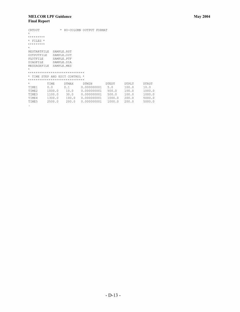
MELCOR LPF Guidance May 2004 Final Report
- D-13 -
CRTOUT * 80-COLUMN OUTPUT FORMAT * ********* * FILES * ********* * RESTARTFILE SAMPLE.RST OUTPUTFILE SAMPLE.OUT PLOTFILE SAMPLE.PTF DIAGFILE SAMPLE.DIA MESSAGEFILE SAMPLE.MES * ****************************** * TIME STEP AND EDIT CONTROL * ****************************** * TIME DTMAX DTMIN DTEDT DTPLT DTRST TIME1 0.0 0.1 0.000000001 5.0 100.0 10.0 TIME2 1000.0 10.0 0.000000001 500.0 100.0 1000.0 TIME3 1100.0 30.0 0.000000001 500.0 100.0 1000.0 TIME4 1300.0 100.0 0.000000001 1000.0 200.0 5000.0 TIME5 2500.0 200.0 0.000000001 1000.0 200.0 5000.0 .

MELCOR LPF Guidance May 2004 Final Report
E-1
Appendix E. Fire Problem Input File *eor* melgen * ********************************** ********** MELGEN INPUT ********** ********************************** * TITLE 'TEST PROBLEM' * DTTIME 0.001 * Initial time-step of 1 ms * CRTOUT * 80-column output format * ********* * FILES * ********* * DEFINITION OF OUTPUT FILE NAMES * OUTPUTFILE SAMPLEG.OUT DIAGFILE SAMPLEG.DIA RESTARTFILE SAMPLE.RST * * * DEFINITION OF DEFAULT FLUID * AIR DEFINITION NCG001 N2 4 * N2 IS MATERIAL NO. 4 NCG002 O2 5 * O2 IS MATERIAL NO. 5 * END AIR DEFINITION ************************** * PRIMARY SYSTEM VOLUMES * ************************** * CV10000 ROOM100 2 1 1 * ROOM-100 * VOLUME ENV. CONDITIONS CV100A1 PVOL 101352.9 * INITIAL PRESSURE CV100A4 MLFR.4 .8 MLFR.5 .2 TATM 294.3 RHUM 0.0 * 80% N2, 20% O2 * ALTITUDE OF CELL AND VOLUME CV100B1 0.0 0.0 * BOTTOM 0.0 CV100B2 4. 1104.4 * TOTAL VOLUME * * CV15000 ROOM150 2 1 1 * ROOM-150 * VOLUME ENV. CONDITIONS CV150A1 PVOL 101352.9 * INITIAL PRESSURE CV150A4 MLFR.4 .8 MLFR.5 .2 TATM 294.3 RHUM 0.0 * 80% N2, 20% O2 * ALTITUDE OF CELL AND VOLUME CV150B1 0.0 0.0 * BOTTOM AT 0.0 CV150B2 4. 1689.7 * TOTAL VOLUME * * CV20000 ROOM200 2 1 1 * ROOM-200 CV200A1 PVOL 101352.9 * INITIAL PRESSURE CV200A4 MLFR.4 .8 MLFR.5 .2 TATM 294.3 RHUM 0.0 * 80% N2, 20% O2 * ALTITUDE OF CELL AND VOLUME CV200B1 0.0 0.0 * BOTTOM AT 0.0 CV200B2 4.0 1689.7 * TOTAL VOLUME * * CV25000 ROOM250 2 1 1 * ROOM-250 CV250A1 PVOL 101352.9 * INITIAL PRESSURE CV250A4 MLFR.4 .8 MLFR.5 .2 TATM 294.3 RHUM 0.0 * 80% N2, 20% O2 * ALTITUDE OF CELL AND VOLUME CV250B1 0.0 0.0 * BOTTOM AT 0.0 CV250B2 4.0 375.5 * TOTAL VOLUME * * CV30000 ROOM300 2 1 1 * ROOM-300 CV300A1 PVOL 101352.9 * INITIAL PRESSURE
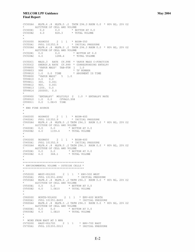
MELCOR LPF Guidance May 2004 Final Report
E-2
CV300A4 MLFR.4 .8 MLFR.5 .2 TATM 294.3 RHUM 0.0 * 80% N2, 20% O2 * ALTITUDE OF CELL AND VOLUME CV300B1 0.0 0.0 * BOTTOM AT 0.0 CV300B2 4.0 828.3 * TOTAL VOLUME * * CV35000 ROOM350 2 1 1 * ROOM-350 CV350A1 PVOL 101352.9 * INITIAL PRESSURE CV350A4 MLFR.4 .8 MLFR.5 .2 TATM 294.3 RHUM 0.0 * 80% N2, 20% O2 * ALTITUDE OF CELL AND VOLUME CV350B1 0.0 0.0 * BOTTOM AT 0.0 CV350B2 4.0 1288.4 * TOTAL VOLUME CV350C1 MASS.3 RATE CF.998 * VAPOR MASS C-FUNCTION CV350C2 ENERGY.A RATE CF.999 * CORRESPONDING ENTALPY CF99800 'VAPOR MASS' TAB-FUN 1 1.0 CF99803 998 * TF NUMBER CF99810 1.0 0.0 TIME * ARGUMENT IS TIME TF99800 'VAPOR MASS' 5 1.0 TF99810 0.0 0.0 TF99811 300. 0.001 TF99812 900. 0.001 TF99813 1200. 0.0 TF99814 200000. 0.0 * CF99900 'ENTHALPY' MULTIPLY 2 1.0 * ENTHALPY RATE CF99910 1.0 0.0 CFVALU.998 CF99911 0.0 1.0E+9 TIME * * END FIRE SOURCE * * CV40000 ROOM400 2 1 1 * ROOM-400 CV400A1 PVOL 101352.9 * INITIAL PRESSURE CV400A4 MLFR.4 .8 MLFR.5 .2 TATM 294.3 RHUM 0.0 * 80% N2, 20% O2 * ALTITUDE OF CELL AND VOLUME CV400B1 0.0 0.0 * BOTTOM AT 0.0 CV400B2 4.0 1159.6 * TOTAL VOLUME * * CV45000 ROOM450 2 1 1 * ROOM-400 CV450A1 PVOL 101352.9 * INITIAL PRESSURE CV450A4 MLFR.4 .8 MLFR.5 .2 TATM 294.3 RHUM 0.0 * 80% N2, 20% O2 * ALTITUDE OF CELL AND VOLUME CV450B1 0.0 0.0 * BOTTOM AT 0.0 CV450B2 4.0 368.1 * TOTAL VOLUME * * **************************************** * ENVIRONMENTAL VOLUME - OUTSIDE CELLS * **************************************** * CV50000 WEST-VOL500 2 1 1 * ENV-500 WEST CV500A1 PVOL 101351.6992 * INITIAL PRESSURE CV500A4 MLFR.4 .8 MLFR.5 .2 TATM 294.3 RHUM 0.0 * 80% N2, 20% O2 * ALTITUDE OF CELL AND VOLUME CV500B1 0.0 0.0 * BOTTOM AT 0.0 CV500B2 4.0 1.0E10 * TOTAL VOLUME * * CV60000 NORTH-VOL600 2 1 1 * ENV-600 NORTH CV600A1 PVOL 101351.8493 * INITIAL PRESSURE CV600A4 MLFR.4 .8 MLFR.5 .2 TATM 294.3 RHUM 0.0 * 80% N2, 20% O2 * ALTITUDE OF CELL AND VOLUME CV600B1 0.0 0.0 * BOTTOM AT 0.0 CV600B2 4.0 1.0E10 * TOTAL VOLUME * * * WIND FROM EAST AT 5 MPH CV70000 EAST-VOL700 2 1 1 * ENV-700 EAST CV700A1 PVOL 101355.0013 * INITIAL PRESSURE

MELCOR LPF Guidance May 2004 Final Report
E-3
CV700A4 MLFR.4 .8 MLFR.5 .2 TATM 294.3 RHUM 0.0 * 80% N2, 20% O2 * ALTITUDE OF CELL AND VOLUME CV700B1 0.0 0.0 * BOTTOM AT 0.0 CV700B2 4.0 1.0E10 * TOTAL VOLUME * * CV80000 SOUTH-VOL800 2 1 1 * ENV-800 SOUTH CV800A1 PVOL 101351.8493 * INITIAL PRESSURE CV800A4 MLFR.4 .8 MLFR.5 .2 TATM 294.3 RHUM 0.0 * 80% N2, 20% O2 * ALTITUDE OF CELL AND VOLUME CV800B1 0.0 0.0 * BOTTOM AT 0.0 CV800B2 4.0 1.0E10 * TOTAL VOLUME * * * *********************** * INTERNAL FLOW PATHS * *********************** * Volumes Junct.Elev. * From To From To FL11000 100-300 100 300 1. 1. FL11001 0.0387 0.05 1.0 * A, L, FRACTION OPEN FL11003 1.5 1.5 * LOSS COEFFICIENT FL110S0 0.0387 0.0508 0.0254 * A, L, HYD.DIAM. * * * Volumes Junct.Elev. * From To From To FL11500 100-250 100 250 1. 1. FL11501 0.0387 0.05 1.0 * A, L, FRACTION OPEN FL11503 1.5 1.5 * LOSS COEFFICIENT FL115S0 0.0387 0.0508 0.0254 * A, L, HYD.DIAM. * * * Volumes Junct.Elev. * From To From To FL12000 150-100 150 100 1. 1. FL12001 0.0387 0.05 1.0 * A, L, FRACTION OPEN FL12003 1.5 1.5 * LOSS COEFFICIENT FL120S0 0.0387 0.0508 0.0254 * A, L, HYD.DIAM. * * * Volumes Junct.Elev. * From To From To FL12500 300-350 300 350 1. 1. FL12501 0.0387 0.05 1.0 * A, L, FRACTION OPEN FL12503 1.5 1.5 * LOSS COEFFICIENT FL125S0 0.0387 0.0508 0.0254 * A, L, HYD.DIAM. * * * Volumes Junct.Elev. * From To From To FL13000 150-250 150 250 1. 1. FL13001 0.0387 0.05 1.0 * A, L, FRACTION OPEN FL13003 1.5 1.5 * LOSS COEFFICIENT FL130S0 0.0387 0.0508 0.0254 * A, L, HYD.DIAM. * * * Volumes Junct.Elev. * From To From To FL13500 150-200 150 200 1. 1. FL13501 0.0387 0.05 1.0 * A, L, FRACTION OPEN FL13503 1.5 1.5 * LOSS COEFFICIENT FL135S0 0.0387 0.0508 0.0254 * A, L, HYD.DIAM. * * * Volumes Junct.Elev. * From To From To FL14000 200-250 200 250 1. 1. FL14001 0.0387 0.05 1.0 * A, L, FRACTION OPEN FL14003 1.5 1.5 * LOSS COEFFICIENT
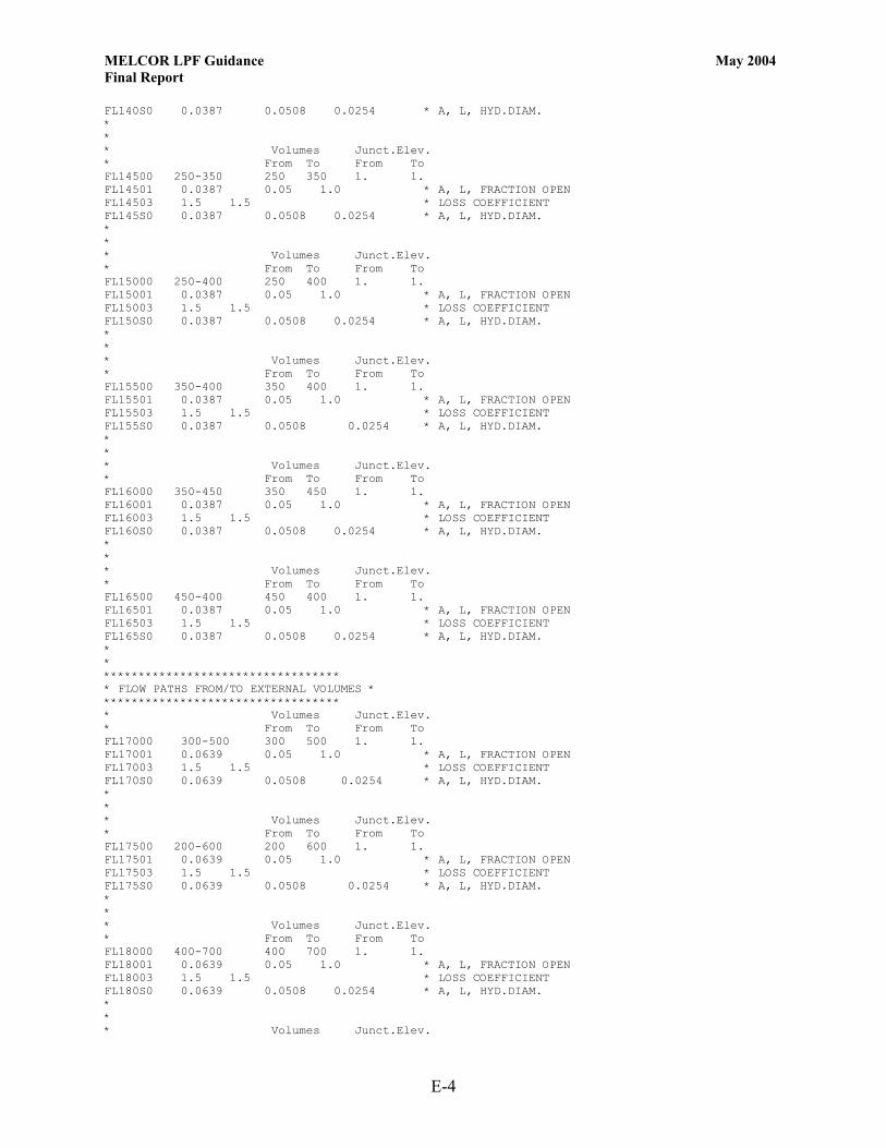
MELCOR LPF Guidance May 2004 Final Report
E-4
FL140S0 0.0387 0.0508 0.0254 * A, L, HYD.DIAM. * * * Volumes Junct.Elev. * From To From To FL14500 250-350 250 350 1. 1. FL14501 0.0387 0.05 1.0 * A, L, FRACTION OPEN FL14503 1.5 1.5 * LOSS COEFFICIENT FL145S0 0.0387 0.0508 0.0254 * A, L, HYD.DIAM. * * * Volumes Junct.Elev. * From To From To FL15000 250-400 250 400 1. 1. FL15001 0.0387 0.05 1.0 * A, L, FRACTION OPEN FL15003 1.5 1.5 * LOSS COEFFICIENT FL150S0 0.0387 0.0508 0.0254 * A, L, HYD.DIAM. * * * Volumes Junct.Elev. * From To From To FL15500 350-400 350 400 1. 1. FL15501 0.0387 0.05 1.0 * A, L, FRACTION OPEN FL15503 1.5 1.5 * LOSS COEFFICIENT FL155S0 0.0387 0.0508 0.0254 * A, L, HYD.DIAM. * * * Volumes Junct.Elev. * From To From To FL16000 350-450 350 450 1. 1. FL16001 0.0387 0.05 1.0 * A, L, FRACTION OPEN FL16003 1.5 1.5 * LOSS COEFFICIENT FL160S0 0.0387 0.0508 0.0254 * A, L, HYD.DIAM. * * * Volumes Junct.Elev. * From To From To FL16500 450-400 450 400 1. 1. FL16501 0.0387 0.05 1.0 * A, L, FRACTION OPEN FL16503 1.5 1.5 * LOSS COEFFICIENT FL165S0 0.0387 0.0508 0.0254 * A, L, HYD.DIAM. * * ********************************** * FLOW PATHS FROM/TO EXTERNAL VOLUMES * ********************************** * Volumes Junct.Elev. * From To From To FL17000 300-500 300 500 1. 1. FL17001 0.0639 0.05 1.0 * A, L, FRACTION OPEN FL17003 1.5 1.5 * LOSS COEFFICIENT FL170S0 0.0639 0.0508 0.0254 * A, L, HYD.DIAM. * * * Volumes Junct.Elev. * From To From To FL17500 200-600 200 600 1. 1. FL17501 0.0639 0.05 1.0 * A, L, FRACTION OPEN FL17503 1.5 1.5 * LOSS COEFFICIENT FL175S0 0.0639 0.0508 0.0254 * A, L, HYD.DIAM. * * * Volumes Junct.Elev. * From To From To FL18000 400-700 400 700 1. 1. FL18001 0.0639 0.05 1.0 * A, L, FRACTION OPEN FL18003 1.5 1.5 * LOSS COEFFICIENT FL180S0 0.0639 0.0508 0.0254 * A, L, HYD.DIAM. * * * Volumes Junct.Elev.

MELCOR LPF Guidance May 2004 Final Report
E-5
* From To From To FL18500 450-800 450 800 1. 1. FL18501 3.9 0.05 1.0 * A, L, FRACTION OPEN FL18503 1.5 1.5 * LOSS COEFFICIENT FL185S0 3.9 0.0508 1.6 * A, L, HYD.DIAM. FL185V0 -1 251 251 * USE A CONTROL FUNCTION CF25100 'JUN CONROL' TAB-FUN 1 1.0 * TRIP ON TIME CF25101 0.0 CF25103 233 * TAB FUNCTION NUMBER CF25110 1.0 0.0 TIME * TAB FUNCTION NEXT TF23300 'MOD DOOR' 6 1.0 0. TF23310 0.0 0.0164 TF23311 120. 0.0164 TF23312 120. 1.0 TF23313 720. 1.0 TF23314 720. 0.0164 TF23315 200000. 0.0164 * * VENTILATION SUPPLY WALL OPENING * Volumes Junct.Elev. * From To From To FL19000 700-200 700 200 1. 1. FL19001 2.0 0.05 1.0 * A, L, FRACTION OPEN FL19003 1.5 1.5 * LOSS COEFFICIENT FL190S0 2.0 0.3048 2.0 * A, L, HYD.DIAM. * * * * ************************* * HEAT STRUCTURES INPUT * ************************* * * * HS10001000 3 1 * 3 NODES, RECTANGULAR GEOMETRY HS10001001 'FLOOR 100' * STRUCTURE NAME HS10001002 0.0 0.0 * BOTTOM AT 0.0 M, HORIZONTAL HS10001100 -1 1 0.0 * DEFINE NODE POSITIONS, FIRST AT 0.0 M HS10001101 0.3048 3 * THIRD NODE NODE AT 0.3048 M HS10001200 -1 * DEFINE MATERIAL HS10001201 'CONCRETE' 2 * 2 MESH POINTS HS10001300 0 * NO INTERNAL POWER SOURCE HS10001400 0 * ADIABATIC LOWER BC HS10001600 1 100 EXT 0.0 0.0 * UPPER BC * Area Char.L Width * EXTernal heat transfer HS10001700 278.7 20.0 20.0 * SUFRACE AREA M**2 * HS10002000 3 1 HS10002001 'CEILING 100' HS10002002 4.0 0.0 * Bottom NB HS10002100 -1 1 0.0 HS10002101 0.3048 3 HS10002200 -1 HS10002201 'CONCRETE' 2 HS10002300 0 HS10002400 1 100 EXT 0.0 0.0 * Area Char.L Width HS10002500 278.7 5.0 5.0 HS10002600 0 * HS10003000 3 1 HS10003001 'WALL 100' HS10003002 0.0 1.0 * BOTTOM AT 0.0 M, VERTICAL HS10003100 -1 1 0.0 HS10003101 0.3048 3 HS10003200 -1 HS10003201 'CONCRETE' 2 HS10003300 0

MELCOR LPF Guidance May 2004 Final Report
E-6
HS10003400 1 100 EXT 0.0 0.0 * Area Char.L Width HS10003500 265.7 3.0 3.0 HS10003600 1 300 EXT 0.0 0.0 * Area Char.L Width HS10003700 265.7 3.0 3.0 * * * HS15001000 3 1 * 3 NODES, RECTANGULAR GEOMETRY HS15001001 'FLOOR 150' * STRUCTURE NAME HS15001002 0.0 0.0 * BOTTOM AT 0.0 M, HORIZONTAL HS15001100 -1 1 0.0 * DEFINE NODE POSITIONS, FIRST AT 0.0 M HS15001101 0.3048 3 * THIRD NODE NODE AT 0.3048 M HS15001200 -1 * DEFINE MATERIAL HS15001201 'CONCRETE' 2 * 2 MESH POINTS HS15001300 0 * NO INTERNAL POWER SOURCE HS15001400 0 * ADIABATIC LOWER BC HS15001600 1 150 EXT 0.0 0.0 * UPPER BC * Area Char.L Width * EXTernal heat transfer HS15001700 426.4 20.0 20.0 * SUFRACE AREA M**2 * HS15002000 3 1 HS15002001 'CEILING 150' HS15002002 4.0 0.0 * Bottom NB HS15002100 -1 1 0.0 HS15002101 0.3048 3 HS15002200 -1 HS15002201 'CONCRETE' 2 HS15002300 0 HS15002400 1 150 EXT 0.0 0.0 * Area Char.L Width HS15002500 426.4 5.0 5.0 HS15002600 0 * HS15003000 3 1 HS15003001 'WALL 150' HS15003002 0.0 1.0 * BOTTOM AT 0.0 M, VERTICAL HS15003100 -1 1 0.0 HS15003101 0.3048 3 HS15003200 -1 HS15003201 'CONCRETE' 2 HS15003300 0 HS15003400 1 150 EXT 0.0 0.0 * Area Char.L Width HS15003500 335.8 3.0 3.0 HS15003600 1 300 EXT 0.0 0.0 * Area Char.L Width HS15003700 335.8 3.0 3.0 * * * HS20001000 3 1 * 3 NODES, RECTANGULAR GEOMETRY HS20001001 'FLOOR 200' * STRUCTURE NAME HS20001002 0.0 0.0 * BOTTOM AT 0.0 M, HORIZONTAL HS20001100 -1 1 0.0 * DEFINE NODE POSITIONS, FIRST AT 0.0 M HS20001101 0.3048 3 * THIRD NODE NODE AT 0.3048 M HS20001200 -1 * DEFINE MATERIAL HS20001201 'CONCRETE' 2 * 2 MESH POINTS HS20001300 0 * NO INTERNAL POWER SOURCE HS20001400 0 * ADIABATIC LOWER BC HS20001600 1 200 EXT 0.0 0.0 * UPPER BC * Area Char.L Width * EXTernal heat transfer HS20001700 426.4 20.0 20.0 * SUFRACE AREA M**2 * HS20002000 3 1 HS20002001 'CEILING 200' HS20002002 4.0 0.0 * Bottom NB HS20002100 -1 1 0.0 HS20002101 0.3048 3 HS20002200 -1

MELCOR LPF Guidance May 2004 Final Report
E-7
HS20002201 'CONCRETE' 2 HS20002300 0 HS20002400 1 200 EXT 0.0 0.0 * Area Char.L Width HS20002500 426.4 5.0 5.0 HS20002600 0 * HS20003000 3 1 HS20003001 'WALL 200' HS20003002 0.0 1.0 * BOTTOM AT 0.0 M, VERTICAL HS20003100 -1 1 0.0 HS20003101 0.3048 3 HS20003200 -1 HS20003201 'CONCRETE' 2 HS20003300 0 HS20003400 1 200 EXT 0.0 0.0 * Area Char.L Width HS20003500 335.8 3.0 3.0 HS20003600 1 300 EXT 0.0 0.0 * Area Char.L Width HS20003700 335.8 3.0 3.0 * * * HS25001000 3 1 * 3 NODES, RECTANGULAR GEOMETRY HS25001001 'FLOOR 250' * STRUCTURE NAME HS25001002 0.0 0.0 * BOTTOM AT 0.0 M, HORIZONTAL HS25001100 -1 1 0.0 * DEFINE NODE POSITIONS, FIRST AT 0.0 M HS25001101 0.3048 3 * THIRD NODE NODE AT 0.3048 M HS25001200 -1 * DEFINE MATERIAL HS25001201 'CONCRETE' 2 * 2 MESH POINTS HS25001300 0 * NO INTERNAL POWER SOURCE HS25001400 0 * ADIABATIC LOWER BC HS25001600 1 250 EXT 0.0 0.0 * UPPER BC * Area Char.L Width * EXTernal heat transfer HS25001700 94.8 20.0 20.0 * SUFRACE AREA M**2 * HS25002000 3 1 HS25002001 'CEILING 250' HS25002002 4.0 0.0 * Bottom NB HS25002100 -1 1 0.0 HS25002101 0.3048 3 HS25002200 -1 HS25002201 'CONCRETE' 2 HS25002300 0 HS25002400 1 250 EXT 0.0 0.0 * Area Char.L Width HS25002500 94.8 5.0 5.0 HS25002600 0 * HS25003000 3 1 HS25003001 'WALL 250' HS25003002 0.0 1.0 * BOTTOM AT 0.0 M, VERTICAL HS25003100 -1 1 0.0 HS25003101 0.3048 3 HS25003200 -1 HS25003201 'CONCRETE' 2 HS25003300 0 HS25003400 1 250 EXT 0.0 0.0 * Area Char.L Width HS25003500 425.1 3.0 3.0 HS25003600 1 300 EXT 0.0 0.0 * Area Char.L Width HS25003700 425.1 3.0 3.0 * * * HS30001000 3 1 * 3 NODES, RECTANGULAR GEOMETRY HS30001001 'FLOOR 300' * STRUCTURE NAME HS30001002 0.0 0.0 * BOTTOM AT 0.0 M, HORIZONTAL HS30001100 -1 1 0.0 * DEFINE NODE POSITIONS, FIRST AT 0.0 M

MELCOR LPF Guidance May 2004 Final Report
E-8
HS30001101 0.3048 3 * THIRD NODE NODE AT 0.3048 M HS30001200 -1 * DEFINE MATERIAL HS30001201 'CONCRETE' 2 * 2 MESH POINTS HS30001300 0 * NO INTERNAL POWER SOURCE HS30001400 0 * ADIABATIC LOWER BC HS30001600 1 300 EXT 0.0 0.0 * UPPER BC * Area Char.L Width * EXTernal heat transfer HS30001700 209. 20.0 20.0 * SUFRACE AREA M**2 * HS30002000 3 1 HS30002001 'CEILING 300' HS30002002 4.0 0.0 * Bottom NB HS30002100 -1 1 0.0 HS30002101 0.3048 3 HS30002200 -1 HS30002201 'CONCRETE' 2 HS30002300 0 HS30002400 1 300 EXT 0.0 0.0 * Area Char.L Width HS30002500 209. 5.0 5.0 HS30002600 0 * HS30003000 3 1 HS30003001 'WALL 300' HS30003002 0.0 1.0 * BOTTOM AT 0.0 M, VERTICAL HS30003100 -1 1 0.0 HS30003101 0.3048 3 HS30003200 -1 HS30003201 'CONCRETE' 2 HS30003300 0 HS30003400 1 300 EXT 0.0 0.0 * Area Char.L Width HS30003500 229.5 3.0 3.0 HS30003600 1 150 EXT 0.0 0.0 * Area Char.L Width HS30003700 229.5 3.0 3.0 * * * HS35001000 3 1 * 3 NODES, RECTANGULAR GEOMETRY HS35001001 'FLOOR 350' * STRUCTURE NAME HS35001002 0.0 0.0 * BOTTOM AT 0.0 M, HORIZONTAL HS35001100 -1 1 0.0 * DEFINE NODE POSITIONS, FIRST AT 0.0 M HS35001101 0.3048 3 * THIRD NODE NODE AT 0.3048 M HS35001200 -1 * DEFINE MATERIAL HS35001201 'CONCRETE' 2 * 2 MESH POINTS HS35001300 0 * NO INTERNAL POWER SOURCE HS35001400 0 * ADIABATIC LOWER BC HS35001600 1 350 EXT 0.0 0.0 * UPPER BC * Area Char.L Width * EXTernal heat transfer HS35001700 325.2 20.0 20.0 * SUFRACE AREA M**2 * HS35002000 3 1 HS35002001 'CEILING 350' HS35002002 4.0 0.0 * Bottom NB HS35002100 -1 1 0.0 HS35002101 0.3048 3 HS35002200 -1 HS35002201 'CONCRETE' 2 HS35002300 0 HS35002400 1 350 EXT 0.0 0.0 * Area Char.L Width HS35002500 325.2 5.0 5.0 HS35002600 0 * HS35003000 3 1 HS35003001 'EAST WALL' HS35003002 0.0 1.0 * BOTTOM AT 0.0 M, VERTICAL HS35003100 -1 1 0.0 HS35003101 0.3048 3 HS35003200 -1
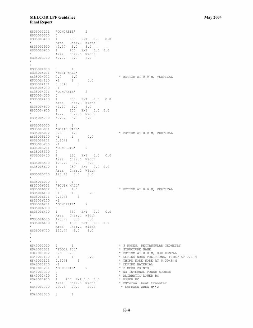
MELCOR LPF Guidance May 2004 Final Report
E-9
HS35003201 'CONCRETE' 2 HS35003300 0 HS35003400 1 350 EXT 0.0 0.0 * Area Char.L Width HS35003500 42.27 3.0 3.0 HS35003600 1 400 EXT 0.0 0.0 * Area Char.L Width HS35003700 42.27 3.0 3.0 * * HS35004000 3 1 HS35004001 'WEST WALL' HS35004002 0.0 1.0 * BOTTOM AT 0.0 M, VERTICAL HS35004100 -1 1 0.0 HS35004101 0.3048 3 HS35004200 -1 HS35004201 'CONCRETE' 2 HS35004300 0 HS35004400 1 350 EXT 0.0 0.0 * Area Char.L Width HS35004500 42.27 3.0 3.0 HS35004600 1 300 EXT 0.0 0.0 * Area Char.L Width HS35004700 42.27 3.0 3.0 * HS35005000 3 1 HS35005001 'NORTH WALL' HS35005002 0.0 1.0 * BOTTOM AT 0.0 M, VERTICAL HS35005100 -1 1 0.0 HS35005101 0.3048 3 HS35005200 -1 HS35005201 'CONCRETE' 2 HS35005300 0 HS35005400 1 350 EXT 0.0 0.0 * Area Char.L Width HS35005500 120.77 3.0 3.0 HS35005600 1 250 EXT 0.0 0.0 * Area Char.L Width HS35005700 120.77 3.0 3.0 * HS35006000 3 1 HS35006001 'SOUTH WALL' HS35006002 0.0 1.0 * BOTTOM AT 0.0 M, VERTICAL HS35006100 -1 1 0.0 HS35006101 0.3048 3 HS35006200 -1 HS35006201 'CONCRETE' 2 HS35006300 0 HS35006400 1 350 EXT 0.0 0.0 * Area Char.L Width HS35006500 120.77 3.0 3.0 HS35006600 1 450 EXT 0.0 0.0 * Area Char.L Width HS35006700 120.77 3.0 3.0 * * * HS40001000 3 1 * 3 NODES, RECTANGULAR GEOMETRY HS40001001 'FLOOR 400' * STRUCTURE NAME HS40001002 0.0 0.0 * BOTTOM AT 0.0 M, HORIZONTAL HS40001100 -1 1 0.0 * DEFINE NODE POSITIONS, FIRST AT 0.0 M HS40001101 0.3048 3 * THIRD NODE NODE AT 0.3048 M HS40001200 -1 * DEFINE MATERIAL HS40001201 'CONCRETE' 2 * 2 MESH POINTS HS40001300 0 * NO INTERNAL POWER SOURCE HS40001400 0 * ADIABATIC LOWER BC HS40001600 1 400 EXT 0.0 0.0 * UPPER BC * Area Char.L Width * EXTernal heat transfer HS40001700 292.6 20.0 20.0 * SUFRACE AREA M**2 * HS40002000 3 1
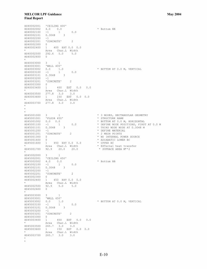
MELCOR LPF Guidance May 2004 Final Report
E-10
HS40002001 'CEILING 400' HS40002002 4.0 0.0 * Bottom NB HS40002100 -1 1 0.0 HS40002101 0.3048 3 HS40002200 -1 HS40002201 'CONCRETE' 2 HS40002300 0 HS40002400 1 400 EXT 0.0 0.0 * Area Char.L Width HS40002500 292.6 5.0 5.0 HS40002600 0 * HS40003000 3 1 HS40003001 'WALL 400' HS40003002 0.0 1.0 * BOTTOM AT 0.0 M, VERTICAL HS40003100 -1 1 0.0 HS40003101 0.3048 3 HS40003200 -1 HS40003201 'CONCRETE' 2 HS40003300 0 HS40003400 1 400 EXT 0.0 0.0 * Area Char.L Width HS40003500 277.8 3.0 3.0 HS40003600 1 150 EXT 0.0 0.0 * Area Char.L Width HS40003700 277.8 3.0 3.0 * * * HS45001000 3 1 * 3 NODES, RECTANGULAR GEOMETRY HS45001001 'FLOOR 450' * STRUCTURE NAME HS45001002 0.0 0.0 * BOTTOM AT 0.0 M, HORIZONTAL HS45001100 -1 1 0.0 * DEFINE NODE POSITIONS, FIRST AT 0.0 M HS45001101 0.3048 3 * THIRD NODE NODE AT 0.3048 M HS45001200 -1 * DEFINE MATERIAL HS45001201 'CONCRETE' 2 * 2 MESH POINTS HS45001300 0 * NO INTERNAL POWER SOURCE HS45001400 0 * ADIABATIC LOWER BC HS45001600 1 450 EXT 0.0 0.0 * UPPER BC * Area Char.L Width * EXTernal heat transfer HS45001700 92.9 20.0 20.0 * SUFRACE AREA M**2 * HS45002000 3 1 HS45002001 'CEILING 450' HS45002002 4.0 0.0 * Bottom NB HS45002100 -1 1 0.0 HS45002101 0.3048 3 HS45002200 -1 HS45002201 'CONCRETE' 2 HS45002300 0 HS45002400 1 450 EXT 0.0 0.0 * Area Char.L Width HS45002500 92.9 5.0 5.0 HS45002600 0 * HS45003000 3 1 HS45003001 'WALL 450' HS45003002 0.0 1.0 * BOTTOM AT 0.0 M, VERTICAL HS45003100 -1 1 0.0 HS45003101 0.3048 3 HS45003200 -1 HS45003201 'CONCRETE' 2 HS45003300 0 HS45003400 1 450 EXT 0.0 0.0 * Area Char.L Width HS45003500 265.7 3.0 3.0 HS45003600 1 150 EXT 0.0 0.0 * Area Char.L Width HS45003700 265.7 3.0 3.0 * *

MELCOR LPF Guidance May 2004 Final Report
E-11
* HS50001000 3 1 HS50001001 'FLOOR 500' HS50001002 0.0 0.0 HS50001100 -1 1 0.0 HS50001101 0.3 3 HS50001200 -1 HS50001201 'CONCRETE' 2 HS50001300 0 HS50001400 0 HS50001600 1 500 EXT 0.0 0.0 HS50001700 0.0001 0.0001 0.0001 * AREA * * * HS60001000 3 1 HS60001001 'FLOOR 600' HS60001002 0.0 0.0 HS60001100 -1 1 0.0 HS60001101 0.3 3 HS60001200 -1 HS60001201 'CONCRETE' 2 HS60001300 0 HS60001400 0 HS60001600 1 600 EXT 0.0 0.0 HS60001700 0.0001 0.0001 0.0001 * AREA * * * HS70001000 3 1 HS70001001 'FLOOR 700' HS70001002 0.0 0.0 HS70001100 -1 1 0.0 HS70001101 0.3 3 HS70001200 -1 HS70001201 'CONCRETE' 2 HS70001300 0 HS70001400 0 HS70001600 1 700 EXT 0.0 0.0 HS70001700 0.0001 0.0001 0.0001 * AREA * * * HS80001000 3 1 HS80001001 'FLOOR 800' HS80001002 0.0 0.0 HS80001100 -1 1 0.0 HS80001101 0.3 3 HS80001200 -1 HS80001201 'CONCRETE' 2 HS80001300 0 HS80001400 0 HS80001600 1 800 EXT 0.0 0.0 HS80001700 0.0001 0.0001 0.0001 * AREA * * AEROSOL SECTION RN1000 0 * ACTIVATE RNCA100 0 * NOT ACTIVE RN1001 20 2 17 0 0 1 0 RN1100 1.0e-8 3.0e-6 11.46E+3 RNACOEF 1 RNAS000 350 2 1 1. 1.0 601 2 RNAS001 2.3e-6 2. * DEFINE TABULAR FUNCTION AEROSOL RELEASE RATE * TF60100 'AEROSOL' 5 1.0 TF60110 0.0 0.000 * TIME KG RELEASE TF60111 500.0 0.000

MELCOR LPF Guidance May 2004 Final Report
E-12
TF60112 501.0 1.0 TF60113 502.0 0.0 TF60114 200000. 0.0 . *eor* melcor * ********************************** * MELCOR INPUT * ********************************** * TITLE 'TEST PROBLEM' * RESTART 0 * RESTART FROM CYCLE 0 * TEND 36000.0 * END TIME S * CPULIM 36000.0 CPULEFT 20.0 * CRTOUT * 80-COLUMN OUTPUT FORMAT * ********* * FILES * ********* * RESTARTFILE SAMPLE.RST OUTPUTFILE SAMPLE.OUT PLOTFILE SAMPLE.PTF DIAGFILE SAMPLE.DIA MESSAGEFILE SAMPLE.MES * ****************************** * TIME STEP AND EDIT CONTROL * ****************************** * TIME DTMAX DTMIN DTEDT DTPLT DTRST TIME1 0.0 0.1 0.000000001 5.0 100.0 10.0 TIME2 1200.0 10.0 0.000000001 500.0 100.0 1000.0 TIME3 1300.0 30.0 0.000000001 500.0 100.0 1000.0 TIME4 1400.0 100.0 0.000000001 1000.0 200.0 5000.0 TIME5 2500.0 200.0 0.000000001 1000.0 200.0 5000.0 .

MELCOR LPF Guidance May 2004 Final Report
F-1
Appendix F. Fire Plus Seismic (Ventilation Operating) Input File *eor* melgen * ********************************** ********** MELGEN INPUT ********** ********************************** * TITLE 'TEST PROBLEM' * DTTIME 0.001 * Initial time-step of 1 ms * CRTOUT * 80-column output format * ********* * FILES * ********* * DEFINITION OF OUTPUT FILE NAMES * OUTPUTFILE SAMPLEG.OUT DIAGFILE SAMPLEG.DIA RESTARTFILE SAMPLE.RST * * * DEFINITION OF DEFAULT FLUID * AIR DEFINITION NCG001 N2 4 * N2 IS MATERIAL NO. 4 NCG002 O2 5 * O2 IS MATERIAL NO. 5 * END AIR DEFINITION ************************** * PRIMARY SYSTEM VOLUMES * ************************** * CV10000 ROOM100 2 1 1 * ROOM-100 * VOLUME ENV. CONDITIONS CV100A1 PVOL 101352.9 * INITIAL PRESSURE CV100A4 MLFR.4 .8 MLFR.5 .2 TATM 294.3 RHUM 0.0 * 80% N2, 20% O2 * ALTITUDE OF CELL AND VOLUME CV100B1 0.0 0.0 * BOTTOM 0.0 CV100B2 4. 1104.4 * TOTAL VOLUME * * CV15000 ROOM150 2 1 1 * ROOM-150 * VOLUME ENV. CONDITIONS CV150A1 PVOL 101352.9 * INITIAL PRESSURE CV150A4 MLFR.4 .8 MLFR.5 .2 TATM 294.3 RHUM 0.0 * 80% N2, 20% O2 * ALTITUDE OF CELL AND VOLUME CV150B1 0.0 0.0 * BOTTOM AT 0.0 CV150B2 4. 1689.7 * TOTAL VOLUME * * CV20000 ROOM200 2 1 1 * ROOM-200 CV200A1 PVOL 101352.9 * INITIAL PRESSURE CV200A4 MLFR.4 .8 MLFR.5 .2 TATM 294.3 RHUM 0.0 * 80% N2, 20% O2 * ALTITUDE OF CELL AND VOLUME CV200B1 0.0 0.0 * BOTTOM AT 0.0 CV200B2 4.0 1689.7 * TOTAL VOLUME * * CV25000 ROOM250 2 1 1 * ROOM-250 CV250A1 PVOL 101352.9 * INITIAL PRESSURE CV250A4 MLFR.4 .8 MLFR.5 .2 TATM 294.3 RHUM 0.0 * 80% N2, 20% O2 * ALTITUDE OF CELL AND VOLUME CV250B1 0.0 0.0 * BOTTOM AT 0.0 CV250B2 4.0 375.5 * TOTAL VOLUME * * CV30000 ROOM300 2 1 1 * ROOM-300 CV300A1 PVOL 101352.9 * INITIAL PRESSURE

MELCOR LPF Guidance May 2004 Final Report
F-2
CV300A4 MLFR.4 .8 MLFR.5 .2 TATM 294.3 RHUM 0.0 * 80% N2, 20% O2 * ALTITUDE OF CELL AND VOLUME CV300B1 0.0 0.0 * BOTTOM AT 0.0 CV300B2 4.0 828.3 * TOTAL VOLUME * * CV35000 ROOM350 2 1 1 * ROOM-350 CV350A1 PVOL 101352.9 * INITIAL PRESSURE CV350A4 MLFR.4 .8 MLFR.5 .2 TATM 294.3 RHUM 0.0 * 80% N2, 20% O2 * ALTITUDE OF CELL AND VOLUME CV350B1 0.0 0.0 * BOTTOM AT 0.0 CV350B2 4.0 1288.4 * TOTAL VOLUME CV350C1 MASS.3 RATE CF.998 * VAPOR MASS C-FUNCTION CV350C2 ENERGY.A RATE CF.999 * CORRESPONDING ENTALPY CF99800 'VAPOR MASS' TAB-FUN 1 1.0 CF99803 998 * TF NUMBER CF99810 1.0 0.0 TIME * ARGUMENT IS TIME TF99800 'VAPOR MASS' 5 1.0 TF99810 0.0 0.0 TF99811 300. 0.001 TF99812 900. 0.001 TF99813 1200. 0.0 TF99814 200000. 0.0 * CF99900 'ENTHALPY' MULTIPLY 2 1.0 * ENTHALPY RATE CF99910 1.0 0.0 CFVALU.998 CF99911 0.0 1.0E+9 TIME * * END FIRE SOURCE * * CV40000 ROOM400 2 1 1 * ROOM-400 CV400A1 PVOL 101352.9 * INITIAL PRESSURE CV400A4 MLFR.4 .8 MLFR.5 .2 TATM 294.3 RHUM 0.0 * 80% N2, 20% O2 * ALTITUDE OF CELL AND VOLUME CV400B1 0.0 0.0 * BOTTOM AT 0.0 CV400B2 4.0 1159.6 * TOTAL VOLUME * * CV45000 ROOM450 2 1 1 * ROOM-400 CV450A1 PVOL 101352.9 * INITIAL PRESSURE CV450A4 MLFR.4 .8 MLFR.5 .2 TATM 294.3 RHUM 0.0 * 80% N2, 20% O2 * ALTITUDE OF CELL AND VOLUME CV450B1 0.0 0.0 * BOTTOM AT 0.0 CV450B2 4.0 368.1 * TOTAL VOLUME * * **************************************** * ENVIRONMENTAL VOLUME - OUTSIDE CELLS * **************************************** * CV50000 WEST-VOL500 2 1 1 * ENV-500 WEST CV500A1 PVOL 101351.6992 * INITIAL PRESSURE CV500A4 MLFR.4 .8 MLFR.5 .2 TATM 294.3 RHUM 0.0 * 80% N2, 20% O2 * ALTITUDE OF CELL AND VOLUME CV500B1 0.0 0.0 * BOTTOM AT 0.0 CV500B2 4.0 1.0E10 * TOTAL VOLUME * * CV60000 NORTH-VOL600 2 1 1 * ENV-600 NORTH CV600A1 PVOL 101351.8493 * INITIAL PRESSURE CV600A4 MLFR.4 .8 MLFR.5 .2 TATM 294.3 RHUM 0.0 * 80% N2, 20% O2 * ALTITUDE OF CELL AND VOLUME CV600B1 0.0 0.0 * BOTTOM AT 0.0 CV600B2 4.0 1.0E10 * TOTAL VOLUME * * * WIND FROM EAST AT 5 MPH CV70000 EAST-VOL700 2 1 1 * ENV-700 EAST CV700A1 PVOL 101355.0013 * INITIAL PRESSURE

MELCOR LPF Guidance May 2004 Final Report
F-3
CV700A4 MLFR.4 .8 MLFR.5 .2 TATM 294.3 RHUM 0.0 * 80% N2, 20% O2 * ALTITUDE OF CELL AND VOLUME CV700B1 0.0 0.0 * BOTTOM AT 0.0 CV700B2 4.0 1.0E10 * TOTAL VOLUME * * CV80000 SOUTH-VOL800 2 1 1 * ENV-800 SOUTH CV800A1 PVOL 101351.8493 * INITIAL PRESSURE CV800A4 MLFR.4 .8 MLFR.5 .2 TATM 294.3 RHUM 0.0 * 80% N2, 20% O2 * ALTITUDE OF CELL AND VOLUME CV800B1 0.0 0.0 * BOTTOM AT 0.0 CV800B2 4.0 1.0E10 * TOTAL VOLUME * * * FILTER SYSTEM VOLUME CV90000 FILTER-VOL900 2 1 1 * FILTER VOLUME CV900A1 PVOL 101352.9 * INITIAL PRESSURE CV900A4 MLFR.4 .8 MLFR.5 .2 TATM 294.3 RHUM 0.0 * 80% N2, 20% O2 * ALTITUDE OF CELL AND VOLUME CV900B1 0.0 0.0 * BOTTOM AT 0.0 CV900B2 4.0 1.0E10 * TOTAL VOLUME * *********************** * INTERNAL FLOW PATHS * *********************** * Volumes Junct.Elev. * From To From To FL11000 100-300 100 300 1. 1. FL11001 0.0387 0.05 1.0 * A, L, FRACTION OPEN FL11003 1.5 1.5 * LOSS COEFFICIENT FL110S0 0.0387 0.0508 0.0254 * A, L, HYD.DIAM. * * * Volumes Junct.Elev. * From To From To FL11500 100-250 100 250 1. 1. FL11501 0.0387 0.05 1.0 * A, L, FRACTION OPEN FL11503 1.5 1.5 * LOSS COEFFICIENT FL115S0 0.0387 0.0508 0.0254 * A, L, HYD.DIAM. * * * Volumes Junct.Elev. * From To From To FL12000 150-100 150 100 1. 1. FL12001 0.0387 0.05 1.0 * A, L, FRACTION OPEN FL12003 1.5 1.5 * LOSS COEFFICIENT FL120S0 0.0387 0.0508 0.0254 * A, L, HYD.DIAM. * * * Volumes Junct.Elev. * From To From To FL12500 300-350 300 350 1. 1. FL12501 0.0387 0.05 1.0 * A, L, FRACTION OPEN FL12503 1.5 1.5 * LOSS COEFFICIENT FL125S0 0.0387 0.0508 0.0254 * A, L, HYD.DIAM. * * * Volumes Junct.Elev. * From To From To FL13000 150-250 150 250 1. 1. FL13001 0.0387 0.05 1.0 * A, L, FRACTION OPEN FL13003 1.5 1.5 * LOSS COEFFICIENT FL130S0 0.0387 0.0508 0.0254 * A, L, HYD.DIAM. * * * Volumes Junct.Elev. * From To From To FL13500 150-200 150 200 1. 1. FL13501 0.0387 0.05 1.0 * A, L, FRACTION OPEN FL13503 1.5 1.5 * LOSS COEFFICIENT FL135S0 0.0387 0.0508 0.0254 * A, L, HYD.DIAM.

MELCOR LPF Guidance May 2004 Final Report
F-4
* * * Volumes Junct.Elev. * From To From To FL14000 200-250 200 250 1. 1. FL14001 0.0387 0.05 1.0 * A, L, FRACTION OPEN FL14003 1.5 1.5 * LOSS COEFFICIENT FL140S0 0.0387 0.0508 0.0254 * A, L, HYD.DIAM. * * * Volumes Junct.Elev. * From To From To FL14500 250-350 250 350 1. 1. FL14501 0.0387 0.05 1.0 * A, L, FRACTION OPEN FL14503 1.5 1.5 * LOSS COEFFICIENT FL145S0 0.0387 0.0508 0.0254 * A, L, HYD.DIAM. * * * Volumes Junct.Elev. * From To From To FL15000 250-400 250 400 1. 1. FL15001 0.0387 0.05 1.0 * A, L, FRACTION OPEN FL15003 1.5 1.5 * LOSS COEFFICIENT FL150S0 0.0387 0.0508 0.0254 * A, L, HYD.DIAM. * * * Volumes Junct.Elev. * From To From To FL15500 350-400 350 400 1. 1. FL15501 0.0387 0.05 1.0 * A, L, FRACTION OPEN FL15503 1.5 1.5 * LOSS COEFFICIENT FL155S0 0.0387 0.0508 0.0254 * A, L, HYD.DIAM. * * * Volumes Junct.Elev. * From To From To FL16000 350-450 350 450 1. 1. FL16001 0.0387 0.05 1.0 * A, L, FRACTION OPEN FL16003 1.5 1.5 * LOSS COEFFICIENT FL160S0 0.0387 0.0508 0.0254 * A, L, HYD.DIAM. * * * Volumes Junct.Elev. * From To From To FL16500 450-400 450 400 1. 1. FL16501 0.0387 0.05 1.0 * A, L, FRACTION OPEN FL16503 1.5 1.5 * LOSS COEFFICIENT FL165S0 0.0387 0.0508 0.0254 * A, L, HYD.DIAM. * * ********************************** * FLOW PATHS FROM/TO EXTERNAL VOLUMES * ********************************** * Volumes Junct.Elev. * From To From To FL17000 300-500 300 500 1. 1. FL17001 0.0639 0.05 1.0 * A, L, FRACTION OPEN FL17003 1.5 1.5 * LOSS COEFFICIENT FL170S0 0.0639 0.0508 0.0254 * A, L, HYD.DIAM. * * * Volumes Junct.Elev. * From To From To FL17500 200-600 200 600 1. 1. FL17501 0.0639 0.05 1.0 * A, L, FRACTION OPEN FL17503 1.5 1.5 * LOSS COEFFICIENT FL175S0 0.0639 0.0508 0.0254 * A, L, HYD.DIAM. * * * Volumes Junct.Elev. * From To From To

MELCOR LPF Guidance May 2004 Final Report
F-5
FL18000 400-700 400 700 1. 1. FL18001 0.0639 0.05 1.0 * A, L, FRACTION OPEN FL18003 1.5 1.5 * LOSS COEFFICIENT FL180S0 0.0639 0.0508 0.0254 * A, L, HYD.DIAM. * * * Volumes Junct.Elev. * From To From To FL18500 450-800 450 800 1. 1. FL18501 3.9 0.05 1.0 * A, L, FRACTION OPEN FL18503 1.5 1.5 * LOSS COEFFICIENT FL185S0 3.9 0.0508 1.6 * A, L, HYD.DIAM. FL185V0 -1 251 251 * USE A CONTROL FUNCTION CF25100 'JUN CONROL' TAB-FUN 1 1.0 * TRIP ON TIME CF25101 0.0 CF25103 233 * TAB FUNCTION NUMBER CF25110 1.0 0.0 TIME * TAB FUNCTION NEXT TF23300 'MOD DOOR' 6 1.0 0. TF23310 0.0 0.0164 TF23311 120. 0.0164 TF23312 120. 1.0 TF23313 720. 1.0 TF23314 720. 0.0164 TF23315 200000. 0.0164 * * VENTILATION SUPPLY WALL OPENING * Volumes Junct.Elev. * From To From To FL19000 700-200 700 200 1. 1. FL19001 2.0 0.05 1.0 * A, L, FRACTION OPEN FL19003 1.5 1.5 * LOSS COEFFICIENT FL190S0 2.0 0.3048 2.0 * A, L, HYD.DIAM. * * ******************** * TO FILTER SYSTEM * ******************** * * FIXED FLOW CONDITION TO FILTER SYSTEM * Volumes Junct.Elev. * From To From To FL20100 100-900 100 900 1. 1. FL20101 1.0 0.05 1.0 * A, L, FRACTION OPEN FL201S0 1.0 0.3048 1.0 * A, L, HYD.DIAM. FL201T0 1 201 TF20100 'FIXED FLOW' 3 1.0 0.0 TF20110 0. 1.839 TF20111 10. 1.839 TF20112 500000. 1.839 * * * Volumes Junct.Elev. * From To From To FL20200 150-900 150 900 1. 1. FL20201 1.0 0.05 1.0 * A, L, FRACTION OPEN FL202S0 1.0 0.3048 1.0 * A, L, HYD.DIAM. FL202T0 1 202 TF20200 'FIXED FLOW' 3 1.0 0.0 TF20210 0. 2.813 TF20211 10. 2.813 TF20212 500000. 2.813 * * * Volumes Junct.Elev. * From To From To FL20300 200-900 200 900 1. 1. FL20301 1.0 0.05 1.0 * A, L, FRACTION OPEN FL203S0 1.0 0.3048 1.0 * A, L, HYD.DIAM. FL203T0 1 203

MELCOR LPF Guidance May 2004 Final Report
F-6
TF20300 'FIXED FLOW' 3 1.0 0.0 TF20310 0. 2.813 TF20311 10. 2.813 TF20312 500000. 2.813 * * * Volumes Junct.Elev. * From To From To FL20400 250-900 250 900 1. 1. FL20401 1.0 0.05 1.0 * A, L, FRACTION OPEN FL204S0 1.0 0.3048 1.0 * A, L, HYD.DIAM. FL204T0 1 204 TF20400 'FIXED FLOW' 3 1.0 0.0 TF20410 0. 0.625 TF20411 10. 0.625 TF20412 500000. 0.625 * * * Volumes Junct.Elev. * From To From To FL20500 300-900 300 900 1. 1. FL20501 1.0 0.05 1.0 * A, L, FRACTION OPEN FL205S0 1.0 0.3048 1.0 * A, L, HYD.DIAM. FL205T0 1 205 TF20500 'FIXED FLOW' 3 1.0 0.0 TF20510 0. 1.379 TF20511 10. 1.379 TF20512 500000. 1.379 * * * Volumes Junct.Elev. * From To From To FL20600 350-900 350 900 1. 1. FL20601 1.0 0.05 1.0 * A, L, FRACTION OPEN FL206S0 1.0 0.3048 1.0 * A, L, HYD.DIAM. FL206T0 1 206 TF20600 'FIXED FLOW' 3 1.0 0.0 TF20610 0. 2.145 TF20611 10. 2.145 TF20612 500000. 2.145 * * * Volumes Junct.Elev. * From To From To FL20700 400-900 400 900 1. 1. FL20701 1.0 0.05 1.0 * A, L, FRACTION OPEN FL207S0 1.0 0.3048 1.0 * A, L, HYD.DIAM. FL207T0 1 207 TF20700 'FIXED FLOW' 3 1.0 0.0 TF20710 0. 1.931 TF20711 10. 1.931 TF20712 500000. 1.931 * * * Volumes Junct.Elev. * From To From To FL20800 450-900 450 900 1. 1. FL20801 1.0 0.05 1.0 * A, L, FRACTION OPEN FL208S0 1.0 0.3048 1.0 * A, L, HYD.DIAM. FL208T0 1 208 TF20800 'FIXED FLOW' 3 1.0 0.0 TF20810 0. 0.613 TF20811 10. 0.613 TF20812 500000. 0.613 * * ************************* * HEAT STRUCTURES INPUT * ************************* * *

MELCOR LPF Guidance May 2004 Final Report
F-7
* HS10001000 3 1 * 3 NODES, RECTANGULAR GEOMETRY HS10001001 'FLOOR 100' * STRUCTURE NAME HS10001002 0.0 0.0 * BOTTOM AT 0.0 M, HORIZONTAL HS10001100 -1 1 0.0 * DEFINE NODE POSITIONS, FIRST AT 0.0 M HS10001101 0.3048 3 * THIRD NODE NODE AT 0.3048 M HS10001200 -1 * DEFINE MATERIAL HS10001201 'CONCRETE' 2 * 2 MESH POINTS HS10001300 0 * NO INTERNAL POWER SOURCE HS10001400 0 * ADIABATIC LOWER BC HS10001600 1 100 EXT 0.0 0.0 * UPPER BC * Area Char.L Width * EXTernal heat transfer HS10001700 278.7 20.0 20.0 * SUFRACE AREA M**2 * HS10002000 3 1 HS10002001 'CEILING 100' HS10002002 4.0 0.0 * Bottom NB HS10002100 -1 1 0.0 HS10002101 0.3048 3 HS10002200 -1 HS10002201 'CONCRETE' 2 HS10002300 0 HS10002400 1 100 EXT 0.0 0.0 * Area Char.L Width HS10002500 278.7 5.0 5.0 HS10002600 0 * HS10003000 3 1 HS10003001 'WALL 100' HS10003002 0.0 1.0 * BOTTOM AT 0.0 M, VERTICAL HS10003100 -1 1 0.0 HS10003101 0.3048 3 HS10003200 -1 HS10003201 'CONCRETE' 2 HS10003300 0 HS10003400 1 100 EXT 0.0 0.0 * Area Char.L Width HS10003500 265.7 3.0 3.0 HS10003600 1 300 EXT 0.0 0.0 * Area Char.L Width HS10003700 265.7 3.0 3.0 * * * HS15001000 3 1 * 3 NODES, RECTANGULAR GEOMETRY HS15001001 'FLOOR 150' * STRUCTURE NAME HS15001002 0.0 0.0 * BOTTOM AT 0.0 M, HORIZONTAL HS15001100 -1 1 0.0 * DEFINE NODE POSITIONS, FIRST AT 0.0 M HS15001101 0.3048 3 * THIRD NODE NODE AT 0.3048 M HS15001200 -1 * DEFINE MATERIAL HS15001201 'CONCRETE' 2 * 2 MESH POINTS HS15001300 0 * NO INTERNAL POWER SOURCE HS15001400 0 * ADIABATIC LOWER BC HS15001600 1 150 EXT 0.0 0.0 * UPPER BC * Area Char.L Width * EXTernal heat transfer HS15001700 426.4 20.0 20.0 * SUFRACE AREA M**2 * HS15002000 3 1 HS15002001 'CEILING 150' HS15002002 4.0 0.0 * Bottom NB HS15002100 -1 1 0.0 HS15002101 0.3048 3 HS15002200 -1 HS15002201 'CONCRETE' 2 HS15002300 0 HS15002400 1 150 EXT 0.0 0.0 * Area Char.L Width HS15002500 426.4 5.0 5.0 HS15002600 0 * HS15003000 3 1

MELCOR LPF Guidance May 2004 Final Report
F-8
HS15003001 'WALL 150' HS15003002 0.0 1.0 * BOTTOM AT 0.0 M, VERTICAL HS15003100 -1 1 0.0 HS15003101 0.3048 3 HS15003200 -1 HS15003201 'CONCRETE' 2 HS15003300 0 HS15003400 1 150 EXT 0.0 0.0 * Area Char.L Width HS15003500 335.8 3.0 3.0 HS15003600 1 300 EXT 0.0 0.0 * Area Char.L Width HS15003700 335.8 3.0 3.0 * * * HS20001000 3 1 * 3 NODES, RECTANGULAR GEOMETRY HS20001001 'FLOOR 200' * STRUCTURE NAME HS20001002 0.0 0.0 * BOTTOM AT 0.0 M, HORIZONTAL HS20001100 -1 1 0.0 * DEFINE NODE POSITIONS, FIRST AT 0.0 M HS20001101 0.3048 3 * THIRD NODE NODE AT 0.3048 M HS20001200 -1 * DEFINE MATERIAL HS20001201 'CONCRETE' 2 * 2 MESH POINTS HS20001300 0 * NO INTERNAL POWER SOURCE HS20001400 0 * ADIABATIC LOWER BC HS20001600 1 200 EXT 0.0 0.0 * UPPER BC * Area Char.L Width * EXTernal heat transfer HS20001700 426.4 20.0 20.0 * SUFRACE AREA M**2 * HS20002000 3 1 HS20002001 'CEILING 200' HS20002002 4.0 0.0 * Bottom NB HS20002100 -1 1 0.0 HS20002101 0.3048 3 HS20002200 -1 HS20002201 'CONCRETE' 2 HS20002300 0 HS20002400 1 200 EXT 0.0 0.0 * Area Char.L Width HS20002500 426.4 5.0 5.0 HS20002600 0 * HS20003000 3 1 HS20003001 'WALL 200' HS20003002 0.0 1.0 * BOTTOM AT 0.0 M, VERTICAL HS20003100 -1 1 0.0 HS20003101 0.3048 3 HS20003200 -1 HS20003201 'CONCRETE' 2 HS20003300 0 HS20003400 1 200 EXT 0.0 0.0 * Area Char.L Width HS20003500 335.8 3.0 3.0 HS20003600 1 300 EXT 0.0 0.0 * Area Char.L Width HS20003700 335.8 3.0 3.0 * * * HS25001000 3 1 * 3 NODES, RECTANGULAR GEOMETRY HS25001001 'FLOOR 250' * STRUCTURE NAME HS25001002 0.0 0.0 * BOTTOM AT 0.0 M, HORIZONTAL HS25001100 -1 1 0.0 * DEFINE NODE POSITIONS, FIRST AT 0.0 M HS25001101 0.3048 3 * THIRD NODE NODE AT 0.3048 M HS25001200 -1 * DEFINE MATERIAL HS25001201 'CONCRETE' 2 * 2 MESH POINTS HS25001300 0 * NO INTERNAL POWER SOURCE HS25001400 0 * ADIABATIC LOWER BC HS25001600 1 250 EXT 0.0 0.0 * UPPER BC * Area Char.L Width * EXTernal heat transfer HS25001700 94.8 20.0 20.0 * SUFRACE AREA M**2

MELCOR LPF Guidance May 2004 Final Report
F-9
* HS25002000 3 1 HS25002001 'CEILING 250' HS25002002 4.0 0.0 * Bottom NB HS25002100 -1 1 0.0 HS25002101 0.3048 3 HS25002200 -1 HS25002201 'CONCRETE' 2 HS25002300 0 HS25002400 1 250 EXT 0.0 0.0 * Area Char.L Width HS25002500 94.8 5.0 5.0 HS25002600 0 * HS25003000 3 1 HS25003001 'WALL 250' HS25003002 0.0 1.0 * BOTTOM AT 0.0 M, VERTICAL HS25003100 -1 1 0.0 HS25003101 0.3048 3 HS25003200 -1 HS25003201 'CONCRETE' 2 HS25003300 0 HS25003400 1 250 EXT 0.0 0.0 * Area Char.L Width HS25003500 425.1 3.0 3.0 HS25003600 1 300 EXT 0.0 0.0 * Area Char.L Width HS25003700 425.1 3.0 3.0 * * * HS30001000 3 1 * 3 NODES, RECTANGULAR GEOMETRY HS30001001 'FLOOR 300' * STRUCTURE NAME HS30001002 0.0 0.0 * BOTTOM AT 0.0 M, HORIZONTAL HS30001100 -1 1 0.0 * DEFINE NODE POSITIONS, FIRST AT 0.0 M HS30001101 0.3048 3 * THIRD NODE NODE AT 0.3048 M HS30001200 -1 * DEFINE MATERIAL HS30001201 'CONCRETE' 2 * 2 MESH POINTS HS30001300 0 * NO INTERNAL POWER SOURCE HS30001400 0 * ADIABATIC LOWER BC HS30001600 1 300 EXT 0.0 0.0 * UPPER BC * Area Char.L Width * EXTernal heat transfer HS30001700 209. 20.0 20.0 * SUFRACE AREA M**2 * HS30002000 3 1 HS30002001 'CEILING 300' HS30002002 4.0 0.0 * Bottom NB HS30002100 -1 1 0.0 HS30002101 0.3048 3 HS30002200 -1 HS30002201 'CONCRETE' 2 HS30002300 0 HS30002400 1 300 EXT 0.0 0.0 * Area Char.L Width HS30002500 209. 5.0 5.0 HS30002600 0 * HS30003000 3 1 HS30003001 'WALL 300' HS30003002 0.0 1.0 * BOTTOM AT 0.0 M, VERTICAL HS30003100 -1 1 0.0 HS30003101 0.3048 3 HS30003200 -1 HS30003201 'CONCRETE' 2 HS30003300 0 HS30003400 1 300 EXT 0.0 0.0 * Area Char.L Width HS30003500 229.5 3.0 3.0 HS30003600 1 150 EXT 0.0 0.0 * Area Char.L Width HS30003700 229.5 3.0 3.0

MELCOR LPF Guidance May 2004 Final Report
F-10
* * * HS35001000 3 1 * 3 NODES, RECTANGULAR GEOMETRY HS35001001 'FLOOR 350' * STRUCTURE NAME HS35001002 0.0 0.0 * BOTTOM AT 0.0 M, HORIZONTAL HS35001100 -1 1 0.0 * DEFINE NODE POSITIONS, FIRST AT 0.0 M HS35001101 0.3048 3 * THIRD NODE NODE AT 0.3048 M HS35001200 -1 * DEFINE MATERIAL HS35001201 'CONCRETE' 2 * 2 MESH POINTS HS35001300 0 * NO INTERNAL POWER SOURCE HS35001400 0 * ADIABATIC LOWER BC HS35001600 1 350 EXT 0.0 0.0 * UPPER BC * Area Char.L Width * EXTernal heat transfer HS35001700 325.2 20.0 20.0 * SUFRACE AREA M**2 * HS35002000 3 1 HS35002001 'CEILING 350' HS35002002 4.0 0.0 * Bottom NB HS35002100 -1 1 0.0 HS35002101 0.3048 3 HS35002200 -1 HS35002201 'CONCRETE' 2 HS35002300 0 HS35002400 1 350 EXT 0.0 0.0 * Area Char.L Width HS35002500 325.2 5.0 5.0 HS35002600 0 * HS35003000 3 1 HS35003001 'EAST WALL' HS35003002 0.0 1.0 * BOTTOM AT 0.0 M, VERTICAL HS35003100 -1 1 0.0 HS35003101 0.3048 3 HS35003200 -1 HS35003201 'CONCRETE' 2 HS35003300 0 HS35003400 1 350 EXT 0.0 0.0 * Area Char.L Width HS35003500 42.27 3.0 3.0 HS35003600 1 400 EXT 0.0 0.0 * Area Char.L Width HS35003700 42.27 3.0 3.0 * * HS35004000 3 1 HS35004001 'WEST WALL' HS35004002 0.0 1.0 * BOTTOM AT 0.0 M, VERTICAL HS35004100 -1 1 0.0 HS35004101 0.3048 3 HS35004200 -1 HS35004201 'CONCRETE' 2 HS35004300 0 HS35004400 1 350 EXT 0.0 0.0 * Area Char.L Width HS35004500 42.27 3.0 3.0 HS35004600 1 300 EXT 0.0 0.0 * Area Char.L Width HS35004700 42.27 3.0 3.0 * HS35005000 3 1 HS35005001 'NORTH WALL' HS35005002 0.0 1.0 * BOTTOM AT 0.0 M, VERTICAL HS35005100 -1 1 0.0 HS35005101 0.3048 3 HS35005200 -1 HS35005201 'CONCRETE' 2 HS35005300 0 HS35005400 1 350 EXT 0.0 0.0 * Area Char.L Width HS35005500 120.77 3.0 3.0

MELCOR LPF Guidance May 2004 Final Report
F-11
HS35005600 1 250 EXT 0.0 0.0 * Area Char.L Width HS35005700 120.77 3.0 3.0 * HS35006000 3 1 HS35006001 'SOUTH WALL' HS35006002 0.0 1.0 * BOTTOM AT 0.0 M, VERTICAL HS35006100 -1 1 0.0 HS35006101 0.3048 3 HS35006200 -1 HS35006201 'CONCRETE' 2 HS35006300 0 HS35006400 1 350 EXT 0.0 0.0 * Area Char.L Width HS35006500 120.77 3.0 3.0 HS35006600 1 450 EXT 0.0 0.0 * Area Char.L Width HS35006700 120.77 3.0 3.0 * * * HS40001000 3 1 * 3 NODES, RECTANGULAR GEOMETRY HS40001001 'FLOOR 400' * STRUCTURE NAME HS40001002 0.0 0.0 * BOTTOM AT 0.0 M, HORIZONTAL HS40001100 -1 1 0.0 * DEFINE NODE POSITIONS, FIRST AT 0.0 M HS40001101 0.3048 3 * THIRD NODE NODE AT 0.3048 M HS40001200 -1 * DEFINE MATERIAL HS40001201 'CONCRETE' 2 * 2 MESH POINTS HS40001300 0 * NO INTERNAL POWER SOURCE HS40001400 0 * ADIABATIC LOWER BC HS40001600 1 400 EXT 0.0 0.0 * UPPER BC * Area Char.L Width * EXTernal heat transfer HS40001700 292.6 20.0 20.0 * SUFRACE AREA M**2 * HS40002000 3 1 HS40002001 'CEILING 400' HS40002002 4.0 0.0 * Bottom NB HS40002100 -1 1 0.0 HS40002101 0.3048 3 HS40002200 -1 HS40002201 'CONCRETE' 2 HS40002300 0 HS40002400 1 400 EXT 0.0 0.0 * Area Char.L Width HS40002500 292.6 5.0 5.0 HS40002600 0 * HS40003000 3 1 HS40003001 'WALL 400' HS40003002 0.0 1.0 * BOTTOM AT 0.0 M, VERTICAL HS40003100 -1 1 0.0 HS40003101 0.3048 3 HS40003200 -1 HS40003201 'CONCRETE' 2 HS40003300 0 HS40003400 1 400 EXT 0.0 0.0 * Area Char.L Width HS40003500 277.8 3.0 3.0 HS40003600 1 150 EXT 0.0 0.0 * Area Char.L Width HS40003700 277.8 3.0 3.0 * * * HS45001000 3 1 * 3 NODES, RECTANGULAR GEOMETRY HS45001001 'FLOOR 450' * STRUCTURE NAME HS45001002 0.0 0.0 * BOTTOM AT 0.0 M, HORIZONTAL HS45001100 -1 1 0.0 * DEFINE NODE POSITIONS, FIRST AT 0.0 M HS45001101 0.3048 3 * THIRD NODE NODE AT 0.3048 M HS45001200 -1 * DEFINE MATERIAL HS45001201 'CONCRETE' 2 * 2 MESH POINTS

MELCOR LPF Guidance May 2004 Final Report
F-12
HS45001300 0 * NO INTERNAL POWER SOURCE HS45001400 0 * ADIABATIC LOWER BC HS45001600 1 450 EXT 0.0 0.0 * UPPER BC * Area Char.L Width * EXTernal heat transfer HS45001700 92.9 20.0 20.0 * SUFRACE AREA M**2 * HS45002000 3 1 HS45002001 'CEILING 450' HS45002002 4.0 0.0 * Bottom NB HS45002100 -1 1 0.0 HS45002101 0.3048 3 HS45002200 -1 HS45002201 'CONCRETE' 2 HS45002300 0 HS45002400 1 450 EXT 0.0 0.0 * Area Char.L Width HS45002500 92.9 5.0 5.0 HS45002600 0 * HS45003000 3 1 HS45003001 'WALL 450' HS45003002 0.0 1.0 * BOTTOM AT 0.0 M, VERTICAL HS45003100 -1 1 0.0 HS45003101 0.3048 3 HS45003200 -1 HS45003201 'CONCRETE' 2 HS45003300 0 HS45003400 1 450 EXT 0.0 0.0 * Area Char.L Width HS45003500 265.7 3.0 3.0 HS45003600 1 150 EXT 0.0 0.0 * Area Char.L Width HS45003700 265.7 3.0 3.0 * * * HS50001000 3 1 HS50001001 'FLOOR 500' HS50001002 0.0 0.0 HS50001100 -1 1 0.0 HS50001101 0.3 3 HS50001200 -1 HS50001201 'CONCRETE' 2 HS50001300 0 HS50001400 0 HS50001600 1 500 EXT 0.0 0.0 HS50001700 0.0001 0.0001 0.0001 * AREA * * * HS60001000 3 1 HS60001001 'FLOOR 600' HS60001002 0.0 0.0 HS60001100 -1 1 0.0 HS60001101 0.3 3 HS60001200 -1 HS60001201 'CONCRETE' 2 HS60001300 0 HS60001400 0 HS60001600 1 600 EXT 0.0 0.0 HS60001700 0.0001 0.0001 0.0001 * AREA * * * HS70001000 3 1 HS70001001 'FLOOR 700' HS70001002 0.0 0.0 HS70001100 -1 1 0.0 HS70001101 0.3 3 HS70001200 -1 HS70001201 'CONCRETE' 2

MELCOR LPF Guidance May 2004 Final Report
F-13
HS70001300 0 HS70001400 0 HS70001600 1 700 EXT 0.0 0.0 HS70001700 0.0001 0.0001 0.0001 * AREA * * * HS80001000 3 1 HS80001001 'FLOOR 800' HS80001002 0.0 0.0 HS80001100 -1 1 0.0 HS80001101 0.3 3 HS80001200 -1 HS80001201 'CONCRETE' 2 HS80001300 0 HS80001400 0 HS80001600 1 800 EXT 0.0 0.0 HS80001700 0.0001 0.0001 0.0001 * AREA * * HS90001000 3 1 HS90001001 'FLOOR 900' HS90001002 0.0 0.0 HS90001100 -1 1 0.0 HS90001101 0.3 3 HS90001200 -1 HS90001201 'CONCRETE' 2 HS90001300 0 HS90001400 0 HS90001600 1 900 EXT 0.0 0.0 HS90001700 0.0001 0.0001 0.0001 * AREA * * AEROSOL SECTION RN1000 0 * ACTIVATE RNCA100 0 * NOT ACTIVE RN1001 20 2 17 0 0 1 0 RN1100 1.0e-8 3.0e-6 11.46E+3 RNACOEF 1 RNAS000 350 2 1 1. 1.0 601 2 RNAS001 2.3e-6 2. * DEFINE TABULAR FUNCTION AEROSOL RELEASE RATE * TF60100 'AEROSOL' 5 1.0 TF60110 0.0 0.000 * TIME KG RELEASE TF60111 500.0 0.000 TF60112 501.0 1.0 TF60113 502.0 0.0 TF60114 200000. 0.0 . *eor* melcor * ********************************** * MELCOR INPUT * ********************************** * TITLE 'TEST PROBLEM' * RESTART 0 * RESTART FROM CYCLE 0 * TEND 36000.0 * END TIME S * CPULIM 36000.0 CPULEFT 20.0 * CRTOUT * 80-COLUMN OUTPUT FORMAT * ********* * FILES *

MELCOR LPF Guidance May 2004 Final Report
F-14
********* * RESTARTFILE SAMPLE.RST OUTPUTFILE SAMPLE.OUT PLOTFILE SAMPLE.PTF DIAGFILE SAMPLE.DIA MESSAGEFILE SAMPLE.MES * ****************************** * TIME STEP AND EDIT CONTROL * ****************************** * TIME DTMAX DTMIN DTEDT DTPLT DTRST TIME1 0.0 0.1 0.000000001 5.0 100.0 10.0 TIME2 1200.0 10.0 0.000000001 500.0 100.0 1000.0 TIME3 1300.0 30.0 0.000000001 500.0 100.0 1000.0 TIME4 1400.0 100.0 0.000000001 1000.0 200.0 5000.0 TIME5 2500.0 200.0 0.000000001 1000.0 200.0 5000.0 .

MELCOR LPF Guidance May 2004 Final Report
G-1
Appendix G. Seismic Problem with Multiple Spills (Ventilation Operating) Input File *eor* melgen * ********************************** ********** MELGEN INPUT ********** ********************************** * TITLE 'TEST PROBLEM' * DTTIME 0.0001 * Initial time-step of 1 ms * CRTOUT * 80-column output format * ********* * FILES * ********* * DEFINITION OF OUTPUT FILE NAMES * OUTPUTFILE SAMPLEG.OUT DIAGFILE SAMPLEG.DIA RESTARTFILE SAMPLE.RST * * * DEFINITION OF DEFAULT FLUID * AIR DEFINITION NCG001 N2 4 * N2 IS MATERIAL NO. 4 NCG002 O2 5 * O2 IS MATERIAL NO. 5 * END AIR DEFINITION ************************** * PRIMARY SYSTEM VOLUMES * ************************** * CV10000 ROOM100 2 1 1 * ROOM-100 * VOLUME ENV. CONDITIONS CV100A1 PVOL 101352.9 * INITIAL PRESSURE CV100A4 MLFR.4 .8 MLFR.5 .2 TATM 294.3 RHUM 0.0 * 80% N2, 20% O2 * ALTITUDE OF CELL AND VOLUME CV100B1 0.0 0.0 * BOTTOM 0.0 CV100B2 4. 1104.4 * TOTAL VOLUME * * CV15000 ROOM150 2 1 1 * ROOM-150 * VOLUME ENV. CONDITIONS CV150A1 PVOL 101352.9 * INITIAL PRESSURE CV150A4 MLFR.4 .8 MLFR.5 .2 TATM 294.3 RHUM 0.0 * 80% N2, 20% O2 * ALTITUDE OF CELL AND VOLUME CV150B1 0.0 0.0 * BOTTOM AT 0.0 CV150B2 4. 1689.7 * TOTAL VOLUME * * CV20000 ROOM200 2 1 1 * ROOM-200 CV200A1 PVOL 101352.9 * INITIAL PRESSURE CV200A4 MLFR.4 .8 MLFR.5 .2 TATM 294.3 RHUM 0.0 * 80% N2, 20% O2 * ALTITUDE OF CELL AND VOLUME CV200B1 0.0 0.0 * BOTTOM AT 0.0 CV200B2 4.0 1689.7 * TOTAL VOLUME * * CV25000 ROOM250 2 1 1 * ROOM-250 CV250A1 PVOL 101352.9 * INITIAL PRESSURE CV250A4 MLFR.4 .8 MLFR.5 .2 TATM 294.3 RHUM 0.0 * 80% N2, 20% O2 * ALTITUDE OF CELL AND VOLUME CV250B1 0.0 0.0 * BOTTOM AT 0.0 CV250B2 4.0 375.5 * TOTAL VOLUME * * CV30000 ROOM300 2 1 1 * ROOM-300 CV300A1 PVOL 101352.9 * INITIAL PRESSURE

MELCOR LPF Guidance May 2004 Final Report
G-2
CV300A4 MLFR.4 .8 MLFR.5 .2 TATM 294.3 RHUM 0.0 * 80% N2, 20% O2 * ALTITUDE OF CELL AND VOLUME CV300B1 0.0 0.0 * BOTTOM AT 0.0 CV300B2 4.0 828.3 * TOTAL VOLUME * * CV35000 ROOM350 2 1 1 * ROOM-350 CV350A1 PVOL 101352.9 * INITIAL PRESSURE CV350A4 MLFR.4 .8 MLFR.5 .2 TATM 294.3 RHUM 0.0 * 80% N2, 20% O2 * ALTITUDE OF CELL AND VOLUME CV350B1 0.0 0.0 * BOTTOM AT 0.0 CV350B2 4.0 1288.4 * TOTAL VOLUME * * CV40000 ROOM400 2 1 1 * ROOM-400 CV400A1 PVOL 101352.9 * INITIAL PRESSURE CV400A4 MLFR.4 .8 MLFR.5 .2 TATM 294.3 RHUM 0.0 * 80% N2, 20% O2 * ALTITUDE OF CELL AND VOLUME CV400B1 0.0 0.0 * BOTTOM AT 0.0 CV400B2 4.0 1159.6 * TOTAL VOLUME * * CV45000 ROOM450 2 1 1 * ROOM-400 CV450A1 PVOL 101352.9 * INITIAL PRESSURE CV450A4 MLFR.4 .8 MLFR.5 .2 TATM 294.3 RHUM 0.0 * 80% N2, 20% O2 * ALTITUDE OF CELL AND VOLUME CV450B1 0.0 0.0 * BOTTOM AT 0.0 CV450B2 4.0 368.1 * TOTAL VOLUME * * **************************************** * ENVIRONMENTAL VOLUME - OUTSIDE CELLS * **************************************** * CV50000 WEST-VOL500 2 1 1 * ENV-500 WEST CV500A1 PVOL 101351.6992 * INITIAL PRESSURE CV500A4 MLFR.4 .8 MLFR.5 .2 TATM 294.3 RHUM 0.0 * 80% N2, 20% O2 * ALTITUDE OF CELL AND VOLUME CV500B1 0.0 0.0 * BOTTOM AT 0.0 CV500B2 4.0 1.0E10 * TOTAL VOLUME * * CV60000 NORTH-VOL600 2 1 1 * ENV-600 NORTH CV600A1 PVOL 101351.8493 * INITIAL PRESSURE CV600A4 MLFR.4 .8 MLFR.5 .2 TATM 294.3 RHUM 0.0 * 80% N2, 20% O2 * ALTITUDE OF CELL AND VOLUME CV600B1 0.0 0.0 * BOTTOM AT 0.0 CV600B2 4.0 1.0E10 * TOTAL VOLUME * * * WIND FROM EAST AT 5 MPH CV70000 EAST-VOL700 2 1 1 * ENV-700 EAST CV700A1 PVOL 101355.0013 * INITIAL PRESSURE CV700A4 MLFR.4 .8 MLFR.5 .2 TATM 294.3 RHUM 0.0 * 80% N2, 20% O2 * ALTITUDE OF CELL AND VOLUME CV700B1 0.0 0.0 * BOTTOM AT 0.0 CV700B2 4.0 1.0E10 * TOTAL VOLUME * * CV80000 SOUTH-VOL800 2 1 1 * ENV-800 SOUTH CV800A1 PVOL 101351.8493 * INITIAL PRESSURE CV800A4 MLFR.4 .8 MLFR.5 .2 TATM 294.3 RHUM 0.0 * 80% N2, 20% O2 * ALTITUDE OF CELL AND VOLUME CV800B1 0.0 0.0 * BOTTOM AT 0.0 CV800B2 4.0 1.0E10 * TOTAL VOLUME * * * *********************** * INTERNAL FLOW PATHS * ***********************
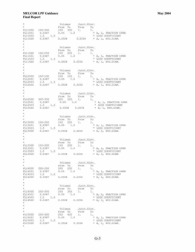
MELCOR LPF Guidance May 2004 Final Report
G-3
* Volumes Junct.Elev. * From To From To FL11000 100-300 100 300 1. 1. FL11001 0.0387 0.05 1.0 * A, L, FRACTION OPEN FL11003 1.5 1.5 * LOSS COEFFICIENT FL110S0 0.0387 0.0508 0.0254 * A, L, HYD.DIAM. * * * Volumes Junct.Elev. * From To From To FL11500 100-250 100 250 1. 1. FL11501 0.0387 0.05 1.0 * A, L, FRACTION OPEN FL11503 1.5 1.5 * LOSS COEFFICIENT FL115S0 0.0387 0.0508 0.0254 * A, L, HYD.DIAM. * * * Volumes Junct.Elev. * From To From To FL12000 150-100 150 100 1. 1. FL12001 0.0387 0.05 1.0 * A, L, FRACTION OPEN FL12003 1.5 1.5 * LOSS COEFFICIENT FL120S0 0.0387 0.0508 0.0254 * A, L, HYD.DIAM. * * * Volumes Junct.Elev. * From To From To FL12500 300-350 300 350 1. 1. FL12501 0.0387 0.05 1.0 * A, L, FRACTION OPEN FL12503 1.5 1.5 * LOSS COEFFICIENT FL125S0 0.0387 0.0508 0.0254 * A, L, HYD.DIAM. * * * Volumes Junct.Elev. * From To From To FL13000 150-250 150 250 1. 1. FL13001 0.0387 0.05 1.0 * A, L, FRACTION OPEN FL13003 1.5 1.5 * LOSS COEFFICIENT FL130S0 0.0387 0.0508 0.0254 * A, L, HYD.DIAM. * * * Volumes Junct.Elev. * From To From To FL13500 150-200 150 200 1. 1. FL13501 0.0387 0.05 1.0 * A, L, FRACTION OPEN FL13503 1.5 1.5 * LOSS COEFFICIENT FL135S0 0.0387 0.0508 0.0254 * A, L, HYD.DIAM. * * * Volumes Junct.Elev. * From To From To FL14000 200-250 200 250 1. 1. FL14001 0.0387 0.05 1.0 * A, L, FRACTION OPEN FL14003 1.5 1.5 * LOSS COEFFICIENT FL140S0 0.0387 0.0508 0.0254 * A, L, HYD.DIAM. * * * Volumes Junct.Elev. * From To From To FL14500 250-350 250 350 1. 1. FL14501 0.0387 0.05 1.0 * A, L, FRACTION OPEN FL14503 1.5 1.5 * LOSS COEFFICIENT FL145S0 0.0387 0.0508 0.0254 * A, L, HYD.DIAM. * * * Volumes Junct.Elev. * From To From To FL15000 250-400 250 400 1. 1. FL15001 0.0387 0.05 1.0 * A, L, FRACTION OPEN FL15003 1.5 1.5 * LOSS COEFFICIENT FL150S0 0.0387 0.0508 0.0254 * A, L, HYD.DIAM. *
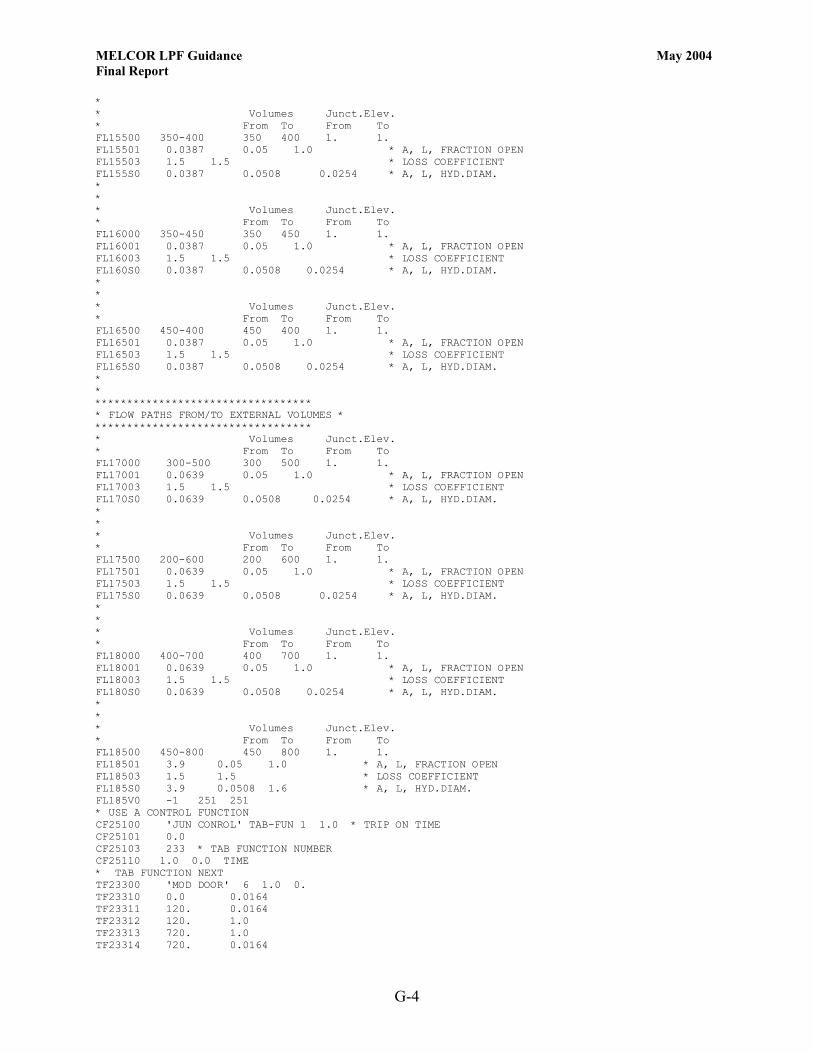
MELCOR LPF Guidance May 2004 Final Report
G-4
* * Volumes Junct.Elev. * From To From To FL15500 350-400 350 400 1. 1. FL15501 0.0387 0.05 1.0 * A, L, FRACTION OPEN FL15503 1.5 1.5 * LOSS COEFFICIENT FL155S0 0.0387 0.0508 0.0254 * A, L, HYD.DIAM. * * * Volumes Junct.Elev. * From To From To FL16000 350-450 350 450 1. 1. FL16001 0.0387 0.05 1.0 * A, L, FRACTION OPEN FL16003 1.5 1.5 * LOSS COEFFICIENT FL160S0 0.0387 0.0508 0.0254 * A, L, HYD.DIAM. * * * Volumes Junct.Elev. * From To From To FL16500 450-400 450 400 1. 1. FL16501 0.0387 0.05 1.0 * A, L, FRACTION OPEN FL16503 1.5 1.5 * LOSS COEFFICIENT FL165S0 0.0387 0.0508 0.0254 * A, L, HYD.DIAM. * * ********************************** * FLOW PATHS FROM/TO EXTERNAL VOLUMES * ********************************** * Volumes Junct.Elev. * From To From To FL17000 300-500 300 500 1. 1. FL17001 0.0639 0.05 1.0 * A, L, FRACTION OPEN FL17003 1.5 1.5 * LOSS COEFFICIENT FL170S0 0.0639 0.0508 0.0254 * A, L, HYD.DIAM. * * * Volumes Junct.Elev. * From To From To FL17500 200-600 200 600 1. 1. FL17501 0.0639 0.05 1.0 * A, L, FRACTION OPEN FL17503 1.5 1.5 * LOSS COEFFICIENT FL175S0 0.0639 0.0508 0.0254 * A, L, HYD.DIAM. * * * Volumes Junct.Elev. * From To From To FL18000 400-700 400 700 1. 1. FL18001 0.0639 0.05 1.0 * A, L, FRACTION OPEN FL18003 1.5 1.5 * LOSS COEFFICIENT FL180S0 0.0639 0.0508 0.0254 * A, L, HYD.DIAM. * * * Volumes Junct.Elev. * From To From To FL18500 450-800 450 800 1. 1. FL18501 3.9 0.05 1.0 * A, L, FRACTION OPEN FL18503 1.5 1.5 * LOSS COEFFICIENT FL185S0 3.9 0.0508 1.6 * A, L, HYD.DIAM. FL185V0 -1 251 251 * USE A CONTROL FUNCTION CF25100 'JUN CONROL' TAB-FUN 1 1.0 * TRIP ON TIME CF25101 0.0 CF25103 233 * TAB FUNCTION NUMBER CF25110 1.0 0.0 TIME * TAB FUNCTION NEXT TF23300 'MOD DOOR' 6 1.0 0. TF23310 0.0 0.0164 TF23311 120. 0.0164 TF23312 120. 1.0 TF23313 720. 1.0 TF23314 720. 0.0164
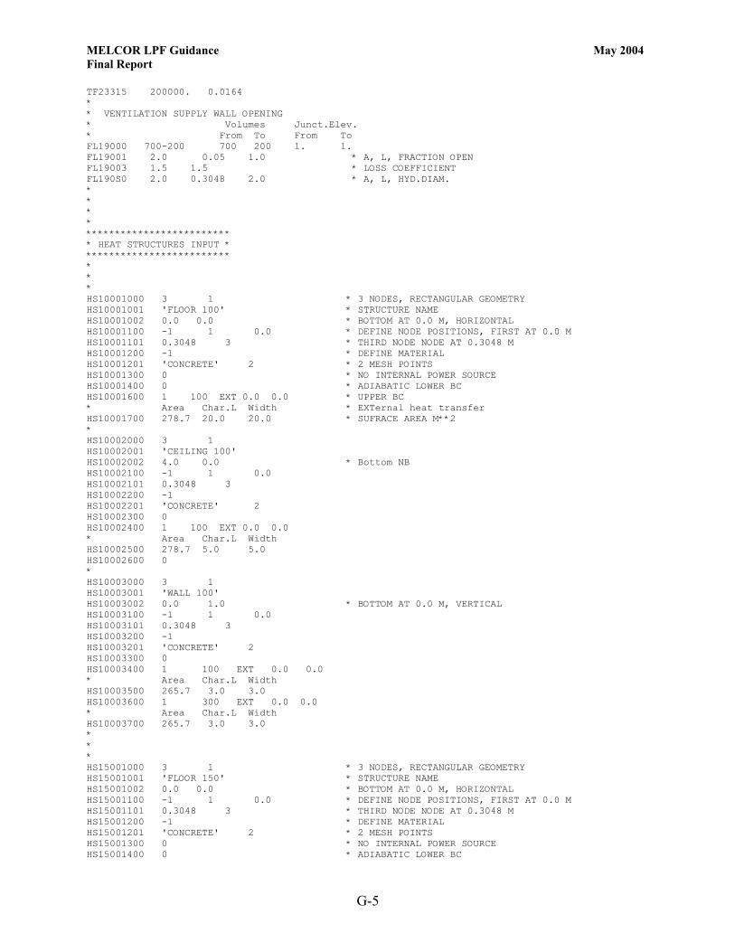
MELCOR LPF Guidance May 2004 Final Report
G-5
TF23315 200000. 0.0164 * * VENTILATION SUPPLY WALL OPENING * Volumes Junct.Elev. * From To From To FL19000 700-200 700 200 1. 1. FL19001 2.0 0.05 1.0 * A, L, FRACTION OPEN FL19003 1.5 1.5 * LOSS COEFFICIENT FL190S0 2.0 0.3048 2.0 * A, L, HYD.DIAM. * * * * ************************* * HEAT STRUCTURES INPUT * ************************* * * * HS10001000 3 1 * 3 NODES, RECTANGULAR GEOMETRY HS10001001 'FLOOR 100' * STRUCTURE NAME HS10001002 0.0 0.0 * BOTTOM AT 0.0 M, HORIZONTAL HS10001100 -1 1 0.0 * DEFINE NODE POSITIONS, FIRST AT 0.0 M HS10001101 0.3048 3 * THIRD NODE NODE AT 0.3048 M HS10001200 -1 * DEFINE MATERIAL HS10001201 'CONCRETE' 2 * 2 MESH POINTS HS10001300 0 * NO INTERNAL POWER SOURCE HS10001400 0 * ADIABATIC LOWER BC HS10001600 1 100 EXT 0.0 0.0 * UPPER BC * Area Char.L Width * EXTernal heat transfer HS10001700 278.7 20.0 20.0 * SUFRACE AREA M**2 * HS10002000 3 1 HS10002001 'CEILING 100' HS10002002 4.0 0.0 * Bottom NB HS10002100 -1 1 0.0 HS10002101 0.3048 3 HS10002200 -1 HS10002201 'CONCRETE' 2 HS10002300 0 HS10002400 1 100 EXT 0.0 0.0 * Area Char.L Width HS10002500 278.7 5.0 5.0 HS10002600 0 * HS10003000 3 1 HS10003001 'WALL 100' HS10003002 0.0 1.0 * BOTTOM AT 0.0 M, VERTICAL HS10003100 -1 1 0.0 HS10003101 0.3048 3 HS10003200 -1 HS10003201 'CONCRETE' 2 HS10003300 0 HS10003400 1 100 EXT 0.0 0.0 * Area Char.L Width HS10003500 265.7 3.0 3.0 HS10003600 1 300 EXT 0.0 0.0 * Area Char.L Width HS10003700 265.7 3.0 3.0 * * * HS15001000 3 1 * 3 NODES, RECTANGULAR GEOMETRY HS15001001 'FLOOR 150' * STRUCTURE NAME HS15001002 0.0 0.0 * BOTTOM AT 0.0 M, HORIZONTAL HS15001100 -1 1 0.0 * DEFINE NODE POSITIONS, FIRST AT 0.0 M HS15001101 0.3048 3 * THIRD NODE NODE AT 0.3048 M HS15001200 -1 * DEFINE MATERIAL HS15001201 'CONCRETE' 2 * 2 MESH POINTS HS15001300 0 * NO INTERNAL POWER SOURCE HS15001400 0 * ADIABATIC LOWER BC
MELCOR LPF Guidance May 2004 Final Report
G-6
HS15001600 1 150 EXT 0.0 0.0 * UPPER BC * Area Char.L Width * EXTernal heat transfer HS15001700 426.4 20.0 20.0 * SUFRACE AREA M**2 * HS15002000 3 1 HS15002001 'CEILING 150' HS15002002 4.0 0.0 * Bottom NB HS15002100 -1 1 0.0 HS15002101 0.3048 3 HS15002200 -1 HS15002201 'CONCRETE' 2 HS15002300 0 HS15002400 1 150 EXT 0.0 0.0 * Area Char.L Width HS15002500 426.4 5.0 5.0 HS15002600 0 * HS15003000 3 1 HS15003001 'WALL 150' HS15003002 0.0 1.0 * BOTTOM AT 0.0 M, VERTICAL HS15003100 -1 1 0.0 HS15003101 0.3048 3 HS15003200 -1 HS15003201 'CONCRETE' 2 HS15003300 0 HS15003400 1 150 EXT 0.0 0.0 * Area Char.L Width HS15003500 335.8 3.0 3.0 HS15003600 1 300 EXT 0.0 0.0 * Area Char.L Width HS15003700 335.8 3.0 3.0 * * * HS20001000 3 1 * 3 NODES, RECTANGULAR GEOMETRY HS20001001 'FLOOR 200' * STRUCTURE NAME HS20001002 0.0 0.0 * BOTTOM AT 0.0 M, HORIZONTAL HS20001100 -1 1 0.0 * DEFINE NODE POSITIONS, FIRST AT 0.0 M HS20001101 0.3048 3 * THIRD NODE NODE AT 0.3048 M HS20001200 -1 * DEFINE MATERIAL HS20001201 'CONCRETE' 2 * 2 MESH POINTS HS20001300 0 * NO INTERNAL POWER SOURCE HS20001400 0 * ADIABATIC LOWER BC HS20001600 1 200 EXT 0.0 0.0 * UPPER BC * Area Char.L Width * EXTernal heat transfer HS20001700 426.4 20.0 20.0 * SUFRACE AREA M**2 * HS20002000 3 1 HS20002001 'CEILING 200' HS20002002 4.0 0.0 * Bottom NB HS20002100 -1 1 0.0 HS20002101 0.3048 3 HS20002200 -1 HS20002201 'CONCRETE' 2 HS20002300 0 HS20002400 1 200 EXT 0.0 0.0 * Area Char.L Width HS20002500 426.4 5.0 5.0 HS20002600 0 * HS20003000 3 1 HS20003001 'WALL 200' HS20003002 0.0 1.0 * BOTTOM AT 0.0 M, VERTICAL HS20003100 -1 1 0.0 HS20003101 0.3048 3 HS20003200 -1 HS20003201 'CONCRETE' 2 HS20003300 0 HS20003400 1 200 EXT 0.0 0.0 * Area Char.L Width HS20003500 335.8 3.0 3.0

MELCOR LPF Guidance May 2004 Final Report
G-7
HS20003600 1 300 EXT 0.0 0.0 * Area Char.L Width HS20003700 335.8 3.0 3.0 * * * HS25001000 3 1 * 3 NODES, RECTANGULAR GEOMETRY HS25001001 'FLOOR 250' * STRUCTURE NAME HS25001002 0.0 0.0 * BOTTOM AT 0.0 M, HORIZONTAL HS25001100 -1 1 0.0 * DEFINE NODE POSITIONS, FIRST AT 0.0 M HS25001101 0.3048 3 * THIRD NODE NODE AT 0.3048 M HS25001200 -1 * DEFINE MATERIAL HS25001201 'CONCRETE' 2 * 2 MESH POINTS HS25001300 0 * NO INTERNAL POWER SOURCE HS25001400 0 * ADIABATIC LOWER BC HS25001600 1 250 EXT 0.0 0.0 * UPPER BC * Area Char.L Width * EXTernal heat transfer HS25001700 94.8 20.0 20.0 * SUFRACE AREA M**2 * HS25002000 3 1 HS25002001 'CEILING 250' HS25002002 4.0 0.0 * Bottom NB HS25002100 -1 1 0.0 HS25002101 0.3048 3 HS25002200 -1 HS25002201 'CONCRETE' 2 HS25002300 0 HS25002400 1 250 EXT 0.0 0.0 * Area Char.L Width HS25002500 94.8 5.0 5.0 HS25002600 0 * HS25003000 3 1 HS25003001 'WALL 250' HS25003002 0.0 1.0 * BOTTOM AT 0.0 M, VERTICAL HS25003100 -1 1 0.0 HS25003101 0.3048 3 HS25003200 -1 HS25003201 'CONCRETE' 2 HS25003300 0 HS25003400 1 250 EXT 0.0 0.0 * Area Char.L Width HS25003500 425.1 3.0 3.0 HS25003600 1 300 EXT 0.0 0.0 * Area Char.L Width HS25003700 425.1 3.0 3.0 * * * HS30001000 3 1 * 3 NODES, RECTANGULAR GEOMETRY HS30001001 'FLOOR 300' * STRUCTURE NAME HS30001002 0.0 0.0 * BOTTOM AT 0.0 M, HORIZONTAL HS30001100 -1 1 0.0 * DEFINE NODE POSITIONS, FIRST AT 0.0 M HS30001101 0.3048 3 * THIRD NODE NODE AT 0.3048 M HS30001200 -1 * DEFINE MATERIAL HS30001201 'CONCRETE' 2 * 2 MESH POINTS HS30001300 0 * NO INTERNAL POWER SOURCE HS30001400 0 * ADIABATIC LOWER BC HS30001600 1 300 EXT 0.0 0.0 * UPPER BC * Area Char.L Width * EXTernal heat transfer HS30001700 209. 20.0 20.0 * SUFRACE AREA M**2 * HS30002000 3 1 HS30002001 'CEILING 300' HS30002002 4.0 0.0 * Bottom NB HS30002100 -1 1 0.0 HS30002101 0.3048 3 HS30002200 -1 HS30002201 'CONCRETE' 2 HS30002300 0 HS30002400 1 300 EXT 0.0 0.0
MELCOR LPF Guidance May 2004 Final Report
G-8
* Area Char.L Width HS30002500 209. 5.0 5.0 HS30002600 0 * HS30003000 3 1 HS30003001 'WALL 300' HS30003002 0.0 1.0 * BOTTOM AT 0.0 M, VERTICAL HS30003100 -1 1 0.0 HS30003101 0.3048 3 HS30003200 -1 HS30003201 'CONCRETE' 2 HS30003300 0 HS30003400 1 300 EXT 0.0 0.0 * Area Char.L Width HS30003500 229.5 3.0 3.0 HS30003600 1 150 EXT 0.0 0.0 * Area Char.L Width HS30003700 229.5 3.0 3.0 * * * HS35001000 3 1 * 3 NODES, RECTANGULAR GEOMETRY HS35001001 'FLOOR 350' * STRUCTURE NAME HS35001002 0.0 0.0 * BOTTOM AT 0.0 M, HORIZONTAL HS35001100 -1 1 0.0 * DEFINE NODE POSITIONS, FIRST AT 0.0 M HS35001101 0.3048 3 * THIRD NODE NODE AT 0.3048 M HS35001200 -1 * DEFINE MATERIAL HS35001201 'CONCRETE' 2 * 2 MESH POINTS HS35001300 0 * NO INTERNAL POWER SOURCE HS35001400 0 * ADIABATIC LOWER BC HS35001600 1 350 EXT 0.0 0.0 * UPPER BC * Area Char.L Width * EXTernal heat transfer HS35001700 325.2 20.0 20.0 * SUFRACE AREA M**2 * HS35002000 3 1 HS35002001 'CEILING 350' HS35002002 4.0 0.0 * Bottom NB HS35002100 -1 1 0.0 HS35002101 0.3048 3 HS35002200 -1 HS35002201 'CONCRETE' 2 HS35002300 0 HS35002400 1 350 EXT 0.0 0.0 * Area Char.L Width HS35002500 325.2 5.0 5.0 HS35002600 0 * HS35003000 3 1 HS35003001 'WALL 350' HS35003002 0.0 1.0 * BOTTOM AT 0.0 M, VERTICAL HS35003100 -1 1 0.0 HS35003101 0.3048 3 HS35003200 -1 HS35003201 'CONCRETE' 2 HS35003300 0 HS35003400 1 350 EXT 0.0 0.0 * Area Char.L Width HS35003500 326.1 3.0 3.0 HS35003600 1 150 EXT 0.0 0.0 * Area Char.L Width HS35003700 326.1 3.0 3.0 * * * HS40001000 3 1 * 3 NODES, RECTANGULAR GEOMETRY HS40001001 'FLOOR 400' * STRUCTURE NAME HS40001002 0.0 0.0 * BOTTOM AT 0.0 M, HORIZONTAL HS40001100 -1 1 0.0 * DEFINE NODE POSITIONS, FIRST AT 0.0 M HS40001101 0.3048 3 * THIRD NODE NODE AT 0.3048 M HS40001200 -1 * DEFINE MATERIAL HS40001201 'CONCRETE' 2 * 2 MESH POINTS

MELCOR LPF Guidance May 2004 Final Report
G-9
HS40001300 0 * NO INTERNAL POWER SOURCE HS40001400 0 * ADIABATIC LOWER BC HS40001600 1 400 EXT 0.0 0.0 * UPPER BC * Area Char.L Width * EXTernal heat transfer HS40001700 292.6 20.0 20.0 * SUFRACE AREA M**2 * HS40002000 3 1 HS40002001 'CEILING 400' HS40002002 4.0 0.0 * Bottom NB HS40002100 -1 1 0.0 HS40002101 0.3048 3 HS40002200 -1 HS40002201 'CONCRETE' 2 HS40002300 0 HS40002400 1 400 EXT 0.0 0.0 * Area Char.L Width HS40002500 292.6 5.0 5.0 HS40002600 0 * HS40003000 3 1 HS40003001 'WALL 400' HS40003002 0.0 1.0 * BOTTOM AT 0.0 M, VERTICAL HS40003100 -1 1 0.0 HS40003101 0.3048 3 HS40003200 -1 HS40003201 'CONCRETE' 2 HS40003300 0 HS40003400 1 400 EXT 0.0 0.0 * Area Char.L Width HS40003500 277.8 3.0 3.0 HS40003600 1 150 EXT 0.0 0.0 * Area Char.L Width HS40003700 277.8 3.0 3.0 * * * HS45001000 3 1 * 3 NODES, RECTANGULAR GEOMETRY HS45001001 'FLOOR 450' * STRUCTURE NAME HS45001002 0.0 0.0 * BOTTOM AT 0.0 M, HORIZONTAL HS45001100 -1 1 0.0 * DEFINE NODE POSITIONS, FIRST AT 0.0 M HS45001101 0.3048 3 * THIRD NODE NODE AT 0.3048 M HS45001200 -1 * DEFINE MATERIAL HS45001201 'CONCRETE' 2 * 2 MESH POINTS HS45001300 0 * NO INTERNAL POWER SOURCE HS45001400 0 * ADIABATIC LOWER BC HS45001600 1 450 EXT 0.0 0.0 * UPPER BC * Area Char.L Width * EXTernal heat transfer HS45001700 92.9 20.0 20.0 * SUFRACE AREA M**2 * HS45002000 3 1 HS45002001 'CEILING 450' HS45002002 4.0 0.0 * Bottom NB HS45002100 -1 1 0.0 HS45002101 0.3048 3 HS45002200 -1 HS45002201 'CONCRETE' 2 HS45002300 0 HS45002400 1 450 EXT 0.0 0.0 * Area Char.L Width HS45002500 92.9 5.0 5.0 HS45002600 0 * HS45003000 3 1 HS45003001 'WALL 450' HS45003002 0.0 1.0 * BOTTOM AT 0.0 M, VERTICAL HS45003100 -1 1 0.0 HS45003101 0.3048 3 HS45003200 -1 HS45003201 'CONCRETE' 2 HS45003300 0 HS45003400 1 450 EXT 0.0 0.0

MELCOR LPF Guidance May 2004 Final Report
G-10
* Area Char.L Width HS45003500 265.7 3.0 3.0 HS45003600 1 150 EXT 0.0 0.0 * Area Char.L Width HS45003700 265.7 3.0 3.0 * * * HS50001000 3 1 HS50001001 'FLOOR 500' HS50001002 0.0 0.0 HS50001100 -1 1 0.0 HS50001101 0.3 3 HS50001200 -1 HS50001201 'CONCRETE' 2 HS50001300 0 HS50001400 0 HS50001600 1 500 EXT 0.0 0.0 HS50001700 0.0001 0.0001 0.0001 * AREA * * * HS60001000 3 1 HS60001001 'FLOOR 600' HS60001002 0.0 0.0 HS60001100 -1 1 0.0 HS60001101 0.3 3 HS60001200 -1 HS60001201 'CONCRETE' 2 HS60001300 0 HS60001400 0 HS60001600 1 600 EXT 0.0 0.0 HS60001700 0.0001 0.0001 0.0001 * AREA * * * HS70001000 3 1 HS70001001 'FLOOR 700' HS70001002 0.0 0.0 HS70001100 -1 1 0.0 HS70001101 0.3 3 HS70001200 -1 HS70001201 'CONCRETE' 2 HS70001300 0 HS70001400 0 HS70001600 1 700 EXT 0.0 0.0 HS70001700 0.0001 0.0001 0.0001 * AREA * * * HS80001000 3 1 HS80001001 'FLOOR 800' HS80001002 0.0 0.0 HS80001100 -1 1 0.0 HS80001101 0.3 3 HS80001200 -1 HS80001201 'CONCRETE' 2 HS80001300 0 HS80001400 0 HS80001600 1 800 EXT 0.0 0.0 HS80001700 0.0001 0.0001 0.0001 * AREA * * AEROSOL SECTION RN1000 0 * ACTIVATE RNCA100 0 * NOT ACTIVE RN1001 20 2 17 0 0 3 0 RN1100 1.0e-8 3.0e-6 11.46E+3 RNACOEF 1 RNAS000 350 2 1 1. 1.0 601 2

MELCOR LPF Guidance May 2004 Final Report
G-11
RNAS001 2.3e-6 2. RNAS002 200 2 1 1. 1.0 602 2 RNAS003 2.3e-6 2. RNAS004 250 2 1 1. 1.0 603 2 RNAS005 2.3e-6 2. * DEFINE TABULAR FUNCTION AEROSOL RELEASE RATE * TF60100 'AEROSOL1' 5 1.0 TF60110 0.0 0.000 * TIME KG RELEASE TF60111 10.0 0.000 TF60112 11.0 0.3 TF60113 12.0 0.0 TF60114 200000. 0.0 TF60200 'AEROSOL2' 5 1.0 TF60210 0.0 0.000 * TIME KG RELEASE TF60211 10.0 0.000 TF60212 11.0 0.3 TF60213 12.0 0.0 TF60214 200000. 0.0 TF60300 'AEROSOL3' 5 1.0 TF60310 0.0 0.000 * TIME KG RELEASE TF60311 10.0 0.000 TF60312 11.0 0.4 TF60313 12.0 0.0 TF60314 200000. 0.0 . *eor* melcor * ********************************** * MELCOR INPUT * ********************************** * TITLE 'TEST PROBLEM' * RESTART 0 * RESTART FROM CYCLE 0 * TEND 72000.0 * END TIME S * CPULIM 100000.0 CPULEFT 20.0 * CRTOUT * 80-COLUMN OUTPUT FORMAT * ********* * FILES * ********* * RESTARTFILE SAMPLE.RST OUTPUTFILE SAMPLE.OUT PLOTFILE SAMPLE.PTF DIAGFILE SAMPLE.DIA MESSAGEFILE SAMPLE.MES * ****************************** * TIME STEP AND EDIT CONTROL * ****************************** * TIME DTMAX DTMIN DTEDT DTPLT DTRST TIME1 0.0 0.1 0.000000001 5.0 100.0 10.0 TIME2 1000.0 10.0 0.000000001 500.0 100.0 1000.0 TIME3 1100.0 30.0 0.000000001 500.0 100.0 1000.0 TIME4 1300.0 100.0 0.000000001 1000.0 200.0 5000.0 TIME5 2500.0 200.0 0.000000001 1000.0 200.0 5000.0 .


![MELCOR Computer Code Manuals · PDF fileThis publication of the MELCOR computer code manuals corresponds to MELCOR 1.8.5, ... of Volume 1 contains the MELCOR User’s Guides, ... [1]](https://img.pdfslide.us/doc/110x75/5a86a7f27f8b9a87368dc173/melcor-computer-code-manuals-publication-of-the-melcor-computer-code-manuals-corresponds.jpg)