Embed Size (px)
Citation preview
MEITRACK MVT600 User Guide
MEITRACK MVT600 User Guide
MEITRACK MVT600 User Guide
Copyright © 2017 Meitrack Group All rights reserved. - 2 -
Change History File Name MEITRACK MVT600 User Guide Created By Kyle Lv
Project MVT600 Creation Date
Update Date
2010-08-30
2017-03-24
Subproject User Guide Total Pages 17
Version V3.5 Confidential External Documentation
MEITRACK MVT600 User Guide
Copyright © 2017 Meitrack Group All rights reserved. - 3 -
Contents 1 Copyright and Disclaimer ...............................................................................................................................................................- 4 -
2 Product Overview ..........................................................................................................................................................................- 4 -
3 Product Functions and Specifications ............................................................................................................................................- 4 -
3.1 Product Functions ...............................................................................................................................................................- 4 -
3.1.1 Position Tracking ......................................................................................................................................................- 4 -
3.1.2 Anti-Theft .................................................................................................................................................................- 4 -
3.1.3 Functions of Optional Accessories ...........................................................................................................................- 5 -
3.1.4 Other Functions .......................................................................................................................................................- 5 -
3.2 Specifications ......................................................................................................................................................................- 5 -
4 MVT600 and Accessories ...............................................................................................................................................................- 6 -
5 Appearance....................................................................................................................................................................................- 7 -
6 First Use .........................................................................................................................................................................................- 7 -
6.1 Installing the SIM Card ........................................................................................................................................................- 7 -
6.2 Charging the Device ............................................................................................................................................................- 8 -
6.3 LED Indicator .......................................................................................................................................................................- 8 -
6.4 Configuring Device Parameters by Meitrack Manager .......................................................................................................- 8 -
6.5 Tracking by Mobile Phone ...................................................................................................................................................- 9 -
6.6 Common SMS Commands ................................................................................................................................................- 10 -
6.6.1 Setting Authorized Phone Numbers – A71 ............................................................................................................- 10 -
6.6.2 Setting the Smart Sleep Mode – A73 .....................................................................................................................- 10 -
7 Logging In to MS03 Tracking System ............................................................................................................................................- 11 -
8 Installing the MVT600 ..................................................................................................................................................................- 11 -
8.1 Installing GPS and GSM Antennas .....................................................................................................................................- 11 -
8.2 Installing an I/O Cable .......................................................................................................................................................- 12 -
8.3 Wiring Diagram .................................................................................................................................................................- 13 -
8.3.1 Power Cable/Ground Wire (Pin 1/2) ......................................................................................................................- 13 -
8.3.2 Checking Vehicle Door Status and Trunk Status (Pin 4/5, Negative Trigger) ..........................................................- 13 -
8.3.3 Checking Engine Status (Pin 3, Positive Trigger) .....................................................................................................- 14 -
8.3.4 Fuel/Power Cut-off (Pin 7/9/11) ............................................................................................................................- 14 -
8.3.5 Sensor Input (Pin 8/10/12) ....................................................................................................................................- 14 -
8.3.6 Installing the Handset (RS232 Port) .......................................................................................................................- 14 -
8.3.7 Installing a Camera (RS232 Port) ............................................................................................................................- 15 -
8.3.8 Installing the Micro SD Card ...................................................................................................................................- 16 -
8.3.9 Installing the RFID Reader (Start the Engine) .........................................................................................................- 16 -
8.4 Mounting the MVT600 .....................................................................................................................................................- 16 -
MEITRACK MVT600 User Guide
Copyright © 2017 Meitrack Group All rights reserved. - 4 -
1 Copyright and Disclaimer
Copyright © 2017 MEITRACK. All rights reserved.
and are trademarks that belong to Meitrack Group.
The user manual may be changed without notice.
Without prior written consent of Meitrack Group, this user manual, or any part thereof, may not be reproduced for any
purpose whatsoever, or transmitted in any form, either electronically or mechanically, including photocopying and recording.
Meitrack Group shall not be liable for direct, indirect, special, incidental, or consequential damages (including but not limited to
economic losses, personal injuries, and loss of assets and property) caused by the use, inability, or illegality to use the product
or documentation.
2 Product Overview
The MVT600 is a high-end GPS vehicle tracker supporting GPS, GSM, and GPRS functions. It can connect to a variety of
peripherals, such as the camera, handset, LCD display, LED display, and RFID reader. This ensures high expansion.
The MVT600 is specialized in tracking, monitoring, and protection of commercial vehicles in the delivery, logistics, taxi, and bus
industries.
3 Product Functions and Specifications
3.1 Product Functions
3.1.1 Position Tracking
GPS + GSM positioning
Real-time location query
Track by time interval
Track by distance
Track by mobile phone
Speeding alarm
Cornering report
3.1.2 Anti-Theft
SOS alarm
GPS antenna cut-off alarm
External power supply cut-off alarm
GPS blind spot alarm
Low power alarm
Remote vehicle fuel/power cut-off
Towing alarm
Engine or vehicle door status alarm
Geo-fence
MEITRACK MVT600 User Guide
Copyright © 2017 Meitrack Group All rights reserved. - 5 -
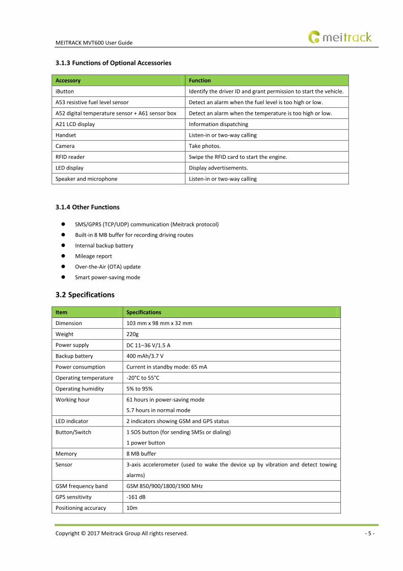
3.1.3 Functions of Optional Accessories
Accessory Function
iButton Identify the driver ID and grant permission to start the vehicle.
A53 resistive fuel level sensor Detect an alarm when the fuel level is too high or low.
A52 digital temperature sensor + A61 sensor box Detect an alarm when the temperature is too high or low.
A21 LCD display Information dispatching
Handset Listen-in or two-way calling
Camera Take photos.
RFID reader Swipe the RFID card to start the engine.
LED display Display advertisements.
Speaker and microphone Listen-in or two-way calling
3.1.4 Other Functions
SMS/GPRS (TCP/UDP) communication (Meitrack protocol)
Built-in 8 MB buffer for recording driving routes
Internal backup battery
Mileage report
Over-the-Air (OTA) update
Smart power-saving mode
3.2 Specifications
Item Specifications
Dimension 103 mm x 98 mm x 32 mm
Weight 220g
Power supply DC 11–36 V/1.5 A
Backup battery 400 mAh/3.7 V
Power consumption Current in standby mode: 65 mA
Operating temperature -20°C to 55°C
Operating humidity 5% to 95%
Working hour 61 hours in power-saving mode
5.7 hours in normal mode
LED indicator 2 indicators showing GSM and GPS status
Button/Switch 1 SOS button (for sending SMSs or dialing)
1 power button
Memory 8 MB buffer
Sensor 3-axis accelerometer (used to wake the device up by vibration and detect towing
alarms)
GSM frequency band GSM 850/900/1800/1900 MHz
GPS sensitivity -161 dB
Positioning accuracy 10m
MEITRACK MVT600 User Guide
Copyright © 2017 Meitrack Group All rights reserved. - 6 -
I/O port 3 inputs (2 negative inputs and 1 positive input)
1 analog detection input
1 fuel level sensor detection input
1 digital temperature sensor detection input
3 outputs
4 RS232 ports
1 Wiegand port
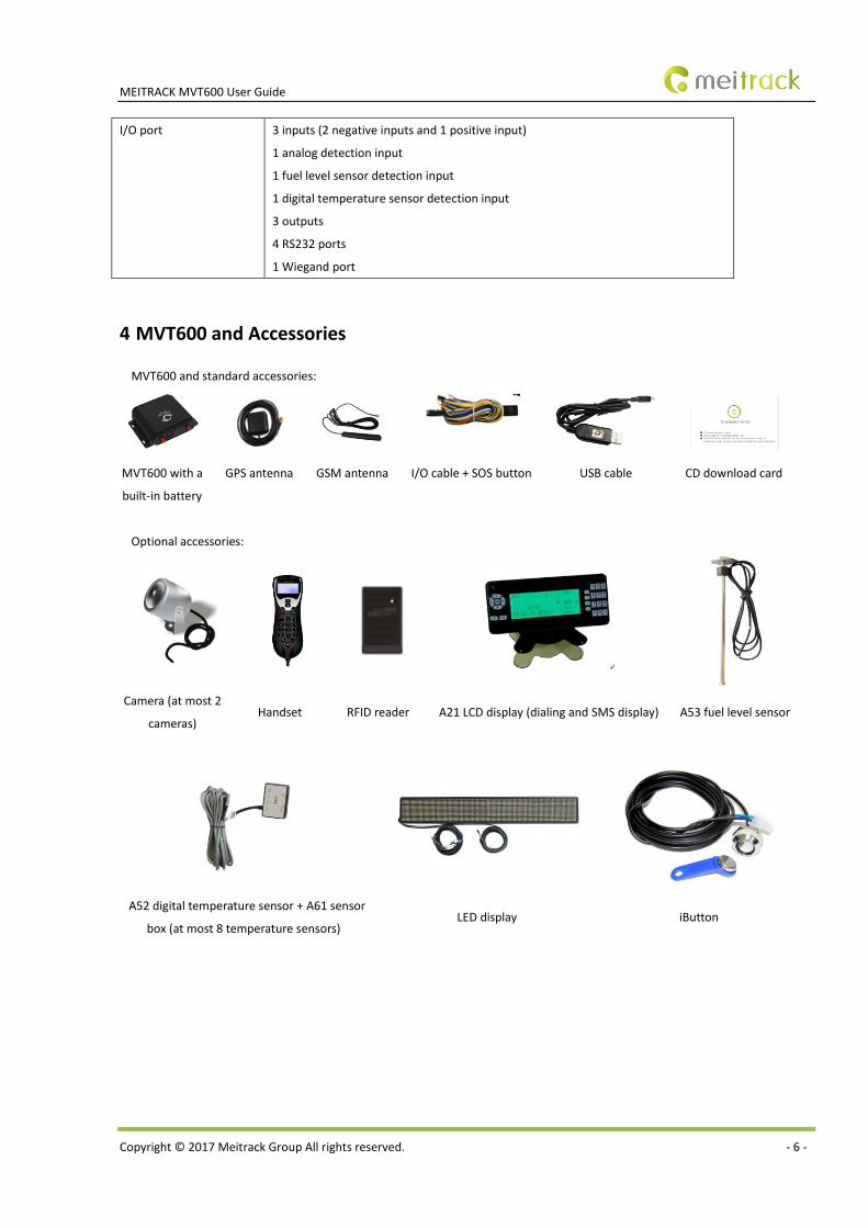
4 MVT600 and Accessories
MVT600 and standard accessories:
MVT600 with a
built-in battery
GPS antenna GSM antenna I/O cable + SOS button USB cable CD download card
Optional accessories:
Camera (at most 2
cameras) Handset RFID reader A21 LCD display (dialing and SMS display) A53 fuel level sensor
A52 digital temperature sensor + A61 sensor
box (at most 8 temperature sensors) LED display iButton
MEITRACK MVT600 User Guide
Copyright © 2017 Meitrack Group All rights reserved. - 7 -
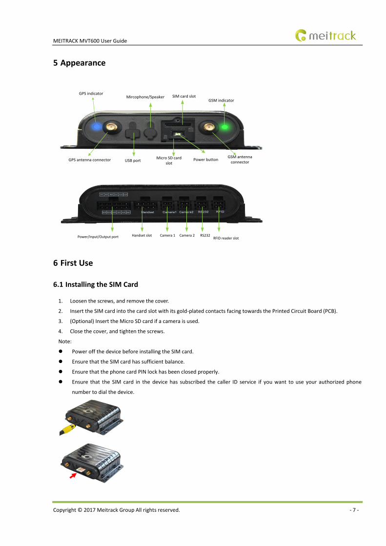
5 Appearance
GPS indicatorMircophone/Speaker SIM card slot
GSM indicator
GPS antenna connector USB portMicro SD card
slotPower button
GSM antenna connector
Power/Input/Output port
Handset slot
Camera 1
Camera 2 RS232RFID reader slot
6 First Use
6.1 Installing the SIM Card
1. Loosen the screws, and remove the cover.
2. Insert the SIM card into the card slot with its gold-plated contacts facing towards the Printed Circuit Board (PCB).
3. (Optional) Insert the Micro SD card if a camera is used.
4. Close the cover, and tighten the screws.
Note:
Power off the device before installing the SIM card.
Ensure that the SIM card has sufficient balance.
Ensure that the phone card PIN lock has been closed properly.
Ensure that the SIM card in the device has subscribed the caller ID service if you want to use your authorized phone
number to dial the device.
MEITRACK MVT600 User Guide
Copyright © 2017 Meitrack Group All rights reserved. - 8 -
6.2 Charging the Device
When you use the device for the first time, connect the device's GND (-Black) and Power (+Red) wires to 12 V or 24 V external
power supply for charging. Ensure that the device is charged at least three hours. Eight hours are recommended.
The device can be installed on a vehicle only after it is configured and tested.
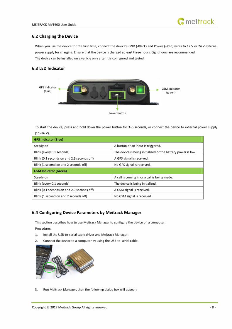
6.3 LED Indicator
GPS indicator (blue)
Power button
GSM indicator (green)
To start the device, press and hold down the power button for 3–5 seconds, or connect the device to external power supply
(11–36 V).
GPS Indicator (Blue)
Steady on A button or an input is triggered.
Blink (every 0.1 seconds) The device is being initialized or the battery power is low.
Blink (0.1 seconds on and 2.9 seconds off) A GPS signal is received.
Blink (1 second on and 2 seconds off) No GPS signal is received.
GSM Indicator (Green)
Steady on A call is coming in or a call is being made.
Blink (every 0.1 seconds) The device is being initialized.
Blink (0.1 seconds on and 2.9 seconds off) A GSM signal is received.
Blink (1 second on and 2 seconds off) No GSM signal is received.
6.4 Configuring Device Parameters by Meitrack Manager
This section describes how to use Meitrack Manager to configure the device on a computer.
Procedure:
1. Install the USB-to-serial cable driver and Meitrack Manager.
2. Connect the device to a computer by using the USB-to-serial cable.
3. Run Meitrack Manager, then the following dialog box will appear:
MEITRACK MVT600 User Guide
Copyright © 2017 Meitrack Group All rights reserved. - 9 -
Turn on the device, then Meitrack Manager will detect the device model automatically and the parameter page will appear
accordingly.
For details about Meitrack Manager, see the MEITRACK Manager User Guide.
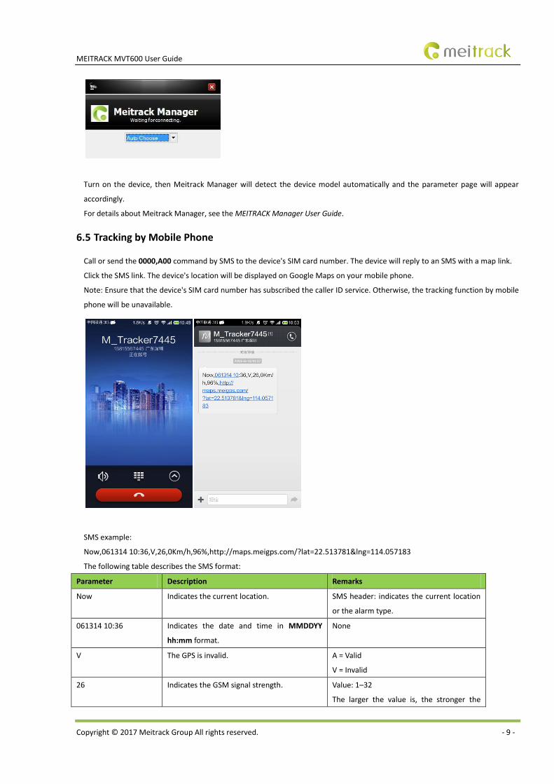
6.5 Tracking by Mobile Phone
Call or send the 0000,A00 command by SMS to the device's SIM card number. The device will reply to an SMS with a map link.
Click the SMS link. The device's location will be displayed on Google Maps on your mobile phone.
Note: Ensure that the device's SIM card number has subscribed the caller ID service. Otherwise, the tracking function by mobile
phone will be unavailable.
SMS example:
Now,061314 10:36,V,26,0Km/h,96%,http://maps.meigps.com/?lat=22.513781&lng=114.057183
The following table describes the SMS format:
Parameter Description Remarks
Now Indicates the current location. SMS header: indicates the current location
or the alarm type.
061314 10:36 Indicates the date and time in MMDDYY
hh:mm format.
None
V The GPS is invalid. A = Valid
V = Invalid
26 Indicates the GSM signal strength. Value: 1–32
The larger the value is, the stronger the
MEITRACK MVT600 User Guide
Copyright © 2017 Meitrack Group All rights reserved. - 10 -
signal is. If the value is greater than 12,
GPRS reaches the normal level.
0Km/h Indicates the speed. Unit: km/h
96% Indicates the remaining battery power. None
http://maps.meigps.co
m/?lat=22.513781&lng
=114.057183
Indicates the map link.
Latitude: 22.513781
Longitude: 114.057183
None
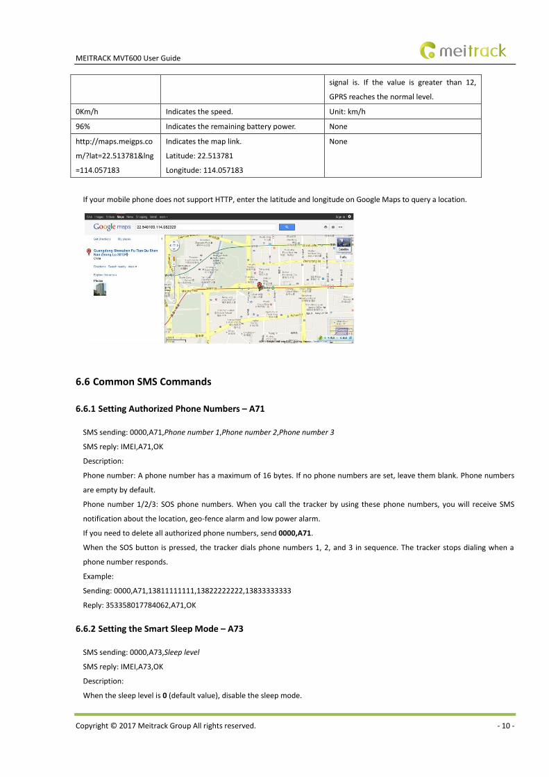
If your mobile phone does not support HTTP, enter the latitude and longitude on Google Maps to query a location.
6.6 Common SMS Commands
6.6.1 Setting Authorized Phone Numbers – A71
SMS sending: 0000,A71,Phone number 1,Phone number 2,Phone number 3
SMS reply: IMEI,A71,OK
Description:
Phone number: A phone number has a maximum of 16 bytes. If no phone numbers are set, leave them blank. Phone numbers
are empty by default.
Phone number 1/2/3: SOS phone numbers. When you call the tracker by using these phone numbers, you will receive SMS
notification about the location, geo-fence alarm and low power alarm.
If you need to delete all authorized phone numbers, send 0000,A71.
When the SOS button is pressed, the tracker dials phone numbers 1, 2, and 3 in sequence. The tracker stops dialing when a
phone number responds.
Example:
Sending: 0000,A71,13811111111,13822222222,13833333333
Reply: 353358017784062,A71,OK
6.6.2 Setting the Smart Sleep Mode – A73
SMS sending: 0000,A73,Sleep level
SMS reply: IMEI,A73,OK
Description:
When the sleep level is 0 (default value), disable the sleep mode.
MEITRACK MVT600 User Guide
Copyright © 2017 Meitrack Group All rights reserved. - 11 -
When the sleep level is 1, the tracker enters the normal sleep mode. The GSM module always works, and the GPS module
occasionally enters the sleep mode. The tracker works 25% longer in the normal sleep mode than that in the normal working
mode. This mode is not recommended for short interval tracking; this will affect the route precision.
When the sleep level is 2, the tracker enters deep sleep mode. If no event (SOS, button changes, incoming calls, SMSs, or
vibration) is triggered after five minutes, the GPS module will stop, and the GSM module will enter sleep mode. Once an event
is triggered, the GPS and GSM modules will be woken up.
Note: In any condition, you can use an SMS command to disable the sleep mode, and then the tracker exits the sleep mode and
returns back to the normal working mode.
Example:
Sending: 0000,A73,2
Reply: 353358017784062,A73,OK
For details about SMS commands, see the MEITRACK SMS Protocol.
Note:
1. The default SMS command password is 0000. You can change the password by using Meitrack Manager and SMS
command.
2. The device can be configured by SMS commands with a correct password. After an authorized phone number is set, only
the authorized phone number can receive the preset SMS event report.
7 Logging In to MS03 Tracking System
Visit http://ms03.trackingmate.com, enter the user name and password, and log in to the MS03. (Purchase the login account
from your provider.)
For more information about how to add a tracker, see the MEITRACK GPS Tracking System MS03 User Guide (chapter 4 "Getting
Started").
The MS03 supports the following functions:
Track by time interval or distance.
Query historical trips.
Set polygonal geo-fences.
Bind driver and vehicle information.
View various reports.
Send commands in batches.
Support OTA updates.
For details, see the MEITRACK GPS Tracking System MS03 User Guide.
8 Installing the MVT600
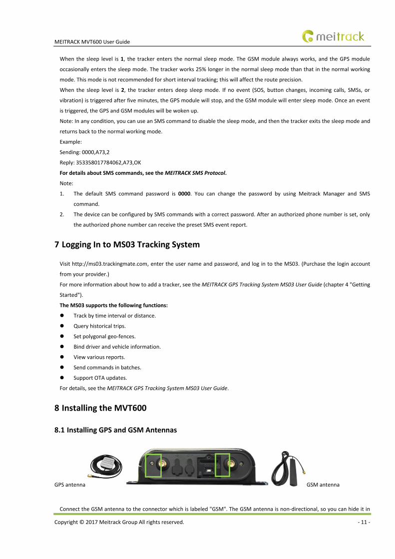
8.1 Installing GPS and GSM Antennas
GPS antenna GSM antenna
Connect the GSM antenna to the connector which is labeled "GSM". The GSM antenna is non-directional, so you can hide it in
MEITRACK MVT600 User Guide
Copyright © 2017 Meitrack Group All rights reserved. - 12 -
any place of a vehicle.
Connect the GPS antenna to the connector which is labeled "GPS". It is recommended that the antenna is facing up to the sky
and the antenna side with words is downwards. Secure the antenna by using double sided tapes.
Note: Do not install the GPS antenna at a metal covered place.
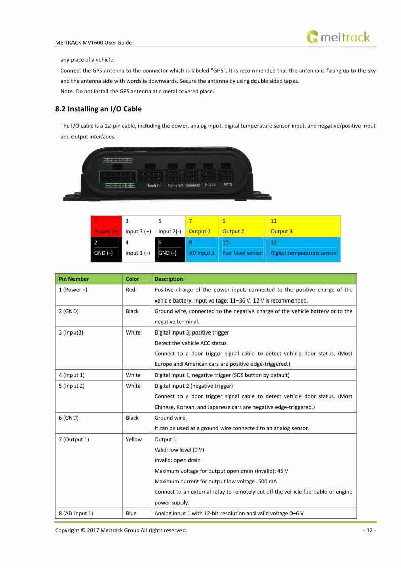
8.2 Installing an I/O Cable
The I/O cable is a 12-pin cable, including the power, analog input, digital temperature sensor input, and negative/positive input
and output interfaces.
1
Power (+)
3
Input 3 (+)
5
Input 2(-)
7
Output 1
9
Output 2
11
Output 3
2
GND (-)
4
Input 1 (-)
6
GND (-)
8
AD Input 1
10
Fuel level sensor
12
Digital temperature sensor
Pin Number Color Description
1 (Power +) Red Positive charge of the power input, connected to the positive charge of the
vehicle battery. Input voltage: 11–36 V. 12 V is recommended.
2 (GND) Black Ground wire, connected to the negative charge of the vehicle battery or to the
negative terminal.
3 (Input3) White Digital input 3, positive trigger
Detect the vehicle ACC status.
Connect to a door trigger signal cable to detect vehicle door status. (Most
Europe and American cars are positive edge-triggered.)
4 (Input 1) White Digital input 1, negative trigger (SOS button by default)
5 (Input 2) White Digital input 2 (negative trigger)
Connect to a door trigger signal cable to detect vehicle door status. (Most
Chinese, Korean, and Japanese cars are negative edge-triggered.)
6 (GND) Black Ground wire
It can be used as a ground wire connected to an analog sensor.
7 (Output 1) Yellow Output 1
Valid: low level (0 V)
Invalid: open drain
Maximum voltage for output open drain (invalid): 45 V
Maximum current for output low voltage: 500 mA
Connect to an external relay to remotely cut off the vehicle fuel cable or engine
power supply.
8 (AD Input 1) Blue Analog input 1 with 12-bit resolution and valid voltage 0–6 V
MEITRACK MVT600 User Guide
Copyright © 2017 Meitrack Group All rights reserved. - 13 -
Connect to an external sensor, such as the fuel level sensor.
9 (Output2) Yellow Output 2
Valid: low level (0 V)
Invalid: open drain
Maximum voltage for output open drain (invalid): 45 V
Maximum current for output low voltage: 500 mA
Connect to an external relay to remotely cut off the vehicle fuel cable or engine
power supply.
10 (Fuel level sensor
input)
Blue Analog input 2 with 12-bit resolution and valid voltage 0–6.6V
The AD cable is equipped with a white plug. It is connected to the A53 fuel level
sensor by default.
11 (Output 3) Yellow Output 3
Valid: low level (0 V)
Invalid: open drain
Maximum voltage for output open drain (invalid): 45 V
Maximum current for output low voltage: 500 mA
Connect to an external relay to remotely cut off the vehicle fuel cable or engine
power supply.
12 (Digital temperature
sensor or iButton input
port)
Blue TTL3.3V level
Connect to the A52 digital temperature sensor or iButton by default by using
the A61 sensor box.
Note: The DC or AC voltage that is greater than 3.3 V is not allowed. Otherwise,
the device may be damaged.
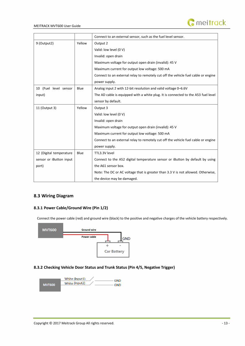
8.3 Wiring Diagram
8.3.1 Power Cable/Ground Wire (Pin 1/2)
Connect the power cable (red) and ground wire (black) to the positive and negative charges of the vehicle battery respectively.
8.3.2 Checking Vehicle Door Status and Trunk Status (Pin 4/5, Negative Trigger)
MEITRACK MVT600 User Guide
Copyright © 2017 Meitrack Group All rights reserved. - 14 -
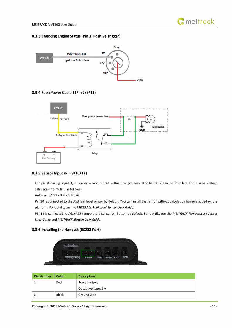
8.3.3 Checking Engine Status (Pin 3, Positive Trigger)
8.3.4 Fuel/Power Cut-off (Pin 7/9/11)
8.3.5 Sensor Input (Pin 8/10/12)
For pin 8 analog input 1, a sensor whose output voltage ranges from 0 V to 6.6 V can be installed. The analog voltage
calculation formula is as follows:
Voltage = (AD 1 x 3.3 x 2)/4096
Pin 10 is connected to the A53 fuel level sensor by default. You can install the sensor without calculation formula added on the
platform. For details, see the MEITRACK Fuel Level Sensor User Guide.
Pin 12 is connected to A61+A52 temperature sensor or iButton by default. For details, see the MEITRACK Temperature Sensor
User Guide and MEITRACK iButton User Guide.
8.3.6 Installing the Handset (RS232 Port)
Pin Number Color Description
1 Red Power output
Output voltage: 5 V
2 Black Ground wire
MEITRACK MVT600 User Guide
Copyright © 2017 Meitrack Group All rights reserved. - 15 -
3 Orange RX, MVT600 receives data from the handset.
4 Yellow TX, MVT600 sends data to the handset.
5 Blue Positive charge of the microphone
6 Green Negative charge of the microphone
7 Purple Positive charge of the speaker
8 White Negative charge of the speaker
Note: The RS232 port supports peripherals, such as the A21 LCD display and LED display. For details about peripheral functions,
see the MEITRACK LCD Display User Guide or MEITRACK LED Display User Guide.
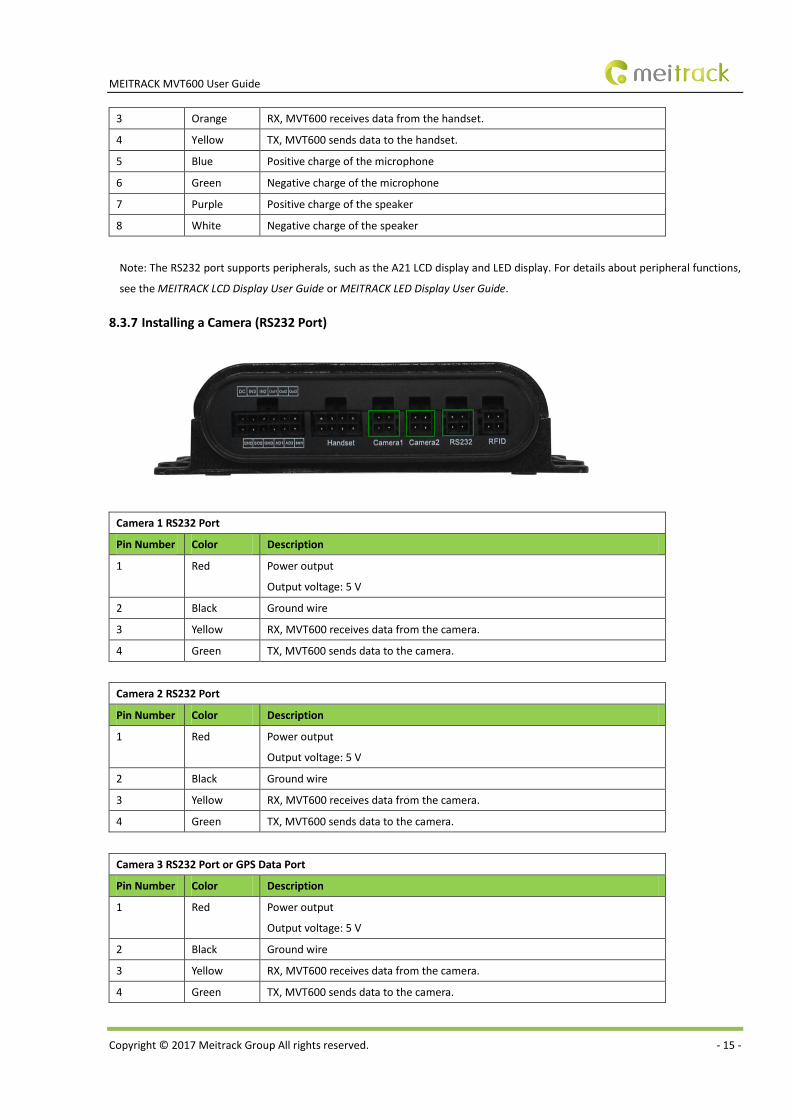
8.3.7 Installing a Camera (RS232 Port)
Camera 1 RS232 Port
Pin Number Color Description
1 Red Power output
Output voltage: 5 V
2 Black Ground wire
3 Yellow RX, MVT600 receives data from the camera.
4 Green TX, MVT600 sends data to the camera.
Camera 2 RS232 Port
Pin Number Color Description
1 Red Power output
Output voltage: 5 V
2 Black Ground wire
3 Yellow RX, MVT600 receives data from the camera.
4 Green TX, MVT600 sends data to the camera.
Camera 3 RS232 Port or GPS Data Port
Pin Number Color Description
1 Red Power output
Output voltage: 5 V
2 Black Ground wire
3 Yellow RX, MVT600 receives data from the camera.
4 Green TX, MVT600 sends data to the camera.
MEITRACK MVT600 User Guide
Copyright © 2017 Meitrack Group All rights reserved. - 16 -
Note: A Micro SD card is required if you have installed a camera. Otherwise, you cannot take photos. For details about how to
install and use the camera, see the Meitrack Camera User Guide.
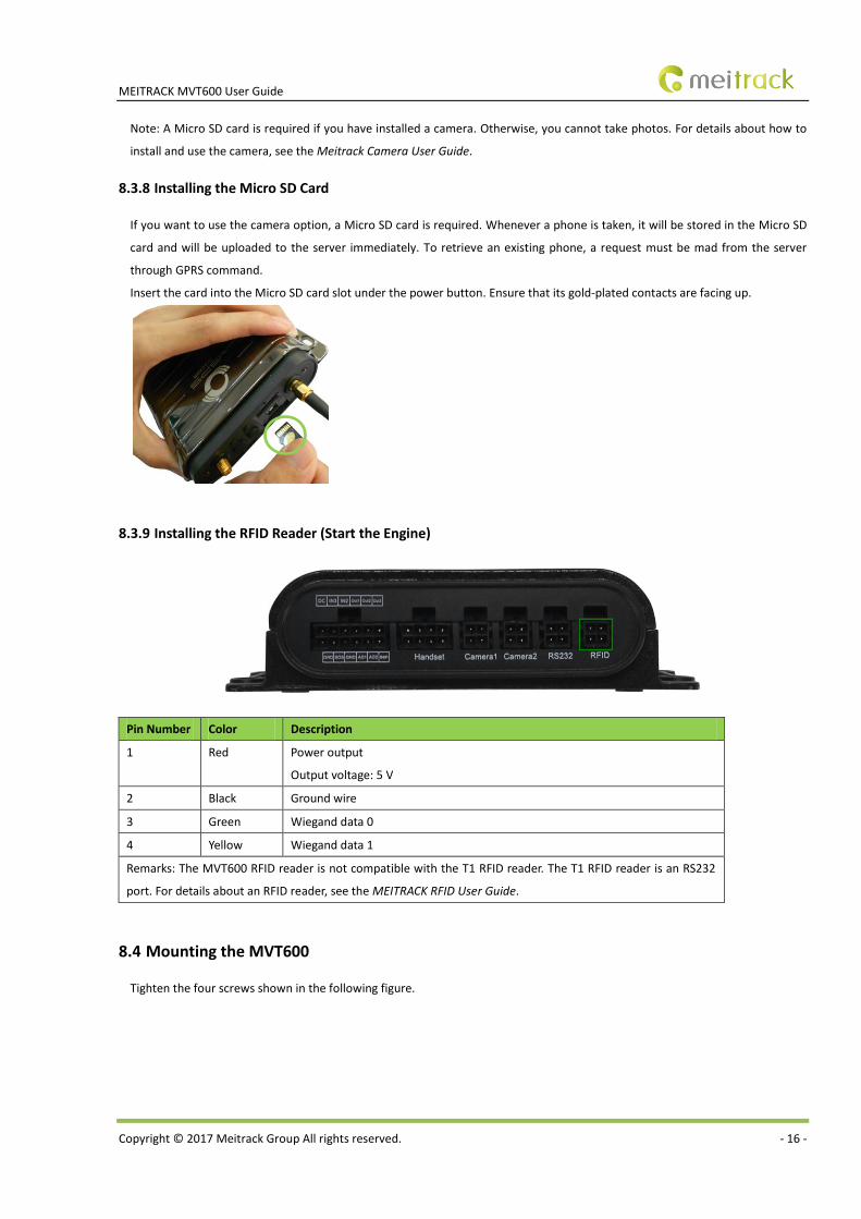
8.3.8 Installing the Micro SD Card
If you want to use the camera option, a Micro SD card is required. Whenever a phone is taken, it will be stored in the Micro SD
card and will be uploaded to the server immediately. To retrieve an existing phone, a request must be mad from the server
through GPRS command.
Insert the card into the Micro SD card slot under the power button. Ensure that its gold-plated contacts are facing up.
8.3.9 Installing the RFID Reader (Start the Engine)
Pin Number Color Description
1 Red Power output
Output voltage: 5 V
2 Black Ground wire
3 Green Wiegand data 0
4 Yellow Wiegand data 1
Remarks: The MVT600 RFID reader is not compatible with the T1 RFID reader. The T1 RFID reader is an RS232
port. For details about an RFID reader, see the MEITRACK RFID User Guide.
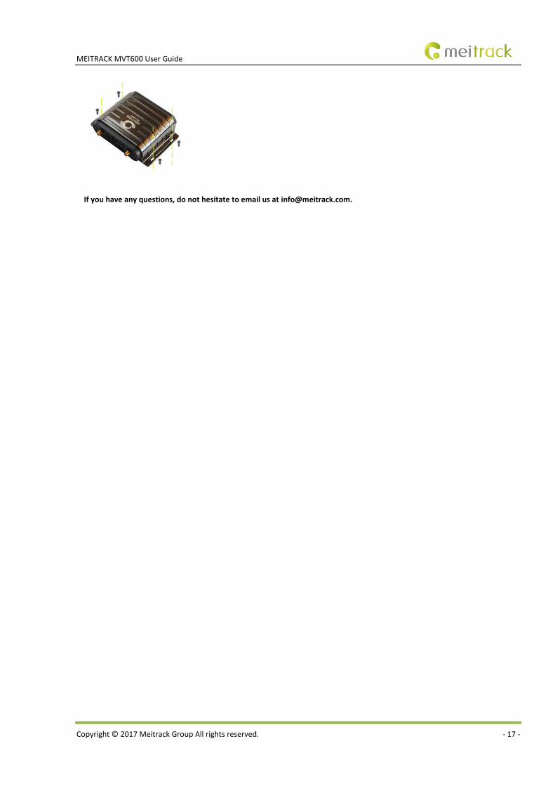
8.4 Mounting the MVT600
Tighten the four screws shown in the following figure.
MEITRACK MVT600 User Guide
Copyright © 2017 Meitrack Group All rights reserved. - 17 -
If you have any questions, do not hesitate to email us at [email protected].