Embed Size (px)
Citation preview

INSTRUCTION MANUAL
MODEL 515 MEGOHM BRIDGE
WARRANTY
We warrant each of our products to be free from defects in material and workmanship. Our obligation under this warranty is to repair or replace any instrument or part thereof which, within a year after shipment, proves defective upon examination. We will pay domestic surface freight costs.
To exercise this warranty, call your local field representative or the Cleveland factory, DDD 216-248-0400. You will be given assist- ance and shipping instructions.
REPAIRS AND RECALIBRATION
Keithley Instruments maintains a complete re- pair service and standards laboratory in Cleve- land, and has an authorized field repair facility in Los Angeles and in all countries outside the United States having Keithley field repre- sentatives.
To insure prompt repair or recalibration serv- ice, please contact your local field representa- tive or the plant directly before returning the instrument.
Estimates for repairs, normal recalibrations, and calibrations traceable to the National Bu- reau of Standards are available upon request.

MODEL 515 MEGOHM BRIDGE CONTENTS
TABLE OF CONTENTS
Section Page
I. INTRODUCTION . . . . . . . . . I-l
II. SPECIFICATIONS . . . . . . . II-1
III. OPERATION. . . . . . . . . . . III-1
A. Outline of Procedure . . . 111-1 B. Description of Controls
and Terminals . . . . . , III-2 C. Operation Steps. . . . . . . III-3 D. Standardization. . . . . . . III-4 E. Connecting the Unknown
Resistor. . . . . : III-4 F. External Bridge Voltage
Supply. . , , . . . . . , III-8 G. Voltage Across Unknown and
Standard Resistors. , , , . III-8 H. Accuracy Considerations. . . III-9
1. Null Detector Sensitivity . . . . . . III-9
2. Null Detector Zero Drift , . . . . . . . . III-10
3. Resolution of the Readout . . . . . ; . . III-10
4. Accuracy of the Read- out and Standard Resistors . . . . . . . III-10
5. Temperature and Voltage Coefficients in the Bridge Resistors. . . . 111-12
6. Leakage Resistance Across the Unknown. . . III-12
Section Page
IV.
8. Time Constants - Slow Response . . . . . III-13
9. Transients Caused by Push-to-Read Switch. III-14
10. Verification of the Accuracy . . . . . III-14
CIRCUIT DESCRIPTION . . . . .
A. power Supply. . . . . B. Null Detector . . . . . C. Bridge Circuitry. . D. Overvoltage Protection. .
V. MAINTENANCE . . .
6. REPLACEABLE PARTS . . . . .
IV-1
IV-1 IV-1 IV-3 IV-4
6-l. Replaceable Parts List. 6-2. How to Order Parts. .
Model 515 Replaceable Parts List . . . .
Model 515 Schematic Diagram 14522D . . .
Green Calibration and Repair Form . . . .
V-l
6-l
6-l 6-l
6-2
6-10
6-11
* Change Notice Last page
*Yellow Change Notice sheet is included only for instrument modifications affect- 7. Errors Caused by Guard
to Ground Resistance. . 111-12 ing the Instruction Manual.
0568R i


SECTION I - INTROlXJClTON
The Model 515 Megohm Bridge if5a Wheatstone Bridge for measuring resistors from 105 ohme to 10 ohms with accuracies from 0.05% to 1.0%. It is complete, with an electrometer null detector, shielded enclosure for the unknown, and a bridge voltage supply.
A unique system of switches is provided to allow corrections to be made for the slow changes in resistance of the standard high megohm resistors. This enables all values of resistance to be read with rated accuracy, directly from the bridge dials.
Bridge voltages in one volt steps up to 10 volts are available from the internal supply. With external supplies, voltages as high as 1,000 volts csn be used.
A connector is provided so that unknown resistors can be measured outside the instrument as well as in the built-in shielded enclosure.

SECTION II - sPFXXF1cATI0NS
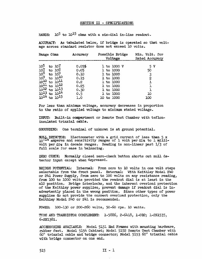
RANGE: lO5 to l&5 ohms with a six-dial in-line readout.
ACCURACY: As tabulated below, if bridge is operated so that volt- age *cross stendard resistor does not exceed 10 volts.
RangeOhms Accuracy Possible Bridge Min. Volt. for Voltage Rated Accuracy
105 to 10-f 0.05% 1tolooOV 5v 10
;I to 108 0.05 1tolocn to 109
50 10 109 to 1010
0.10 1 to loo0 3 1toloco
1010 to loll o.l.5 2 0.2 1 to 1000 1
loll to loI2 0.25 1t0lOo0 1 12 to lo13
El3 to 1014 0.30 1 to 1000
1014 0.5 1to 1000 1;
to lo15 1.0 10 to 1000 100
For less than minimum voltage, accuracy decreases in proportion to the ratio of applied voltage to minimum stated voltage.
INKTT: Built-in compartment or Remote Test Chamber with teflon- insulated triexial cable.
GROUNDING: One terminal of unknown is at ground potential.
yy4DmmR Electrometer with a grid current of less than 5 x amperes and sensitivity ranges of lvolt perdiv. to 1 mill-i-
volt per diw in decade ranges. Reading is non-linear past l/3 of full scale for ease in balancing.
ZERO CREYX Normally closed zero-check button shorts out null de- tector input except when depressed.
BRIWEFQTERTI&z Internal: From zero to 10 volts in one volt steps selectable from the front panel. External: With Keithley Model 2443 or 241Power Supply, from zero to 100 volts on any resistance reading, from 100 to 1000 volts provided the readout dial is at least in the x10 position. Bridge interlocks, and the inherent overload protection of the Keithley power supplies, prevent damage if readout dial is in- advertently placed in the wrong position. Since other types of power supplies do not provide the correct overload protection, only the Keithley Model 240 or 241 is recormnended.
POWER: 100-130 or 200-260 volts, 50-60 cps. 10 watts.
TIJBE AND TRANSIS!t.OR COMPLE!MER? i-5886, 2-6418, 1-0~2; 1-2~1535, 6-21il381.
ACCESSORIES AVAILABLE: Model 5151 End Frames with mounting hardware, rubber feet. Model 5154 Cabinet; Model 5152 Remote Test Chamber with 60" triaxial cable and bridge connector; Model 5153 60" trisxial. cable with bridge connector on one end.
515 II - 1

DIMENSIONB: Model 515 bfegolpn Bridge, 19" w x 14" h x I@" d. Model 5154 Cabinet, 21" w x 25" h x 16&f a.
NE2 WEIGR!J!z Model 515 Megolm Bridge, 24 lbs. Model. 5154 Cap- inet, 52 lbs.
515 II - 2
SECTION III - OPFRATION
A. OUTLINE OF PROCEDURE, (taken from instructions fastened to the inside of the door of the Shielded Measuring Compartment).
1. Connect power cord to 115 volts, 50/60 cps unless specified on rear for 230 volt. To change line voltage see Section V - Maintenance.
2. Turn on power; set MILLIVOI/IS PER DIVISION switch to 1000; release HJSH 'IO READ switch. Set meter to zero with FINE ZERO. If necessary use COARSE ZERO. Increase sensitivity and rebal- ace. Drift which msy be apparent at maxirann sensitivity will become negligible after a short warm-up.
3. STANDARM- Set FUNC'IION switch to STANDARDIZE: MULT- 1PLIERdialtom; and RESISTAEtX, OHMS dials to 10.000. Bring to exact null with ORMS dials; at the same time increase the null detector sensitivity to ma%-. Release HJSH 9 READ button and set FUNCTION switch to CALIBRATE. Adjust l0 CALIBRATE potentiometer to give a null when
T II 9?3 FOND switch is oper-
ated. Next set exponent dial t&IO and repeat step 3. Do the same in sequence UJP thrn I.0 . This completes the bridge standardization.
4. 0PEwJ!I0N: Place resistor to be measured in compartment. Locate the ground clip to suit the resistor length, and close compartment.
Select bridge voltage. Internal voltages from 1 to 10 volts or external voltages up to 100 volts may be used with no special precautions. Above I.00 volts the xl0 or xUl0 dial must not be set at zero. With the Kelthley 240 or 241 Power Sypp3y, the interlock circuit will prevent damage.
Set null detector sensitivity to minimum and operate PUSH M READ button. If miU. detector deflects to left the readout dials (RESISTAECE, OBMS) are set below value of resistance. Increase the indicated mISTAWCE until a null is obtained. If null detector deflects to right reduce the indicated RE- SISTANCE. If no deflection is observed increase null detector sensitivity. Final balance should be made tith enough sensltiv- ity to give required accuracy.
For external operation, attach special cable only to input con- nector and set FUEtX!ION switch to EiilWNU OPEW. Since the door interlock is now inoperative observe care with high bridge voltages.
5. ACCURACY: As tabulated below, if bridge is operated so that voltage acrose stendard resistor &es not exceed 10 volts.
515 III -1

Rang% ohms Accuracy Possible Bridge Min. Volt. for Voltage Rated Accuracy
I.05 I.07
to lo;
108 : $9 I.09 to 1010 lo~tolo~ lo~tolLG lo12 to I.013 lo13 to lo* lo14 to I.015
1tolooov 5v lo to loo0 50 1to lGQ0 3 1 to loo0 2 1 to loo0 1 1tOlOOO
0.36 1 to 1000 ;
0.5 ltolcoo 1.0 lotoKxxl lE
For less then mlnimm voltage, acouracy decreases in proportion to the ratio of applied voltage to minirmpm stated voltage.
B. DEWRIPl!IONOFCONTROU3AND~AIS:
BRIR3EVOUCS: This rotary switch adjusts the voltage applied to the bridge In 1 volt steps up to I.0 volts and &so Is used to energize the external supply circuit when it is in the EK!l! position.
ON: Toggle switch is the main power switch. Preseme of power is indicated by the i-ted meter dial.
MIUXVOIfE3 PER DIVJSIOIk Rotary switch provides decade step6 of nuU detector sensitivity.
FINE ZERO: Ten-turn control18 used for sett%ng the null de- tector to zero.
COARBEZERO: Eleven position rotary switch sets the meter zem ,&thin the range of the FINE ZERO controls. It mey be swltchee8 with a screwdriver from the fxont panel.
NUT& INDICAMR: Three-inch meter, Incorporating a non-linear ;mvement for easy bridge balancing,
'RTSH 9X) READz Push-button switch mxnNJy shorts the miJ.l de- tector @put. It may be locked In the open position.
'FUNCTION Four position rotary stitch provides the necessary circuit arrangements for calibration of the standards, and also employed when the unknown resistor is outslde the instr7.mvd.
'RESIS'JANCE, OHMS: These seven di.als include five decade step xw-itches and one rheostat which forn the variable arm of the bridge. !W seventh dial is a nailtiplier switch. At b&lance, the unknown resistance is read directly from these dials.
Below these dials is the shielded test chamber. This contains the external input connector and 81s calibration controls in addition to the guarded test terminal. The external input con- nector is a teflon insulated triexial receptacle (Gremw 5632~).
515 III - 2
EUSE: A fuse extractor post Is located on the rear of the in- strmnent . For ILL5 volt operation use a 3 AG, t amp. fuse; for 230 volts use a 3 b3, l/8 mqp.
POWER CORD: The three wire cord with the NlNA approved three- prong plug provides a ground connection for the cabinet. An adapter to allow operation from twn prong outlets is provided.
ACCESSORY OUTLET: A three-terminal convenience outlet Is pro- vided on the rear for operation of an external power supply. It is wired directly to the powr cord and is not controlled by the bridge power stitch.
EXTEBNAL INHTl!z UHF receptacle on the rear of the instrument, used to connect an external power sqpply when bridge voltages above 10 volts are desired.
C. OPERATION STEPS
1. Connect power cord to ll5 volt, g/f50 cps, unless specified on resx for 230 volts. !Co change line voltage see Section V, Maintenance.
2. Set null detector to l.CW milklvnlts per cllvislon and un- lock PUSH 'JB READ snitch so null detector input is shorted (note the null detector is normeSLy shorted corresponding to sn open galvanonder key).
3. !Cum power on and allow 30 seconds for warm-up. The meter should indicate zero. Increase mill sensitivity and re-zero if necessary. If the detector cannot be set to zero, use the coarse zero control.
4. Standardize the bridge if necessary (See D - Stsdardiza- z, following).
5. Insert the component to be measured in its test fixture. Set the function switch to OPRRATE when using the self-contained shielded measuring compartment, or set it to EWERNAL OPFJWCE when the unknown is located in the Model 51.52 Ren&e Test Chamber or in another external sample holder. See E. Connecting to the Unknown Resistor, which follows for detailed instructions for connecting the unknown.
6. Set the BRnaE MU16 to the desired value. For external bridge supplies, see F. External. Bridge Voltage Supply following.
7. Operate the FWH M RENI button and b&Lance for null with the resistsnce dials. Increase the null detector sensitivity (See H.Aa?uracy) to give the desired accuracy at final belsxxe. The resistance of the comnent is then read. directly from the resistence dlaJ.8.
Use x M to x O.OOldi
515 III - 3
D. STAEDARDIZ4TION
Wire-wound resistors have the greatest accuracy and keep their cali- brations over long periods of time. Values greater then about one- megohm, however, are too large and too expens e to be widely used. Carbon film resistors provide values up to 10 ei ohms and higher with reasonable SUCC~QS and this type resistor is used in the Model 515. But then value of these resistors changes wlth time, sometimes one or two percent per year.
The Keithley Model 515 Megohm Bridge has been designed so that fre- quent compensations can be made for variations of its high-megohm standard resistors. This process is called Standardization and is carried out as given below. Section IV - Circuit Description dis- cusses the circuitry involved.
The bridge should be restandardized following a chenge in tempera- ture of greater than about lOoF, and at least once each week, to compensate for the errors introduced in the carbon standards by tem- perature and time. For the utmost accuracy possible from the bridge, it can be standardized. daily, hourly, or immediately before a crit- ical measurement.
To Standardize the Bridge:
1. Set the Multi 8
lier OfJim dials) to 10
(the farthest right of the RESISTANCE, .
2. Set TXINCTION switch to STANDARDIZE
3. Set NCLtL DETECTOR to 1000 mv per division.
4. Operate IUSH ltl READ switch and balance the bridge as in normal operation. The reading will be close to 10.00. The final balance should be made with maxinnun null sensitivity.
5. Release BUSH To READ switch and set FUNCTION switch to CWBRATE.
6., Operate PUSH To READ switch and re-balance the bridge with the 10 CALIBRQE potentiometer located in the Shielded Measur- ing Compartment.
7. Turn FUNCTION switch back to STANDARDIZE.
8. Turn multiplier to I.07 and repeat steps 4 thru 7. Do this for each successive mult lier thru 1011. The 1Ou position is ot used since the 10
I.? f?i ohm standard is calibrated in the
lo multiplier position.
E. COIVNKTING TREUEKWOWWR.E3IS'lrOR
1.~ Using Internal Test Chsmber
515 III - 4

Fig. 1 Shielded Measuring Compartment, With Unknown Installed
The bottom section of the bridge contains the shielded compart- ment for holding the unknown resistor, and is accessible when the hinged door has been opened. The compartment has been de- signed for greatest user convenience. Its being shielded elim- bates troublesome pickup, and the unit construction eliminates the necessity for having cables running from the unknown to the bridge, with their associated flexure noise.
The measuring compartment will accept resistors up to about eight inches long. Connections to the bridge are made through banana jacks. A convenient clip to use with the banana jack is the readily available Grayhlll Test Clip #2,1; it has a ban- sna plug on the bottom snd spring clips on the top for holdin@; the resistor heads; three are supplied with each bridge. These clips are illustrated in Fig. 1, holding a typical high-megohm resistor.
A number of ground jacks have been provided so that the ground clip can readily be placed for conveniently holding the unknown resistor, irrespective of its length.
In measuring high resistances, the many precautions necessary in electrometer techniques must be borne in mind; most important are the need for dryness and cleanliness so that leakage resist- ance paths from the HI terminal to ground will not affect the accuracy of measurement, and mounting the resistor so that its body does not touch conductors or other insulators setting up undesired or inadvertent leakage paths.
53.5 III - 5

2. Unknown Resistance Ecternal to ths Bridge.
The Moe1 51.52 Remote Test Chamber shown in Fig. 2 Is used for testing irmilation or making other external shielded measure- ments.: This test chamber is equipped with an integral &I-Inch teflontinsulated trisxial cable fitted with a conuector for attaching to the mating cqnnector in the Shielded Measuring Compar&nentlnthebr.Mge. The chamber and connecting cable are rated for continous operation at temperatures as Wgh as 125w.
Flg. 2.Model 5152 Remote Test Chamber
The eLectrical connections are made throngh banana jacks in the oh&her. The hw.yhilJ. #2-1Test Clips as shown in Fig. 2 are furnished to facilttwte installing unkuowns tith axisJ~lea&s. The banana jacks of course, can be used with any other connectors or resistor holders.
To use:the Model 5152 Remote Test Chamber, fasten its cable connector into the mating connector located in the Measuring Compartment in the Bridge, and connect the unknown resistor betweeq the RI and GROUND banana jacks in the Test Chamber (us- ing the Cks+yhil.l test clips if possibae).
The third bsnsz.% jack in the Renwbe Test Chamber Is QUARD; it Is cdn@ected through the inner shield braid of ths triaxial cable to the guard connection in the Bridge.
Guarding is used exbenslvely in the Bridge to reduce the e&or6 causedfby spurions Le&age cwrents. WaxIing should also be [email protected] in the construction of test electrodes fitted to the RemoteITest Chamber, in order to obtain the greatest accuracy from We bridge measurement,
515 III - 6

The guard conductors are driven from the galvanometer junction of the low tiedance standard arms of the bridge; a total re- sistance less than 10" ohms from guard to gmund till stit the standards sufficiently to create errors great enough to impair the rated accuracy of the bridge. Great care has been taken in the construction of the bridge to kee the GUARD to
Yl GROUND resistance substantial& higher than 10 ohms, and cexe should be taken by the user to maintain that high level.
Fig. 3 is a simplified schematic diagram showin@; the electrical connections of the standard and readout resistors, the unknown, the null detector, and the guarding. A more extensive discus- sion of the circuit operation and guarding will be found in Section IV Circuit Description.
Fig. 3 Model 515 Megohm Bridge, Simplified Schematic Diagram
In cases where measurements with the unknown external to the bridge are necessary and the Model 5152 Remote Test Chambe? is not suitable, the user can make his own holding fixture and connect it to the bridge.
Teflon insulded trisxial cable should be used for the con- nection. The central conductor is the High Impedance conductor; the inner shield braid is the Guard, and is driven from the low impedance arms of the bridge; and the outer braid is GND, to provide shielding. Amphenol 21-529 is a suitable cable.
515 III - 7

The connector should also be teflon insulated. Gremar 7991 is satisfactory. Fig. 4 shows the connector and cable.
F. MTERWAL BRIIGEVOLTAGESUPPLY
Bridge voltages higher than the 10 volts available from the internal
;;r; 4 are desired when measuring resistances greater than about ohms, or in studying the voltage coefficient of a resistor.
A UliF connector labelled EXTERN& LLNFVT is mounted on the rear of the bridge cabinet for ready connection of a high voltage source. The shell of the connector is at ground potential, and this grounds one terminal of the external bridge supp4. The central conductor is the high - voltage lead. The bridge is insulated so that the external bridge voltage can be as high as 1000 volts.
Either the Keithley Model 241 or the 240 Regulated High Voltage Sup- ply makes a very satisfactory source for external bridge voltage. The over-current protection on each is an important feature in pre-
xenting damage to the bridge resistors or to the unknown.
Whenusing externalbridge supply, setBRII?GEVOLTSto EXTafter connecting the supply to the UHF receptacle on the rear panel. Do not app4 more than 100 volts unless the x ICC or the x 10 dial is in a position other than "O", for too much current will flow through the bridge resistors. With the recommended Model 240 or 241 Regulated Voltage Supp4 the over current protection will prevent damage in the eventthis precaution is not observed.
In making voltage coefficient measurements, it should be kept in mind that the voltage applied to a Wheatstone Bridge is greater than the voltage appearing across the unknown resistance being measured. The relationship between the bridge voltage and the voltage across the unknown is given in Section 0, below.
The shielded measuringcompartment in the bridge has a safety switch which is operated when the door is closed. This switch operates a relay whiah applies the voltage from the external bridge supply to the bridge circuit. With the door open, the voltage is renmved, so that the unknown can be changed without possible harm to the operator.
When the unknown is located outside the bridge, and the FUNCTION switch set to MTERNAL OPERATE, this safety interlock is removed fmm the circuit< Unless the external bridge voltage supply is turned off or disconnected, voltages dangerous to the operator may be present at the unknown terminals. A convenient means of disconnecting the source is to switch the BRIDGE VOLTAGE from EXT to zero.
G. MLTAGEAC!RGSSURKD3WNARDSTANBARB
In many cases, particular4 in measuring coefficients of resistors. it is important to know the voltege across the unknown. In measuring
515 III - 8

OY63R
the leakage resistance of capacitors, the applied voltage must be known to avoid breakdown. Also, for rated accuracy, the voltage across the standard resistor must not exceed ten volts.
If the bridge voltage is E, the unknown resistance X, and the stand- ard resistance S, then the voltage across the unknown is:
and the voltage across the standard is:
The bridge voltage is read from the BRImE VOLTS dial or from the external bridge voltage supply. The standard resistance is the value indicated by the m&tiplier dial.
H. ACCUHACYCONSIDEHATIONB
The accuracy of measurement of an unknown resistor in a Wheatstone Bridge depends primarily on the accuracy and stability of the other three arms in the bridge, upon the resolution of the variable arm, and upon the ability of the null detector to respond to the small incremental changes in the variable arm. There are also numerous secondary effects. These will aU be discussed below.
1. Null Detector Sensitivity.
To be able to detect a desired fractional deviation of the un- known, corresponding to the wanted percent accuracy of the measure- ment, the required null detector sensitivity is given by the approximate expression*:
e is the null detector signal in volts x is the incremental pa-t of the unknown resistance E is the Bridge Potential in volts S is the Standard Resistance, in ohms X is the Unknown Resistance, in ohms
For resolutions of O.l$ in the unknown,
x = 0.00l.x
If X and S are approximately equal, and the Bridge Potential is 10 volts,
o.oolx = 0.0015,
e = 0.0025 v0its (2.5 millivolts)
*See Electrical Measurements by F. K. Harris. John Wiley & Sons, N. Y. 19.52 515 III - y

In the case when X is approximately 10 S,
e = .W8 volts (o .8 miuvolts)
The maximum sensitivity of the null detector in the Model 515 Megohm Bridge is one millivolt per meter dial division, and is thus sufficient for the rated accuracy of the bridge. Care should be taken, however, to be certain that the detector sen- sitivity and the bridge potential are great enough end the re- sistance of X end S are sufficiently close to each other to obtain the expected accuracy of measurement.
A check on the sensitivity of the system may be made by unbalanc- ing the bridge readout dials a given percentage and observing the null detector deflection.
2. Null Detector Zero Drift.
Vacuum tube electrometers drift about one to two millivolts per hour, and this rate can be expected in the Null Detector. Obviously, a false balance is indicated if the meter points to zero, indicating balance, when in reality thereare several millivolts at the input.
This error is easily eliminated by adjusting the null detector to zero,whlle the PUSH 7.0 READ button is released, then depres- sing the button end balancing the bridge.
3. Resolution of the Readout.
Using only the readout dials x10 through x.001, full rotation of the x.001 dial is O.l$ of the total setting. The dial can be easily read to one-twentieth of its full rotation, giving a readout resolution of 0.005%. This is ten times the best accuracy specified for any range.
When using all the dials, the readout resolution is very much greater than the maximum accuracy.
4. Accuracy of the Readout Resistors,the Standard Resistors, end the Standard Calibration Controls. (See Fig. 3 for the location of each of them in the Wheatstone Bridge Circuit).
The accuracy of the resistors on the switches controlled by each Readout Dial (RFSISTANCE, OHMS) is:
515 III - 10

Xl00 x.01 X.001 0.5% O%$ 0.1% 1.0%
ma~i.smm accuracy with the bridge is obtained when using the dials xlOthroughx.001. !l!his is because the most accurate readout resistors are used, and also because the unknown re- sistance and the standard resistance are sufficiently close that the null detector has enough sensitivity with bridge Wit- eges less than ten volts (see Section III R. 1).
!Che xl00 dial has only 0.5% resistors associated with it because of the extremely high cost of more act
Y te high
value resistors, and because resistors above 10 ohms are not very stable high accuracy measurements are not warranted.
The resistors on the x.01 end x.001 dials are less accurate because they are not followed by enough diels to give high resolution, and their accuracies are great enough for rated accuracy when using the x1.0 to x.001 dials.
With the MCLTIPLIER dial in either the 105 or 106 position all three aTm6 in the bridge itself are wirewound resistors accurate to .02f&, permitting the unknown to be measured to an accuracy of .05$.
With the MUTEIPL.lRR in the lo7 position, after the Standardiza- tion process, the bridge accuracy is that of the previous re,nge (.05$) plus the error introduced by standardizing, which is conservatively set at .05$.
FoUowing this pattern, the accuracy of the bridge at each suc- cessive step of the lrmltiplier dial is the accuracy of the pre- vious step plus the .05$ standardizing error. It is in this fashion that the accuracies in the specifications up thru 1012 ohms were derived.
FromlO~tto l.014 ohms, enough secondaryl~ffects are present to warrant the 0.5% rating, and above I.0 ohms, the xl00 dial
is used, adding enough further error to bring the overall accuracy rating to l.O$.
The standard resistors used are as follows:
Multiplier
q
3
30 I& ld2
Resistor !Pype
Wire Wound 0 (1 Dezosit,ed Carbon
Sealed,?-Meg II I! II II 11
Accuracy
0.0s 0.0s 1.0 % 1.0 5 2.0 $3 2.0 $
515 III - XL

The Standard Calibration Controls arm is either a wirewound resistor accurate to 0.02$, or deposited carbon resistors in series with trinnaing potentiometers.
5. Temperature and Voltage Coefficient of Bridge Resistors.
The wirewqind resistors employed are free from voltage coefficient. They use one of the lowest temperature coefficient of resistance alloys available, changing 20 parts per million per 'C, or O.OG~$,/~C. They are measured at room temperature, 25oc, end for greatest accuracy, the bridge should be used near this temperature.
The depositedcarbon and Hi-Meg resistors have substantially higher temperatuqe coefficients of resistance than the wire- wound resistors. But if the bridge is allowed to come to its working temperature and standardized, it will have its rated accuracy unless the temperature changes. In this case it should be restandardized.
Deposited carbon and Hi-Meg resistors also exhibit voltage co- efficientof resistance. The'Hi-Meg resistors used in the bridge are spiralled and have about one tenth the voltage coefficient of standard Hi-Meg units. Nevertheless, the voltage across these resistors should not exceed 10 volts for ms.xitmsn accur- acy . Seem Section G. Voltage Across Unknown and Standard Re- sisters .
6. Leakage Resistence Across the Unknown.
lOlo ohms shunting one megohm (I.0 6 ohms) produces a change of 0.015; and 1015 ohms shunting 1012 ohms produces a 0.1% change. With high resistance resistors end high accuracies leakage re- sistance is an important consideration.
The termipals of the Model 515 Megohm Bridge have been carefully made with teflon insulation, and guarding has been employed extensiveily . The major concern of the operator in using the bridge is to keep the insulation clean and dry. The user, how- ever, should be greatly concerned with the bobbin and housing or casing of his unlrnown resistor and with any specielly built holdllng fixture. Paper base bakelite which has been handled and allowed to remain in a humid atmosphere has a surprisingly low resistance. Glass envelopes which have been handled and have finger oil and salt paths between fused-in wire conductors, or simple water vapor paths, also csn have a surprisingly low resistance. E&reme care is necessary to avoid unsuspected errors or: instabilities in measuring high resistances.
7. Errors Caused by Guard to Ground Resistance.
Guarding, as described in Fig. 3 Section III E, is used exten- sively in.the construction of the Model 515 Megohm Bridge to
515 III - l2

reduce errors caused by undesired leakege currents. The Guard conductors are driven from the low impedance side of the Null Detector. Resistance from Guerd to Ground shunts the resistors on the Readout Mel switches and the Standard Calibration con- trols. The Readout Mal resistors of xl0 to x.OClmay be as hlghas10me@ms shunted with 5 x 10 In the buildl shunting error was establish;d for the lowest Guard to Grouud T
of ~~~nt~~~$o~~<C~~f~~.
resistence, and the user should da nothing to lower it.
The Guard &onductors are mstly inside the instrument cabinet but Gusrd is exposed in the connector on the external unknown. Wreme care must be taken at all times, with the instrument cover on or'off, to maintain the cleanliness and dryness of the Guard to Ground insulators.
The Guard conductor is also exposed in the 5152 Remote Test Chamber. If sny resistor-holding electrode is connected to
12 T&M&% 5 5 G uard, it too, must have a resistance greater ohms to ground, for meximum accuracy.
8. Time Constants - Slow Responses
Ten picofarads and ICE ohms have a time constent of I.0 seconds; the wiring capacitances in the bridge end null detector input combined with an unknown of about 1012 ohms produces a time constant of several seconds.
The time constant is apparent in the length of time required for the null detector meter to reach its final position after an ed.justmellt has been made in the bridge.
For maxin~~~ measuring accuracy, the bridge null mnst be care- fully determined, and readings taken only after the null detector meter pointer has stopped moving.
The bridge has been carefully designed to keep the stray capacit- ances as low as possible, so that measurements can be made as rapidly as possible. In measuring resistors greater than lOl2 ohms, the standard resistor is never greater than 1012 ohms, thus the time constant is never longer then several seconds.
Measuring the leakage resistance of capacitors with the Model 515 Megohm Bridge can be a very tedious process, for with good capacitors with very little leakage, the time constants with the bridge impedances c&n be as long as several days. It is recommended that this sort of measurement be done by charging the capacitor to a known voltage and measuring its voltage at known times later with a Keithley electrometer voltmeter.
515 III - 13

9. Transients Caused by Push-to-Read Stitch
Whenever two conductors have been m&zing contact and are.separ- ated, a~ charge appears on the contictors. In the Model 515 Megobm Bridge, this charge transfer is apparent in the null detector meter when the Push-to-Read swltch is operated, re- moving the short circuit across the detector input. It is mxt~noticeable when using the EP 10 ing unknowns of 10” ohm or greater.
ohm multiplier and measur-
The Push-to-Read switch has been very carefully designed and constrnqted to minimd.ze charge transfer, but a few nKU.Llivol.ts are often induced in the bridge circuit by its operation. !Phis is not harmful, but it is necessary to wait each time the switch Is operated, for several time constants during which the voltages come to their steady-state value, and the null- detector meter pointer stops drifting.
10. Verification of Accuracy
In chec 105, F ?
ng the ccuracy of prototype bridges, resistors of 10 , ani 10 ohms were coqpared between the Model 515,
and. a Leeds and Northrup Guarded Wheatstone Bridge, Catalog 4232-B. These measurements were thus traceable to the National Bureau gf Standards, e& were verified with various resistor manufackurers. Agreement was within O.Ol$, which is weld. tithin Model 515 specifications.
Resisttlllce values between 107 and. I.010 ohms were s-ted by a deltzwye Transformation; AIEE !!kansactlons Paper 58-556 gives the details.
Resistance values up to 10U ohms were also measured carefulJy by meas~ing the discbarge times of accurately known capacitors. Above I.+ ohms, stray capacitances Introduced too much error. Both the delta-wye and capacitor discharge measurements were well within the specified accuracy of the ohm range was checked by measuring ten 10 3Y
de1 515. !Che 10” ohm resistors and
,,,,cogy$2hm Y series. Agreement was obtained within to 10 5 ohs, accuracy is assured by the care-
ful. meaqurement of the resistors In the xl00 and xl0 switches in the peadout arm of the bridge.
Ten resistors connected in parallel, measured accurately, and then cowected in series is another method of obtaining high value resistors to great accuracies, end was used extensively in developing the bridge in production tests. This method is described in “ElectrlcalMeasurements” by Harris. See Section H, part 1.
515 III - 14

In the manufacture of each Model 515 Megohm Bridge, each of the bridge resistors is measured and found to be within its rated limits before the bridge is assembled. After assembly, each step on each decade is checked with a precision decade box as the unknown resistor. Following this, Keithley de- veloped standard resistors are used to check each step of the multiplier switch. The internal applied bridge voltage supply and nul.l detector sensitivity and zero drift are also checked.
515 III - 15


CIRCUIT DESCRIPl'ION - SECTION IV
The circuit of the Model 515 Megohm Bridge consists of three major components: the Dower supply, the electrometer null-detector and the Wheatstone Bridge.
A. FowEFl SUPPLY
The power supply consists of a transformer, rectifiers and filters, a transistor regutitor supplying I.2 volts dc, and a transistor con- verter which supplies voltages Isolated from ground to the null- detector. A portion of the I2 volts dc Is used to polarize the bridge.
A detailed description of the power supply is as follows: Drawing 14522-D at the rear of the manual is the complete schematic. Tl is the power transformer operating from the power line. The primary may be connected for either IlO or 220 volts. One secondary is center- tapped and, with diodes r@ and DlO, supplies 18 volts at 250 ma. The other secondary and half-wave rectifier Dll supplies 20 volts at 10 ma. The 18 volts is applied to the collector of $1 and is dropped to I.2 volts through the action of Ql and the associated regulator circuitry.
Q4 and Q5 form a difference amplifier which compares a portion of the I.2 volt output with the reference voltage derived from zener diode Dl4. Q3 and Q2 are used as amplifier and driver for output transistor Ql. D13 is supplied from the 20 volt supply referred to above. This supply is "boot-strapped" on the I2 volt regulated supply to furnish a regulated return point for R2l2, the load resistor for Q3. The circuitry is so designed that any change in load cur- rent, or line voltage is compensated perfectly within the operating range. The regulated I2 volts supplies the transistor inverter, consisting of transistors Q6 and Q7 and transformer T2, and also the ten volt bridge polarizing potential.
Transformer T2 and transistors Q6 and Q7 form a dc inverter operat- ing at approximately 200 cps. The feedback winding to the bases of the transistors provides the oscillator drive. The primary in- ductance of the transformer determines the frequency of oscillation. T2 Is especially well insulated to provide the necessary insulation of guard to ground in the bridge circuit. Since the l2 volt source is exceedingly well regulated, all the secondary voltages are unaf- fected by line voltage variation. Therefore, the operation of the null-detector is not affected by line voltage variations.
B. NULL,Dhl'FZ!tDIC)R:
Fig. 4 is a simplified circuit diagram of the null detector. The component designations are the same as used In the complete schematic. The power supply potentials are represented by batteries for simplicity.
515 Iv -1

RI50 DRIVEN GUARD
LO GUARD
FIG. 4
J
The filaments of Pl, V2 and V3 are in series and supplied with 3.6 volts. This voltage also is used to bias the electrometer tube, Vl. V2 is an amplifier and V3 is the output tube. The output clr- cuit is somewhat unique and operates as follows: The meter will have zero deflection only if there is no potential difference be- tween the plus terminal of B3 and minus terminal of FE. This will occur only if the drop across Rl@+ is equal to the potential of B3. This zero output condition is set by adjusting the screen voltage of Vlwith the fine zero control, ~164, and the coarse zero control, 89. An input signal will cause the plate current of V3 to change,
and. the drop across Rlk.4 will increase or decrease, depending on the polarity of the signal. A current will then flow thru the meter and one of the range resistors on SlO, the sensitivity switch. Since the low impedance side of the input is the minus meter terminal the potential drop across the range resistor will alter the potential of the filament circuit in such a way that the grid-filement potential of Vl will remain nearly constant. The filament is the "Driven Guard" since its instantaneous ac potential is nearly equal to the ac poten- tial of the input signal. All the guarded points of the bridge em- cept Sll are returned to this point. This acts as a driven shield and a considerable increase in response speed is realized in certain cases.
51.9 IV - 2

The simplified bridge circuit is shown in Fig. 5. One ratio arm, A. is the six read-out dials. The other ratio arm, B, is nominally I.cO K ohms for each multiplier rage. With the multiplier set at 105 the standard resistor S and the ratio arm B are both 105 ohm .O 10 2
f~ wirewound units. When the multiplier is set at 106, S Is a ohm ,025 wire wound and B is 105 ohm .02$. With the multiplier
at 107 or higher the standard resistor is a carbon film unit of limited accuracy and B is a 95 K fixed resistor in series with a 10 K rheo- stat. By the standardizing procedure described below B is set to an appropriate value to compensate for error in S and the bridge will be direct reading.
The first step in standardizing is done with the multiplier at 106 and the FUNCTION switch at STANDARDIZE. The basic circuit is then as shown in Fig. 6. The unknown X has been disconnected and the standard resistor for the 107 range is in its place. Balsa bridge with the read-out gi eJ.s will give the value60f the 10 3
ng the stand-
ard as compared to the 10 standard. Since the 10 standard is an accurate wirewound unit the value in cated for the 107 resistor is quite accurate. In Fig. 3 the 10 "i' ohm resistor is assumed to be 5% high and the read-out dials will indicate 10.500.
Leaving the read-out dials set the FUNCTION switch is next set to CALIBRATE. As shown in the simplified schematic of Fig. 7 the standard and unknown resistors are replaced with a network of 1O:l ratio, *ccurate to .Ol Ratio arm B is now B7, the adjustable leg a sociated with the 10
6f q* d"r"d. ohm stan Rebalanc
B f ng the bridge with
a null will be obtained when B is 1.05 X 10 ohms.
This completes the standarization of the 107 ohm standard resistor. After this, when using this resistor as a standard its 5% error is exactly corrected for by B7 being 5% high.
515 IV - 3

To standardize the 10' ohm standard the multiplier is set at 107, the FUNCTION switch is returned to STANDARLWE, and the bridge is again balanoed withgthe read-out dials. The indicated read-ou
ft is
the value of the 10 ohm resistor compared to the corrected 10 ohm standard. Next the RJETION yitch is set to CALIBRAT'g and the bridge is rebalanced with ratio arm B .
Af$3r folio* this procedure in sequence for multiplIer positions 10 thru l0 the bridge is completely standardized and will be direct reading on *Xi ranges.
D. OVEBVOLTAGE PF0TEcTION
The function of V4, 8 gas regulator tube, is to prevent damage to the readout resistors from excessive bridge voltage. It is connected thru auxiliary contacts on the xl00 snd xl0 dials across the bridge voltage. Thus if both dials are at zero the circuit is complete and, if snore than 133 volts is applied to the bridge, the tube will conduct current. With a Keithley Model 240 or 241 Voltage Supply this current W-XL be enough to trip the overload relay and no damage will be done. If an unprotected source is used it is possible that V4 would be ruined and then possibly the readout resistors would overheat from excessive current.
IV - 4

SDTJIONV - MAIRTRNARCE
Very few maintenance problems will arise from ordinary use of the bridge. The components used have adequate safety margins and, since the total power consumption is only 10 watts, very little tempera- ture rise will occur even with continuous operation.
If it becomes apparent that the bridge is not working properly the first step is to check the voltage on the printed circuit boards. Remove the six screws on each side and the two on top and remove the cover. Check the voltages on the main power supply board and null detector board as shown on Drawing 14363-c.
If the difficulty is determined to be in the null detector proper the following procedure will be helpful in isolating the cause:
Short circuit the feedback by jumpering the feedback resistor in use. These resistors are mounted on S-10, MILLIVWIS PER DIVISION. The sensitivity w-ill. now be about 500 microvolts per division and it will be rather difficult to keep the meter on-scale with the ZERO control. However, if it is possible to swing the tube voltages thru the values indicated on 14363-c the stage is working satisfactorily. Start with Vland workthru to V3. Once the defective stage is located check the tube itself and then the associated components. If it is necessary to replace the electrometer tube avoid touching the glass near the lead wires.
Once the bridge is operating a good check on the accuracy may be amde by placing the multiplier at 105 and the IUNCTION switch at STARDARDIZR. A null balance should be obtained with the readout dials at IO.000 f.O5$. If the reading is not within these limits it is recommended that the unit be returned to the factory for re- pairs.
The overvoltage tube, Vk, will ordinarily not carry any current and should last indefinitely. However, if the instrument has been used with a supply lacking adequate overload protection it is possible the tube may be damaged. If this has happened it is likely that other components have been damaged also. Check the resistors in arm A and B of the bridge (RIJJ. thro RI.23 and Rl71 thrn Rlgl).
230 volt operation:
To change the power line voltage to 230 volt remove the two jumpers at the bottom of the main power supply board and connect a single jumper as shown in the circuit schematic, 14522-D. Be sure the line cord is removed from the power when doing this. Replace the 4 ampere yrC: fuse with a l/8 ampere unit.
515 V-l


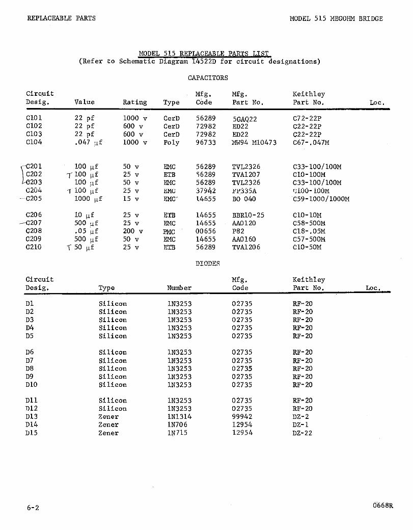
MODEL 515 MEGOHM BRIDGE REPLACEABLE PARTS
SECTION 6. REPLACEABLE PARTS
6-1. REPLACEABLE PARTS LIST. The Replaceable Parts List describes the components of the Model 515. The List gives the circuit designation, the part description, a suggested manufacturer, the manufacturer's part number and the Keithley Part Number. TIE name and address of the manufacturers listed in the "Mfg. Code" column are in Table 2.
6-2. HOW TO ORDER PARTS.
a. For parts orders, include the instrument's model and serial number, the Keithley Part Number, the circuit designation and a description of the part. All structual parts and those parts coded for Keithley manufacture (80164) must be ordered through Keithley Instruments, Inc. or its representative. In ordering a part not listed in the Replaceable Parts List, completely describe the part, its function and its location.
b. Order parts through your nearest Keithley representative or the Sales Service Depart- ment, Keithley Instruments, Inc.
sw
CerD Camp
3Cb
EMC ETB
ampere
Ceramic, Disc Composition
Deposited Carbon
Electrolytic, Metal Case Electrolytic, tubular
M
2,.
0
PMC Poly
I-r
mega (106) milli (10e3) Manufacturer
ohm
Paper, Metal Cased‘ Polystyrene
micro (10-6) E
:Cb
<
LOC.
farad v volt
Glass enclosed carbon w watt
kilo (103) ww Wirewound WWVar Wirewound Variable
Location
TABLE 1. Abbreviations and Symbols.
1065R 6-l
REPLACRABLE PARTS MODEL 515 MEGOHM BRIDGE
MODEL 515 REPLACEABLE PARTS LIST (Refer to Schematic Diagram 14522D for circuit designations)
CAPACITORS
circuit Mfg. Mfg. Keithley Desig. Value Rating TYPO Cbde Part No. Part No. LOC.
Cl01 Cl02 Cl03 Cl04
22 pf 22 pf 22 pf .047 uf
1, C201 203 c202 IlOO vf
100 100 wf
pf C204 7-100 IJ.f
-C205 1000 IJ.f
C206 10 pf -C207 500 pf
C208 .os pf c209 500 pf c210 -i 50 pf
Circuit
1000 v 600 v 600 v 1000 v
50 v 25 v 50 " 25 v 15 v
25 v 25 v 200 " 50 v 25 v
CerD 56289 CerD 72982 CerD 72982 Poly 96733
EMC 56289 ETB 56289 EMC 56289 EMC 37942 EMC. 14655
ETB 14655 EMC 14655 PMC 00656 EMC 14655 ETB 56289
DIODES
5GAQ22 ED22 ED22 MW94 Ml0473
TVL2326~ TVA1207 TVL2326 FP335A BO 040
BBRlO-25 AA0120 P82 AA0160 TVA1206
Mfg.
C72-22P c22-22P c22-22P C67-.047M
C33-lOO/lOOM ClO-100M C33-lOO/lOOM ClOO-100M C59-LOOO/lOOOM
ClO-1OM C58-500M C18-.05M C57-500M ClO-50M
Keithley Desig.
Dl D2 D3 D4 D5
TYPO
Silicon Silicon SiliCOll Silicon Silicon
Number
lN3253 lN3253 lN3253 lN3253 lN3253
Code Part No.
02735 RF- 20 02735 RF-20 02735 RF-20 02735 RF-20 02735 RF-20
LOC.
D6 D7 D8 D9 D10
Dll D12 D13 D14 D15
Silicon Silicon Silicon Silicon Silicon
Silicon SiliCOtl Zener Zener ZC?lll?r
lN3253 02735 lN3253 02735 lN3253 02735 lN3253 02735 lN3253 02735
lN3253 lN3253 lN1314 lN706 1N715
02735 RF-20 02735 RF-20 99942 DZ-2 12954 DZ-1 12954 DZ-22
RF-20 RF-20 RF-20 RF-20 RF-20
6-2 0668R

MODEL 515 MEGOHM BRIDGE REPLACEABLE PARTS
MISCELLANEOUS PARTS
Circuit Desig. Description
Mfg. Keithley Code Part No. LOC.
DSl DS2
Fl (117~) Fuse, .25 amp (Mfg. No. 313, 250) Fl (234~) Fuse, . 125 amp (Mfg. Type HDL)
Jl Guarded Input Terminal (Mfg. No. 6804) 52 Triaxial External Operate Connector (Mfg. No. 5632A) 53 UHF Receptacle, External Volts (Mfg. No. 6804) 54 3-Terminal Accessory Outlet (Mfg. No. 160-2)
Kl
Ml
Pl
Sl
S2
s3
54
s5
~6
Miniature Lamp, 6.3 v at 0.2 amp (Mfg. No. 51) Miniature Lamp, 6.3 v at 0.2 a&p (Mfg. No. 51)
Relay, DPDT
3-Wire Power Cord, 6 feet (Mfg. No. 4638-13)
Rotary Switch, less components, FUNCTION, 4-position Rotary Switch, with components, Function Switch Knob Assembly, Function Switch
Rotary Switch, less components, RANGE, 8-position Rotary Switch, with components, Range Switch
Rotary Switch, less components, BRIDGE VOLTS, 120- position
Rotary Switch, with components, Bridge Volts Switch
Rotary Switch, less components, DECADE Xl00 Rotary Switch, with components, Decade Xl00 Switch Knob Assembly, Decade Xl00 Switch
Rotary Switch, less components, DECADE X10 Rotary Switch, with components, Decade X10 Switch Knob Assembly, Decade X10 Switch
Rotary Switch, less components, DECADE Xl Rotary Switch, with components, Decade Xl Switch Knob Assembly, Decade Xl Switch
08804 PL-8 08804 PL-8
75915 FU-17 75915 FU-20
91737 ~~-64 91737 CS-67 91737 CS-64 02660 cs-66
80164 RL-12
80164 ME-34
82879 co-2
80164 SW-87 80164 22118~ 80164 16323A
80164 SW-80 80164 22116~
80164 SW-91 80164 22113B
80164 SW-123 80164 22120B 80164 14829A
80164 SW-123 80164 22112B 80164 14829A
80164 SW-122 80164 22117B 80164 14829A
0668R 6-3

REPLACEABLE PARTS MODEL 515 MEGOHM BRIDGE
MISCELLANEOUS PARTS Cont'd.
Circuit Desig. Description
Mfg. Keithley Code Part No. LOC.~
s7
58
s9
510
511
512
513
---
Tl Power Supply Transformer T2 Inverter Transformer
Rotary Switch, less components, DECADE X0.1 80164 SW-122 Rotary Switch, with components, Decade X0.1 Switch 80164 221!4~ Knob Assembly, Decade X0.1 Switch 80164 148298
Rotary Switch, Less components, DECADE X.01 80164 SW-122 Rotary Switch, with components, Decade X.01 Switch 80164 22115~ Knob Assembly, Decade X.01 Switch 80164 14829A
Rotary Switch, less components, COARSE ZERO, 11-position 80164 SW-88 Rotary Switch, with components, Coarse Zero Switch 80164 22111B
Rotary Switch, less components, SENSITIVITY, 4-position 80164 SW-92 Rotary Switch, with components, Sensitivity Switch 80164 22119B
Zero Switch Special Push Button 80164
Toggle Switch, on-off S.P.S.T. 80164
Door safety switch 80164
FINE ZERO Control Knob Assembly 80164
80164 TR-39 80164 TR-40
14377A
SW-4
SW-94
148388
RESISTORS
circuit Mfg. Mfg. Keithley Desig. Value Rating Type Code Part No. Part No. Lot .
RlOl R102 R103 R104 RL05
10 kfi .02%, l/2 w w 80164 (1) 100 k0 .02%, l/2 w w 80164 (1) 100 kn .02%, l/2 w w 15909 1252 R47-100K 1 M.O .02%, L/2 w W 15909 1252 R47-1M LO MO I%, L/2 w DCb 00327 NLLA RLZ-L0M
R106 R107 RL08 R109 RflO
100 MO 1%. l/2 w DCb 91637 DC-2 R14-100M 109 a GCb 80164 --- 20658A 1010 R GCb 80164 --- 20659A
;;:: R GCb 80164 --- 20660A
f-l GCb 80164 --- 20661A
RLll 100 kc2 .02%, L/2 w W 15909 1252 R47-LOOK R112 94.5 kil L%, l/2 w DCb 00327 NllA R12-94.5K R113 94.5 kcl L%, l/2 w DCb 00327 NllA R12-94.5K R114 94.5 kn l%, 112 w DCb 00327 NllA R12-94.5K R115- 94.5 kR l%, 1,'2 w DCb 00327 NlLA R12-94.5K
(1) RlOl and R102 are a matched set, Keithley Part Number 13992A
6-4

MODEL 515 l.fEGOHM BRIDGE REPLACEABLE PARTS
RESISTORS Cont'd.
Circuit Mfg. Mfg. Keithley Desig. Value Rating Type Code Part No. Part No. LOC.
Rll6 R117 Rllt? Rl19 R120
R121 R122 R123 ~124 R125
R126 R127 R128 R129 R130
R131 R132 R133 R134 R135
R136 R137 R138 R139 R140
R141 R142 R143 R144 R145
R146 R147 R148 R149 R150
R151 R152 R153 R154 R155
R156
0668R
94.5 kn 94.5 kQ 10 k.Q 10 kQ 10 kR
10 kR 10 kn 10 kfi 100 a 100 sz
100 n 100 R 100 R 100 n 100 a
100 R 100 n 100 n 1 MO 3.3 Ma
3.3 MXl 10 Ma 3.3 Mfi 100 kR 100 kQ
8.2 Ma 22 MQ 4.7 k0 220 kQ 10 k0
5 kQ Not Used Not Used 420 i2 4.3 k0
40 kR 390 k0 1.4 kn 2 kO 1 kR
4 kQ
l%, l/2 w l%, l/2 w lO%, 2 w lo%, 2 w lO%, 2 w
lO%, 2 w lO%, 2 w lO%, 2 ,w I%, l/2 w l%, l/2 w
1%; l/2 w l%, l/2 w l%, l/2 w l%, l/2 w l%, l/2 w
l%, l/2 w l%, l/2 w I%, l/2 w lo%, l/2 w l%, 112 w
I%, 112 w I%, l/2 w lO%, l/2 w lO%, l/2 w lO%, l/2 w
'IO%, l/2 w lO%, l/2 w lO%, l/2 w I%, 112 w lO%, l/2 w
I%, l/2 w
l%, 112 w l%, l/2 w
l%, l/2 w l%, l/2 w l%, l/2 w I%, l/2 w l%, l/2 w
I%, l/2 w
DCb DCb ww ww ww
ww ww ww DCb DCb
DCb DCb DCb DCb DCb
DCb DCb DCb
DCb’
DCb DCb Comp Comp Comp
camp DCb Comp
DCb
DCb DCb
DCb DCb DCb DCb DCb
DCb
00327 NllA 00327 NllA 12697 43-10K 12697 43-10K 12697 43-10K
12697 43-1OK 12697 43-1OK 12697 43-10K 00327 NllA 00327 NllA
00327 NllA 00327 NllA 00327 NllA 00327 NllA 00327 NllA
00327 NllA 00327 NllA 00327 NllA 01121 EB 00327 NllA
00327 NllA 00327 NllA 01121 EB 01121 EB 01121 EB
01121 EB 01121 EB 01121 EB 00327 NllA 01121 EB
00327 NllA
00327 NllA 00327 NllA
00327 NllA 00327 NllA 00327 NllA 00327 NllA 00327 NllA
00327 NllA
Rl2-94.5K R12-94.5K RP27-10K RP27-10K RP27-10K
RP27-10K RP27-10K RP27-10K R12-100 R12-100
R12-100 R12-100 R12-100 RL2-100 R12-100
R12-100 R12-100 R12-100 Rl-1M R12-3.3M
Rl2-3.3M Rl2-~1OM Rl-3.3M Rl-100K Rl-100K
Rl-8.2M Rl-22M Rl-4.7K Rl2-220K Rl-1OK
Rl2-5K
R12-420 R12-4.3K
Rl2-40K Rl2-390K Rl2-1.4 R12-2K R12-1K
R12-4K
6-5

MODEL 515 MEGOHM BRIDGE REPLACEABLE PARTS
RESISTORS (Cont'd)
Circuit Mfg. Mfg. Keithley Desig. Value Rating Type Code Part No. Part No. LOC.
RL57 ~158 R159 Rl60
R161 ~162 ~163 ~164 R165
R166 ~167 R168 ~169 R170
R171 R172 R173 R174 R175
R176 R177 R178 R179 R180
R181 R182 R183 R184 ~185
Rl86 R187 R188 R189
R201 R202 R203 ~204 R205
R206 R207
6-6
4 kcl 2 kQ 1 k0 4 kfl
4 kS1 Not Used 10 kQ 10 kn 1 kQ
Not Used Not Used Not Used Not Used 10 kfl
2 kfi 4 kQ 4 kQ 10 kfl 20 kfl
40 kQ 40 kQ 100 ka 200 kfi 400 k0
400 kR 1 Ma 2 MR 4 Mn 4 MO
10 Ma 20 MCl 40 MO 40 Mel
68 R '200 a 500 cl 500 n 200 0
1.5 kQ 8.2 kn
I%, LIZ w l%, 112 w l%, 112 w l%, l/2 w
I%, l/2 w
lO%, l/2 w 3%, 5 w 3%-l%, 3 w
O.l%, l/2 w
O.l%, l/2 w O.l%, l/2 w O.l%, l/2 w .02%, l/2 w .02%, l/2 w
.02%, l/2 w
.02%, l/2 w
.02%, l/2 w-
.02%, l/2 w
.02%, l/2 w
.02%, l/2 w
.02%, l/2 w
.02%, l/2 w
.02%, l/2 w
.02%, l/2 w
l/2%, 2 w l/2%, 2 w l/2%, 2 w l/2%, 2 w
lO%, l/2 w l%, l/2 w l%, l/2 w l%, l/2 w lO%, 2 w
lo%, l/2 w lO%, l/2 w
DCb DCb DCb DCb
00327 NLLA 00327 NllA' 00327 NllA 00327 NllA
DCb 00327 NllA
Comp 01121 WWVar 73138 ww 12697
EB Rl-1OK A RP4-1OK CM27520NP RP25-1K
ww 15909 1252
ww 15909 1252 ww 15909 1252 ww 15909 1252 ww 15909 1252 ww 15909 1252
ww 15909 1252 ww 15909 1252 ww 15909 1252 ww 15909 1252 ww 15909 1252
ww 15909 1252 ww 15909 1252 ww 15909 1252 ww 15909 1252 ww 15909 1252
DCb DCb DCb DCb
03888 PT-200 03888 PT-200 03888 PT-200 03888 PT-200
camp DCb DCb DCb ww
01121 EB 00327 NllA 00327 NllA 00327 NllA 71450 R252-200
camp camp
01121 EB 01121 EB
RlZ-4K R12-2K R12-1K RL2-4K
R12-4K
R70-10K
R70-2K R70-4K R70-4K R47-1OK R47-20K
R47-40K R47-40K R47-100K R47-200K R47-400K
R47-400K R47-1M R47-2M R47-4M R47-4M
R52-10M R52-20M R52-40M R52-40M
Rl-68 Rl2-200 R12-500 R12-500 RP22-200
Rl-1.5K Rl-8.2K
0568R

MODEL 515 MEGOHM BRIDGE REPLACEABLE PARTS
RESISTORS (Cont'd)
Circuit Mfg. Mfg. Keithley Desig. Value Rating Type Code Part No. Part No. Lot.
R208 R209 R210
R211 R212 R213 ~214 R215
R216 R217 ~218 R219 R220
R221
Circuit
1 kQ 680 R 820 n
390 cl 27 ka 10 kQ 3.3 MR 10 n
10 n 100 n 10 s2 22 ka 470 R
*
lo%, l/2 w lO%, l/2 w lO%, l/2 w
lO%, l/2 w lO%, l/2 w lO%, l/2 w lO%, l/2 w lO%, l/2 w
lO%, l/2 w lO%, l/2 w lO%, l/2 w lo%, l/2 w lO%, l/2 w
l%, 112 w
Comp 01121 camp 01121 camp 01121
Comp 01121 camp 01121 camp 01121 camp 01121 Comp 01121
Comp 01121 camp 01121 camp 01121 camp 01121 Comp 01121
DCb 00327
TRANSISTORS
Mfg.
EB Rl-1K EB Rl-680 EB Rl-820
EB Rl-390 EB Rl-27K~ EB Rl-1OK EB Rl-3.3M EB Rl-10
EB Rl-10 EB Rl-100 EB Rl-10 EB Rl-22K EB R1-470
NllA R12-$<
Keithley Desig.
QL 42 93 Q4 Q5
Q6 Q7
Number Code Part No.
2Nl535 04713 TG-7 2Nl381 01295 TG-8 2~1381 01295 TG-8 2~1381 01295 TG-8 2Nl381 01295 TG-8
2Nl375 01295 TG-15 2Nl375 01295 TG-15
LOG.
VACUUM TUBES
Circuit Desig.
Vl v2 v3 v4
Mfg. Keithley Number ,&de Part No. Lot.
5886 80164 EV-5886-2X 6418 or 592 80164 EV-CK6418 or EV-CK592-4 6418 or 592 80164 EV-CK6418 or EV-CK59&4 OB2 86684 EV-OB2
* Nominal value, factory set.
1269R 6-7

REPLACEABLE PARTS MODEL 515 MEGOHM BRIDGE
00327 Welwyn International, Inc. Cleveland, Ohio
56289 Sprague Electric Co. North Adams, Mass.
00656 Aerovox Corp. New Bedford, Mass.
63060 Victoreen Instrument Co. Cleveland, Ohio
01121 Allen-Bradley Corp. Milwaukee, Wis.
71450 CTS Corp. Elkhart, Ind.
41295 Texas Instruments, Inc. Semiconductor-Components Division Dallas, Tex.
02660 Amphenol-Borg Electronics Corp. Broadview, Chicago, Illinois
72982 Erie Technological Products, Inc. Erie, Pa.
73138 Helipot Div. of Beckman Instruments, Inc. Fullerton, Calif.
02735 Radio Corp. of America Commercial Receiving Tube and Semiconductor Division Somerville, N.J.
75915 Littelfuse, Inc. Des Plaines, 111.
80164 Keithley Instruments, 1nc. Cleveland, Ohio
03888 Pyrofilm Resistor Co., Inc. C.edar Knolls, N.J.
04713 Motorola, Inc. Semiconductor Products Division Phoenix, Airzona
81453 Raytheon Co. Industrial Components Div. Industrial Tube Operation Newton, Mass.
08804 Lamp Metals .and Components Department, G.E. Co. Cleveland, Ohio
12697 Clarostat Mfg. Co., Inc. Dover, N.H.
82879 Royal Electric Corp. Pawtucket, R.I.
86684 Radio Corp,of America Electronic Components and Devices Harrison, N.J.
12954 Dickson Electronics Corp. Scottsdale, Ariz.
91637 Dale Electronics, Inc. Columbus, Nebr.
14655 Cornell-Dubilier Electric Corp. Newark, N.J.
91737 Gremar Mfg. Co., Inc. Wakefield, Mass.
15909 Dawn Division Thomas A. Edison Industries,, McGraw Edison Co., Livingston, N.J.
94145 Raytheon Co. Semiconductor Div. California Street Plant Newton, Mass.
37942 Mallory, P. R., and Co., Inc. Indianapolis, Ind.
96733 San Fernando Electric Mfg. Co. San Fernando, Calif.
99942 Hoffman Electronics Corp. Semiconductor Division El Monte, Calif.
ABLE 2. Code List of Suggested Manufacturers. (Based on Federal Supply Code for Manufacturers, Cataloging Handbook H4-1.)
6-8 0668R

v3
j’ 6418/ v2
P 6418~ i !


For
.REPAIR AND CALIBRATION FORM
repair or calibration, please fill out this form Sales Service Department Keithley Instruments, Inc. 2877.5 Aurora Road Cleveland, Ohio 44139
and return it with your instrument to:
R- Do not write in this space.
user’s Name company Division Data
Telephone Address City Model No.
Ext.
state Zip Serial No.
1.
3.
4.
5.
6.
7.
Reason for Return 2. Calibration Report Desired 0 Repair and Recalibration 0 Report of Calibration Certified 0 Recalibration only (No report, except Traceable to N.B.S. as specified in item 4 on reverse)* 0 Calibration Report *If repairs are necessary to meet speci-
fications, they will be in addition to a Certificate of Compliance 0 Node
the calibration. (for details, sea reverse side of this form)
To help repair the instrument, briefly describe the problem:
1s the problem -Constant 1 Intermittant Under what conditions does the problem occur: =) Control setting e) Line voltage
f) Other (such as line transients, line variations, etc.)
b) Approx. Temperature OF c) Approx. Temperature variation * OF d) Approx. Humidity (high, medium, low)
b) Approx. c) Approx. Temperature d) Approx. Humidity (hrgn, n
Please draw a block diagram of the system using the Keithley. List any other perti- nent data which can help in the repair. Include charts or other data if available.
Signal Source Source Impedance Readout Device:
aRecorder 0 Oscilloscope - Other a None
Lengths & Types of Connecting Cables
What repairs or modifications have been made on this instrument which are not on file with the Keithley Repair Department?
Please enclose any other pertinent data and charI.? which you feel might help the Repair and Calibration Department
Signature Title
1267
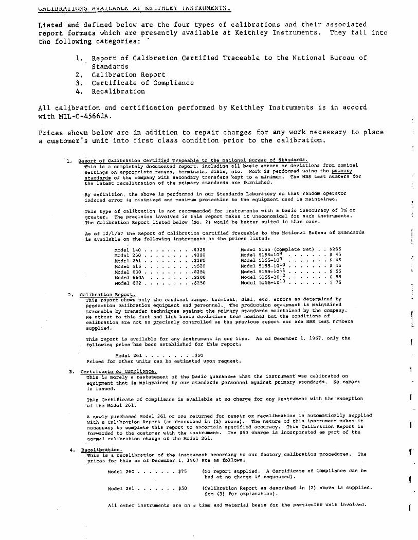
Listed and defined below are the four types of calibrations and their associated report formats which are presently available at Keithley Instruments. They fall into the following categories: .
1. Report of Calibration Certified Traceable to the National Bureau of Standards
2. Calibration Report 3.~ Certificate of Compliance 4. Recalibration
ALL calibration and certification performed by Keithley Instruments is in accord with MIL-C-45662A.
Prices shown below are in addition to repair charges for any work necessary to place a customer’s unit into first class condition prior to the calibration.
I

U.S.A. and Canada sales offices
european services Keithley has a manufacturing facility in Germany and a warehouse and office in Switzerland to provide prompt delivery in the European area. The facilities. staffed by Keithley field engineering personnel. give on-the-spot assistance to your Keithley representative so that he may better serve you. A list of the worldwide Keithley rspresent- atives is given on the back.
K EITHLEY INSTRUMENTS; INC.
28775 AURORA ROAD - CLEVELAND,;OHIO 44139
TELEPHONE: (216) 248-0400
TELEX: 98.5469

international sales offices
NETHERLANDS
PAKISTAN
REPUBLIC OF SOUTH AFRICA Protea Physical 8. Nuclear I”str”nls”tati0”. my. Ltd. P.O. BOX 1793 iahannesburg. T.V.L. Telephone: 838.8351
SPAIN Atab ,ngeniera* Fmique Larreta. 12 Madrid 16 Telephone: 235.3543
SWEDEN cmO”iX AB Jamtlandgatan 125 pa Valuingby Stockholm Telephooe: 87.03.30
SWITZERLAND Ssyffer and Company. 1°C. Bade”erltra9.8 265 CH-8040 Zurich Tslephane: (05,) 7554.11
TURKEY Mevag Karatmy Bankalar Caddesi 71.73 Istmb”, Te,ephone: 49.83.00
YUGOSLAVIA
KEITHLEY INSTRUMENTS, S.A. 14. AVENUE VILLARDIN * CH-1009 PULLY, SUlSSi
TELEPHONE: (021) 28-11-68


![Barley Genomics: An Overviewdownloads.hindawi.com/archive/2008/486258.pdfemployed in cereal genomics have been reviewed [3–8]. In this overview, we have tried to summarize progress](https://img.pdfslide.us/doc/110x75/60a03b83d3bffc34c277fcd7/barley-genomics-an-employed-in-cereal-genomics-have-been-reviewed-3a8-in-this.jpg)


![Untitled1 [njarc.org]njarc.org/manuals/Tech-Master_630_conversion.pdfR3 3.3 1 watt DIAGRAM A R4 1 Megohm, 1 watt Cl .05 mfd., 600 volts CZ 500 mmfd., 10,000 volts Indicates parts added](https://img.pdfslide.us/doc/110x75/5f5a64508d20af3bc2346231/untitled1-njarcorgnjarcorgmanualstech-master630-r3-33-1-watt-diagram-a.jpg)

