Embed Size (px)
Citation preview
OPERA liNG INSTRUCTIONS
for
TYPE 544-8
MEGOHM BRIDGE Form 458-1
February, 1954
GENERAL RADIO COMPANY CAMBRIDGE 39 MASSACHUSETTS
NEW YOitK CHICAGO LOS ANGElE S
U . S . A .

View of the
Type 544-B
Megohm Bridge
With Cover Raised
To Show Panel
SPECIFICATIONS
Range: 0.1 megohm to 1,000,000 megohms, coYered by a dial and a 5-posltlon multiplier switch. A resistance d 1,000,000 megohms can be distinguished from Infinity. Ac1;uracy: +3% on the 0.1, 1, and 10 multipliers; •4 on the 100 and 1000 multiplier:<. Above lo,ooo megohms , the accuracy Is essentially that with which the scale on the MEG~S d1a.l can be read. Tennlnal: AU hlgh..,.olt.age terminals are lnsu· ~a prQiect!on to the operator. A m~mum of 12 rna can be drawn on short clrcu1t. Power Supply: Two types of power s upply are avalbble: (I) an a-c unit delivering d · c test voltages d 500 volts and 100 volts to the bridge, and (2) a battery power s upply of 90 volts . The a-c unit o perates !rom a 105- to 125- volt (or 210- to 250-volt), 40- to 60-cycle line." The batter y power supply consists of 2 No. 6 Dry Cells and 3 Standard 45-volt batteries. This s upplies 45 volts for the tube anode a.nd 90 volts for the test voltage . Power Input: 60 walls at 115 1'0ita, 60 cycles ; with battery supply, approximate current requlremenls are 60 ma lor cathode heaters :and
7.5 ma for anode. Elrterna.l Bridge Vol!:§e: Terminals are pro-1'1ded so that the bridge •ollaie can be obtained from an elrternal source U desired. Up to 500 •olts can be applied. Vacuum Tubes: With battery power supply, a ID!H;P detector tube Is used; the 500-'l'tllt power s upply ll!lell a 6K7.C detector, a 6X4.(; rectlller, a 5U4.(; rectl!ler, and, In the YOlt.age rt!glllators, a 6J5-G, a 8K6-G, a (AI Ballast Tube, :and two Type 2LAG-949 neon lamps. All tubes are supplied. Accesi!Ot les ~wiled: With a -e power supply, a seYen-foot line-connector cord and spare fus es, test probe mounted In co•er and spare neon ballast tube. Batteries are supplied with the battery-operated model. Mounting: Shielded oak cabinet with co•er. Dimensions: Cabinet with C01'er closed, (width) 8·1/2 x (length) 22 - I/2 x (height) 8 Inches, OYer-all. Net Weight: With battery power supply, 29-I/2 pounds; With a-e power supply, 26-3/8 pounds; Type 544-PIO, 14-1/ 4 pounds; Type 544 -P3, 11 - 1/ 8 pounds.
OPERATING INSTRUCTIONS.
for
TYPE 544 .. 8
MEGOHM BRIDGE
SECTION 1.0 PURPOSE
The Type 544-B Megohm Bridge is a direct-current Wheatstone bridge for measuring high resistances. Adequate sensitivity for indicating the bridge balance is obtained from the use of a vacuum -tube voltmeter. Its controls are direct-reading in megohms.
1.1 RANGE AND ACCURACY
The range of the bridge extends from 0.1 megohm to 1 megamegohm with errors varying from 3% upward. Using the main decade of the MEGOHMS dial, which is approximately logarithmic, the accuracy is 3% for the first three multiplier steps up to 100 Mn and 4% to 10,000 Mfl. Above 10,000 Mfl the error increases rapidly, b.ecoming 30% at 100,000 Mfl. A resistance of 1 MMfl (1 ,000,000 megohm s) can be detected.
SECTION 2.0 INSTALLATION
2.1 ACCESSORIES SUPPLIED
A flexible jack with lead is mounted in the cover for checking lhe internal standards as explained in Section 4.0, Paragraph 4.4.
2.2 POWER SUPPLIES
The Type 544-B Megohm Bridge can be operated e ither from dry batteries or from an a-c power supply, Type 544-P3. These power supplies are interchangeable and fit into the compartment at the rear of the cabinet. One of these power supplies is normally supplied with the bridge, properly mounted in the rear compartment, except that the tubes are protected. The detector tube for the bridge Is considered to be a part of the power s upply , because dUferent tubes are required for battery or a-c ope ration. This tube Is not plugged into its s ocket and will be found inside the rear compartment.

2.3 TYPE 544-P3 500-VOLT A-C POWER SUPPLY
2.31 Tubes and Accessories :
1 - Type 6X5G Rectuier Tube 2 - Type T-4-1/2 Ballast Tubes 1 - Type 5U4G RectUier Tube 1 - Type 4A 1 Ballast Tube 1 - Type 6K6G Regulator Tube 1 - Type 6K7G Detector Tube 1 - Type 6J5G Regulator Tube 1 - 200 n Galvanometer Shunt
1 • Attachment Cord
2.32 ~~I}Dect!ons_: Remove u.e cover of the power supply compartment and also remove the bridge from its compartment. Remove the protecting cartons from the five tubes in the power supply and see that they are seated in their sockets. Check the seating of the fuses. See that the s horting links that determine the voltage applied to the bridge (500 v or 100 v) are set for the desire<i voltage as described in Section 5.0, Paragraph 5.4.
Plug the Type 6K7G Detector Tube into lts socket below the panel. See that the 200!2 shunt Is connected across the galvanometer terminals. Reconnect the Jones plug between power supply and bridge. Replace panel and cover and connect attachment cord.
2.4 TYPE 544 - PlO BATTERY POWER SUPPLY
2.41 Tubes and Accessories:
1 - Type ID5G Detector Tube 2 • No. 6 Dry Cells 3 - 45 v Dry Batteries 1 - Battery Connector
1 - 2-kn Resistor to be used as a Battery Connector
1 - Wooden Battery -Separator 1 - Battery Cable with Jones Socket
2.42 Connections: Remove the cover of the power supply compartment and al so remove the bridge from its compartment. Check the arrangement and wiring of the batteries as shown in the battery diagram and cable color code of Figures 1 and 9. This figure also appears on the instruction sheet fastened in the cover. The 2-k)t battery connector furnishes protection against a short circuit of the UNKNOWN terminals .
Plug the Type ID5G Detector Tube into Its socket below the panel. See that the galvanometer is not shunted. Reconnect the Jones plug between power s upply and bridge. Replace panel and cover .
2.5 EXCHANGE OF POWER SUPPLIES
The two power supplies are Interchangeable. The a -c power supply Is held down by three machine screws.
When the change is made between battery and a -c power supply, the galvanometer shunt and the detector tube must be changed. The 200-n galvanometer shunt is used with the a -c tube, Type 6K7G, in order to reduce its
sensitivity to that of the battery tube , Type lD5G. which is s ufficiently sensitive for most uses. If greater sensitivity is desired. the shunt can b~ omitted . The battery tube, Type 1D5G, mus t NEVER be used with an a -c power su;;ply . Its filament will be burned out instantly.
SECTION 3.0 MEASUREMENTS
3.1 AD1U~MENT
Ground the bridge at the t erminal marked "G" in the uppe r leit corner of the panel and swlng the s pring connector pivoted on the G term inal on the right side of the bridge to the LOW terminal.
With the control knob (CHECK-OPERATE-cHARGE) set at CHECK, throw all three s witches at the rear of the panel to ON. (For battery operat ion it is unnecessary to throw the A.C. switch.) After about 10 s econds (immedia te ly for battery operation), the galvanometer will deflect off scale to the l eft and then return toward zero. Bring the galvanometer to zero by turning the ZERO AD1UST knob in the direction in which the pointer of the galvanometer should move. At least 2 minutes (1 minute for batter y operation) a re required for all filam ents to attaln equilibrium.
3.2 CHECKS
Swing the MULTIPLY BY switch over its range. The galvanometer may deflect a hall division to the right with this switch set at 1000 because of pos ilive ion grid current. A deflection exceeding one divis ion generally indicates excessive grid current and the detector tube should be replaced. Occasionally the grid current is high just after the tube is turned on and dec reases to a normal value after 10 or 20 minutes. Large electrostatic fields near the bridge will also cause the galvanometer to deflect to the right with the MULTIPLY BY switch s et at 1000. This effect will be accentuated when a long uns hielded lead is connected to the + UNKNOWN terminal. (See Section 4.0, Paragraph 4.1, EXTRANEOUS POTENTIALS.)
3.3 GROUNDED RESISTOR
3.31 Procedure: Swing the s pring connector pivoted on the G termina l to the LOW terminal. Connect the r esistor to be measured to the UNKNOWN RESISI'OR terminals with its ground s ide connected to the LOW terminal. After these connections are made the ground connection mentioned under AD1UST MENT becomes unnecessary.
With the control knob s et at CHECK bring the galvanom~ter to zero by means of the ZERO AD1UST knob. Throw the control knob to OPERATE and return the galvanometer to zero by adjustment of the MULTIPLY BY s witch and the MEGOHMS dial. A low resistance deflects the galvanometer to the left , a high resistance to the right. Hence the MEGOHMS dial s hould be turned in

the direction in which the pointer of the galvanometer should move. The MULTIPLY BY switch, on the other hand, should be turned in the opposite direction. In general, that setting of the MULTIPLY BY switch should be chosen which leaves the MEGOHMS dial set in its main decade from 1 to 10.
The r esistance of the unknown resistor in megohms is the product of the setting of the MULTIPLY BY switch and the reading of the MEGOHMS dial.
3.32 Accuracy: The accuracy of this resistance reading is 3% between 0.1 and 100 megohm s and 4% between 1000 and 10,000 megohms, provided the MEGOHMS dial is s et on Its main decade between 1 and 10. The accuracy of the two s horter decades above 10 is determined by the spacing of the graduations .
The errors involved in these measurements come mainly from the errors of calibration or adjustment of the resistors in the arms of the bridge. Numerical values for these errors are given in Section 5.0, Paragraph 5.1. Methods for checking the errors of the standard resistors N used with the MULTIPLY BY switch set at 100 and 1000 and reducing the errors of the MEGOHMS dial are given in Section 4.0, Paragraphs 4.4 and 4.5.
3.33 Precautions : Since all high resistances have imperfect insulation, they will have capacitance and dielectric absorption. They may also have d-e and a -c voltages induced in them by external electrostatic fields. These various conditions indicate their presence by their effect on the initial zero adjustment or on the bridge balance. If the galvanometer zero drifts in either direction, in either its initial adjustment or in the final bridge balance, or if this zero is different with the control knob In CHECK and CHARGE positions, ont! or more of the above conditions exist. The proper procedure to follow is discuss ed in Section 4.0, Paragraph 4.1.
3.4 UNGROUNDED RESISTOR
U the resis tor to be measured has neither terminal grounded, its resistance may be measured by the method of Paragraph 3.3 provided it can be entirely supported on the UNKNOWN RESISTOR terminal.
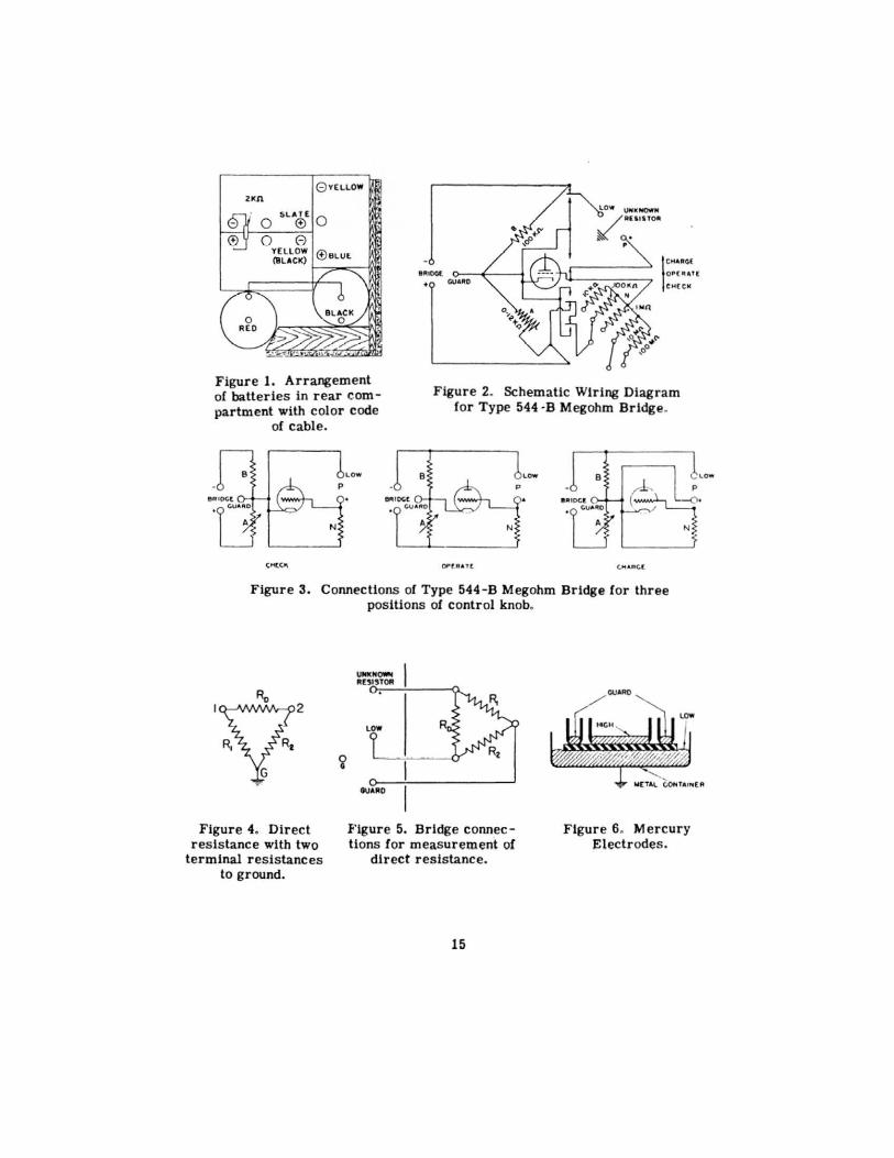
When the unknown resistor has its own insulating supports, it is no longer a two-terminal resistor, but is a three-terminal resistor, ground being the third terminal. It has three resistances, as shown in Figure 4, its direct re sistance RD and its two terminal resistances R1 and R2. When such a resistor Is connected to the UNKNOWN RESISTOR terminals, that terminal resistance which is associated with the terminal connected to the LOW terminal is shorted and the resistance measured by the bridge is that of the direct resistance and the other terminal resistance in parallel.
The direct resis tance RD can be measured by s winging the ground connector to the GUARD terminal and balancing the bridge as described in Paragraph 3.3. A more complete discus sion of the measurement of direct resistance is given in Section 4.0, Paragraph 4.2.

SECTION 4.0 OTHER USES
4. 1 RESISTANCE OF CAPACITORS
While the resistance of a capacitor is measured in the same manner as a pure resistance, as described in Section 3.0, Paragraph 3.1, certain extra precautions must be taken because of the large capacitance which is in parallel with the resistance.
FunctiE>nal wiring diagrams of the bridge are shown In Figure 3. With the control knob set in the CHECK position, the unknown capacitor connected to the UNKNOWN RESISTOR terminals Is placed in parallel with the standard resistor N in the grid circuit of the detector tube. If there is no residual charge in the capacitor, the setting of the ZERO ADIU~ knob will be the same as 1f the parallel capacitor were not present. Any residual charge will cause the zero of the galvanometer to drift until this charge is completely dissipated.
When the control knob is turned to the OPERATE position, the bridge voltage is applied to the capacitor through the standard resistor N. If the time constant RC of capacitor and resistor is only a few seconds, steady state conditions will be set up in the time necessary to operate the various controls. For the largest standard, 100 Mn, used when the MULTIPLY BY switch is ·set at 1000, the capacitor may have a capacitance of 0.01 IJ.f for a time constant oi 1 second and 0.1 IJ.f for a time constant of 10 seconds.
When the time constant is greater than 5 seconds, time wUI be saved by turning the control knob to the CHARGE position. This removes the standard resistor N from the charging circuit and applies directly to the capacitor a voltage within 10% of that which It will finally have with the control knob set at OPERATE. This process may be repeated as often as desired, rebalancing the bridge each time that the control knob is set at OPERATE.
A time constant of 100 seconds is about as large as it is convenient to use. Mter each adjustment of the bridge, sufficient time must elapse to show In which direction the galvanometer ls moving and this time is proportional to the time constant. This consideration sets an upper llmlt of perhaps 10 IJ.f with the MULTIPLY BY switch set at 100, and 1 j.l.f with this switch set at 1000.
Since It is impossible to check the zero oi the galvanometer in the CHECK position without completely discharging the capacitor, the CHARGE position can be used for this purpose, whenever It has been shown that there are no extraneous potentials induced in the capacitor, as explained below.
4. 11 Dielectric Absorption: All solid dlelectrtc capacitors have dielectric absorption. Ills particularly noticeable in those capacitors having a laminated structure. In addition to the normal charge, there Is a volume charge which slowly dilfuses into the material, requiring minutes, hours and even days to attain equilibrium. The charging current which flows is added to the steady leakage current and glves an instantaneous resistance which is lower than the true leakage resistance.

This phenomenon may be s tudied by maintaining the bridge balance by continual adjustment of the MEGOHMS dial. The resistance at any time may be observed by ceasing to maintain the bridge balance alter that instant and noting the reading. The necessity of reading a continually moving pointer at a specified time is thus avoided. The bridge may then be brought into balance for the next reading. The initial zero adjustment of the bridge must be made with the control knob in the CHECK position so that all resistance values may start from the uncharged condition of the specimen.
When dielectric absorption exists, it has been customary to observe the instantaneous resistance one mlnute after the application of the charging voltages and call that the insulation resistance. Such a resis tance value is, however, merely a measure of dielectric absorption and may have little relation to true insulation resistance. The rate of change of resistance with time is a better measure of insulation resistance, because it suggests by its magnitude a possible upper limit of resistance. •
If the time constant of the unknown capacitor and the standard resistor is greater than a few seconds, the initial charging current will not have ceased before observations on the dielectric absorption are begun. The actual values of resistance as observed will then depend somewhat on the setting of the MULTIPLY BY switch. It is usually advisable to use as small a multiplying factor as possible and allow the setting of the MEGOHMS dial to pass up into the second decade. It is sometimes preferable to throw the control knob to the CHARGE position for a definite time interval, say one minute, before passing to the OPERATE position. This procedure eliminates the initial charging current, but leaves the first part aC the curve dependent on the setting of the MEGOHMS dial while the charging took place.
The lime required to dissipate a volume charge, when the terminals of a capacitor are shorted, is approximately the same as the charging time. The presence of a volume charge is shown by a shift in the zero balance of the bridge for the CHECK position from its normal value which is essentially that for the control knob 1n the CHARGE position. The gradual disappearance of thl..s charge may be observed as a drift 1n the galvanometer zero for the CHECK position.
4.12 Charge and Discharge Current: The charging current flowing into the capacitor at any instant may be calculated from the observed resistance P, the standard resistance N, and the voltage E applied to the bridge.
I= _E_ = lOE N + P M(1 + 100)
p.a (1)
•R. W. Wiesman, "Insulation Resistance of Armature Windings", Electrical Engineering, June, 1934. Murphy and Morgan, "The Dielectric Properties of Insulating Materials", Bell System Technlcal1ournal, July, 1939.
6
where M is the setting of the MULTIPLY BY switch and D the reading of the MEGOHMS dial. The voltage E applied to the bridge may be measured by a high resistance voltmeter connected across the BRIDGE terminals. The voltmeter resistance must be sufficiently high (at least 1 MO) so that its applicaUon does not affect the bridge voltage.
The discharge current flowing out of a capacitor which has been previously charged may be measured in the following manner. A piece of mica or other thin but high-resistance insulator is slipped in between contacts 2 and 4 of the control switch when set in the OPERATE position. These contacts are shown in Figure 8 and are the two nearest the panel in the outside r ow. The LOW terminal is then connected to the + BRIDGE terminal. The charged capacitor is connected to the UNKNOWN RESilUOR terminals in a direction reversed from its connection during charge. The bridge will balance in the same manner as during the charging cycle. The resistance read tn the normal way is the resistance which the capacitor would have if the voltage across it were normal. The discharge current ls given by Equation (1).
4. 13 Extraneous Potentials: Unshielded resistors and capacitors, especially those having large physical dimensions, may have a volt.age induced in them by an external electrostatic field. This is usually an alternating potential, because alternating electric fields at the power supply frequency are usually present in laboratories, factories and power houses. An aprreclable voltage may also be induced in the lead from the high UNKNOWN terminal to theresistor if this lead ls long and unshielded, particularly U it is allowed to Ue next to the attachment cord. The effect of this induced voltage is to change the effective bias of the detector tube and hence the galvanometer deflection. As s hown in Figure 3, the unknown and standard resistors are connected in parallel in the grid circuit of the detector tube in exactly the same way in both the CHECK and OPERATE positions. If then the zero adjustments are made with the control knob in the CHECK pos ition, the effect of the induced voltage wtll be eliminated. Even a large induced voltage will not eause a direct error in the bridge balance, provided the zero adjustment can sttll be made.
The existence of induced voltage is disclosed by a dl!ference in the zero balance for the CHECK and CHARGE positlons. Alternating voltages affect the balance as well as direct voltages, because the tube rectlfles as well as a.mpllfles.
4.2 DffiECT RESISTANCE
The direct resistance of a three-terminal resistor may be measured by connecting the third terminal to the GUARD terminal, as shown in Figure 5. There are three cases dependent on the method of grounding of the three- termlna.l resistor. For each of these the bridge must be grounded at a different junction.
4.21 One Main Terminal Grounded: The grounded terminal is connected to the LOW terminal and the spring connector pivoted on the G terminal sW'Wlg to LOW. This connection is used for grounded insulators and cables when the
7
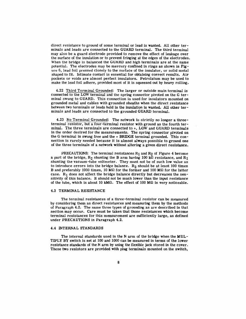
direct r esistance to ground of some terminal or lead is wanted. All other terminals and leads are connected to the GUARD terminal. The third terminal may also be a guard electrode provided to remove the effect of leakage over the surface of the insulation or to prevent friJlting at the edges of the electrodes. When the bridge Is balanced the GUARD and high terminals are at the same potential. The electrodes may be mercury confined ln rings as shown in Figure 6, lead foil pressed closely to the surface of the insulator, or solid metal shaped to fit. Intimate contact is essential for obtaining correct results. Air pockets or voids are almost perfect insulators. Petrolatum may be used to make the lead foil adhere, provided most of 1t is squeezed out by heavy rolling.
4.22 Third Terminal Grounded: The larger or outside main terminal Js connected to the LOW terminal and the spring connector pivoted on the G terminal swung to GUARD. This connection is used for insulators mounted on grounded metal and cables with grounded sheaths when the direct reslsta.nce between two terminals or leads held in the insulation is wanted. All other terminals and leads are connected to the grounded GUARD terminal.
4.23 No Terminal Grounded: The network ls strictly no longer a threeterminal resistor, but a four-terminal resistor with ground as the fourth terminal. The three terminals are connected to+, LOW and GUARD terminals In the order desired for the measurements. The spring connector pivoted on the G terminal Is swung free and the+ BRIDGE terminal grounded. This connection Is rarely needed because it is almost always possible to ground one of the three terminals of a network without altering a given direct resistance.
PRECAUTIONS: The terminal resistances Rt and R2 of Figure 4 become a part of the bridge, R2 shunting the B arm having 100 kCl resistance, and Rt shunting the vacuum -tube voltmeter. They must not be of such low value as to Introduce errors Into the bridge balance. R2 should be at least 100 times B and preferably 1000 times, 10 Mn for the former and 100 Mn for the latter case. R1 does not affect the bridge balance directly but decreases the sensitivity of this balance. It should not be much lower than the input resistance of the tube, which is about 10 kMCl . The effect of 100 MO is very noticeable.
4.3 TERMINAL RESISTANCE
The terminal resistances of a three-termtnal resistor can be measured by considering them as direct resistances and measuring them by the methods of Para&raph 4.2. The same three types of grounding as are described in that section may occur. Care must be taken that those resistances which become terminal resistances for this measurement are sufficiently large, as defined under PRECAUTIONS in Paragraph 4.2.
4.4 INTERNAL STANDARDS
The internal standards used in the N arm of the bridge when the MULTIPLY BY switch Is set at 100 and 1000 can be measured in terms of the lower resistance standards of theN arm by ~ the flexible jack stored in the cover. These two resistors are provided with plug terminals mounted on the switch,
8

which can be reached by the flexible jack through a hole ln the panel. The two plug terminals are arranged in the same order from left to right as the switch positions. The other end of the jack is connected to the LOW terminal.
With the jack on the left terminal and the MULTIPLY BY switch set at 10, the standard resistor for the 100 position is measured in terms of the standa.rd for the 10 position with the MEGOHMS dial at approximately 1. With the jack on the right terminal the standard resistor for the 1000 position is measured in terms of the tO-position standard when the MULTIPLY BY switch is set at 10. The standard resistor for the 10 position is adjusted to 0.25% and the MEGOHMS dial is calibrated to 2%. These measurements are thus accurate to 3% and can serve only as a check on the internal standards. Greater accuracy can be attained by the use of an external decade resistor as explained in Paragraph 4.5.
4.5 EXTERNAL DECADE RESISTOR
The logarithmic resistor, A, controlled by the MEGOHMS dial may be replaced by a suitable decade resistor by opening the A arm at some point (by placing a piece of paper or other thin insulator under the contact arm of the logarithmic resistor) and connecting the decade resistor to the GUARD and + BRIDGE terminals. The case of the decade resistor should be grounded. The bridge is then balanced by means of this decade resistor and the MULTIPLY BY switch.
R (megohms) = 10•000 x M x R(decade)
where M is the setting of the MULTIPLY BY switch.
The Type 1432-1 Decade Resistor• covers the same range as the logarithmic resistor with an accuracy of 0.05%.
The three lower standards Jn the N arm and the resistor Jn the B arm are adjusted to an accuracy of 0.25%. Hence, readings can be made with the MULTIPLY BY switch set at 0.1, 1, 10 to an accuracy of 0.6%. The two higher standards in the N arm can be measured by the method of Paragraph 4.4, using a suitable decade resistor, to an accuracy of 0.6%. Hence, readings with the MULTIPLY BY switch set at 100 and 1000 wUl have an accuracy of 1% when the proper correction for the standard is applied.
4.6 SUBSTITUTION METHODS
Two resistors having resistance values in the same decade may be compared with roe another with an error which is the same as that a! a direct measurement. The entire error is that of reading the MEGOHMS dial, 2% for each setting. The maximum error of the comparison Is 4%, which is the same as that of a direct reading with the MULTIPLY BY switch set at 100 and 1000.
When the two resistors are nearly equal, the settings of the MEGOHMS
•see General Radio Catalog for data.
9

dial are nearly the same and the error is reduced to that of reading the difference of the two settings.
When an extern.1l decade resistor is used, as suggested in Paragraph 4.5, the maximum error ci the comparison is 0.2%, provided that this is not limited by the sensitivity of the bridge balance. For nearly equal resistors the error is determined entirely by the precision of balance.
4.61 lntercomparison of Standards: Sets of standards may be compared by means of an external decade r esistor to an accuracy of about 0.1% over the range from 10 kr! to 10 kMU. For this comparison it is desirable to have· pairs of s tandards of values 1, 2, 5 per decade . Any other combination will suffice which allows each standard to be compared directly with a number of those of lower value connected in series. The two 1's are first compared, then the 2's with the 1's in series. Next the 5's are compared with the 2's and a 1 in series and finally the lO's, 1 's of the next decade, are measured in terms of the two 5's in series.
4.611 Voltage Coefficient: An important source of error will occur if the res istors have an appreciable voltage coefficient of resistance. Each resistor is first measured so as to have across it nearly the full voltage of the bridge. Then it is placed in series with other resistors so that it has across it onehalf Its former voltage or less. The voltage coefficient may be measured by varying the bridge voltage as hxlicated in Paragraphs 4.8 and 5.4. Corrections may then be applied in order to correct the measured resistance to a constant voltage.
4. 7 SENSITIVITY
The sensitivity of the bridge balance varies by almost 10 to 1 over the main decade of the MEGOHMS dial as arm A decreases from 10 kO to 1 kO. The 200 0 shunt placed across the galvanometer decreases its sensitivity by a factor of 4.3. This figure ls approximately the ratio of sensitivities of the a -c and battery detector tubes Types 6K7G and lD5G. The sensitivity of bridge balance with battery tube or with a-c tube and galvanometer shunted is 1.3% at the 10 end of the main decade with 100 volts applied to the bridge. The sensitivity is improved to about 0.3% with 500 volts applied to the bridge or with 100 volts, a-c tube and shunt removed. A maximum sensitivity of 0.06% holds for the latter case with 500 volts. For r esistances in the A arm less than 1 kO, the sensitivity expressed in percent increases to 0.6% for 100 n, 6% for 10 n, 60% for 1 n.
4.8 BRIDGE VOLTAGE
The input terminals of the bridge appear on the left s ide of the panel marked+ -BRIDGE. The voltage across the bridge can be measured by connecting a high resistance voltmeter to these terminals. The resistance of this voltmeter should be high (at least 1 Mn) compared to the bridge resistance . The minimum allowable depends also on the regulation of the power supply.
When a grounded resistor is to be measured, its ungrounded terminal will be positive. This terminal can be made negative by transposing the leads from power supply to bridge. This change is most easily made at the BRIDGE ON - OFF switch. The connections to the galvanometer should also be reversed
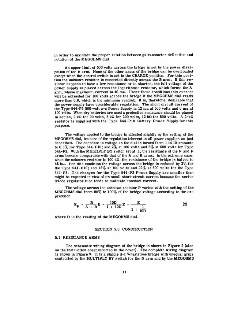
in order to maintain the proper relation between galvanometer deflection and rotation of the MEGOHMS dial.
An upper limit of 500 volts across the bridge 1s set by the power dissipation of the B arm. None of the other arms of the bridge can be overloaded except when the control switch is set 1n the CHARGE pos ition. For this position the unknown resistor is connected directly acros s the B arm. If this resistor happens to have a low resistance or is shorted, the full voltage of the power supply is placed across the logarithmic resistor, which forms the A arm, whose maximum current is 40 ma. Under these conditions this current will be exceeded for 100 volts across the bridge if the MEGOHMS dial reads more than 0.8, which is the minimum reading. It is, therefore, desirable that the power supply have considerable regulation. The short circuit current of the Type 544-P3 500-volt a-c Power Supply is 12 ma at 500 volts and 6 ma at 100 volts. When dry batteries are used a protective resistance should be placed in series, 2 kn for 90 volts, 5 kn for 200 volts, 12 kn for 500 volts. A 2-kn resistor is supplied with the Type 544-P10 Battery Power Supply for this purpose.
The voltage applied to the bridge is affected slightly by the setting of the MEGOHMS dial, because of the regulation inherent In all power supplies as just described. The decrease in voltage as the dial is turned from 1 to 10 amounts to 0.3% for Type 544-P10; and 2% at 100 volts and 5% at 500 volts for Type 544- P3. With the MULTIPLY BY switch set at . 1, the resistance of theN and P arms become comparable with that of the A and B arms. In the extreme case, when the unknown resistor is 100 kSl, the resistance of the bridge Is halved to 55 kfl . For this condition the voltage across the bridge is reduced by 2% for the Type 544-PlO; and 12% at 100 volts and 29% at 500 volts for the Type 544-P3. The changes for the Type 544-P3 Power Supply are smaner than might be expected in view of its small short-circuit current because the series triode regulator tube tends to maintain constant current.
The voltage across the unknown resistor P varies .with the setting of the MEGOHMS dial from 90% to 100% of the bridge voltage according to the expression
B Ep = --E A+ B
10D 1 + lODE
E 1
1 + 10D
where D is the reading of the MEGOHMS dial.
SECTION 5.0 CONSTRUCTION
5.1 RESISTANCE ARMS
(2)
The schematic wiring diagram of the bridge is shown in Figure 2 (also on the instruction sheet mounted in the cover). The complete wiring diagram is shown in Figure 9. It is a simple d-e Wheatstone bridge with unequal arms controlled by the MULTIPLY BY switch for theN arm and by the MEGOHMS
11

dial for the A arm . All of the resistors are wire wound except the two highest res istances in theN arm, which are deposited carbon. Their resistance values, error of adjustment, temperature coefficient and voltage coefficient are given in Table I. The error given for the A arm is for the main decade of the dial over which the logarithmic shape of the res istor keeps the fractional accuracy es sentially constant. Its resistance In kilohms at any setting is ten Urnes the recipr ocal of the dial r eading.
TABLE
Arm Switch R Type
B 100 k!2 Wire A o-1.25 kn Wire N 0.1 10 k!2 Wire
1 100 kn Wire 10 1 Mn Wire
100 10 Mn Depos ited 1000 too Mn Carbon
5.2 VACUUM-TUBE VOLTMETER
Error in % Arm Bridge
.25 2.0 .25 3 .25 3 .25 3
1.0 4 1.0 4
Coefficients in % Temp. Volt.
.01 .00
.01 .00
.01 .00
.01 .oo
.01 .00 -.04 .0001 -.06 .0002
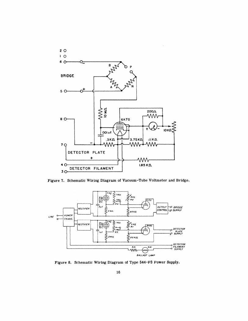
Bridge balance is indicated by means of a vacuum -tube voltmeter whose connections are s hown schematically in Figure 7 and completely in Figure 9. Supercontrol pentodes, Type 1D5G and Type 6K7G, are used in order to obtain suffi cient mutual conductance at the low plate voltage necessary to keep the grid current less than 100 JlJla. Grid, screen and plate voltages are obtained from a voltage divider having a total resis tance of 6 kn and carrying a current of 7.5 ma when used with Type 544-P3 and Type 544-PlO Power Supplies. Plate voltage Is 29 volts. The effective mutual conductances of the two tubes are 60 micr omhos for Type 1D5G and 250 micromhos for Type 6K7G. The 200 n galvanometer shunt used with the a -c tube equalizes these mutual conductances. It may be removed in order to obtain maximum sensitivity for such measurements as those described in Section 4.0, Paragraph 4.6.
The galvanometer has a center zero with a current sensitivity of 100 11a full deflection and a res istance of 660 n . A scale division corresponds to 4 Jla. Increasing the plale current produces a positive deflection of the galvanometer. The rheos tat controlled by the ZERO ADJUST knob balances out the plate current from the galvanometer, counter-clockwise motion corresponding to increased plate current. The pointer of this knob should be approximately within the span of the arrow engraved on the panel for the battery tube and within 15 o
of a left horizonta l position for the a -c tube.
A r esistance of 10 Mn is placed In the grid circuit to prevent an excess ive voltage being placed on the grid of the tube when the bridge is unbalanced. A 0.001 j.l.f capacitor connected from grid to cathode acts with the 10 Mn res is tor as a resistance-capacitance filter to attenuate by a factor of 4 any alternating voltage induced in the unknown resistor and its leads.
12
5.3 SWITCHES
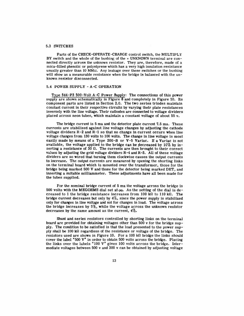
Parts of the CHECK-OPERATE-CHARGE control switch, the MULTIPLY BY switch and the whole of the bushing of the + UNKNOWN terminal are connected directly across the unknown resistor. They are, therefore, made of. a mica-filled phenolic or polystyrene which has a very high insulation resistance usually greater than 10 MMH. Any leakage over these switches or the bushing will show as a measurable resistance when the bridge is balanced with the unknown resistor disconnected.
5.4 POWER SUPPLY - A-C OPERATION
Type 544-P3 500-Volt A-C Power Supply: The connections of this power supply are shown schematically in Figure 8 and completely in Figure 10. Its component parts are listed in Section 2.0. The two series triodes maintain constant current in their respective circults by varying their plate resistances inversely with the line voltage. Their cathodes are connected to voltage dividers placed across neon tubes, which maintain a constant voltage of about 55 v.
The bridge current is 5 ma and the detector plate current 7.5 rna. These currents are stabilized against line voltage changes by adjusting the cathode voltage dividers R-2 and R-1 so that no change in current occurs when line voltage c~es from 130 volts to 100 volts. The change in line voltage is most easily made by means of a Type 200-B or V-5 Variac. If a Variac is not available, the voltage applied to the bridge can be ~ecreased by 10% by inserting a resistance of 30 n. The currents are then brought to their correct values by adjusting the grid voltage dividers R-4 and R-3. All of these voltage dividers are so wired that turning them clockwise causes the output currents to increase. The output currents are measured by opening the shorting links on the terminal board which is mounted over the transformer, those for the bridge being marked 500 V and those for the detector being marked DET, and inserting a suitable milliammeter. These adjustments have all been made for the tubes supplied.
For the nominal bridge current of 5 ma the voltage across the bridge is 500 volts with the MEGOHMS dial set at oo. As the setting of the dial is decreased to 1 the bridge resistance increases from 100 kO to 110 kU. The bridge current decreases but only by 4%, since the power supply is stabilized only for chaJltes in line voltage ard not for changes in load. The voltage across the bridge increases by 5%, while the voltage across the unknown resistor decreases by the same amount as the current, 4%.
Shunt and series resistors controlled by shorting links on the terminal board are provided for obtaining voltages other than 500 v for the bridge supply. The condition to be satisfied is that the load presented to the power supply shall be 100 kO regardless of the resistance or voltage of the bridge. The resistors used are shown in Figure 10. For a 100 kU bridge the links should cover the label •500 V" in order to obtain 500 volts across the bridge. Placing the links over the labels "100 V" gives 100 volts across the bridge. Intermediate voltages between 500 v and 300 v can be obtained by adjusting voltage
13
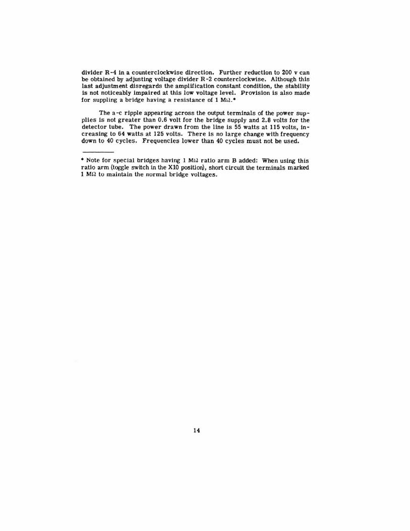
divider R -4 in a counterclockwise direction. Further reduction to 200 v can be obtained by adjusting voltage divider R-2 counterclockwise. Although this last adjus tment dis regards the amplification constant condition, the stability is not noticeably impaired at this low voltage level. Provision is also made for suppling a bridge having a res istance of 1 MU. •
The a -c ripple appearing across the output terminals of the power supplies Js not greater than 0.6 volt for the bridge supply and 2.8 volts for the detector lube. The power drawn from the line is 55 watts at 115 volts, in· creasing to 64 watts at 125 volts. There is no large cha.nge with frequency down to 40 cycles. Frequencies lower than 40 cycles must not be used.
• Note for s pecial bridges having 1 M~~ ratio arm B added: When us ing this ratio arm (toggle switch in the XlO position), short circuit the terminals marked 1 Mn to maintain the normal bridge voltages.
14
0 V£LLOW
SLAt£ Q 0 0
GUAAO lCHlOG(
OP( .. AT [
tt4(CK
Figure 1. Arrangement of batteries in rear compartment with color code
Figure 2. &hematic Wiring Diagram for Type 544 ·B Megohm Bridge.
of cable.
LOW
Figure 3. Connections of Type 544-B Megohm Bridge for three positions of control knob.
Figure 4. Direct resistance with two
terminal resistances to ground.
Figure 5. Bridge connections for measurement of
direct resistance.
15
Figure 6. Mercury Electrodes.
2 0
0 6
6RIOGE
5
8
7
+
DETECTOR PLATE
+ 40-----------___.J
DETECTOR FILAMENT 3~---------------------J
200.n.
Figure 7. Schematic Wiring Diagram of Vacuum-Tube Voltmeter and Bridge.
LIN£
BRIDGE SVPPt.Y
'------o0£T£CTON
.-----o. s~~~~
BALLAST L AMP
Figure 8. Schematic Wiring Diagram of Type 544-P3 Power Supply.
16

.... ~
.-----<0·-BRIOGE
:oH
01'1 I S-.J ~ BRIOGE
I
OFF
.DES SOCKET WIRIAG FOR
BATTERY A?WER .su<R.I' 15 44 - PIO)
R- IO
IIO[l;FORH NO 8LADES 2,5tl' 8 12
TO MAX£ CONTA C IN CENT'E:R RJStriON ACSO. 8ENO FOR BREAK 8£FOR£ MAKE OPeRA riON.
t
l CHAR GE
OPERATE
CHECK
MU.TIPLY 8Y
I 10 100 \ I f 1000 J
' /
£/~!GRAVING FD'i S-1
r-1
!.!L£ff 105CPfFor 8affrq~ir71J 6Kl'G fFoT A - C Op#ralion/
Figure 9. Complete Wiring Diagram of Type 544-B Megohm Bridge .
R-16
8-.J
At the bottom is shown the arrangement of terminals for battery power supply.

Parts List for Type 544- B
RESISTORS
R- 1 • 12.2-R- 2 • R-3 s
••• • R·S s
••• • R-7 s
R·8 • R•l • R· IO • R·ll • R· l2 • R·l3 • R· 1\ • R·IS • l-18 • R·l7 •
12. 7 k Oh101 10 k Oh•o
110 Oh.. ~ 1.n k Oh•o
J:lO Oh•o 3. 75 k Oh•o
10 He~h•o 15 Oh01o SO k Oh11o SO k Ohu 10 k Oh• o
100 k Oh"'} I Me70h
10 Me~• 100 Megohu 2. 2 k Oh•o 220 Oh•o
• F<>r 8ettery o•eratlo• only • •• For A-C o, ... tl Oft Oft I r.
* SJ
s•._3"} s ... ,.,
tiOJ IRC tiOJ I RC tl/ ~~ IRC tl/q~ IRC .. ,.~ t l/q~ lAC •• ,.~ llC. * 11. Wll kor
11. Wl lkor 1 0~ 10~
TYPE
5"·332 301
en 8•1/2 w.q WW-q
WW-3
-,5 C1·1 C1·2 Sqll-32'1 ' 811-1''
$-1 • S-2 • $-3 • s-• • $-5 •
5 'o•l t1011 -'Ol OI'ST srsr OI'ST
UTTUIES
5••·"2 339-ll Slt'T·J33 SWT·323 SWT·333
&-1 • •s Volt lurgeooll) 5301 &-2 • q5 Vol t luroeo• I ) 5308 &-3 • •s Volt lurveoo I) 5308 &-q • s Volt (2 lri/J Volt) J • eready 16
HI SCELLMEOUS C·l • c.,ocltor 0. 001 .,f tiO$ Ov~lller III.S
Pl-1 Pl ug
M-1 • Meter 588 · 321
Figure 10. Complete Wiring Diagram of Type 544-P3 Power Supply.
R - 1 • 5 11.0 R-2 • 5 kO R-3 • 1 ),10 R-4 • 1 ),10 R-5 " 33 kn R-8 • 33 1<0 R-7 • 1 ),10 n-8 • 1.8 wo B.-11 • 1.1 MO
Resistors
R-IO • I Mn R-11 c 470 kU R-12 • 1.8 MO R - 13 • 20 kU R· 14 • 5.6 kn R-15 • 80 kU~2% R-17 • 2511.0;2% R-18 • 27 0 -R-111 • 11.8 n
Capacitors
C - 1 • 2.0 lif C-2 • 1.0 lif C-3 • 1.0 lif
}'uses
For 115 roll operation: F-1 • 0.8 amp. Slo-. Blo-. MG F-2 • 0.8 amp. Slow Blow 3AG For 230 Yolt operation: F - 1 • 0.4 amp. Slow Blow 3AG F-2 • 0.4 amp. Slow Blow 3AG
18
Tubes
V-1 • T ype 8X5-GT V -2 • Type 5U4-G V-3 • Type 1115-GT V·4 • Type IIKII-GT V - 5 • Type NE-41 V - II • Type NE-41 v -7 • 8J 11'a.llla Type 4A 1
Transformer T-1 • CR 3115 · 410-2

'i':rp~ 54-',-3 Oper(t t in; Instl·:;,:;t::..·):.1S
Foe- ·u.:-.·t.tt:l.:.·:: oper ill:.i o:1 , th3 va -::::mir.l tube no·,; u:.;e.::l. u.r:d surr ::.:..<. · __ -r..·~ ·.:
T".(l-J3 114 ;r;ini •"t -:.: :.- ~ ;·.-.;.~·.b)!:' th:.n ~he Tn :;e :D5-G :)c~l :.:-,d.:.~·.:. :. .:=:! in i:.he ::Jf.er:;:.t.ir.,: instr,Jc7.i s~i~. '"' . ·.i:-t:~ tur c-t . .)- OCL-'.!.1 ,-:;c~V.et :..d.:-..lYt e r is ::;~;.p .t.J..~:t . A .:;i:&;;l ~ l . 5-vol·C. ~6 ';)<.:.t t:.~l·. · is r: ~· ;.r us::!d <ln:i is s upplie:i .
Til e t·?.si ..;'!;ar :ohmm in t he ::.'Jl :.i- poi n t conne~ to:- f :> r t:1e t.l t t; !~•7 ::>up!J~:-·
( CI.-.-3 on FfL 17 .:-..nd 13 ) is r ~pll.l~G~l o~r a shart- :::i:-.::ui t. ~nd :::. !'te· .... re~i.:;tor !i:-S of 220 ohms , B~:-l/2 5% , i.:; connected oehrean the o·.::t~1-sacket teruinc.~.l :/6 c:.nd cne side ::>f Cl.-'5. For battery a per-:. tiol: , 'th e lL4 i8 trbde c ·.:mnacted O.;lJ. the mini.;;. turetc-ock.l .s..l•!?t.P.r c.uta.~tic~1.11y connects the 220-o~ resistor , n-0 , ir. paral1.:;l \·rith n-5 (p~;;, C 17) lO!:' prop~ !' ~i;J.3 .::onnectio:-~.
Form 453- Il
G£:l;.:;_:uu.. ?-....u.JI O C01'.2i·;.;:n Cambridge 3~), l·~c:::.ssachusetts
July, 1') 54