Embed Size (px)
Citation preview
MegaVideo® Flex Installation Manual
Models:
1.2 Megapixel
AV1195DN
AV1195DN-NL
1080p
AV2195DN
AV2195DN-NL
AV2196DN
AV2196DN-NL
3 Megapixel
AV3195DN
AV3195DN-NL
AV3196DN
AV3196DN-NL
5 Megapixel
AV5195DN
AV5195DN-NL

Installation Manual
Page | 2 [email protected]
+1.818.937.0700 877.CAMERA.8 www.arecontvision.com [email protected]
MegaVideo® Flex
Contents
Package Contents ................................................................................................................................................... 3
Camera Overview.................................................................................................................................................... 6
Mounting the Sensor Unit ...................................................................................................................................... 7
Mounting the Main Unit ........................................................................................................................................ 10
Connecting the Sensor, Main Unit and Optional IR ......................................................................................... 11
Reset to Factory Default ...................................................................................................................................... 12
Changing the Lens ................................................................................................................................................ 12
Removing the Bubble ........................................................................................................................................... 12
Attaching the Bubble ............................................................................................................................................. 12
Camera Power Up ................................................................................................................................................. 14
SD Card Set-up ..................................................................................................................................................... 16
SD Card Tab .......................................................................................................................................................... 19
SD Card Setup via AV200 ................................................................................................................................... 20
Camera Discovery, Setup, and Configuration .................................................................................................. 22
Network Protocols ................................................................................................................................................. 22
General Remote Focus ........................................................................................................................................ 23
Refined Remote Focus ......................................................................................................................................... 24
AV IP Utility Focus Tab ........................................................................................................................................ 26
Mounting Templates ............................................................................................................................................. 27
Support ................................................................................................................................................................... 29

Installation Manual
Page | 3 [email protected]
+1.818.937.0700 877.CAMERA.8 www.arecontvision.com [email protected]
MegaVideo® Flex
CAUTION!
1. Do not attempt to service a damaged unit yourself. Refer all servicing to qualified service
personnel.
2. Wiring methods shall be in accordance with the National Electrical Code/NFPA 70/ANSI, and
with all local codes and authorities having jurisdiction. Wiring should be UL Listed and/or
Recognized wire suitable for the application.
3. Always use hardware e.g. screws, anchors, bolts, locking nuts etc. which are compatible with
mounting surface and of sufficient length and construction to insure a secure mount.
Package Contents
This equipment should be unpacked and handled with care. The original packaging is the safest
container in which to transport the unit and can be used if returning the unit for service. The packaging
contains:
Installation Manual
Page | 4 [email protected]
+1.818.937.0700 877.CAMERA.8 www.arecontvision.com [email protected]
MegaVideo® Flex
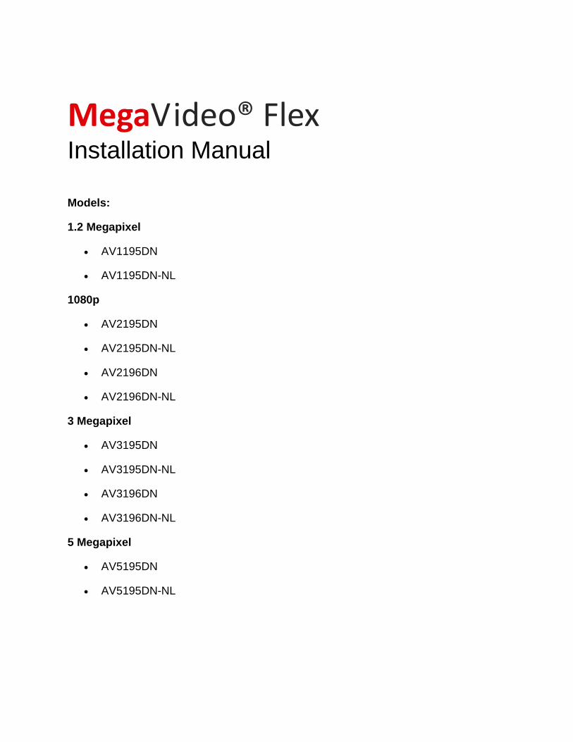
Reference # Description
1 1x Main Unit
2 2x Black Camera Fastening Nuts, 1x White Fastening Nut
3 1x Metal Sheet Bracket with Attached Plate
4 1x Sensor Unit
5 1x White Cover with Bubble
6 1x 5ft USB 2.0 to Micro USB 28/28 AWG, Shielded Twisted Pair Cable, No Active Repeater
7 1x 40ft USB 2.0 to Micro USB 28/24 AWG, Shielded Twisted Pair Cable, No Active Repeater
8 2x #6-32 1” Wood/ Metal Sheet Screw
9 4x #6-32 1.5” Wood/ Metal Sheet Screw
10 6x #6-32 1” Drywall/ Masonry Mounting Anchors
11 4x #6-32 1.5” Machine Screw
12 6x #6-32 Hex Nut
13 2x #6-32 1” Machine Screw
14 8x #6-32 Washer
15 1x #6-32 Hex L-key
16 3x Zip Ties
17 1x M1.2 Set Screw Driver
1x 4-position I/O connector
108 9 11
12
13
14
15
16
17

Installation Manual
Page | 5 [email protected]
+1.818.937.0700 877.CAMERA.8 www.arecontvision.com [email protected]
MegaVideo® Flex
1x Mounting Template for Main Unit
1x Mounting Template for Sensor Unit
1x CD with Manual and Software
NOTE: Make sure not to miss match sensor units and main units from different boxes if you are going
to install more than one MegaVideo Flex camera.
Warranty Information
Global (3 Year) Limited Warranty
ARECONT VISION warrants to Purchaser (and only Purchaser) (the “Limited Warranty”), that: (a) each
Product shall be free from material defects in material and workmanship for a period of thirty-six (36)
months from the date of shipment (the “Warranty Period”); (b) during the Warranty Period, the
Products will materially conform with the specification in the applicable documentation; (c) all licensed
programs accompanying the Product (the “Licensed Programs”) will materially conform with applicable
specifications. Notwithstanding the preceding provisions, ARECONT VISION shall have no obligation or
responsibility with respect to any Product that (i) has been modified or altered without ARECONT
VISION’s written authorization; (ii) has not been used in accordance with applicable documentation; (iii)
has been subjected to unusual stress, neglect, misuse, abuse, improper storage, testing or connection;
or unauthorized repair; or (iv) is no longer covered under the Warranty Period. ARECONT VISION
MAKE NO WARRANTIES OR CONDITIONS, EXPRESS, IMPLIED, STATUTORY OR OTHERWISE,
OTHER THAN THE EXPRESS LIMITED WARRANTIES MADE BY ARECONT VISION ABOVE, AND
ARECONT VISION HEREBY SPECIFICALLY DISCLAIMS ALL OTHER EXPRESS, STATUTORY AND
IMPLIED WARRANTIES AND CONDITIONS, INCLUDING THE IMPLIED WARRANTIES OF
MERCHANTABILITY, FITNESS FOR A PARTICULAR PURPOSE, NON-INFRINGEMENT AND THE
IMPLIED CONDITION OF SATISFACTORY QUALITY. ALL LICENSED PROGRAMS ARE LICENSED
ON AN “AS IS” BASIS WITHOUT WARRANTY. ARECONT VISION DOES NOT WARRANT THAT (I)
THE OPERATION OF THE PRODUCTS OR PARTS WILL BE UNINTERRUPTED OR ERROR FREE;
(II) THE PRODUCTS OR PARTS AND DOCUMENTATION WILL MEET THE END USERS’
REQUIREMENTS; (III) THE PRODUCTS OR PARTS WILL OPERATE IN COMBINATIONS AND
CONFIGURATIONS SELECTED BY THE END USER; OTHER THAN COMBINATIONS AND
CONFIGURATIONS WITH PARTS OR OTHER PRODUCTS AUTHORIZED BY ARECONT VISION
OR (IV) THAT ALL LICENSED PROGRAM ERRORS WILL BE CORRECTED.
For RMA and Advance Replacement information visit http://www.arecontvision.com

Installation Manual
Page | 6 [email protected]
+1.818.937.0700 877.CAMERA.8 www.arecontvision.com [email protected]
MegaVideo® Flex
Camera Overview The MegaVideo Flex is the only customizable discreet multi-megapixel camera on the market to provide interchangeable lens options with remote focus. The innovative design provides customers with the ability to add infrared illumination (sold separately) via two ports on the main unit. Flexible lens options include: 2.1mm, 2.8mm, 4mm, 6mm, 8mm, 12mm, and 16mm.
The camera’s small footprint gives customers the flexibility to install the MegaVideo Flex in a variety of tight spaces such as ATM machines, gas pumps, or applications where a discreet aesthetic design is required.
The MegaVideo Flex comprises of the camera sensor, metal mounting bracket, two (2) USB 2.0 to Micro USB cables (40ft and 5ft), and the main unit. Installing the MegaVideo Flex is simple and can be mounted a variety of ways.
The MegaVideo Flex cameras are available in 1.2MP, 1080p, 3MP and 5MP resolutions. The cameras are ideal for indoor or outdoor use and delivers excellent low light imaging. For applications with bright or over saturated lighting conditions, optional wide dynamic range delivers up to 100dB at full resolution and is available on select 1080p and 3MP models. For applications with poor low lighting conditions, the MegaVideo Flex 1.2MP model features NightView™, making it capable of covering areas where very little light is present. Binning Mode increases the camera’s low light performance by combining pixels so that more light can be collected (available on 3MP and 5MP models).
Once mounted, the operator can quickly focus and position the camera remotely, eliminating the need to adjust the camera on-site. No more hassle individually installing multiple cameras to cover a wide area, manually focusing lenses, or risk missing critical information.
The camera offers advanced streaming capabilities and is designed on an efficient H.264 encoding platform capable of delivering high quality video without straining the network. Power can be supplied via a single Power-over-Ethernet compliant network cable or with power from a 12-48V DC/24V AC power supply.
The camera's interface allows for an intuitive, fast, and easy configuration; while the Free AV IP Utility tool allows users to quickly configure multiple cameras at one time. The MegaVideo Flex is ONVIF Profile S (Open Network Video Interface Forum) and PSIA (Physical Security Interoperability Alliance) compliant, providing interoperability between network video products regardless of manufacturer.

Installation Manual
Page | 7 [email protected]
+1.818.937.0700 877.CAMERA.8 www.arecontvision.com [email protected]
MegaVideo® Flex
Mounting the Sensor Unit 1. Determine a secure location to mount the camera.
2. The camera can be mounted four ways: by cutting a hole and mounting the camera directly to a
metal/wood surface or by using the supplied metal mounting bracket and attaching it to a
metal/wood surface or via the ¼” 20 UNC thread, or via the MF-FMA flush mount bracket (sold
separate). Choose the best method for your installation:
a. Directly Mount Sensor to Surface: This method is for use when you have access to
the unit from behind the wall or surface. Use the supplied template or 1 7/8” hole saw to
cut a hole in the surface for the sensor. Follow the instructions in the table below:
Reference # Description
1 Attach one of the two camera fastening nuts along the front edge of the camera bubble.
2 Insert the camera module through the front of the hole until the fastening nut is flush
with the surface.
3 Insert the other camera fastener nut on the back of the camera and tighten until securely in place.
4 Use the supplied Hex L-key to lock the set screws on both fastening nuts in place. Do not over torque the screws.
Note: steps may need to be reversed depending on the amount of space to tighten the fastening nut
inside the surface.

Installation Manual
Page | 8 [email protected]
+1.818.937.0700 877.CAMERA.8 www.arecontvision.com [email protected]
MegaVideo® Flex
b. Mounting Camera Via Metal Bracket: This method is recommended if you want to
minimize drilling holes into a surface. Follow the instructions in the table below:
Ref # Description
1 / 2 The metal sheet bracket plate (#1) and the metal sheet bracket base (#2) should already be attached. The bracket plate can be adjusted up or down with a Philips head screwdriver.
3 Attach one of the two camera fastening nuts along the front edge of the camera bubble.
4 Insert the camera module through the front of the hole until the fastening nut is flush with the metal sheet bracket.
5
Insert the other camera fastener nut on the back of the camera and tighten clockwise until securely in place. Use the supplied Hex L-key to lock the set screws on both fastening nuts in place. Do not over torque the screws.
6 / 7
For Drywall/ Masonry application: Securely fasten the metal sheet bracket by first installing 2x of the #6-32 1” Drywall/ Masonry Mounting Anchors (#6), place the metal sheet bracket opening over the Drywall Mounting Anchors and use a Philips head screwdriver and install 2x of the #6-32 1” Wood/ Metal Sheet Screws (#7).
8
9
10

Installation Manual
Page | 9 [email protected]
+1.818.937.0700 877.CAMERA.8 www.arecontvision.com [email protected]
MegaVideo® Flex
8 / 9 / 10
For Metal/Wood Sheet application: Prepare surface for installation. Thread a #6-32 Washer
(#8) into each Machine Screw. Then, insert the 2x #6-32 1” Machine Screws (#10) through the
opening of the metal sheet bracket. Fasten securely with a #6-32 Hex Nut (#9) on each.
c. Directly Mount Sensor to Surface: The MegaVideo Flex can be mounted from the top
or bottom via the ¼” 20 UNC thread.
d. Flush Mount: This method is recommended for in-ceiling installations or for surfaces
you want a non-obtrusive flush mount. This method is ideal for areas you do not have
access to behind the unit upon installation.
i. Use the supplied template (provided by MF-FMA) or 2 ¾”hole saw to cut a hole
in the surface for the sensor.
ii. Screw the MegaVideo Flex camera into the MF-FMA (sold separately) in-ceiling
mount until flush with the mount rim. Tighten the set-screws surrounding the rim
of the mount if necessary.
iii. Connect the main unit to the sensor. Pull the network cable through the ceiling
and plug it into the network connector on the camera housing (Note: this can be
done at a later time if there is access to the network connector on the camera
housing after installation into the ceiling).
iv. Check that the indicator LED’s are illuminated to the desired conditions (see LED
Indicator table).
v. Push the two spring actuated retention arms to the upward position and insert the
camera through the ceiling until the retention arms lock into place.
vi. Positioning the lens toward the desired view and tighten the screws on bracket.
Installation Manual
Page | 10 [email protected]
+1.818.937.0700 877.CAMERA.8 www.arecontvision.com [email protected]
MegaVideo® Flex
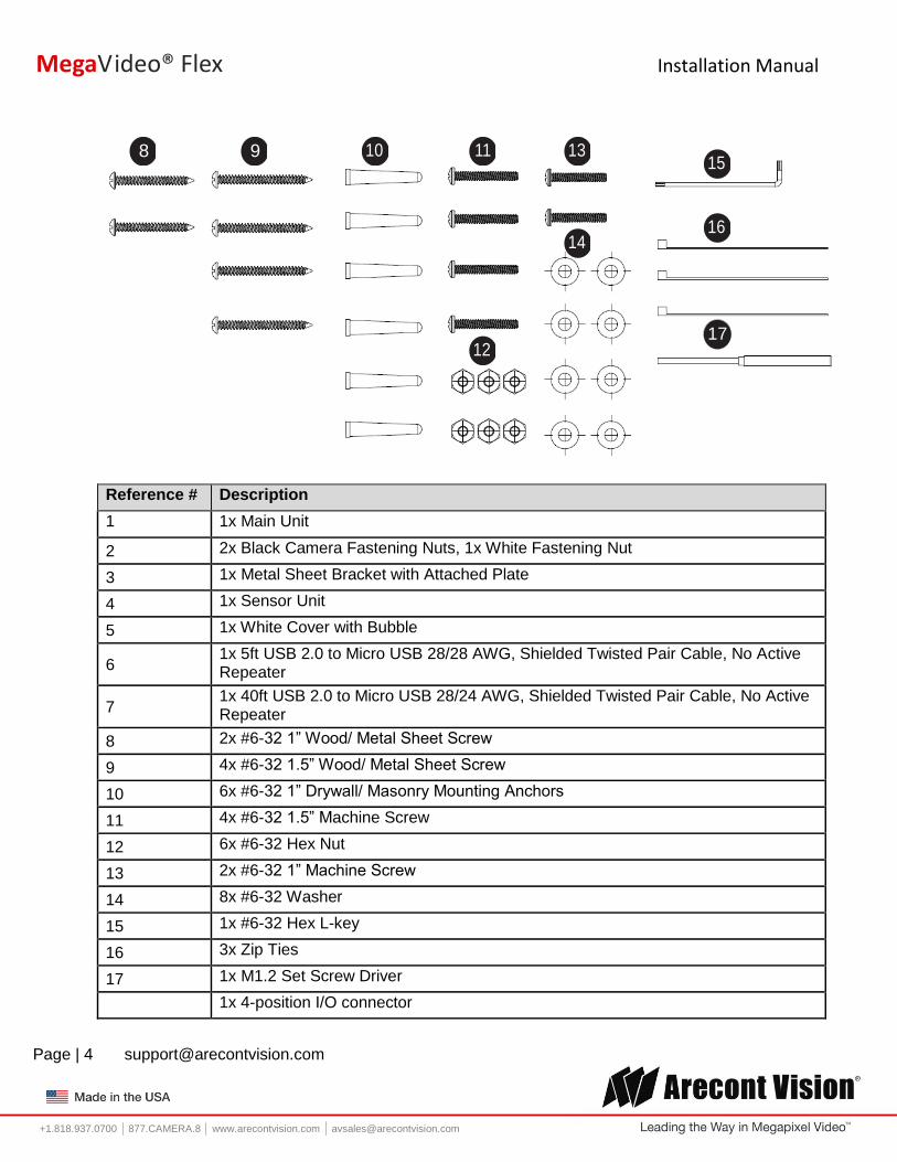
Mounting the Main Unit 1. Determine a secure location to mount the main unit from the camera. There is a 40ft. maximum
distance from the camera to the main unit.
Mount Procedure for Drywall/Masonry Mount Procedure for Metal Application
Ref # Description
For Drywall/ Masonry Applications
1 Prepare surface for installation by placing the main unit where desired and marking each of the four the holes with a pencil.
2 Drill the appropriate size holes to install 4x of the #6-32 1” Drywall/ Masonry Mounting
Anchors (Ref #2) where you marked the pencil holes.
3 Place the holes of the main unit over the Drywall Mounting Anchors and use a Philips head
screwdriver to screw 4x of the #6-32 1.5” Wood/ Metal Sheet Screws (Ref #3).
For Metal/Wood Sheet Applications
4 Prepare surface for installation. Then, insert the 4x #6-32 1.5” Machine Screws (Ref #4)
through the each of the four holes on the main unit.
5 / 6 Thread a #6-32 Washer (Ref #5) into each Machine Screw and then fasten securely with a
#6-32 Hex Nut (Ref #6) on each.

Installation Manual
Page | 11 [email protected]
+1.818.937.0700 877.CAMERA.8 www.arecontvision.com [email protected]
MegaVideo® Flex
Connecting the Sensor, Main Unit and Optional IR
NOTE: When connecting a sensor unit to a main unit, make sure the sensor and main unit are from the
same box. The camera could be undiscoverable if you swap different sensor units on a main unit.
Ref # Description
1
After mounting the main unit and camera sensor to the desired location, insert the USB end of
the supplied 5ft or 40ft cable, depending on your application, to the location on the main unit
that reads “CAMERA” (Ref #1).
2
Insert the Micro-USB side of the cable into the back of the camera.
NOTE: You will need to recycle power once the USB cable is installed on both the sensor unit and the main unit.
3 Using the supplied zip ties, wrap any cable slack around the hook on the back of the camera
to reduce strain.
4
Up to two optional infrared illuminators (AV-IRF) can be attached to the main unit. Each IR
illuminator includes 6 pcs of 850nm LEDs, has a 49.2ft (15 meter) IR distance (max) and an
80° IR angle.
5 Reset button

Installation Manual
Page | 12 [email protected]
+1.818.937.0700 877.CAMERA.8 www.arecontvision.com [email protected]
MegaVideo® Flex
Reset to Factory Default 1. Press and hold the reset button (#5) for 10 seconds and release the reset button. The camera
has been reset to the factory default. If the camera is not connected to DHCP server, the
camera will use a Link-local address.
2. Also can reset to factory default via camera web interface or AV IP Utility
NOTE: Additional information regarding the Arecont Vision® web interface is found separately in the AV
IP Utility Web Browser Manual via the Arecont Vision website.
Changing the Lens 1. Remove the dome cover by loosening the tiny set screw on the ring surrounding the dome cover
with the supplied set screw driver.
2. Turn the metal ring of the bubble counter clockwise and remove.
3. Manually unscrew the lens counter clockwise, this may take several seconds.
4. Screw the replacement lens clockwise until you feel some resistance and hit a hard stop. Do not
over torque the screws.
5. Place the dome cover over the camera sensor and turn it clockwise until it hits a hard stop.
6. Tighten the set screw to lock the dome cover in place.
NOTE: Using MPM16.0 lens, you will need to rotate counter clockwise two (2) turns (720°) after Step 4
to account for the focus shift.
Removing the Bubble 1. To remove the dome cover, loosen the tiny set screw on the ring surrounding the dome cover
with the supplied set screw driver.
2. Turn the metal ring of the bubble counter clockwise to remove.
Attaching the Bubble 1. Place the dome cover over the camera sensor and turn it clockwise until it hits a hard stop.
2. Tighten the set screw to lock the dome cover in place with the supplied set screw driver.

Installation Manual
Page | 13 [email protected]
+1.818.937.0700 877.CAMERA.8 www.arecontvision.com [email protected]
MegaVideo® Flex
Optional: Connecting Digital I/O
To use digital I/O, connect digital I/O with pigtail cable connector on the main unit.
Reference # Description
1 Input
2 Output
NOTE: Camera supports digital input and digital output. See Table 1 for electrical characteristics.
Electrical Characteristics MIN MAX
Input Voltage (V) (Measured between + and – terminals)
ON 2.9 6.3
OFF 0 1.3
Output Current (mA)
(Measured between +
and – terminals)
Applied Voltage
Range: 0-80V
ON - 50
OFF - 0.1
Table 1 NOTE: The digital input is electrically isolated from the rest of the camera’s electrical circuitry via general-purpose photo couplers. The input is additionally protected with a serial 250 Ohm resistor, and a de-bouncing circuit. Duration of any input signal should be at least 5 ms to comply with the requirements of the de-bouncing circuit.
Installation Manual
Page | 14 [email protected]
+1.818.937.0700 877.CAMERA.8 www.arecontvision.com [email protected]
MegaVideo® Flex
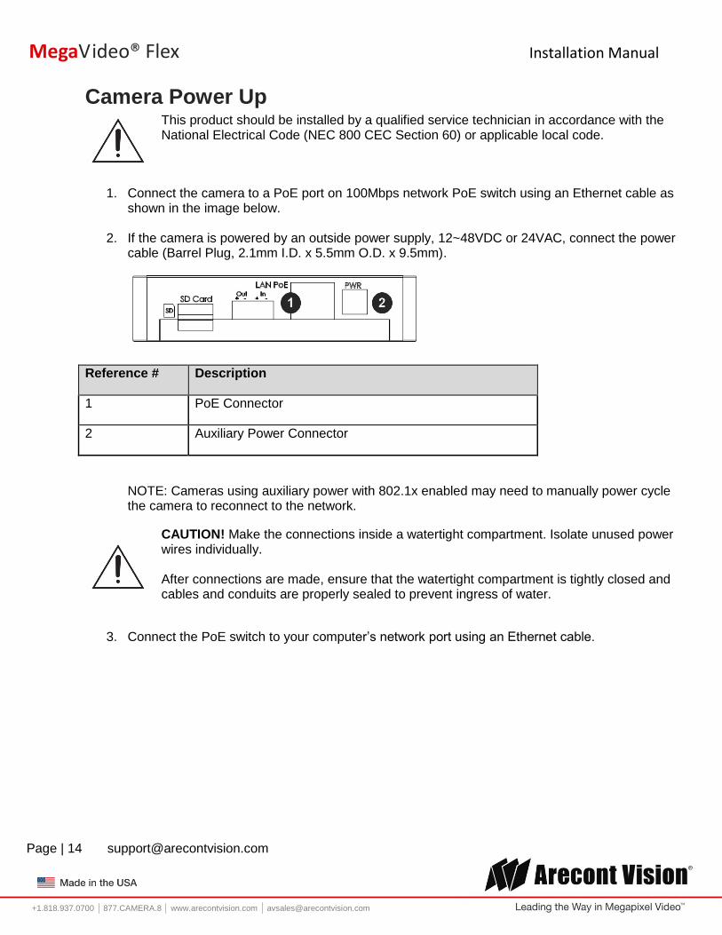
Camera Power Up
This product should be installed by a qualified service technician in accordance with the National Electrical Code (NEC 800 CEC Section 60) or applicable local code.
1. Connect the camera to a PoE port on 100Mbps network PoE switch using an Ethernet cable as shown in the image below.
2. If the camera is powered by an outside power supply, 12~48VDC or 24VAC, connect the power cable (Barrel Plug, 2.1mm I.D. x 5.5mm O.D. x 9.5mm).
Reference # Description
1 PoE Connector
2 Auxiliary Power Connector
NOTE: Cameras using auxiliary power with 802.1x enabled may need to manually power cycle the camera to reconnect to the network.
CAUTION! Make the connections inside a watertight compartment. Isolate unused power wires individually. After connections are made, ensure that the watertight compartment is tightly closed and cables and conduits are properly sealed to prevent ingress of water.
3. Connect the PoE switch to your computer’s network port using an Ethernet cable.
Installation Manual
Page | 15 [email protected]
+1.818.937.0700 877.CAMERA.8 www.arecontvision.com [email protected]
MegaVideo® Flex
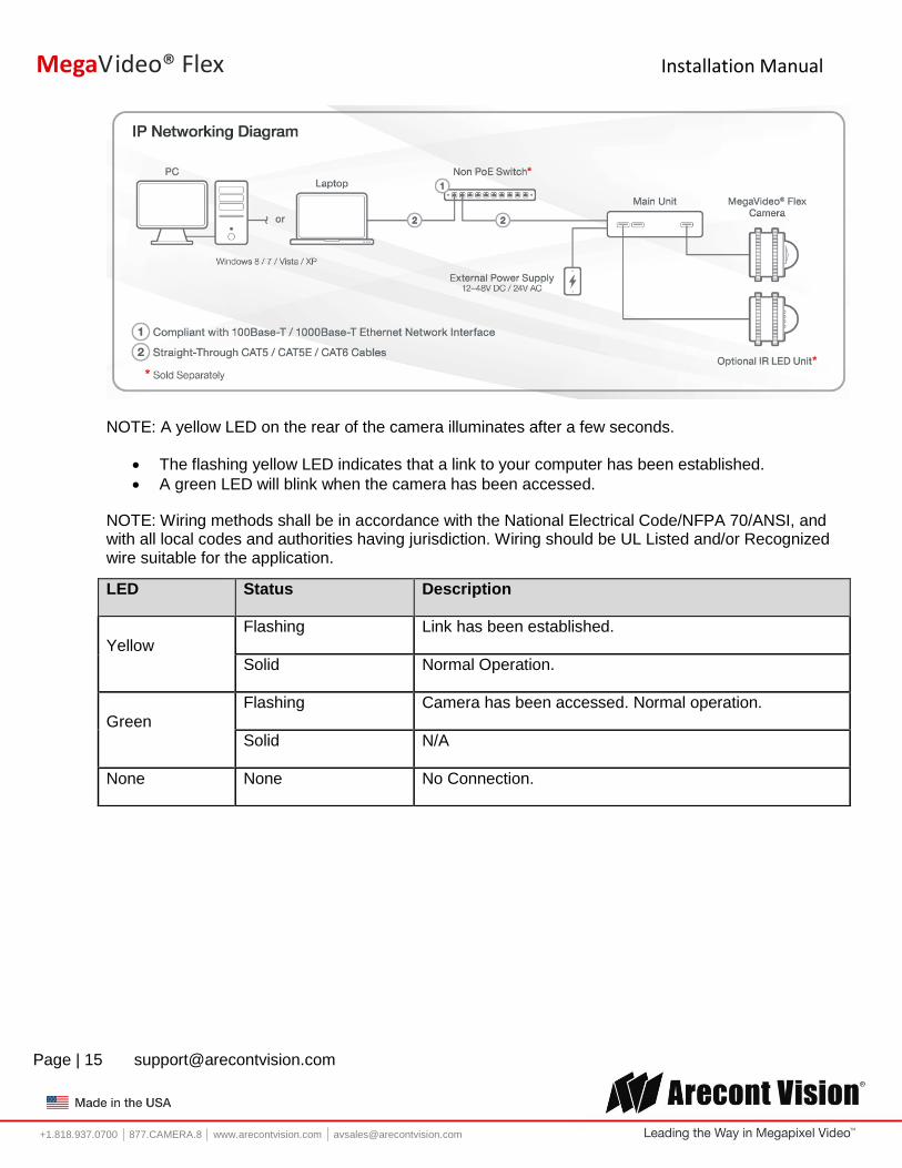
NOTE: A yellow LED on the rear of the camera illuminates after a few seconds.
The flashing yellow LED indicates that a link to your computer has been established.
A green LED will blink when the camera has been accessed.
NOTE: Wiring methods shall be in accordance with the National Electrical Code/NFPA 70/ANSI, and with all local codes and authorities having jurisdiction. Wiring should be UL Listed and/or Recognized wire suitable for the application.
LED Status Description
Yellow
Flashing Link has been established.
Solid Normal Operation.
Green
Flashing Camera has been accessed. Normal operation.
Solid N/A
None None No Connection.

Installation Manual
Page | 16 [email protected]
+1.818.937.0700 877.CAMERA.8 www.arecontvision.com [email protected]
MegaVideo® Flex
Locally Storing Data
The MegaVideo Flex includes a SDHC card slot for onboard storage. To set-up the SD card features, the Web Interface page or AV 200 can be used.
The camera supports class 10 microSD or microSDHC cards up to 32GB. Not all SD cards are the same. Arecont Vision highly recommends using SanDisk Extreme Micro SD cards (or an equivalent substitute) as these cards have been fully tested without issue. The SanDisk Extreme line is better suited for demanding applications like constant recording. Typical lower grade SD cards are meant for multimedia applications and will, at times, have questionable quality and reliability.
Recording to the SD card is FIFO (first in first out). The oldest (first) entry is deleted first as new storage requirements arise. There is no indication when this will happen. Storage time is dependent on a variety of factors such as SD card size and camera FPS.
SD Recording supports video only. Audio is not supported.
SD Card Set-up Insert an SD card (user supplied) into the SD card slot until it locks in place. The location of the SD card slot is located on the main unit. The SD card can only be set-up via the Web Interface or AV200 Software.
Note: Please do NOT insert or remove a SD card while camera is streaming. Note: Upon insertion or removal of a SD card, the camera must be rebooted.
Installation Manual
Page | 17 [email protected]
+1.818.937.0700 877.CAMERA.8 www.arecontvision.com [email protected]
MegaVideo® Flex
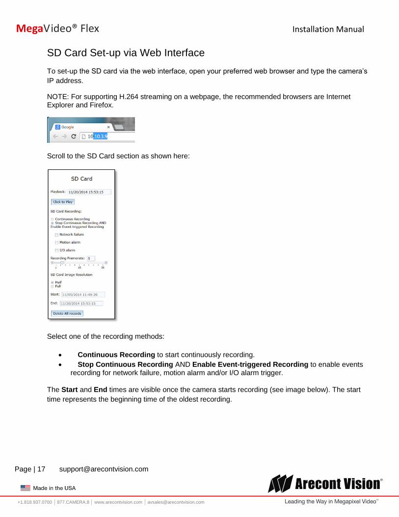
SD Card Set-up via Web Interface
To set-up the SD card via the web interface, open your preferred web browser and type the camera’s
IP address.
NOTE: For supporting H.264 streaming on a webpage, the recommended browsers are Internet Explorer and Firefox.
Scroll to the SD Card section as shown here:
Select one of the recording methods:
Continuous Recording to start continuously recording.
Stop Continuous Recording AND Enable Event-triggered Recording to enable events recording for network failure, motion alarm and/or I/O alarm trigger.
The Start and End times are visible once the camera starts recording (see image below). The start
time represents the beginning time of the oldest recording.

Installation Manual
Page | 18 [email protected]
+1.818.937.0700 877.CAMERA.8 www.arecontvision.com [email protected]
MegaVideo® Flex
To playback recorded video:
Input the date and time of the desired video (must be set between the Start and End time).
Check the Playback SD card video checkbox to play the video.
Playback tips:
Video recorded to an SD card from an Arecont Vision camera can only be played back via an Arecont Vision camera that has the same or lower resolution. Playback can not be viewed with any other device. For example, video recorded to an SD card via a 10MP camera can be played back on a 3MP camera but a 3MP can not be played back on a 10MP model.
SD card must be inserted to any AV camera.

Installation Manual
Page | 19 [email protected]
+1.818.937.0700 877.CAMERA.8 www.arecontvision.com [email protected]
MegaVideo® Flex
SD Card Tab Menu Feature Description
Playback Allows the user to choose the specific time of video to playback.
Click to Play Button to play video specified in the Playback field.
Continuous Recording Allows the user to continuously record without restriction. Default is unchecked box.
Stop Continuous Recording AND Enable Event-triggered Recording
Allows the user to enable events recording when network failure, motion alarm, or an I/O alarm is triggered. Default is unchecked box.
NOTE: if the continuous recording is disabled and no event recording is enabled, the SD card will not initiate recording.
Network Failure Allows the SD Card to record video only in the event that the network fails.
Motion Alarm Allows the SD Card to record video only in the event that motion is detected.
I/O Alarm Allows the SD Card to record video only in the event that an I/O alarm is triggered.
Recording Framerate Allows setting a frame rate output limit for the H.264 video stream. Default value is “Max” minimum fps is 1. Reducing the frame rate output is another way to control the bandwidth used for the H.264 video streaming from the camera trade off is the obvious reduction of frame rate output at the camera. Options are 0 to 30. No default.
SD Card Image Resolution
Provides the ability to set the resolution. Options are Full or Half. Half is the default.
Start Shows the beginning time frame of the video being recorded. No default.
End Shows the ending time frame of the video being recorded. No default.
Delete All Records Allows the user to delete any previously recorded video on the SD card.

Installation Manual
Page | 20 [email protected]
+1.818.937.0700 877.CAMERA.8 www.arecontvision.com [email protected]
MegaVideo® Flex
SD Card Setup via AV200 To set-up the SD card via AV200, launch the AV200 application icon on the desktop.
To enable recording to the SD card, select the desired camera and drag it to the workspace to open a
view. From the window, select the SD card drop down menu. Choose:
Continuous Recording
- OR -
Event-triggered Recording to enable events recording for network failure, motion alarm or I/O
alarm
To launch the SD card playback window, click on the SD card icon.
Set play range to full span sets the playback range to the maximum available on the SD card.
Set playback range allows the user to input the playback date and time manually.
Export play exports an .avi file for playback on most media players.

Installation Manual
Page | 21 [email protected]
+1.818.937.0700 877.CAMERA.8 www.arecontvision.com [email protected]
MegaVideo® Flex
Playback tips:
Video recorded to an SD card from an Arecont Vision camera can only be played back via an Arecont
Vision camera that has the same or lower resolution. Playback can not be viewed with any other
device. For example, video recorded to an SD card via a 10MP camera can be played back on a 3MP
camera but a 3MP can not be played back on a 10MP model.
SD card must be inserted to any AV camera.
Installation Manual
Page | 22 [email protected]
+1.818.937.0700 877.CAMERA.8 www.arecontvision.com [email protected]
MegaVideo® Flex
System Requirements
Computer with Windows XP/Vista/7 operating system, network access, and Microsoft Internet Explorer web browser version 9.0 or later (32-bit).
Camera Discovery, Setup, and Configuration For camera discovery and setup, the AV IP Utility is recommended. The software can be found on the
CD included with your camera or at: http://www.arecontvision.com/softwares.php.
The AV IP Utility has the ability to provide multiple discovery options, including broadcast and multicast,
check the status of a camera, change camera settings, import and export camera settings via a .csv
file, and update firmware and/or hardware from virtually anywhere with a network connection.
Whether used for large installations that require an update to multiple settings, or smaller installations
where only one camera needs changed, the AV IP Utility tool is efficient and convenient for mass or
single camera uploads.
The AV IP Utility tool is compatible with all Arecont Vision® megapixel cameras. The user manual for
the software is included on the CD that came with your camera or available on our website.
Network Protocols The Arecont Vision MegaVideo® Flex cameras support RTSP, RTP/TCP, RTP/UDP, HTTP, DHCP,
TFTP, QoS, IP version 4 (IPv4), IP version 6 (IPv6), and 802.1x.
RTSP – Cameras communicate with video management systems over Real Time Streaming Protocol.
Do not change the RTSP port unless you are sure your VMS does not use the default setting.
RTP/TCP – The Real-time Protocol/Transmission Control Protocol is best suited for applications that
require high reliability, and transmission time is relatively less critical.
RTP/UDP – The Real-time Protocol/User Datagram Protocol is used for live unicast video, especially
when it is important to always have an up-to-date video stream, even if some images are dropped.
HTTP – The Hypertext Transfer Protocol is an application protocol for distributed, collaborative,
hypermedia information systems.
DHCP – The Dynamic Host Configuration Protocol allows network administrators to centrally manage
and automate the assignment of IP addresses. DHCP should only be enabled if using dynamic IP
address notification, or if the DHCP can update a DNS server.
TFTP – The Trivial File Transfer Protocol is a simple, lock-step, File Transfer Protocol which allows a
client to get from or put a file onto a remote host. TFTP lacks security and most of the advanced
features offered by more robust file transfer protocols such as File Transfer Protocol.
Installation Manual
Page | 23 [email protected]
+1.818.937.0700 877.CAMERA.8 www.arecontvision.com [email protected]
MegaVideo® Flex
QoS – Quality of Service guarantees a certain level of a specified resource to selected traffic on a
network. A QoS-aware network prioritizes network traffic and provides a greater network reliability by
controlling the amount of bandwidth an application may use.
IPv4 – The MicroDome G2 supports the IPv4 internet-layer protocol for packet-switched
internetworking across multiple IP networks. IPv4 uses 32-bit addressing which allows for devices and
users on the internet for routing traffic.
IPv6 – This camera supports the IPv6 internet-layer protocol for packet-switched internetworking
across multiple IP networks. IPv6 uses 128-bit addresses, which allows for many more devices and
users on the internet as well as extra flexibility in allocating addresses and efficiency for routing traffic.
802.1x – The IEEE 802.1x standard provides a general method for authentication and authorization in
IEEE-802 networks. Authentication is carried out via the authenticator, which checks the transmitted
authentication information using an authentication server and approves or denies access to the offered
services (LAN, VLAN or WLAN) accordingly.
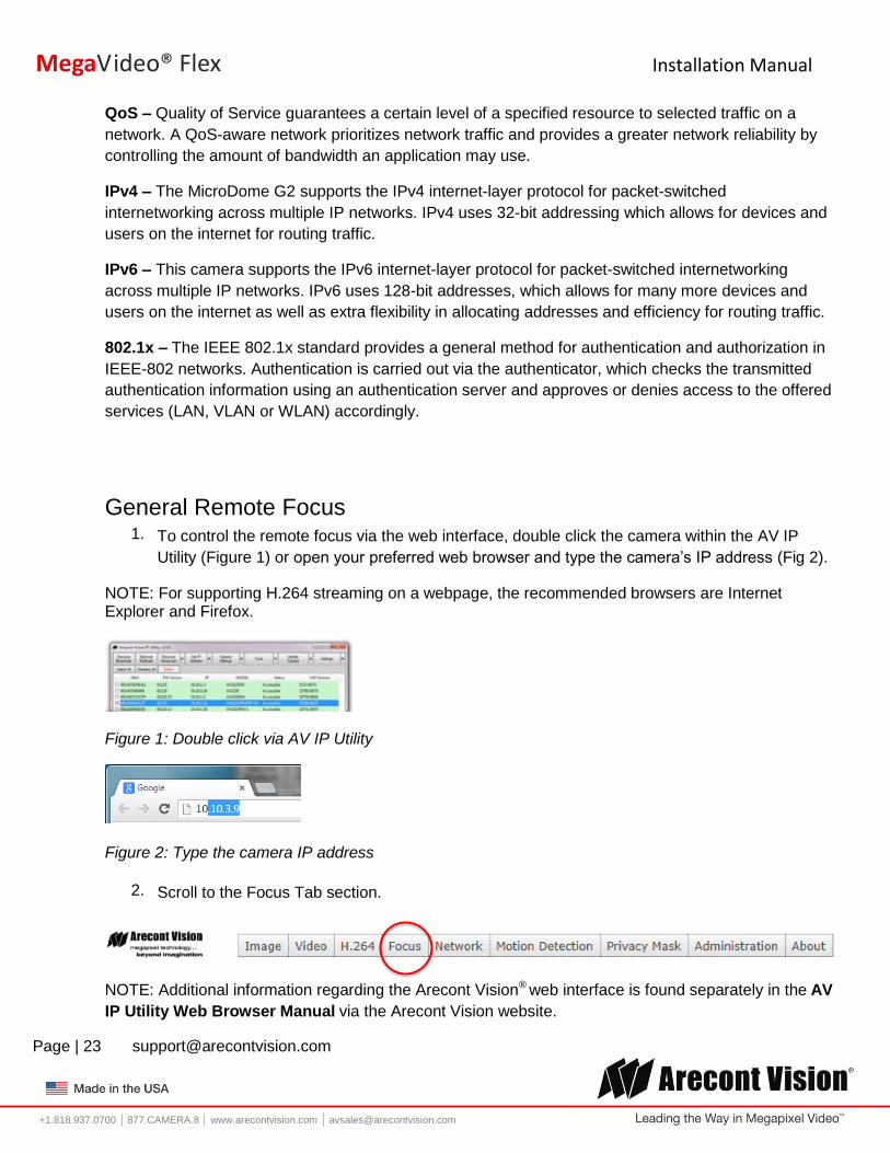
General Remote Focus 1. To control the remote focus via the web interface, double click the camera within the AV IP
Utility (Figure 1) or open your preferred web browser and type the camera’s IP address (Fig 2).
NOTE: For supporting H.264 streaming on a webpage, the recommended browsers are Internet Explorer and Firefox.
Figure 1: Double click via AV IP Utility
Figure 2: Type the camera IP address
2. Scroll to the Focus Tab section.
NOTE: Additional information regarding the Arecont Vision® web interface is found separately in the AV
IP Utility Web Browser Manual via the Arecont Vision website.

Installation Manual
Page | 24 [email protected]
+1.818.937.0700 877.CAMERA.8 www.arecontvision.com [email protected]
MegaVideo® Flex
3. Click the Full-range Focus button. The camera begins to autofocus with the lens stopping at the best overall point of focus. When the focus area turns to Green, the autofocus is complete.
Refined Remote Focus 1. For a more refined, detailed focus, scroll to the Video Tab section and select the PTZ radial
button.
2. Choose an area that has a lot of objects or an area you have an interest in seeing more details. Left click and drag the box to the area where you want to see finer details. The image zooms in.
3. Repeat until you are able to see pixelization of the image as shown below.
4. Select the radial Focus Window option.
Installation Manual
Page | 25 [email protected]
+1.818.937.0700 877.CAMERA.8 www.arecontvision.com [email protected]
MegaVideo® Flex
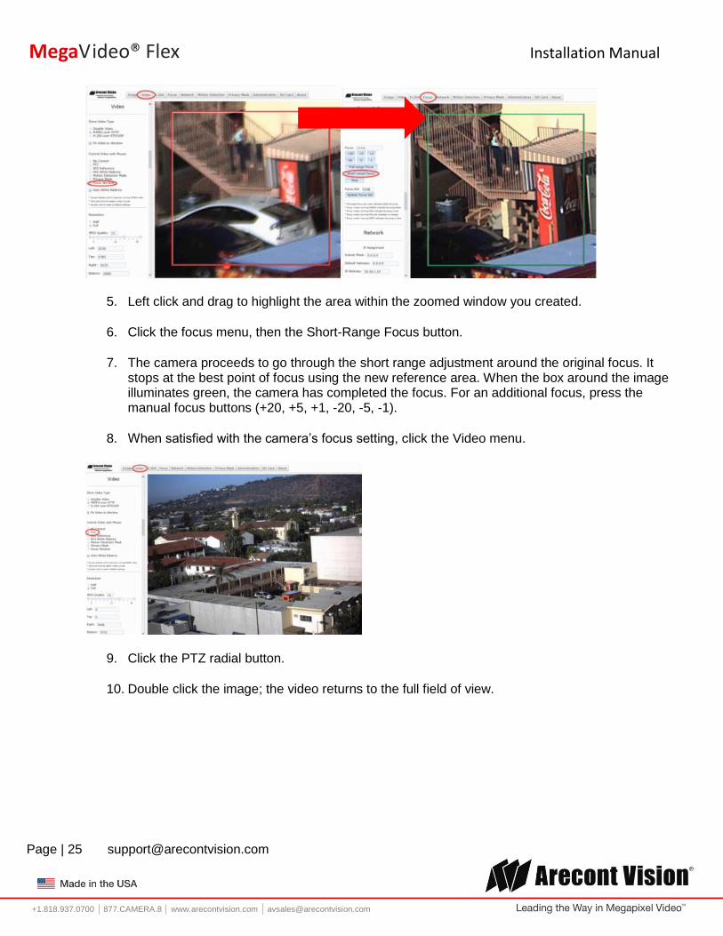
5. Left click and drag to highlight the area within the zoomed window you created.
6. Click the focus menu, then the Short-Range Focus button.
7. The camera proceeds to go through the short range adjustment around the original focus. It stops at the best point of focus using the new reference area. When the box around the image illuminates green, the camera has completed the focus. For an additional focus, press the manual focus buttons (+20, +5, +1, -20, -5, -1).
8. When satisfied with the camera’s focus setting, click the Video menu.
9. Click the PTZ radial button.
10. Double click the image; the video returns to the full field of view.
Installation Manual
Page | 26 [email protected]
+1.818.937.0700 877.CAMERA.8 www.arecontvision.com [email protected]
MegaVideo® Flex
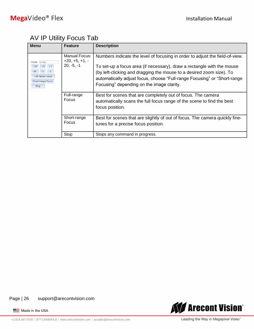
AV IP Utility Focus Tab Menu Feature Description
Manual Focus: +20, +5, +1, -20, -5, -1
Numbers indicate the level of focusing in order to adjust the field-of-view.
To set-up a focus area (if necessary), draw a rectangle with the mouse
(by left-clicking and dragging the mouse to a desired zoom size). To
automatically adjust focus, choose “Full-range Focusing” or “Short-range
Focusing” depending on the image clarity.
Full-range Focus
Best for scenes that are completely out of focus. The camera
automatically scans the full focus range of the scene to find the best
focus position.
Short-range Focus
Best for scenes that are slightly of out of focus. The camera quickly fine-
tunes for a precise focus position.
Stop Stops any command in progress.

Installation Manual
Page | 27 [email protected]
+1.818.937.0700 877.CAMERA.8 www.arecontvision.com [email protected]
MegaVideo® Flex
Mounting Templates
mm/inches

Installation Manual
Page | 28 [email protected]
+1.818.937.0700 877.CAMERA.8 www.arecontvision.com [email protected]
MegaVideo® Flex
mm/inches

Installation Manual
Page | 29 [email protected]
+1.818.937.0700 877.CAMERA.8 www.arecontvision.com [email protected]
MegaVideo® Flex
Support 1. Arecont Vision FAQ Page Located at ArecontVision.com
2. Check the following before you call:
Restore camera to factory default with AV200 or the camera webpage.
Upgrade to the latest firmware by visiting ArecontVision.com.
Isolate the camera on a dedicated network and test with AV200.
Swap the “troubled” camera with a known good camera to see if the problem follows the
camera or stays at the location.
3. Contact Arecont Vision Technical Support one of three ways:
1. Online Portal: Support.ArecontVision.com
2. Phone: 1.818.937.0700 (option #1)
3. Email: [email protected]
4. Use the Arecont Vision software AV IP Utility located on the CD or available for download at our
website (www.arecontvision.com) for camera discovery and setup (see Instruction Manual
located on the CD or available on our website).