Embed Size (px)
Citation preview

MegaPowerTM 48+
System Programming and Operation Manual

2
MegaPowerTM 48+
FCC ComplianceThis equipment has been tested and found to comply with the limits for a Class A digital device, pursuant to Part 15 of theFCC Rules. These limits are designed to provide reasonable protection against interference when the equipment is operatedin a commercial environment. The equipment generates, uses, and can radiate radio frequency energy and, if not installedand used in accordance with the instruction manual, may cause interference to radio communications.
Operation of this equipment in a residential area may cause interference in which case the user will be required to correct theinterference at his own expense.
Equipment Modification CautionEquipment changes or modifications not expressly approved by American Dynamics Video Products Division, the partyresponsible for FCC compliance, could void the user’s authority to operate the equipment, and could create a hazardouscondition.
Warranty DisclaimerAmerican Dynamics Video Products Division makes no representation or warranty of the contents of this manual and disclaimsany implied warranties of merchantability or fitness. American Dynamics Video Products Division reserves the right to revisethis manual and change its content without obligation to notify any person of these revisions.
Software License AgreementA Software License Agreement appears in Appendix E of this manual. Please read it carefully. Using the MegaPower 48+embedded system software indicates that you accept the terms and conditions of this agreement.
DO NOT INSTALL THIS PRODUCT IN HAZARDOUS AREAS WHERE HIGHLY COMBUSTIBLE OREXPLOSIVE PRODUCTS ARE STORED OR USED
3
System Programming and Operation Manual
ContentsFCC Compliance ............................................................................................................................................................................. 2
Equipment Modification Caution ................................................................................................................................................... 2
Warranty Disclaimer ....................................................................................................................................................................... 2
Software License Agreement ......................................................................................................................................................... 2
Introduction ..................................................................................................................................................................................... 5
System Keyboards ...................................................................................................................................................................... 5
System Monitor On-Screen Displays .......................................................................................................................................... 5
Basic User Tasks ............................................................................................................................................................................ 6
Keyboard Access Control ........................................................................................................................................................... 6
Logging on to the Keyboard: Mode 1 .......................................................................................................................................... 6
Logging on to the Keyboard: Mode 2 .......................................................................................................................................... 6
Logging on to the Keyboard: Mode 3 .......................................................................................................................................... 6
Configuring for MP48 or AD1024 mode ...................................................................................................................................... 6
Selecting Monitors ...................................................................................................................................................................... 6
Calling a Camera to View on a Monitor ...................................................................................................................................... 6
Controlling Camera Pan, Tilt and Zoom...................................................................................................................................... 7
Locking and Unlocking a Camera ............................................................................................................................................... 7
Controlling Camera Focus .......................................................................................................................................................... 7
Controlling the Camera Iris ......................................................................................................................................................... 7
Controlling Camera Flip .............................................................................................................................................................. 7
Auto Iris ....................................................................................................................................................................................... 7
Calling Presets (Shots) ............................................................................................................................................................... 7
Running System Tours ................................................................................................................................................................ 8
Holding a Tour ....................................................................................................................................................................... 8
Restarting a Tour on Hold ..................................................................................................................................................... 8
Stepping through a Tour ........................................................................................................................................................ 8
Reversing a Tour ................................................................................................................................................................... 8
Stopping a Tour ..................................................................................................................................................................... 8
Calling a Scratch Pad Tour ......................................................................................................................................................... 8
Calling Salvos ............................................................................................................................................................................. 8
Auxiliary Control .......................................................................................................................................................................... 8
Acknowledging Alarms ................................................................................................................................................................ 8
Running Patterns ........................................................................................................................................................................ 9
Selecting and Running a Macro .................................................................................................................................................. 9
Selecting Video Recorders ......................................................................................................................................................... 9
Advanced User Tasks ................................................................................................................................................................... 10
System Reset ........................................................................................................................................................................... 10
System Data Transfer ............................................................................................................................................................... 10
Setting the Date Format ............................................................................................................................................................ 10
Monitor Display Positioning ...................................................................................................................................................... 10
Setting Presets ......................................................................................................................................................................... 10
Setting Scratch Pad Tours ........................................................................................................................................................ 10
Programming Patterns ............................................................................................................................................................... 11
Arming a Monitor ....................................................................................................................................................................... 11
Disarming a Monitor ................................................................................................................................................................... 11
Programming Macros ................................................................................................................................................................ 11
Stage 1 - Programming the Macro Page and Icon .............................................................................................................. 11
Stage 2 - Programming a Macro ......................................................................................................................................... 12
Advanced Macros ............................................................................................................................................................... 13
Programming Smart Cards ....................................................................................................................................................... 13
Copying Macro Information From One Smart Card To Another ............................................................................................... 14
Configuring Partitions ............................................................................................................................................................... 14
4
MegaPowerTM 48+
Menu Programming ...................................................................................................................................................................... 15
Accessing Menus ...................................................................................................................................................................... 15
Menu Controls .......................................................................................................................................................................... 15
Main Selection Menu ................................................................................................................................................................ 16
System Menu ............................................................................................................................................................................ 16
System Options .................................................................................................................................................................. 16
Time and Date .................................................................................................................................................................... 17
Ports .................................................................................................................................................................................... 18
Monitor Status ..................................................................................................................................................................... 18
Paging Profile ..................................................................................................................................................................... 19
Multi-Matrix ......................................................................................................................................................................... 20
Monitor Menu ............................................................................................................................................................................ 22
Cameras Menu ......................................................................................................................................................................... 24
Assign Pseudo Cameras .................................................................................................................................................... 24
Camera Titles ...................................................................................................................................................................... 24
Preset Titles ........................................................................................................................................................................ 25
Preset/Preset Title Numbers ............................................................................................................................................... 25
Dome Status ....................................................................................................................................................................... 25
Dome Ping .......................................................................................................................................................................... 26
Users/Keyboard Menu .............................................................................................................................................................. 26
User .................................................................................................................................................................................... 26
Keyboard ............................................................................................................................................................................. 27
Priority ................................................................................................................................................................................. 27
Switching Menu ......................................................................................................................................................................... 28
System Tours ...................................................................................................................................................................... 28
System Salvos .................................................................................................................................................................... 29
Event Timers ....................................................................................................................................................................... 30
Partitioning Menu ...................................................................................................................................................................... 31
Keyboard/Monitor ............................................................................................................................................................... 31
Keyboard/Camera View ...................................................................................................................................................... 32
Keyboard/Camera Control .................................................................................................................................................. 32
Monitor/Camera Access ..................................................................................................................................................... 33
Alarms ....................................................................................................................................................................................... 34
Programming an Alarm ....................................................................................................................................................... 34
Additional Alarm Programming Notes ................................................................................................................................. 34
Alarms Menu ............................................................................................................................................................................. 35
Alarm Messages ................................................................................................................................................................. 35
Alarm Setup ........................................................................................................................................................................ 35
Associate Alarms to Monitors ............................................................................................................................................. 38
Appendix A: Special Function Key Commands ......................................................................................................................... 40
Appendix B: SpeedDome Series Programmable Commands .................................................................................................. 41
Appendix C: Printer Messages .................................................................................................................................................... 42
Appendix D: Monitor Identification Numbers ............................................................................................................................ 43
Appendix E: Software License Agreement ................................................................................................................................. 44
5
System Programming and Operation Manual
IntroductionMegaPower 48+ is a matrix switcher/controller systemwith a broad range of functionality. System featuresinclude:
• Matrix size of 48 video inputs by 16 video outputs
• Matrices can be connected together to extend thesystem to a maximum size of 288 cameras with 8 fullcross point switched monitor outputs and 7 additionalmonitor outputs on each secondary matrix (for viewingof video from that secondary matrix only).
• Eight primary video outputs with text overlay. Textoverlay on all secondary monitors.
• Modular wall mount with rack mount option
• Embedded menus for system setup programming
• Flash memory module on system for data backup
• Video recorder control through keyboard (withcompatible keyboards)
• Macro programming and control through keyboard(with compatible keyboards)
• Fixed and variable speed pan/tilt and dome controlusing SensorNet, SEC-RS422 or AD Manchesterprotocols
• Alarm responses include camera, presets, patterns,salvos, text paging, recorder and auxiliary control
• Text paging on alarm. Up to 250 different messages
• System partitioning for inputs, outputs and keyboards
• System priority levels and user passwords
• Monitor tours
• On-screen text includes video input number, monitorstatus, time/date and camera, preset and alarm titles
• 64 universal tours
• 64 system salvos
• 35 event timers
• Alarm tables for four categories
• Automatic call up of alarm inputs
• 4096 preset titles
• 250 alarm messages
• On board system diagnostics
System KeyboardsOperation and programming of MegaPower 48+ isaccomplished through commands entered on a systemkeyboard. AD system keyboards available includeADCC1100, ADCC0200, ADCC0300 and ADTTE TouchTrackers®.
The basic operating procedures for each of thesekeyboards are virtually identical. Access to different taskand programming levels is controlled by using smart cardson the ADCC1100 and passcodes on the ADCC0200 andADCC0300. On the ADTTE, access is determined by akey-controlled “system lock” and password procedure.
Because the ADCC1100 provides the most extensivefeature set of the currently available keyboards,MegaPower 48+ operation and programming will bediscussed with reference to the ADCC1100 keyboardlayout.
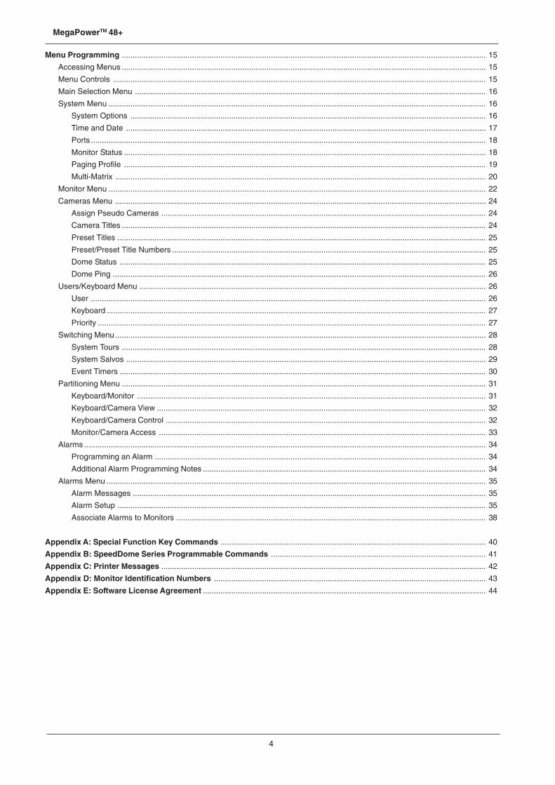
System Monitor On-Screen DisplaysWhen an operator calls a camera to view on primarymatrix monitors 1-8 and on any monitors connected tosecondary matrices, a text overlay appears on theselected video. The MegaPower 48+ system provides twodifferent formats for on-screen display. See page 23 fordetails on setting the display format for system monitors.
When Format 1 is selected, five fields of information aredisplayed at the bottom of the screen:
• The Camera Number can be a real or pseudo numberranging in value from 1 to 9999.
• The Status Line shows current information aboutsystem operation. Status information includes day ofthe week and monitor arming codes, dwell times, andmessages related to tours, salvos, and alarms.
• The Camera Title consists of two lines of up to eightcharacters for each line. See page 24 for details onsetting camera titles.
• The current Date can be provided in one of threedifferent formats. See page 17 for details on settingthe date.
• The current Time is provided in 24 hour format. Seepage 17 for details on setting the time.
When Format 2 is selected, the time and date fieldsappear at the top of the screen. Camera number, statusand camera title appear on the bottom of the screen.
6
MegaPowerTM 48+
Basic User Tasks(using an ADCC1100 keyboard)
This section discusses how a keyboard operator gainsaccess to a MegaPower 48+ system, and how camerasare called to view on workstation monitors.
Control of pan/tilt cameras is discussed, and how to zoom,focus, and adjust the iris of a camera lens. The sectionalso discusses how to run tours, patterns, and macros,and how to call presets and salvos.
There is also an explanation of how to select and controla VCR. In addition, procedures are provided foracknowledging alarms and controlling auxiliary devices.
Most of the operations discussed in this section can beperformed on the ADCC0200, ADCC0300, AD2079,AD2088 and ADTTE Touch Tracker keyboards. Consultthe documentation provided with the keyboard for moredetails.
Keyboard Access ControlUser access to the ADCC1100 depends on whether theUser IDs feature has been enabled on the connectedMegaPower 48+ matrix (see page 16). There are threemodes of user access control:
Mode 1User access is controlled by the smart card only. If UserIDs are disabled on the MegaPower 48+, then thekeyboard will log on to the matrix as soon as the smartcard is inserted into the keyboard.
Mode 2User access is controlled by a matrix User ID (which isstored on the smart card) and by a PIN number. If UserIDs are enabled on the switching matrix the keyboard willcheck the smart card to see if the User ID has been storedon the card. If it has, the operator only needs to enter aPIN number.
Mode 3User access is controlled by a matrix User ID (which isnot stored on the smart card) and by a PIN number. If noUser ID has been stored on the smart card, the keyboardwill prompt the user to enter the User ID and then the PINnumber.
For user number 1, the system is provided with a defaultsix-digit passcode “914365”. This default passcodeshould be changed to guard against unauthorizedaccess to the system. To insure system security, allpasscode information should be kept confidential.
Logging on to the Keyboard: Mode 11. At the welcome screen insert the smart card.
2. Depending on the privileges of the operator(supervisor, administrator or operator) a version ofthe main menu will be displayed.
Logging on to the Keyboard: Mode 21. At the welcome screen insert the smart card.
2. At the Enter PIN screen, enter the PIN number usingthe alphanumeric keys. Press the ENTER soft key.
3. Depending on the privileges of the operator(supervisor, administrator or operator) a version ofthe main menu will be displayed.
Logging on to the Keyboard: Mode 31. At the welcome screen insert the smart card.
2. At the Enter User ID screen, enter the User ID numberusing the alphanumeric keys. Press the ENTER soft key.
3. At the Enter PIN screen, enter the PIN number usingthe alphanumeric keys. Press the ENTER soft key.
4. Depending on the privileges of the operator(supervisor, administrator or operator) a version ofthe main menu will be displayed.
Configuring for MP48 or AD1024 modeThe ADCC1100 keyboard is designed for use with theMegaPower 48+ or AD1024 matrix switching system. TheADCC1100 keyboard needs to be set to one of thesesystems in order to operate correctly.
1. Using the Administrator’s smart card, log on to thesystem.
2. Press the PROGRAM MODE tab key.
3. Press the NEXT soft key.
4. Press the MP48 MODE/AD1024 MODE soft key. Thishas a toggle action selecting either MP48 Mode orAD1024 Mode.
5. Remove the Administrator’s smart card.
The keyboard is now set to the selected mode and willretain this setting—even after powering off the keyboard—until it is changed again using the steps above.
Selecting MonitorsWorkstation monitors display the video from the camerasand domes installed in local and/or satellite facilities. Eachmonitor has an identification number documented by thesystem administrator.
To select a monitor:
1. Enter the monitor identification number on the numerickeypad. The number entered will appear next to theENTER caption on the display.
2. Press the MONITOR button. The monitor number willdisappear from next to the ENTER caption and appearbeneath the MONITOR caption on the display.
Note: video output X16 (primary matrix, output port 16)can be used by the system to sample video. If video lossdetection is enabled for any system video input, X16 willnot be available for video switching.
Calling a Camera to View on a MonitorAfter a monitor has been called to the control of thekeyboard, a camera can be called to view on the monitor.Each system camera has a unique identification numberdocumented by the system administrator.
To call a camera:
1. Enter the camera identification number on the numerickeypad. The number entered will appear next to theENTER caption on the display.
2. Press the CAMERA button. The camera number willdisappear from next to the ENTER caption and appearbeneath the CAMERA caption on the display.
The selected video input now appears on the monitorscreen. After calling a camera to the selected monitor,any other camera can be called to the monitor byrepeating the two-step procedure described above.

7
System Programming and Operation Manual
Notes• Monitors connected to secondary matrices can only
view cameras connected to that secondary unit. Ifvideo from a secondary matrix is called to be viewedon a monitor connected to another matrix, a messagewill be displayed on-screen informing the user thatthe video input is invalid.
• On-screen text display is available on primary matrixmonitors 1-8 and also on any monitors connected tosecondary matrices.
Controlling Camera Pan, Tilt and ZoomOnce an appropriately equipped camera has been calledto view on a monitor, the operator can manually controlthe camera's movement. Pan is the side-to-sidemovement of the camera. Tilt is the up and downmovement of the camera.
The keyboard's joystick controls the panning and tiltingof cameras connected to the switching matrix. As thejoystick is moved to the left or right, and is moved towardsor away from the operator, the camera will pan and/or tiltaccordingly.
For cameras with variable speed pan/tilt capability,camera movement speed is proportional to the positioningof the joystick. The further from the stationary centreposition the joystick travels, the faster the camera willmove.
Zoom refers to the apparent action of moving closer to orfarther away from an object, as seen through the cameralens. For cameras equipped with an appropriate zoomlens, the zoom function can be controlled from the joystickby twisting it clockwise or counterclockwise. Twistingclockwise enables the lens to zoom in. Twistingcounterclockwise enables the lens to zoom out.
Center the joystick when the camera has been positionedappropriately.
Locking and Unlocking a CameraAfter calling a pan/tilt camera to view and control on asystem monitor, an operator can prevent other operatorsfrom controlling the movements of the called camera. Thisis referred to as “locking” the camera.
To lock a camera:
1. Enter the camera identification number on thealphanumeric keypad.
2. Press the CAMERA button.
3. Press the OPERATOR tab key, then the NEXT softkey.
4. Press the LOCK CAMERA ( ) soft key. The LOCKCAMERA key’s icon will change to UNLOCK CAMERA
( ).
To unlock a camera:
1. Enter the camera identification number on thealphanumeric keypad.
2. Press the CAMERA button.
3. Press the OPERATOR tab key, then the NEXT softkey.
4. Press the UNLOCK CAMERA ( ) soft key. TheUNLOCK CAMERA key's icon will change to LOCK
CAMERA ( ).
Controlling Camera FocusFocus refers to the action of adjusting the clarity of thecamera image displayed on the monitor. To focus thecamera on a distant object, press the FAR key ( ). Tofocus on a closer object, press the NEAR key ( ).
Controlling the Camera IrisNormally, the brightness of a picture is controlled by thecamera’s auto gain and the auto/manual iris functions.However, there may be times when you would like thepicture on the monitor to appear darker or lighter. Tobrighten the picture, press the iris OPEN key ( ). Todarken the picture, press the iris CLOSE key ( ).
Controlling Camera FlipTo “flip” the camera under keyboard control 180O from itscurrent position (for uninterrupted surveillance of objectswhich pass directly beneath the camera), use the flip softkey.
To flip the camera:
1. Press the OPERATOR tab key.
2. Press the NEXT soft key.
3. Press the FLIP soft key.
Note: on suitably equipped domes with the auto-flipfunction turned on, the dome flips automatically when thesubject passes directly beneath the camera.
Auto IrisCertain cameras are designed with Auto Iris capability.The feature can be enabled from the keyboard as follows.
To enable auto iris:
1. Press the OPERATOR tab key.
2. Press the NEXT soft key.
3. Press the AUTO IRIS soft key.
Note: using the manual OPEN or CLOSE iris key willoverride the Auto Iris function as long as either of thesekeys is held down. The camera may or may not then returnto auto iris mode after a time interval, or it may stay inmanual iris mode. This depends on the camera undercontrol and how the camera has been set up.
Calling Presets (Shots)A preset is a memorized location or scene that a pan/tiltcamera can display on operator demand. Presets are alsoreferred to as shots or targets. In the MegaPower 48+system, an operator can call up to 96 presets per camera(depending on the receiver/driver wired to the camera),with a total of 4096 presets allowed. Presets arepositioned and stored in memory in the Program mode.
To call a preset:
1. After calling a pan/tilt camera to view, enter the presetidentification number using the alphanumeric keys.The number entered will appear next to the ENTERcaption.
2. Press the PRESET ( ) soft key.
3. The PRESET n caption will appear on the display(where n is the preset identification number enteredin step 1 above.
8
MegaPowerTM 48+
Running System ToursA tour is a dynamic sequence of camera views, each ofwhich appears on a selected monitor screen for aspecified dwell time, and each of which can have a pre-programmed preset status, auxiliary status, and connectnext designation. System tours are also referred to asuniversal tours.
Additionally, there are monitor or “scratch-pad” tours,which are temporary tours programmed for the operator’scurrently selected monitor.
To run a system (universal) tour:
1. Select a monitor.
2. Enter the system tour identification number using thealphanumeric keys. The number entered will appearnext to the ENTER caption.
3. Press the RUN soft key.
4. The TOUR MODE n caption will appear on the display(where n is the system tour identification numberentered in step 2 above.
Note: after the RUN soft key is pressed, its captionchanges to HOLD—see Holding a Tour below.
When running a tour in the forward direction, an “F” isdisplayed on the on-screen status line next to the dwelltime. When a tour is running in the reverse direction, an“R” is displayed on the screen.
Holding a TourA tour can be stopped and held on a single camera entryby pressing the HOLD soft key. While a tour is on hold,all keyboard control actions (pan, tilt, lens adjustment,auxiliary on/off functions) can be performed on the heldcamera.
Note: after the HOLD soft key is pressed, its captionchanges to RUN—see Restarting a Tour on Hold below.
Restarting a Tour on HoldTo restart a held tour, press the RUN soft key. The tourwill continue running from the point at which it waspreviously held.
Stepping through a TourWhen a tour is running, the INCREMENT/ DECREMENTCAMERA keys can be used to step through the tour.
To step through a tour:
1. To step forward press the ▲ key.
2. To step backward, press the ▼ key.
Reversing a TourWhen a tour is running, the INCREMENT / DECREMENTCAMERA keys can be used to reverse the direction of atour.
To reverse the direction of a tour:
1. Press the ▼ key once. Note, to again reverse the tour,press the ▲ key once.
Stopping a TourA running system or scratch-pad tour can be stopped byeither pressing the HOLD soft key, or by calling a camerato view on the selected monitor.
Calling a Scratch Pad TourEach monitor can have a stored scratch-pad tour (atemporary tour programmed by the operator).
To call a scratch-pad tour:
1. Select the monitor for the desired scratch-pad tour(ensure that there is no tour currently running on theselected monitor).
2. Press the RUN soft key.
Calling SalvosA salvo is the simultaneous display of multiple camerascenes on a group of numerically contiguous monitors.The MegaPower 48+ system allows 64 salvos with up to16 entries per salvo. Each system salvo has a uniqueidentification number that defines the set of contiguousmonitors.
To call a salvo:
1. Enter the identification number of the first (lowestnumbered) monitor of the contiguous monitor groupon the alphanumeric keypad. The monitor numberentered will appear next to ENTER on the keyboard’sdisplay.
2. Press the MONITOR key.
3. Enter the identification number for the salvo. Thenumber entered will appear next to ENTER on thekeyboard’s display.
4. Press the SALVO soft key.
Auxiliary ControlAn auxiliary is a relay that switches devices such ascamera lights, a camera washer, and a camera wiper, onor off. The ADCC1100 keyboard can control fourauxiliaries labelled AUX 1, AUX 2, AUX 3, and AUX 4.AUX 1 and AUX 2 are on the first operator screen, AUX 3and AUX 4 are on the second operator screen. Soft keysare used to turn the auxiliary function ON or OFF. Theauxiliary function will remain ON until the soft key is againpressed.
An auxiliary that is set to ON will be shown by its keyboardicon in inverse video. The keyboard always sets auxiliaryfunctions to OFF when a new camera is selected.
Acknowledging AlarmsWhen a monitor is armed for alarm display, the videoinput associated with the appropriate alarm contact isdisplayed on the monitor when the alarm is activated. Ifthe monitor is armed for manual clearance, any alarmdisplayed on the monitor can be acknowledged (cleared)by a keyboard operator.
To acknowledge an alarm:
1. Call the monitor that is displaying the alarm video.
2. Press the ALARM ( ) soft key.
If the monitor is sequencing multiple alarms, step throughto the appropriate alarmed video input by first pressingthe RUN/HOLD soft key and then by using theINCREMENT/ DECREMENT CAMERA key. Press theALARM soft key to acknowledge the alarm. Continue tostep to and acknowledge each alarm until all theappropriate alarms have been cleared.
9
System Programming and Operation Manual
Running PatternsA pattern is a sequential series of pan, tilt, zoom, andfocus commands defined for SpeedDome series domes.A pattern is programmed in real time, which means thatthe dome remembers each pattern segment in the actualtime it takes the operator to execute a command. Forexample, if, during a pattern sequence, the dome focuseson a door for 30 seconds, the door scene will appear for30 seconds when the pattern is called to run.
To run a pattern:
1. Press the OPERATOR tab key.
2. Call the camera that the pattern will run on.
3. Enter the pattern number (1-3) using the alphanumerickeys. The pattern number will appear next to ENTERon the keyboard’s display.
4. Press the PATTERN soft key.
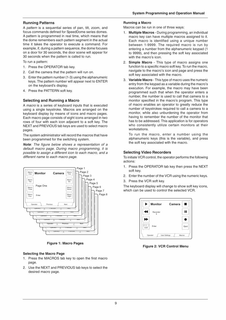
Selecting and Running a MacroA macro is a series of keyboard inputs that is executedusing a single keystroke. Macros are arranged on thekeyboard display by means of icons and macro pages.Each macro page consists of eight icons arranged in tworows of four with each icon adjacent to a soft key. TheNEXT and PREVIOUS tab keys are used to select macropages.
The system administrator will record the macros that havebeen programmed for the switching system.
Note: The figure below shows a representation of adefault macro page. During macro programming, it ispossible to assign a different icon to each macro, and adifferent name to each macro page.
Figure 1: Macro Pages
Selecting the Macro Page1. Press the MACROS tab key to open the first macro
page.
2. Use the NEXT and PREVIOUS tab keys to select thedesired macro page.
Running a MacroMacros can be run in one of three ways:
1. Multiple Macros - During programming, an individualmacro key can have multiple macros assigned to it.Each macro is identified using a unique numberbetween 1-9999. The required macro is run byentering a number from the alphanumeric keypad (1to 9999), and then pressing the soft key associatedwith the macro’s icon.
2. Simple Macro - This type of macro assigns onefunction to a specific macro soft key. To run the macro,navigate to the macro’s icon and page and press thesoft key associated with the macro.
3. Variable Macro - This type of macro uses the numericentry from the keypad as a variable during the macro’sexecution. For example, the macro may have beenprogrammed such that when the operator enters anumber, the number is used to call that camera to amonitor specified in the macro’s program. This typeof macro enables an operator to greatly reduce thenumber of keystrokes required to call a camera to amonitor, while also unburdening the operator fromhaving to remember the number of the monitor thathas to be addressed. This application is for operatorswho consistently utilize certain monitors at theirworkstations.
To run the macro, enter a number using thealphanumeric keys (this is the variable), and pressthe soft key associated with the macro.
Selecting Video RecordersTo initiate VCR control, the operator performs the followingactions:
1. Press the OPERATOR tab key then press the NEXTsoft key.
2. Enter the number of the VCR using the numeric keys.
3. Press the VCR soft key.
The keyboard display will change to show soft key icons,which can be used to control the selected VCR.
Figure 2: VCR Control Menu
10
MegaPowerTM 48+
Advanced User Tasks(using an ADCC1100 keyboard)
This section provides step-by-step instructions for moreadvanced keyboard operations such as programmingpresets, scratch-pad tours, patterns, and macros.
System ResetTo clear all previously programmed information and resetthe MegaPower 48+ system to its original default settings,a system reset can be performed.
Note: In order for a system reset to be performed, systemreset must be enabled when defining a user or keyboard’spriority level. For more details, see page 27.
To perform a system reset:
1. Press the PROGRAM MODE tab key.
2. Enter “55” on the numeric keypad.
3. Press the keyboard’s F2 soft key. Enter the followingkeypad/F2 combination within three seconds.
4. “99” F2. If step 4 is not performed within the requiredthree-second interval, the system will not reset.
System Data TransferSystem data can be transferred from the MegaPower 48+system to a flash memory module in the patch panelsection of the assembly. Data can also be transferredback to the system from the memory module.
Note: In order for a system data transfer to be performed,system reset must be enabled when defining a user orkeyboard’s priority level. For more details, see page 27.
To perform a data transfer from the system to the memorymodule:
1. Press the PROGRAM MODE tab key.
2. Enter “55” on the numeric keypad.
3. Press the keyboard’s F2 soft key. Enter the followingkeypad/F2 combination within three seconds.
4. “140” F2. If step 4 is not performed within the requiredthree-second interval, the data transfer will not takeplace.
To perform a data transfer from the memory module tothe system:
1. Press the PROGRAM MODE tab key.
2. Enter “55” on the numeric keypad.
3. Press the keyboard’s F2 soft key. Enter the followingkeypad/F2 combination within three seconds.
4. “141” F2. If step 4 is not performed within the requiredthree-second interval, the data transfer will not takeplace.
Setting the Date FormatThere are three options for the monitor on-screen dateformat. The default date format is MM-DD-YY (month,day, year). To set the date format from the keyboard:
1. Press the PROGRAM MODE tab key.
2. Enter one of the following F2 code combinations:
• “21 F2” for MM-DD-YY
• “22 F2” for DD-MM-YY
• “23 F2” for YY-MM-DD
• “24 F2” toggles through the date formats.
Monitor Display PositioningThe monitor on-screen display text for Format 1 (see page5) can be positioned per user requirements. To adjustthe home positioning of the selected text overlay:
1. Call the appropriate camera to the monitor underkeyboard command.
2. Press the PROGRAM MODE tab key.
3. Enter “50 F2” on the keypad. This enables the joystickto set the home position of the display text.
4. Use the joystick to set the appropriate home positionof the text.
5. Enter “51 F2” on the keypad. This disables the joystickfor text positioning.
Note: the text positioning procedure discussed directlyabove cannot be implemented when the on-screendisplay is set to Format 2.
Setting PresetsDome, and pan/tilt cameras can be programmed with oneor more preset shots.
To program a preset:
1. Call the desired camera to a monitor.
2. Maneuver the camera as required using thekeyboard’s joystick.
3. Select the PROGRAM MODE tab key.
4. Enter a number for the preset using the alphanumerickeys.
5. Press the PRESET ( ) soft key.
Setting Scratch Pad ToursTo set a scratch pad tour:
1. Call a monitor to the keyboard.
2. Press the PROGRAM MODE tab key.
3. Press the KEYB CONFIG soft key.
4. Press the PROG S PAD soft key.
5. Enter a camera number for the first camera in thetour to be called to the monitor. Press the ENTERsoft key.
6. Enter a dwell time for the camera in seconds (1-60).Press the DWELL TIME soft key.
7. Repeat steps 5 and 6 until all the cameras in the tourhave been programmed.
8. Press the OPERATOR tab key to exit the scratch padtour menu.
Note: On monitors connected to secondary units, it isonly possible to recall cameras connected to the samesecondary unit. If a tour is recalled on a secondary monitorand a camera in that tour is not available, the previouscamera view will remain on the monitor for the requireddwell time. A message (“INVcccc”) is displayed on themonitor to indicate that an invalid camera was selected.
11
System Programming and Operation Manual
Programming PatternsYou can program up to three patterns per programmabledome. The length and complexity of a pattern are limitedby two variables:
• number of camera commands• timeEach time you move the camera in any direction (alongwith zoom, focus, and iris adjustments), you are issuinga command to the camera. The three patterns for a domecan collectively consist of up to 98 camera commands.
There is also a pattern time limit. A single pattern cannothave duration longer than 400 seconds. How ever manycommands have been issued, a pattern will stop recordingonce the time limit has elapsed.
Defining Patterns
To define a pattern:
1. Call the desired dome to a monitor.2. Maneuver the camera to the position where the pattern
will start using the keyboard’s joystick.
3. Press the PROGRAM MODE tab key.
4. Press the PROGRAM PATTERN soft key. Thekeyboard display will change to the pattern programmenu.
5. Enter a number (1-3) for the pattern using thealphanumeric keys.
6. Press the PATTERN soft key.
7. Maneuver the camera using the joystick to define thepattern.
8. When the pattern movements have been completed,press the END soft key.
9. Press the PROGRAM MODE tab key to exit the patternprogram menu.
Clearing Patterns
To clear a pattern:
1. Press the PROGRAM MODE tab key.
2. Press the PROGRAM PATTERN soft key. Thekeyboard display will change to the pattern programmenu.
3. Enter the number (1-3) of the pattern to be cleared.
4. Press the CLEAR soft key.
5. Press the PROGRAM MODE tab key to exit the patternprogram menu.
Arming a MonitorWhen a monitor is armed, the video input associated withan alarm for that monitor appears when the alarm hasbeen triggered. To arm a monitor, do the following:
1. Call the monitor to be armed.
2. Press the PROGRAM MODE tab key.
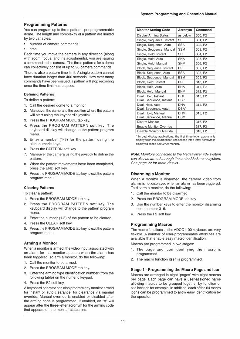
3. Enter the arming type identification number (from thefollowing table) on the numeric keypad.
4. Press the F2 soft key.A keyboard operator can also program any monitor armedfor instant or auto clearance, for clearance via manualoverride. Manual override is enabled or disabled afterthe arming code is programmed. If enabled, an "A" willappear after the three-letter acronym for the arming codethat appears on the monitor status line.
* In dual display applications, the first three-letter acronym isdisplayed on the hold monitor. The second three-letter acronym isdisplayed on the sequence monitor.
Monitor Arming Code Acronym Command
Display Arming Status as below 300, F2
Single, Sequence, Instant SSI 301, F2
Single, Sequence, Auto SSA 302, F2Single, Sequence, Manual SSM 303, F2
Single, Hold, Instant SHI 304, F2
Single, Hold, Auto SHA 305, F2Single, Hold, Manual SHM 306, F2
Block, Sequence, Instant BSI 307, F2
Block, Sequence, Auto BSA 308, F2Block, Sequence, Manual BSM 309, F2
Block, Hold, Instant BHI 310, F2
Block, Hold, Auto BHA 311, F2Block, Hold, Manual BHM 312, F2
Dual, Hold, Instant DHI 313, F2Dual, Sequence, Instant DSI*
Dual, Hold, Auto DHA 314, F2Dual, Sequence, Auto DSA*Dual, Hold, Manual DHM 315, F2Dual, Sequence, Manual DSM*
Disarm Monitor 316, F2
Enable Monitor Override 317, F2Disable Monitor Override 318, F2
Note: Monitors connected to the MegaPower 48+ systemcan also be armed through the embedded menu system.See page 22 for more details.
Disarming a MonitorWhen a monitor is disarmed, the camera video fromalarms is not displayed when an alarm has been triggered.To disarm a monitor, do the following:
1. Call the monitor to be disarmed.
2. Press the PROGRAM MODE tab key.
3. Use the number keys to enter the monitor disarmingcode number 316.
4. Press the F2 soft key.
Programming MacrosThe macro functions on the ADCC1100 keyboard are veryflexible. A number of user-programmable attributes areavailable that enable easy macro identification.
Macros are programmed in two stages:
1. The page and icon identifying the macro isprogrammed.
2. The macro function itself is programmed.
Stage 1 - Programming the Macro Page and IconMacros are arranged in eight “pages” with eight macrosper page. Each page can have a user-assigned nameallowing macros to be grouped together by function orsite location for example. In addition, each of the 64 macroicons can be programmed to allow easy identification bythe operator.
12
MegaPowerTM 48+
It is important to note that during programming, macroprogram information is initially stored using the keyboard’stemporary memory. However, macros may be written toa smart card either operator-by-operator, or as a “mastercollection” of system macros stored on the administrator’ssmart card.
If the smart card is removed from the keyboard beforemacros have been written to it, any programmed macroswill be lost.
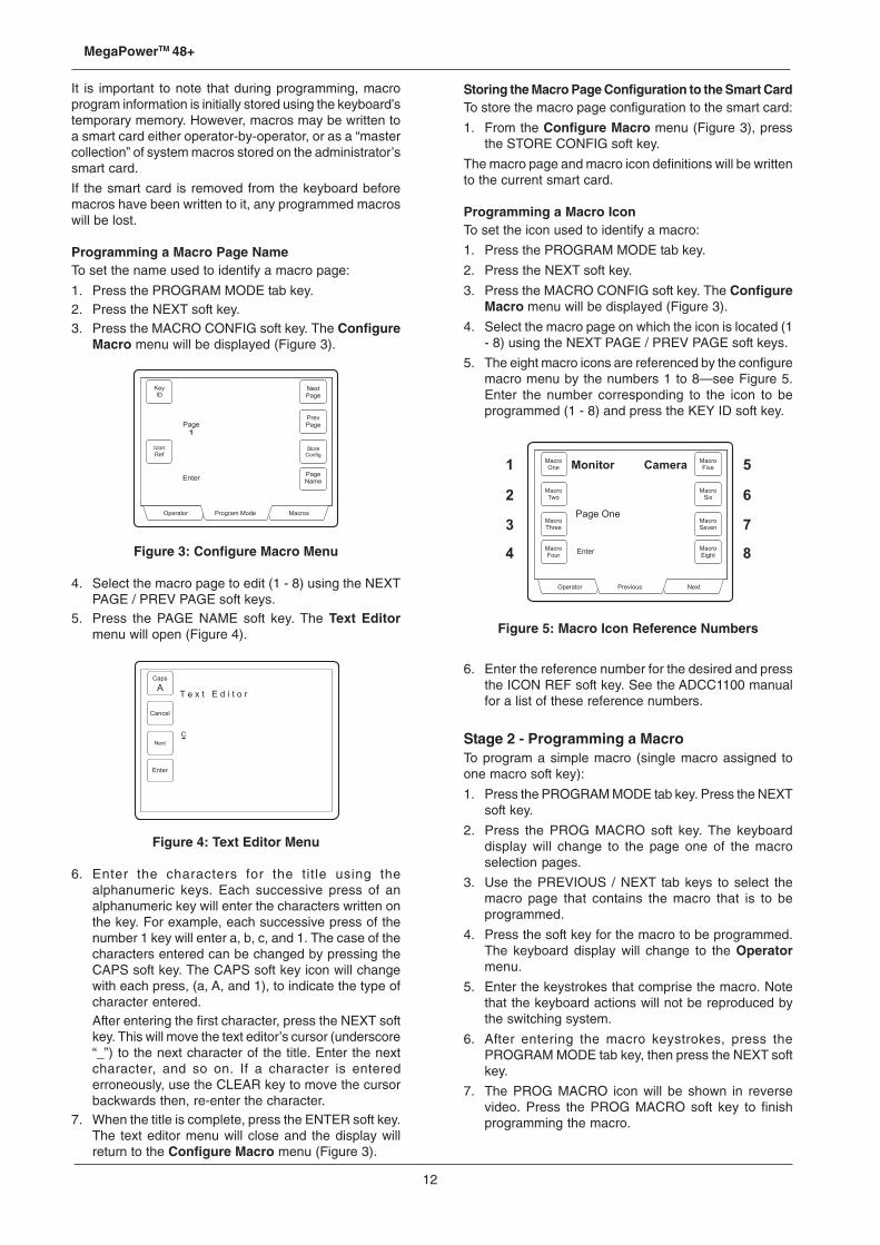
Programming a Macro Page NameTo set the name used to identify a macro page:
1. Press the PROGRAM MODE tab key.2. Press the NEXT soft key.3. Press the MACRO CONFIG soft key. The Configure
Macro menu will be displayed (Figure 3).
Figure 3: Configure Macro Menu
4. Select the macro page to edit (1 - 8) using the NEXTPAGE / PREV PAGE soft keys.
5. Press the PAGE NAME soft key. The Text Editormenu will open (Figure 4).
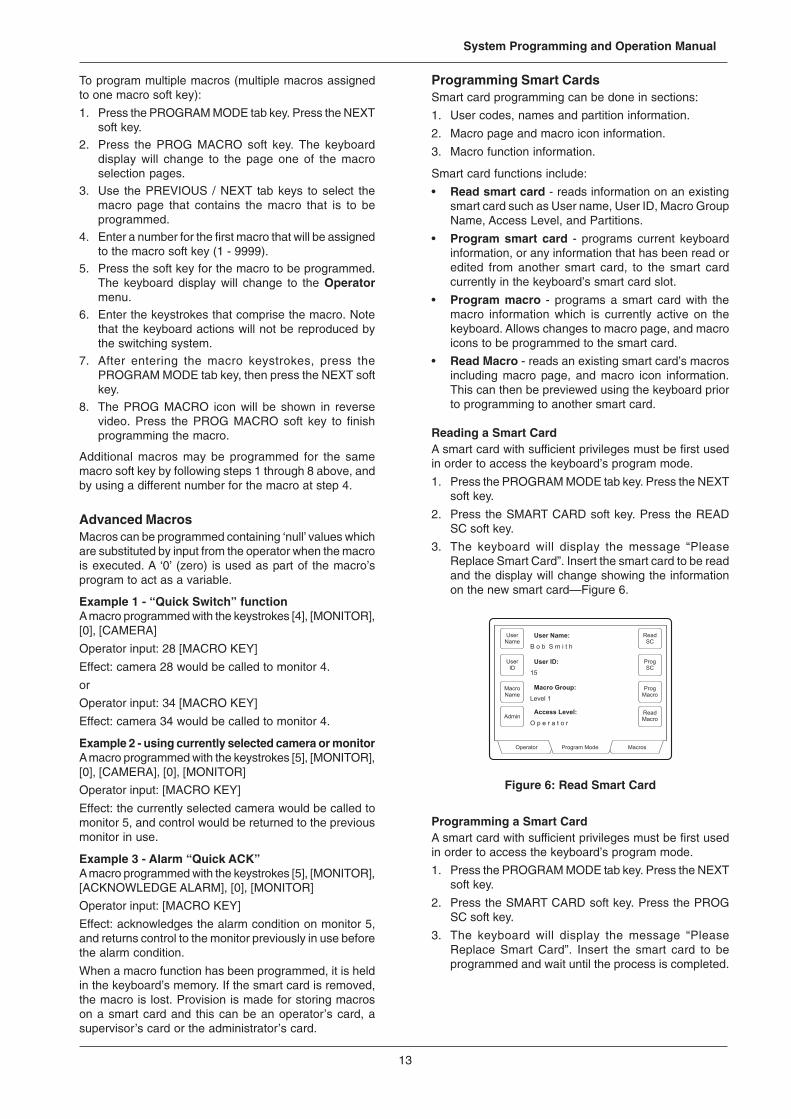
Figure 4: Text Editor Menu
6. Enter the characters for the title using thealphanumeric keys. Each successive press of analphanumeric key will enter the characters written onthe key. For example, each successive press of thenumber 1 key will enter a, b, c, and 1. The case of thecharacters entered can be changed by pressing theCAPS soft key. The CAPS soft key icon will changewith each press, (a, A, and 1), to indicate the type ofcharacter entered.After entering the first character, press the NEXT softkey. This will move the text editor’s cursor (underscore“_”) to the next character of the title. Enter the nextcharacter, and so on. If a character is enterederroneously, use the CLEAR key to move the cursorbackwards then, re-enter the character.
7. When the title is complete, press the ENTER soft key.The text editor menu will close and the display willreturn to the Configure Macro menu (Figure 3).
Storing the Macro Page Configuration to the Smart CardTo store the macro page configuration to the smart card:
1. From the Configure Macro menu (Figure 3), pressthe STORE CONFIG soft key.
The macro page and macro icon definitions will be writtento the current smart card.
Programming a Macro IconTo set the icon used to identify a macro:
1. Press the PROGRAM MODE tab key.
2. Press the NEXT soft key.
3. Press the MACRO CONFIG soft key. The ConfigureMacro menu will be displayed (Figure 3).
4. Select the macro page on which the icon is located (1- 8) using the NEXT PAGE / PREV PAGE soft keys.
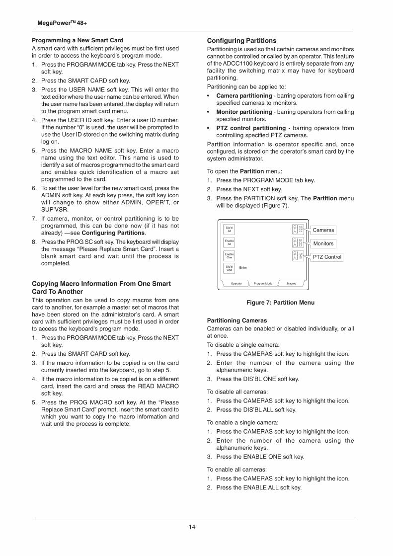
5. The eight macro icons are referenced by the configuremacro menu by the numbers 1 to 8—see Figure 5.Enter the number corresponding to the icon to beprogrammed (1 - 8) and press the KEY ID soft key.
Figure 5: Macro Icon Reference Numbers
6. Enter the reference number for the desired and pressthe ICON REF soft key. See the ADCC1100 manualfor a list of these reference numbers.
Stage 2 - Programming a MacroTo program a simple macro (single macro assigned toone macro soft key):
1. Press the PROGRAM MODE tab key. Press the NEXTsoft key.
2. Press the PROG MACRO soft key. The keyboarddisplay will change to the page one of the macroselection pages.
3. Use the PREVIOUS / NEXT tab keys to select themacro page that contains the macro that is to beprogrammed.
4. Press the soft key for the macro to be programmed.The keyboard display will change to the Operatormenu.
5. Enter the keystrokes that comprise the macro. Notethat the keyboard actions will not be reproduced bythe switching system.
6. After entering the macro keystrokes, press thePROGRAM MODE tab key, then press the NEXT softkey.
7. The PROG MACRO icon will be shown in reversevideo. Press the PROG MACRO soft key to finishprogramming the macro.
13
System Programming and Operation Manual
To program multiple macros (multiple macros assignedto one macro soft key):
1. Press the PROGRAM MODE tab key. Press the NEXTsoft key.
2. Press the PROG MACRO soft key. The keyboarddisplay will change to the page one of the macroselection pages.
3. Use the PREVIOUS / NEXT tab keys to select themacro page that contains the macro that is to beprogrammed.
4. Enter a number for the first macro that will be assignedto the macro soft key (1 - 9999).
5. Press the soft key for the macro to be programmed.The keyboard display will change to the Operatormenu.
6. Enter the keystrokes that comprise the macro. Notethat the keyboard actions will not be reproduced bythe switching system.
7. After entering the macro keystrokes, press thePROGRAM MODE tab key, then press the NEXT softkey.
8. The PROG MACRO icon will be shown in reversevideo. Press the PROG MACRO soft key to finishprogramming the macro.
Additional macros may be programmed for the samemacro soft key by following steps 1 through 8 above, andby using a different number for the macro at step 4.
Advanced MacrosMacros can be programmed containing ‘null’ values whichare substituted by input from the operator when the macrois executed. A ‘0’ (zero) is used as part of the macro’sprogram to act as a variable.
Example 1 - “Quick Switch” functionA macro programmed with the keystrokes [4], [MONITOR],[0], [CAMERA]
Operator input: 28 [MACRO KEY]
Effect: camera 28 would be called to monitor 4.
or
Operator input: 34 [MACRO KEY]
Effect: camera 34 would be called to monitor 4.
Example 2 - using currently selected camera or monitorA macro programmed with the keystrokes [5], [MONITOR],[0], [CAMERA], [0], [MONITOR]
Operator input: [MACRO KEY]
Effect: the currently selected camera would be called tomonitor 5, and control would be returned to the previousmonitor in use.
Example 3 - Alarm “Quick ACK”A macro programmed with the keystrokes [5], [MONITOR],[ACKNOWLEDGE ALARM], [0], [MONITOR]
Operator input: [MACRO KEY]
Effect: acknowledges the alarm condition on monitor 5,and returns control to the monitor previously in use beforethe alarm condition.
When a macro function has been programmed, it is heldin the keyboard’s memory. If the smart card is removed,the macro is lost. Provision is made for storing macroson a smart card and this can be an operator’s card, asupervisor’s card or the administrator’s card.
Programming Smart CardsSmart card programming can be done in sections:
1. User codes, names and partition information.
2. Macro page and macro icon information.
3. Macro function information.
Smart card functions include:
• Read smart card - reads information on an existingsmart card such as User name, User ID, Macro GroupName, Access Level, and Partitions.
• Program smart card - programs current keyboardinformation, or any information that has been read oredited from another smart card, to the smart cardcurrently in the keyboard’s smart card slot.
• Program macro - programs a smart card with themacro information which is currently active on thekeyboard. Allows changes to macro page, and macroicons to be programmed to the smart card.
• Read Macro - reads an existing smart card’s macrosincluding macro page, and macro icon information.This can then be previewed using the keyboard priorto programming to another smart card.
Reading a Smart CardA smart card with sufficient privileges must be first usedin order to access the keyboard’s program mode.
1. Press the PROGRAM MODE tab key. Press the NEXTsoft key.
2. Press the SMART CARD soft key. Press the READSC soft key.
3. The keyboard will display the message “PleaseReplace Smart Card”. Insert the smart card to be readand the display will change showing the informationon the new smart card—Figure 6.
Figure 6: Read Smart Card
Programming a Smart CardA smart card with sufficient privileges must be first usedin order to access the keyboard’s program mode.
1. Press the PROGRAM MODE tab key. Press the NEXTsoft key.
2. Press the SMART CARD soft key. Press the PROGSC soft key.
3. The keyboard will display the message “PleaseReplace Smart Card”. Insert the smart card to beprogrammed and wait until the process is completed.
14
MegaPowerTM 48+
Programming a New Smart CardA smart card with sufficient privileges must be first usedin order to access the keyboard’s program mode.
1. Press the PROGRAM MODE tab key. Press the NEXTsoft key.
2. Press the SMART CARD soft key.
3. Press the USER NAME soft key. This will enter thetext editor where the user name can be entered. Whenthe user name has been entered, the display will returnto the program smart card menu.
4. Press the USER ID soft key. Enter a user ID number.If the number “0” is used, the user will be prompted touse the User ID stored on the switching matrix duringlog on.
5. Press the MACRO NAME soft key. Enter a macroname using the text editor. This name is used toidentify a set of macros programmed to the smart cardand enables quick identification of a macro setprogrammed to the card.
6. To set the user level for the new smart card, press theADMIN soft key. At each key press, the soft key iconwill change to show either ADMIN, OPER’T, orSUP’VSR.
7. If camera, monitor, or control partitioning is to beprogrammed, this can be done now (if it has notalready) —see Configuring Partitions.
8. Press the PROG SC soft key. The keyboard will displaythe message “Please Replace Smart Card”. Insert ablank smart card and wait until the process iscompleted.
Copying Macro Information From One SmartCard To AnotherThis operation can be used to copy macros from onecard to another, for example a master set of macros thathave been stored on the administrator’s card. A smartcard with sufficient privileges must be first used in orderto access the keyboard’s program mode.
1. Press the PROGRAM MODE tab key. Press the NEXTsoft key.
2. Press the SMART CARD soft key.
3. If the macro information to be copied is on the cardcurrently inserted into the keyboard, go to step 5.
4. If the macro information to be copied is on a differentcard, insert the card and press the READ MACROsoft key.
5. Press the PROG MACRO soft key. At the “PleaseReplace Smart Card” prompt, insert the smart card towhich you want to copy the macro information andwait until the process is complete.
Configuring PartitionsPartitioning is used so that certain cameras and monitorscannot be controlled or called by an operator. This featureof the ADCC1100 keyboard is entirely separate from anyfacility the switching matrix may have for keyboardpartitioning.
Partitioning can be applied to:
• Camera partitioning - barring operators from callingspecified cameras to monitors.
• Monitor partitioning - barring operators from callingspecified monitors.
• PTZ control partitioning - barring operators fromcontrolling specified PTZ cameras.
Partition information is operator specific and, onceconfigured, is stored on the operator’s smart card by thesystem administrator.
To open the Partition menu:
1. Press the PROGRAM MODE tab key.
2. Press the NEXT soft key.
3. Press the PARTITION soft key. The Partition menuwill be displayed (Figure 7).
Figure 7: Partition Menu
Partitioning CamerasCameras can be enabled or disabled individually, or allat once.
To disable a single camera:
1. Press the CAMERAS soft key to highlight the icon.
2. Enter the number of the camera using thealphanumeric keys.
3. Press the DIS’BL ONE soft key.
To disable all cameras:
1. Press the CAMERAS soft key to highlight the icon.
2. Press the DIS’BL ALL soft key.
To enable a single camera:
1. Press the CAMERAS soft key to highlight the icon.
2. Enter the number of the camera using thealphanumeric keys.
3. Press the ENABLE ONE soft key.
To enable all cameras:
1. Press the CAMERAS soft key to highlight the icon.
2. Press the ENABLE ALL soft key.
15
System Programming and Operation Manual
Partitioning MonitorsMonitors can be enabled or disabled individually, or all atonce.
To disable a single monitor:
1. Press the MONITORS soft key to highlight the icon.
2. Enter the number of the monitor using thealphanumeric keys.
3. Press the DIS’BL ONE soft key.
To disable all monitors:
1. Press the MONITORS soft key to highlight the icon.
2. Press the DIS’BL ALL soft key.
To enable a single monitor:
1. Press the MONITORS soft key to highlight the icon.
2. Enter the number of the monitor using thealphanumeric keys.
3. Press the ENABLE ONE soft key.
To enable all monitors:
1. Press the MONITORS soft key to highlight the icon.
2. Press the ENABLE ALL soft key.
Partitioning PTZ Cameras
PTZ cameras can be enabled or disabled individually, orall at once.
To disable a single PTZ camera:
1. Press the PTZ CONTROL soft key to highlight theicon.
2. Enter the number of the PTZ camera using thealphanumeric keys.
3. Press the DIS’BL ONE soft key.
To disable all PTZ cameras:
1. Press the PTZ CONTROL soft key to highlight theicon.
2. Press the DIS’BL ALL soft key.
To enable a single PTZ camera:
1. Press the PTZ CONTROL soft key to highlight theicon.
2. Enter the number of the PTZ camera using thealphanumeric keys.
3. Press the ENABLE ONE soft key.
To enable all PTZ cameras:
1. Press the PTZ CONTROL soft key to highlight theicon.
2. Press the ENABLE ALL soft key.
Menu ProgrammingUsing the ADCC1100 keyboard, a user is able to viewand configure the setup menu system that is embeddedin the MegaPower 48+ unit. When the menu system isopened, the appropriate functions on the ADCC1100multi-function keys are activated.
Accessing MenusTo enter matrix menu mode:
1. Press the PROGRAM MODE tab key.
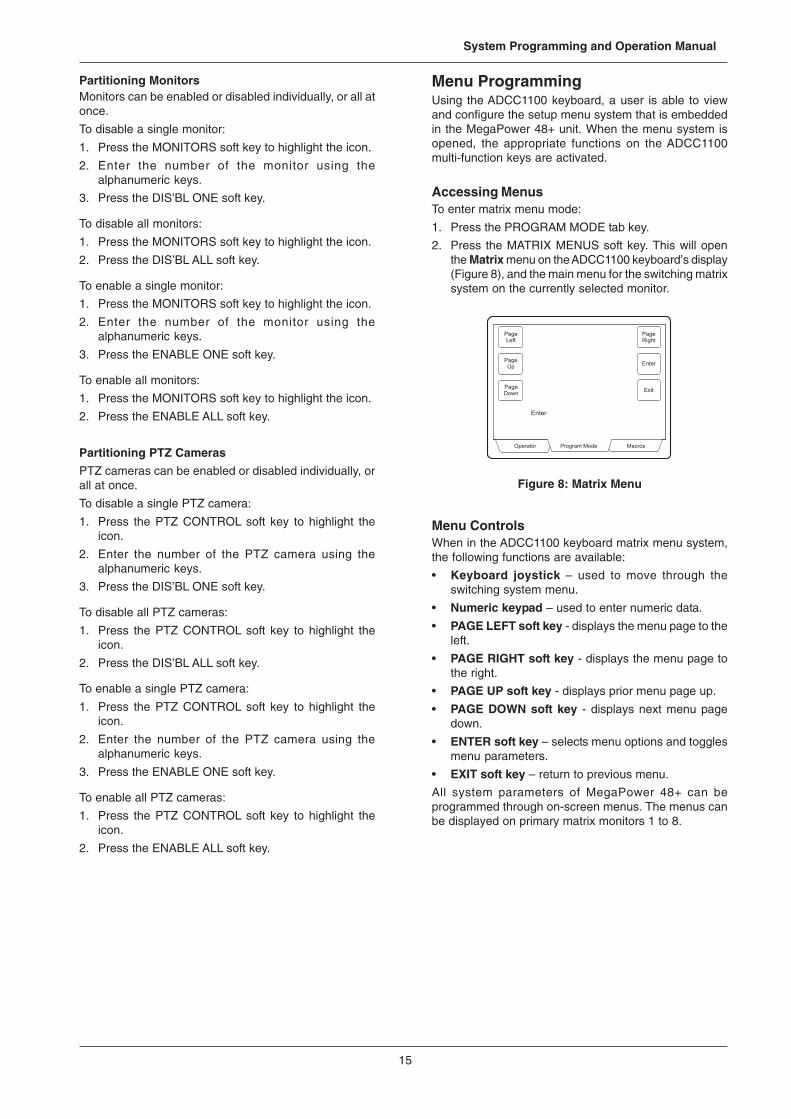
2. Press the MATRIX MENUS soft key. This will openthe Matrix menu on the ADCC1100 keyboard’s display(Figure 8), and the main menu for the switching matrixsystem on the currently selected monitor.
Figure 8: Matrix Menu
Menu ControlsWhen in the ADCC1100 keyboard matrix menu system,the following functions are available:
• Keyboard joystick – used to move through theswitching system menu.
• Numeric keypad – used to enter numeric data.
• PAGE LEFT soft key - displays the menu page to theleft.
• PAGE RIGHT soft key - displays the menu page tothe right.
• PAGE UP soft key - displays prior menu page up.
• PAGE DOWN soft key - displays next menu pagedown.
• ENTER soft key – selects menu options and togglesmenu parameters.
• EXIT soft key – return to previous menu.
All system parameters of MegaPower 48+ can beprogrammed through on-screen menus. The menus canbe displayed on primary matrix monitors 1 to 8.
16
MegaPowerTM 48+
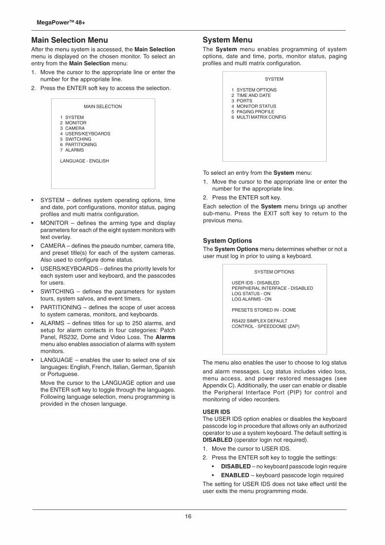
Main Selection MenuAfter the menu system is accessed, the Main Selectionmenu is displayed on the chosen monitor. To select anentry from the Main Selection menu:
1. Move the cursor to the appropriate line or enter thenumber for the appropriate line.
2. Press the ENTER soft key to access the selection.
MAIN SELECTION
1 SYSTEM2 MONITOR3 CAMERA4 USERS/KEYBOARDS5 SWITCHING6 PARTITIONING7 ALARMS
LANGUAGE - ENGLISH
System MenuThe System menu enables programming of systemoptions, date and time, ports, monitor status, pagingprofiles and multi matrix configuration.
SYSTEM
1 SYSTEM OPTIONS2 TIME AND DATE3 PORTS4 MONITOR STATUS5 PAGING PROFILE6 MULTI MATRIX CONFIG
• SYSTEM – defines system operating options, timeand date, port configurations, monitor status, pagingprofiles and multi matrix configuration.
• MONITOR – defines the arming type and displayparameters for each of the eight system monitors withtext overlay.
• CAMERA – defines the pseudo number, camera title,and preset title(s) for each of the system cameras.Also used to configure dome status.
• USERS/KEYBOARDS – defines the priority levels foreach system user and keyboard, and the passcodesfor users.
• SWITCHING – defines the parameters for systemtours, system salvos, and event timers.
• PARTITIONING – defines the scope of user accessto system cameras, monitors, and keyboards.
• ALARMS – defines titles for up to 250 alarms, andsetup for alarm contacts in four categories: PatchPanel, RS232, Dome and Video Loss. The Alarmsmenu also enables association of alarms with systemmonitors.
• LANGUAGE – enables the user to select one of sixlanguages: English, French, Italian, German, Spanishor Portuguese.
Move the cursor to the LANGUAGE option and usethe ENTER soft key to toggle through the languages.Following language selection, menu programming isprovided in the chosen language.
To select an entry from the System menu:
1. Move the cursor to the appropriate line or enter thenumber for the appropriate line.
2. Press the ENTER soft key.
Each selection of the System menu brings up anothersub-menu. Press the EXIT soft key to return to theprevious menu.
System OptionsThe System Options menu determines whether or not auser must log in prior to using a keyboard.
SYSTEM OPTIONS
USER IDS - DISABLEDPERIPHERAL INTERFACE - DISABLEDLOG STATUS - ONLOG ALARMS - ON
PRESETS STORED IN - DOME
RS422 SIMPLEX DEFAULTCONTROL - SPEEDDOME (ZAP)
The menu also enables the user to choose to log status
and alarm messages. Log status includes video loss,menu access, and power restored messages (seeAppendix C). Additionally, the user can enable or disablethe Peripheral Interface Port (PIP) for control andmonitoring of video recorders.
USER IDSThe USER IDS option enables or disables the keyboardpasscode log in procedure that allows only an authorizedoperator to use a system keyboard. The default setting isDISABLED (operator login not required).
1. Move the cursor to USER IDS.
2. Press the ENTER soft key to toggle the settings:
• DISABLED – no keyboard passcode login require
• ENABLED – keyboard passcode login required
The setting for USER IDS does not take effect until theuser exits the menu programming mode.

17
System Programming and Operation Manual
PERIPHERAL INTERFACETo enable or disable the Peripheral Interface Port (PIP):
1. Move the cursor to PERIPHERAL INTERFACE.
2. Press the ENTER soft key to step through the availableports and the DISABLED option.
Note: if the Peripheral Interface Port is enabled, PIPparameters must be programmed in the Ports menu.
LOG STATUS1. Move the cursor to LOG STATUS.
2. Press the ENTER soft key to toggle ON and OFF.
LOG ALARMS1. Move the cursor to LOG ALARMS.
2. Press the ENTER soft key to toggle ON and OFF.
PRESETS STORED IN / RS422 SIMPLEX CONTROLUsually, presets are stored in the matrix, and thePRESETS STORED IN line will be set to MATRIX.However, in applications where return data from domesis not available on RS422, it is not possible to store presetsin the matrix, and the PRESETS STORED IN line mustbe set to DOME. Presets are stored in the individualdomes and the matrix will work with simplex data to alldomes.
When presets are stored in the domes, the RS422SIMPLEX CONTROL line is used to specify the type ofdomes that have been connected. If the connected domesare legacy minidomes with only a single speed, selectthe MINIDOME (FIX SPEED) option. Otherwise, set thisoption to SPEEDDOME (ZAP).
To complete these fields, follow the steps below:
1. Move the cursor to PRESETS STORED IN.
2. If required, press the ENTER soft key to toggle thesetting from MATRIX and DOME.
3. When DOME is selected, the RS422 SIMPLEXCONTROL line is enabled. Press the ENTER soft keyagain to toggle between SPEEDDOME (ZAP) andMINIDOME (FIX SPEED).
Pressing the ENTER soft key again will disable thissecond field and return the PRESETS STORED INsetting to MATRIX.
Note: By default, presets are stored in the matrix whendomes are connected by SensorNet or RS422. However,when domes are configured for Manchester dataconnections, presets are stored in the dome. Therefore,if domes configured by Manchester data connections areincluded in the system, this option must be set to DOME.
Press the EXIT soft key to return to the previous menu.
TIME AND DATE
YEAR FORMAT - YYDATE FORMAT - MM - DD – YYMONTH - 01DAY - 05YEAR - 2003TIME - 16 : 32 : 45
Time and DateThe Time and Date menu enables the setting of the yearformat, date format, date, and time.
YEAR FORMAT determines whether the entered year willappear in two digit or four digit format. Note that the dateformat and date fields will reflect the year format choice.
1. Move the cursor to the YEAR FORMAT field.
2. Press the ENTER soft key to toggle between the twoyear formats (two digit and four digit).
DATE FORMAT selects the system date format. Note thatthe year format selection discussed above will beautomatically reflected in the date format.
1. Move the cursor to the DATE FORMAT field.
2. Press the ENTER soft key to step through the threeformat choices: MM-DD-YY (or YYYY), DD-MM-YY(or YYYY), and YY (or YYYY)-MM-DD.
MONTH displays the current month in two-digit format.
1. Move the cursor to the MONTH field.
2. Enter two digits for the month, and press the ENTERsoft key to accept the selection.
DAY displays the current day in two-digit format.
1. Move the cursor to the DAY field.
2. Enter two digits for the day, and press the ENTERsoft key to accept the selection.
YEAR displays the current system year in four-digit format.
1. Move the cursor to the YEAR field.
2. Enter the last two digits for the year and press theENTER soft key to accept the selection.
TIME enters hours, minutes and seconds in 24 hour format.
1. Move the cursor to the TIME field.2. Enter the hour in two digits and press the ENTER soft
key.3. Enter the minutes in two digits and press the ENTER
soft key.4. Enter the seconds in two digits and press the ENTER
soft key.Press the EXIT soft key to return to the previous menu.
18
MegaPowerTM 48+
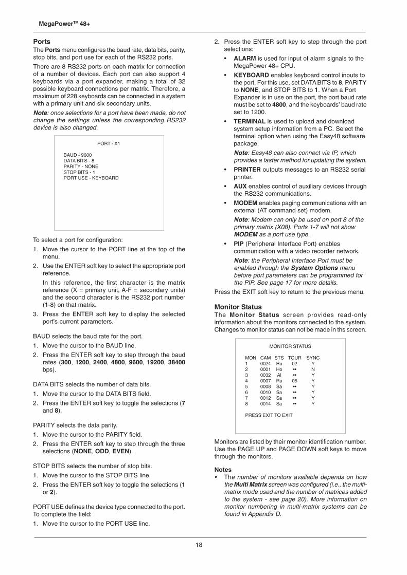
PortsThe Ports menu configures the baud rate, data bits, parity,stop bits, and port use for each of the RS232 ports.
There are 8 RS232 ports on each matrix for connectionof a number of devices. Each port can also support 4keyboards via a port expander, making a total of 32possible keyboard connections per matrix. Therefore, amaximum of 228 keyboards can be connected in a systemwith a primary unit and six secondary units.
Note: once selections for a port have been made, do notchange the settings unless the corresponding RS232device is also changed.
MONITOR STATUS
MON CAM STS TOUR SYNC1 0024 Ru 02 Y2 0001 Ho •• N3 0032 Al •• Y4 0007 Ru 05 Y5 0008 Sa •• Y6 0010 Sa •• Y7 0012 Sa •• Y8 0014 Sa •• Y
PRESS EXIT TO EXIT
2. Press the ENTER soft key to step through the portselections:
• ALARM is used for input of alarm signals to theMegaPower 48+ CPU.
• KEYBOARD enables keyboard control inputs tothe port. For this use, set DATA BITS to 8, PARITYto NONE, and STOP BITS to 1. When a PortExpander is in use on the port, the port baud ratemust be set to 4800, and the keyboards’ baud rateset to 1200.
• TERMINAL is used to upload and downloadsystem setup information from a PC. Select theterminal option when using the Easy48 softwarepackage.
Note: Easy48 can also connect via IP, whichprovides a faster method for updating the system.
• PRINTER outputs messages to an RS232 serialprinter.
• AUX enables control of auxiliary devices throughthe RS232 communications.
• MODEM enables paging communications with anexternal (AT command set) modem.
Note: Modem can only be used on port 8 of theprimary matrix (X08). Ports 1-7 will not showMODEM as a port use type.
• PIP (Peripheral Interface Port) enablescommunication with a video recorder network.
Note: the Peripheral Interface Port must beenabled through the System Options menubefore port parameters can be programmed forthe PIP. See page 17 for more details.
Press the EXIT soft key to return to the previous menu.
Monitor StatusThe Monitor Status screen provides read-onlyinformation about the monitors connected to the system.Changes to monitor status can not be made in ths screen.
PORT - X1
BAUD - 9600DATA BITS - 8PARITY - NONESTOP BITS - 1PORT USE - KEYBOARD
To select a port for configuration:
1. Move the cursor to the PORT line at the top of themenu.
2. Use the ENTER soft key to select the appropriate portreference.
In this reference, the first character is the matrixreference (X = primary unit, A-F = secondary units)and the second character is the RS232 port number(1-8) on that matrix.
3. Press the ENTER soft key to display the selectedport’s current parameters.
BAUD selects the baud rate for the port.
1. Move the cursor to the BAUD line.
2. Press the ENTER soft key to step through the baudrates (300, 1200, 2400, 4800, 9600, 19200, 38400bps).
DATA BITS selects the number of data bits.
1. Move the cursor to the DATA BITS field.
2. Press the ENTER soft key to toggle the selections (7and 8).
PARITY selects the data parity.
1. Move the cursor to the PARITY field.
2. Press the ENTER soft key to step through the threeselections (NONE, ODD, EVEN).
STOP BITS selects the number of stop bits.
1. Move the cursor to the STOP BITS line.
2. Press the ENTER soft key to toggle the selections (1or 2).
PORT USE defines the device type connected to the port.To complete the field:
1. Move the cursor to the PORT USE line.
Monitors are listed by their monitor identification number.Use the PAGE UP and PAGE DOWN soft keys to movethrough the monitors.
Notes• The number of monitors available depends on how
the Multi Matrix screen was configured (i.e., the multi-matrix mode used and the number of matrices addedto the system - see page 20). More information onmonitor numbering in multi-matrix systems can befound in Appendix D.
19
System Programming and Operation Manual
• Video output X16 (primary matrix, output port 16) isused by the system to sample video. If video lossdetection is enabled for any system video input, videooutput X16 will not be available for video switching.
Monitor information provided includes the following:
• CAM – camera number currently displayed on themonitor.
• STS – monitor status display codes include Ho = Hold,Ru = Run, Al = Alarm, Sa = Salvo
• TOUR – tour currently running on the monitor.
• SYNC – camera sync display codes indicate thepresence or absence of video sync (“S”) signals:
• Y = sync (video) present
• N = loss of sync (video)
The Monitor Status screen shown provides the followinginformation:
• Monitor 1 is currently displaying camera 0024, withtour 2 in run mode. The sync signal is present.
• Monitor 2 is currently held on camera 0001, but thereis a loss of sync on the camera.
Press the EXIT soft key to return to the previous menu.
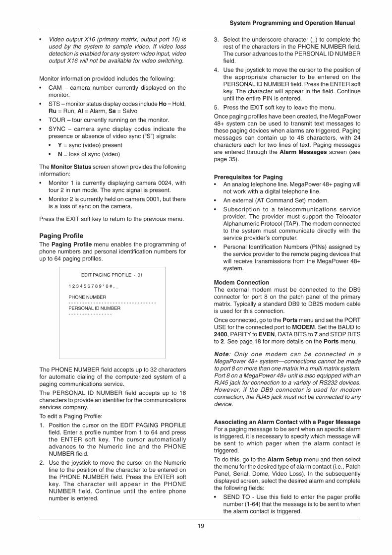
Paging ProfileThe Paging Profile menu enables the programming ofphone numbers and personal identification numbers forup to 64 paging profiles.
EDIT PAGING PROFILE - 01
1 2 3 4 5 6 7 8 9 * 0 # , _
PHONE NUMBER- - - - - - - - - - - - - - - - - - - - - - - - - - - - - - - -PERSONAL ID NUMBER- - - - - - - - - - - - - - - -
3. Select the underscore character (_) to complete therest of the characters in the PHONE NUMBER field.The cursor advances to the PERSONAL ID NUMBERfield.
4. Use the joystick to move the cursor to the position ofthe appropriate character to be entered on thePERSONAL ID NUMBER field. Press the ENTER softkey. The character will appear in the field. Continueuntil the entire PIN is entered.
5. Press the EXIT soft key to leave the menu.
Once paging profiles have been created, the MegaPower48+ system can be used to transmit text messages tothese paging devices when alarms are triggered. Pagingmessages can contain up to 48 characters, with 24characters each for two lines of text. Paging messagesare entered through the Alarm Messages screen (seepage 35).
Prerequisites for Paging• An analog telephone line. MegaPower 48+ paging will
not work with a digital telephone line.
• An external (AT Command Set) modem.
• Subscription to a telecommunications serviceprovider. The provider must support the TelocatorAlphanumeric Protocol (TAP). The modem connectedto the system must communicate directly with theservice provider’s computer.
• Personal Identification Numbers (PINs) assigned bythe service provider to the remote paging devices thatwill receive transmissions from the MegaPower 48+system.
Modem ConnectionThe external modem must be connected to the DB9connector for port 8 on the patch panel of the primarymatrix. Typically a standard DB9 to DB25 modem cableis used for this connection.
Once connected, go to the Ports menu and set the PORTUSE for the connected port to MODEM. Set the BAUD to2400, PARITY to EVEN, DATA BITS to 7 and STOP BITSto 2. See page 18 for more details on the Ports menu.
Note: Only one modem can be connected in aMegaPower 48+ system—connections cannot be madeto port 8 on more than one matrix in a multi matrix system.Port 8 on a MegaPower 48+ unit is also equipped with anRJ45 jack for connection to a variety of RS232 devices.However, if the DB9 connector is used for modemconnection, the RJ45 jack must not be connected to anydevice.
Associating an Alarm Contact with a Pager MessageFor a paging message to be sent when an specific alarmis triggered, it is necessary to specify which message willbe sent to which pager when the alarm contact istriggered.
To do this, go to the Alarm Setup menu and then selectthe menu for the desired type of alarm contact (i.e., PatchPanel, Serial, Dome, Video Loss). In the subsequentlydisplayed screen, select the desired alarm and completethe following fields:
• SEND TO - Use this field to enter the pager profilenumber (1-64) that the message is to be sent to whenthe alarm contact is triggered.
The PHONE NUMBER field accepts up to 32 charactersfor automatic dialing of the computerized system of apaging communications service.
The PERSONAL ID NUMBER field accepts up to 16characters to provide an identifier for the communicationsservices company.
To edit a Paging Profile:
1. Position the cursor on the EDIT PAGING PROFILEfield. Enter a profile number from 1 to 64 and pressthe ENTER soft key. The cursor automaticallyadvances to the Numeric line and the PHONENUMBER field.
2. Use the joystick to move the cursor on the Numericline to the position of the character to be entered onthe PHONE NUMBER field. Press the ENTER softkey. The character will appear in the PHONENUMBER field. Continue until the entire phonenumber is entered.
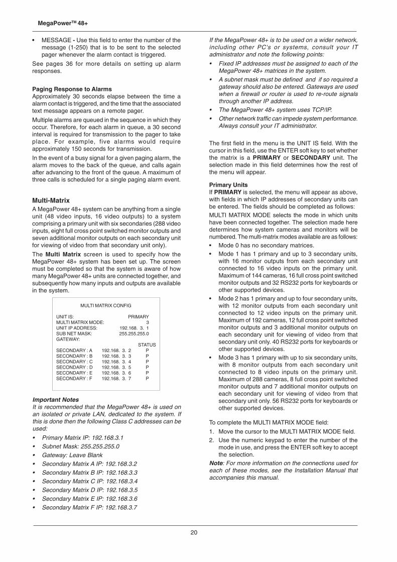
20
MegaPowerTM 48+
• MESSAGE - Use this field to enter the number of themessage (1-250) that is to be sent to the selectedpager whenever the alarm contact is triggered.
See pages 36 for more details on setting up alarmresponses.
Paging Response to AlarmsApproximately 30 seconds elapse between the time aalarm contact is triggered, and the time that the associatedtext message appears on a remote pager.
Multiple alarms are queued in the sequence in which theyoccur. Therefore, for each alarm in queue, a 30 secondinterval is required for transmission to the pager to takeplace. For example, five alarms would requireapproximately 150 seconds for transmission.
In the event of a busy signal for a given paging alarm, thealarm moves to the back of the queue, and calls againafter advancing to the front of the queue. A maximum ofthree calls is scheduled for a single paging alarm event.
Multi-MatrixA MegaPower 48+ system can be anything from a singleunit (48 video inputs, 16 video outputs) to a systemcomprising a primary unit with six secondaries (288 videoinputs, eight full cross point switched monitor outputs andseven additional monitor outputs on each secondary unitfor viewing of video from that secondary unit only).
The Multi Matrix screen is used to specify how theMegaPower 48+ system has been set up. The screenmust be completed so that the system is aware of howmany MegaPower 48+ units are connected together, andsubsequently how many inputs and outputs are availablein the system.
MULTI MATRIX CONFIG
UNIT IS: PRIMARYMULTI MATRIX MODE: 3UNIT IP ADDRESS: 192.168. 3. 1SUB NET MASK: 255.255.255.0GATEWAY:
STATUSSECONDARY : A 192.168. 3. 2 PSECONDARY : B 192.168. 3. 3 PSECONDARY : C 192.168. 3. 4 PSECONDARY : D 192.168. 3. 5 PSECONDARY : E 192.168. 3. 6 PSECONDARY : F 192.168. 3. 7 P
If the MegaPower 48+ is to be used on a wider network,including other PC's or systems, consult your ITadministrator and note the following points:
• Fixed IP addresses must be assigned to each of theMegaPower 48+ matrices in the system.
• A subnet mask must be defined and if so required agateway should also be entered. Gateways are usedwhen a firewall or router is used to re-route signalsthrough another IP address.
• The MegaPower 48+ system uses TCP/IP.• Other network traffic can impede system performance.
Always consult your IT administrator.
The first field in the menu is the UNIT IS field. With thecursor in this field, use the ENTER soft key to set whetherthe matrix is a PRIMARY or SECONDARY unit. Theselection made in this field determines how the rest ofthe menu will appear.
Primary UnitsIf PRIMARY is selected, the menu will appear as above,with fields in which IP addresses of secondary units canbe entered. The fields should be completed as follows:MULTI MATRIX MODE selects the mode in which unitshave been connected together. The selection made heredetermines how system cameras and monitors will benumbered. The multi-matrix modes available are as follows:• Mode 0 has no secondary matrices.• Mode 1 has 1 primary and up to 3 secondary units,
with 16 monitor outputs from each secondary unitconnected to 16 video inputs on the primary unit.Maximum of 144 cameras, 16 full cross point switchedmonitor outputs and 32 RS232 ports for keyboards orother supported devices.
• Mode 2 has 1 primary and up to four secondary units,with 12 monitor outputs from each secondary unitconnected to 12 video inputs on the primary unit.Maximum of 192 cameras, 12 full cross point switchedmonitor outputs and 3 additional monitor outputs oneach secondary unit for viewing of video from thatsecondary unit only. 40 RS232 ports for keyboards orother supported devices.
• Mode 3 has 1 primary with up to six secondary units,with 8 monitor outputs from each secondary unitconnected to 8 video inputs on the primary unit.Maximum of 288 cameras, 8 full cross point switchedmonitor outputs and 7 additional monitor outputs oneach secondary unit for viewing of video from thatsecondary unit only. 56 RS232 ports for keyboards orother supported devices.
To complete the MULTI MATRIX MODE field:
1. Move the cursor to the MULTI MATRIX MODE field.2. Use the numeric keypad to enter the number of the
mode in use, and press the ENTER soft key to acceptthe selection.
Note: For more information on the connections used foreach of these modes, see the Installation Manual thataccompanies this manual.
Important NotesIt is recommended that the MegaPower 48+ is used onan isolated or private LAN, dedicated to the system. Ifthis is done then the following Class C addresses can beused:
• Primary Matrix IP: 192.168.3.1• Subnet Mask: 255.255.255.0• Gateway: Leave Blank• Secondary Matrix A IP: 192.168.3.2• Secondary Matrix B IP: 192.168.3.3• Secondary Matrix C IP: 192.168.3.4• Secondary Matrix D IP: 192.168.3.5• Secondary Matrix E IP: 192.168.3.6• Secondary Matrix F IP: 192.168.3.7
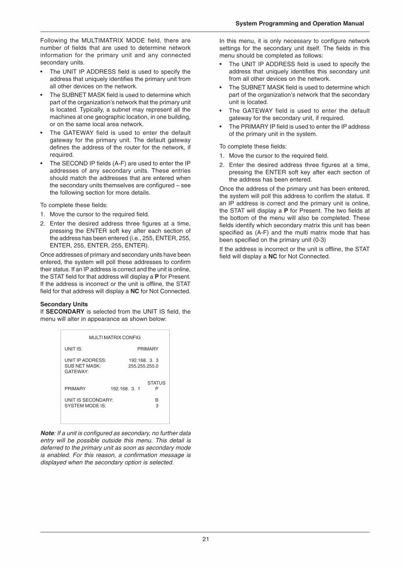
21
System Programming and Operation Manual
MULTI MATRIX CONFIG
UNIT IS: PRIMARY
UNIT IP ADDRESS: 192.168. 3. 3SUB NET MASK: 255.255.255.0GATEWAY:
STATUSPRIMARY 192.168. 3. 1 P
UNIT IS SECONDARY: BSYSTEM MODE IS: 3
Following the MULTIMATRIX MODE field, there arenumber of fields that are used to determine networkinformation for the primary unit and any connectedsecondary units.
• The UNIT IP ADDRESS field is used to specify theaddress that uniquely identifies the primary unit fromall other devices on the network.
• The SUBNET MASK field is used to determine whichpart of the organization’s network that the primary unitis located. Typically, a subnet may represent all themachines at one geographic location, in one building,or on the same local area network.
• The GATEWAY field is used to enter the defaultgateway for the primary unit. The default gatewaydefines the address of the router for the network, ifrequired.
• The SECOND IP fields (A-F) are used to enter the IPaddresses of any secondary units. These entriesshould match the addresses that are entered whenthe secondary units themselves are configured – seethe following section for more details.
To complete these fields:
1. Move the cursor to the required field.
2. Enter the desired address three figures at a time,pressing the ENTER soft key after each section ofthe address has been entered (i.e., 255, ENTER, 255,ENTER, 255, ENTER, 255, ENTER).
Once addresses of primary and secondary units have beenentered, the system will poll these addresses to confirmtheir status. If an IP address is correct and the unit is online,the STAT field for that address will display a P for Present.If the address is incorrect or the unit is offline, the STATfield for that address will display a NC for Not Connected.
Secondary UnitsIf SECONDARY is selected from the UNIT IS field, themenu will alter in appearance as shown below:
Note: If a unit is configured as secondary, no further dataentry will be possible outside this menu. This detail isdeferred to the primary unit as soon as secondary modeis enabled. For this reason, a confirmation message isdisplayed when the secondary option is selected.
In this menu, it is only necessary to configure networksettings for the secondary unit itself. The fields in thismenu should be completed as follows:• The UNIT IP ADDRESS field is used to specify the
address that uniquely identifies this secondary unitfrom all other devices on the network.
• The SUBNET MASK field is used to determine whichpart of the organization’s network that the secondaryunit is located.
• The GATEWAY field is used to enter the defaultgateway for the secondary unit, if required.
• The PRIMARY IP field is used to enter the IP addressof the primary unit in the system.
To complete these fields:
1. Move the cursor to the required field.
2. Enter the desired address three figures at a time,pressing the ENTER soft key after each section ofthe address has been entered.
Once the address of the primary unit has been entered,the system will poll this address to confirm the status. Ifan IP address is correct and the primary unit is online,the STAT will display a P for Present. The two fields atthe bottom of the menu will also be completed. Thesefields identify which secondary matrix this unit has beenspecified as (A-F) and the multi matrix mode that hasbeen specified on the primary unit (0-3)
If the address is incorrect or the unit is offline, the STATfield will display a NC for Not Connected.
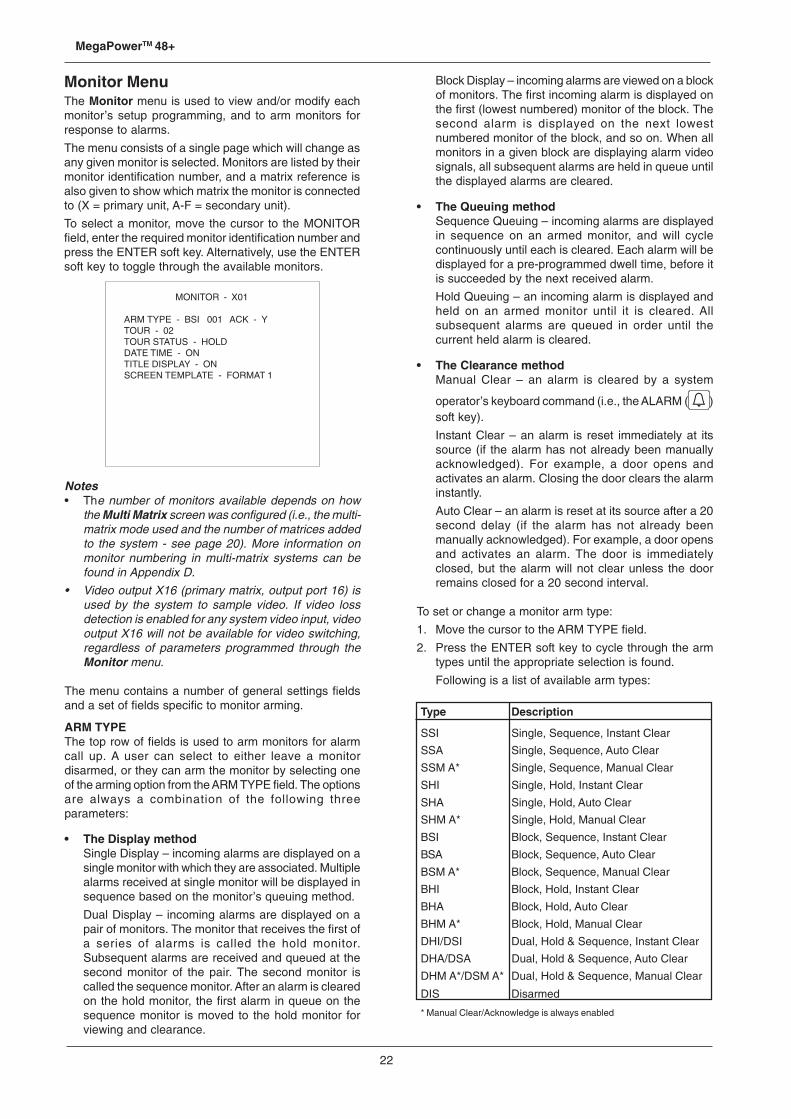
22
MegaPowerTM 48+
Monitor MenuThe Monitor menu is used to view and/or modify eachmonitor’s setup programming, and to arm monitors forresponse to alarms.
The menu consists of a single page which will change asany given monitor is selected. Monitors are listed by theirmonitor identification number, and a matrix reference isalso given to show which matrix the monitor is connectedto (X = primary unit, A-F = secondary unit).
To select a monitor, move the cursor to the MONITORfield, enter the required monitor identification number andpress the ENTER soft key. Alternatively, use the ENTERsoft key to toggle through the available monitors.
Block Display – incoming alarms are viewed on a blockof monitors. The first incoming alarm is displayed onthe first (lowest numbered) monitor of the block. Thesecond alarm is displayed on the next lowestnumbered monitor of the block, and so on. When allmonitors in a given block are displaying alarm videosignals, all subsequent alarms are held in queue untilthe displayed alarms are cleared.
• The Queuing methodSequence Queuing – incoming alarms are displayedin sequence on an armed monitor, and will cyclecontinuously until each is cleared. Each alarm will bedisplayed for a pre-programmed dwell time, before itis succeeded by the next received alarm.
Hold Queuing – an incoming alarm is displayed andheld on an armed monitor until it is cleared. Allsubsequent alarms are queued in order until thecurrent held alarm is cleared.
• The Clearance methodManual Clear – an alarm is cleared by a system
operator’s keyboard command (i.e., the ALARM ( )soft key).
Instant Clear – an alarm is reset immediately at itssource (if the alarm has not already been manuallyacknowledged). For example, a door opens andactivates an alarm. Closing the door clears the alarminstantly.
Auto Clear – an alarm is reset at its source after a 20second delay (if the alarm has not already beenmanually acknowledged). For example, a door opensand activates an alarm. The door is immediatelyclosed, but the alarm will not clear unless the doorremains closed for a 20 second interval.
To set or change a monitor arm type:
1. Move the cursor to the ARM TYPE field.
2. Press the ENTER soft key to cycle through the armtypes until the appropriate selection is found.
Following is a list of available arm types:
MONITOR - X01
ARM TYPE - BSI 001 ACK - YTOUR - 02TOUR STATUS - HOLDDATE TIME - ONTITLE DISPLAY - ONSCREEN TEMPLATE - FORMAT 1
Notes• The number of monitors available depends on how
the Multi Matrix screen was configured (i.e., the multi-matrix mode used and the number of matrices addedto the system - see page 20). More information onmonitor numbering in multi-matrix systems can befound in Appendix D.
• Video output X16 (primary matrix, output port 16) isused by the system to sample video. If video lossdetection is enabled for any system video input, videooutput X16 will not be available for video switching,regardless of parameters programmed through theMonitor menu.
The menu contains a number of general settings fieldsand a set of fields specific to monitor arming.
ARM TYPEThe top row of fields is used to arm monitors for alarmcall up. A user can select to either leave a monitordisarmed, or they can arm the monitor by selecting oneof the arming option from the ARM TYPE field. The optionsare always a combination of the following threeparameters:
• The Display methodSingle Display – incoming alarms are displayed on asingle monitor with which they are associated. Multiplealarms received at single monitor will be displayed insequence based on the monitor’s queuing method.
Dual Display – incoming alarms are displayed on apair of monitors. The monitor that receives the first ofa series of alarms is called the hold monitor.Subsequent alarms are received and queued at thesecond monitor of the pair. The second monitor iscalled the sequence monitor. After an alarm is clearedon the hold monitor, the first alarm in queue on thesequence monitor is moved to the hold monitor forviewing and clearance.
Type Description
SSI Single, Sequence, Instant Clear
SSA Single, Sequence, Auto Clear
SSM A* Single, Sequence, Manual Clear
SHI Single, Hold, Instant Clear
SHA Single, Hold, Auto Clear
SHM A* Single, Hold, Manual Clear
BSI Block, Sequence, Instant Clear
BSA Block, Sequence, Auto Clear
BSM A* Block, Sequence, Manual Clear
BHI Block, Hold, Instant Clear
BHA Block, Hold, Auto Clear
BHM A* Block, Hold, Manual Clear
DHI/DSI Dual, Hold & Sequence, Instant Clear
DHA/DSA Dual, Hold & Sequence, Auto Clear
DHM A*/DSM A* Dual, Hold & Sequence, Manual Clear
DIS Disarmed
* Manual Clear/Acknowledge is always enabled
23
System Programming and Operation Manual
BLOCKWhen an arming option with a block display method hasbeen selected, the BLOCK field is activated (the threenumbers shown after the monitor arming code). This fieldis used to add the monitor to a block. A monitor block canconsist of any set of connected monitors—the monitorsdo not need to be contiguous.
For example, if an alarm is set to call a salvo when it istriggered, the salvo will be displayed on all monitors thathave been allocated this block number.
To select or change a block number for a monitor:
1. Move the cursor to the BLOCK field.
2. Enter the appropriate block number (1-16).
3. Press the ENTER soft key.
Notes• The alarm clearance method for the block is set by
the arming code of the lowest number monitor of theblock only.
• The queuing method can be set differently for eachmonitor in the block. Queuing restrictions only applyif the monitor block is to display system or link salvos.To arm a monitor block salvo for hold queuing, allmonitors in the block must be set to a hold queuingmethod. To arm a monitor block salvo for sequencequeuing, arm the lowest number monitor of the blockto a sequence queuing method and arm the remainingmonitors to a hold queuing method.
• Associate alarm contacts with the first monitor of theblock only. Do not associate any alarm contacts tothe remaining monitors in the block. See page 38 formore details on creating alarm associations.
ACK (Manual Acknowledge)The ACK field enables or disables the manual clearfeature for instant and auto clear arming codes. Thisfeature must be programmed after the monitor is armedwith an instant or auto clear alarm type.
To set up manual clear/acknowledge for Instant or Auto:
1. Move the cursor to the ACK field.
2. Press the ENTER soft key to toggle between Y andN.
• Y (ACK enabled) – when enabled, the letter “A” isdisplayed after the arm type (e.g. SSI A).
• N (ACK disabled) – when disabled, the letter “A”does not appear after the arm type.
Note: the ACK entry cannot be set to N if a manualclear arm type code is selected for the monitor.
TOURThe TOUR entry indicates the system tour (1-64) currentlyassociated with the monitor. An entry of “—” indicatesthat a scratch pad tour or no tour is associated with themonitor.
To change the tour currently running on the monitor:
1. Move the cursor to the TOUR field.
2. Enter the number (1-64) of the appropriate tour.
3. Press the ENTER soft key.
TOUR STATUSTOUR STATUS indicates whether the tour on the currentlyselected monitor is in run or hold condition.
To change the tour status:
1. Move the cursor to the TOUR STATUS field.
2. Press the ENTER soft key to toggle options.
DATE TIMEThe DATE TIME entry indicates if the date and time displayis on or off for this monitor’s on-screen display.
To change the time date display on this monitor:
1. Move the cursor to the DATE TIME field.
2. Press the ENTER soft key to toggle between ON andOFF.
TITLE DISPLAYThe TITLE DISPLAY entry indicates if the title display ison or off for this monitor’s on-screen display.
To change the title display on this monitor:
1. Move the cursor to the TITLE DISPLAY field.
2. Press the ENTER soft key to toggle between ON andOFF.
Note: On-screen text display is available on primarymatrix monitors 1-8 and also on any monitors connectedto secondary matrices.
SCREEN TEMPLATEThe SCREEN TEMPLATE field enables the choice of oneof two monitor display formats. Format 1 shows thecamera number, status line, camera title, and date & timedisplayed on the bottom of the screen. Format 2 showsequivalent information displayed on the top of the screen(see the section System Monitor On-Screen Displayson page 5).
To choose the appropriate screen template:
1. Move to the SCREEN TEMPLATE field.
2. Press the ENTER soft key to toggle between FORMAT1 and FORMAT 2.
Note: On-screen text display is available on primarymatrix monitors 1-8 and also on any monitors connectedto secondary matrices.
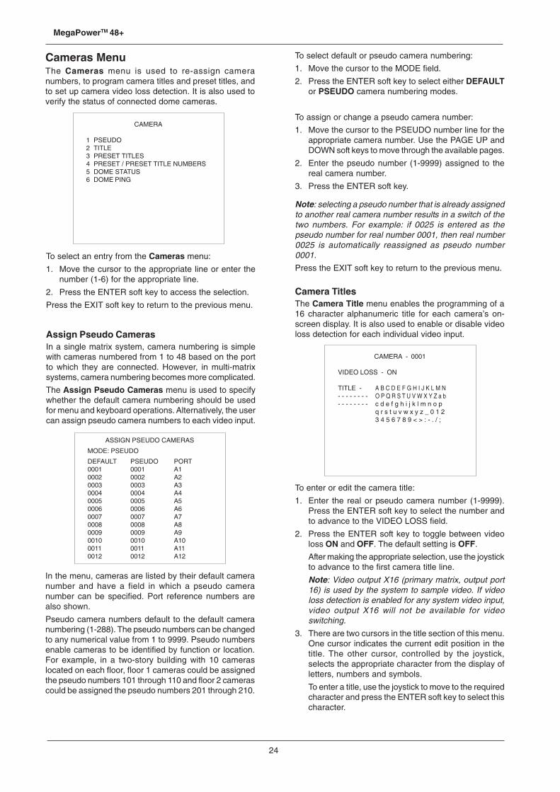
24
MegaPowerTM 48+
To select default or pseudo camera numbering:
1. Move the cursor to the MODE field.
2. Press the ENTER soft key to select either DEFAULTor PSEUDO camera numbering modes.
To assign or change a pseudo camera number:
1. Move the cursor to the PSEUDO number line for theappropriate camera number. Use the PAGE UP andDOWN soft keys to move through the available pages.
2. Enter the pseudo number (1-9999) assigned to thereal camera number.
3. Press the ENTER soft key.
Note: selecting a pseudo number that is already assignedto another real camera number results in a switch of thetwo numbers. For example: if 0025 is entered as thepseudo number for real number 0001, then real number0025 is automatically reassigned as pseudo number0001.
Press the EXIT soft key to return to the previous menu.
Camera TitlesThe Camera Title menu enables the programming of a16 character alphanumeric title for each camera’s on-screen display. It is also used to enable or disable videoloss detection for each individual video input.
To enter or edit the camera title:
1. Enter the real or pseudo camera number (1-9999).Press the ENTER soft key to select the number andto advance to the VIDEO LOSS field.
2. Press the ENTER soft key to toggle between videoloss ON and OFF. The default setting is OFF.
After making the appropriate selection, use the joystickto advance to the first camera title line.
Note: Video output X16 (primary matrix, output port16) is used by the system to sample video. If videoloss detection is enabled for any system video input,video output X16 will not be available for videoswitching.
3. There are two cursors in the title section of this menu.One cursor indicates the current edit position in thetitle. The other cursor, controlled by the joystick,selects the appropriate character from the display ofletters, numbers and symbols.
To enter a title, use the joystick to move to the requiredcharacter and press the ENTER soft key to select thischaracter.
Cameras MenuThe Cameras menu is used to re-assign cameranumbers, to program camera titles and preset titles, andto set up camera video loss detection. It is also used toverify the status of connected dome cameras.
CAMERA - 0001
VIDEO LOSS - ON
TITLE - A B C D E F G H I J K L M N- - - - - - - - O P Q R S T U V W X Y Z a b- - - - - - - - c d e f g h i j k l m n o p
q r s t u v w x y z _ 0 1 23 4 5 6 7 8 9 < > : - . / ;
To select an entry from the Cameras menu:
1. Move the cursor to the appropriate line or enter thenumber (1-6) for the appropriate line.
2. Press the ENTER soft key to access the selection.
Press the EXIT soft key to return to the previous menu.
Assign Pseudo CamerasIn a single matrix system, camera numbering is simplewith cameras numbered from 1 to 48 based on the portto which they are connected. However, in multi-matrixsystems, camera numbering becomes more complicated.
The Assign Pseudo Cameras menu is used to specifywhether the default camera numbering should be usedfor menu and keyboard operations. Alternatively, the usercan assign pseudo camera numbers to each video input.
In the menu, cameras are listed by their default cameranumber and have a field in which a pseudo cameranumber can be specified. Port reference numbers arealso shown.
Pseudo camera numbers default to the default cameranumbering (1-288). The pseudo numbers can be changedto any numerical value from 1 to 9999. Pseudo numbersenable cameras to be identified by function or location.For example, in a two-story building with 10 cameraslocated on each floor, floor 1 cameras could be assignedthe pseudo numbers 101 through 110 and floor 2 camerascould be assigned the pseudo numbers 201 through 210.
CAMERA
1 PSEUDO2 TITLE3 PRESET TITLES4 PRESET / PRESET TITLE NUMBERS5 DOME STATUS6 DOME PING
ASSIGN PSEUDO CAMERAS
MODE: PSEUDO
DEFAULT PSEUDO PORT0001 0001 A10002 0002 A20003 0003 A30004 0004 A40005 0005 A50006 0006 A60007 0007 A70008 0008 A80009 0009 A90010 0010 A100011 0011 A110012 0012 A12
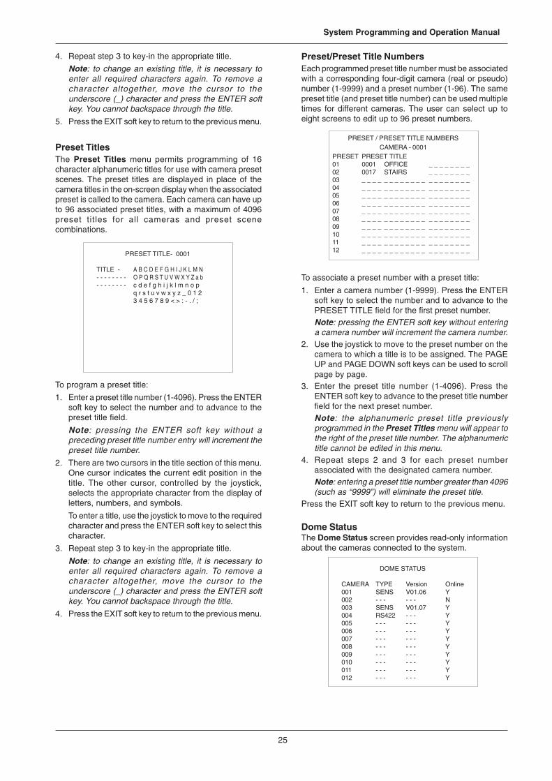
25
System Programming and Operation Manual
PRESET / PRESET TITLE NUMBERSCAMERA - 0001
PRESET PRESET TITLE01 0001 OFFICE _ _ _ _ _ _ _ _02 0017 STAIRS _ _ _ _ _ _ _ _03 _ _ _ _ _ _ _ _ _ _ _ _ _ _ _ _ _ _ _ _04 _ _ _ _ _ _ _ _ _ _ _ _ _ _ _ _ _ _ _ _05 _ _ _ _ _ _ _ _ _ _ _ _ _ _ _ _ _ _ _ _06 _ _ _ _ _ _ _ _ _ _ _ _ _ _ _ _ _ _ _ _07 _ _ _ _ _ _ _ _ _ _ _ _ _ _ _ _ _ _ _ _08 _ _ _ _ _ _ _ _ _ _ _ _ _ _ _ _ _ _ _ _09 _ _ _ _ _ _ _ _ _ _ _ _ _ _ _ _ _ _ _ _10 _ _ _ _ _ _ _ _ _ _ _ _ _ _ _ _ _ _ _ _11 _ _ _ _ _ _ _ _ _ _ _ _ _ _ _ _ _ _ _ _12 _ _ _ _ _ _ _ _ _ _ _ _ _ _ _ _ _ _ _ _
4. Repeat step 3 to key-in the appropriate title.
Note: to change an existing title, it is necessary toenter all required characters again. To remove acharacter altogether, move the cursor to theunderscore (_) character and press the ENTER softkey. You cannot backspace through the title.
5. Press the EXIT soft key to return to the previous menu.
Preset TitlesThe Preset Titles menu permits programming of 16character alphanumeric titles for use with camera presetscenes. The preset titles are displayed in place of thecamera titles in the on-screen display when the associatedpreset is called to the camera. Each camera can have upto 96 associated preset titles, with a maximum of 4096preset titles for all cameras and preset scenecombinations.
PRESET TITLE- 0001
TITLE - A B C D E F G H I J K L M N- - - - - - - - O P Q R S T U V W X Y Z a b- - - - - - - - c d e f g h i j k l m n o p
q r s t u v w x y z _ 0 1 23 4 5 6 7 8 9 < > : - . / ;
To program a preset title:
1. Enter a preset title number (1-4096). Press the ENTERsoft key to select the number and to advance to thepreset title field.
Note: pressing the ENTER soft key without apreceding preset title number entry will increment thepreset title number.
2. There are two cursors in the title section of this menu.One cursor indicates the current edit position in thetitle. The other cursor, controlled by the joystick,selects the appropriate character from the display ofletters, numbers, and symbols.
To enter a title, use the joystick to move to the requiredcharacter and press the ENTER soft key to select thischaracter.
3. Repeat step 3 to key-in the appropriate title.
Note: to change an existing title, it is necessary toenter all required characters again. To remove acharacter altogether, move the cursor to theunderscore (_) character and press the ENTER softkey. You cannot backspace through the title.
4. Press the EXIT soft key to return to the previous menu.
Preset/Preset Title NumbersEach programmed preset title number must be associatedwith a corresponding four-digit camera (real or pseudo)number (1-9999) and a preset number (1-96). The samepreset title (and preset title number) can be used multipletimes for different cameras. The user can select up toeight screens to edit up to 96 preset numbers.
To associate a preset number with a preset title:
1. Enter a camera number (1-9999). Press the ENTERsoft key to select the number and to advance to thePRESET TITLE field for the first preset number.Note: pressing the ENTER soft key without enteringa camera number will increment the camera number.
2. Use the joystick to move to the preset number on thecamera to which a title is to be assigned. The PAGEUP and PAGE DOWN soft keys can be used to scrollpage by page.
3. Enter the preset title number (1-4096). Press theENTER soft key to advance to the preset title numberfield for the next preset number.Note: the alphanumeric preset title previouslyprogrammed in the Preset Titles menu will appear tothe right of the preset title number. The alphanumerictitle cannot be edited in this menu.
4. Repeat steps 2 and 3 for each preset numberassociated with the designated camera number.Note: entering a preset title number greater than 4096(such as “9999”) will eliminate the preset title.
Press the EXIT soft key to return to the previous menu.
Dome StatusThe Dome Status screen provides read-only informationabout the cameras connected to the system.
DOME STATUS
CAMERA TYPE Version Online001 SENS V01.06 Y002 - - - - - - N003 SENS V01.07 Y004 RS422 - - - Y005 - - - - - - Y006 - - - - - - Y007 - - - - - - Y008 - - - - - - Y009 - - - - - - Y010 - - - - - - Y011 - - - - - - Y012 - - - - - - Y
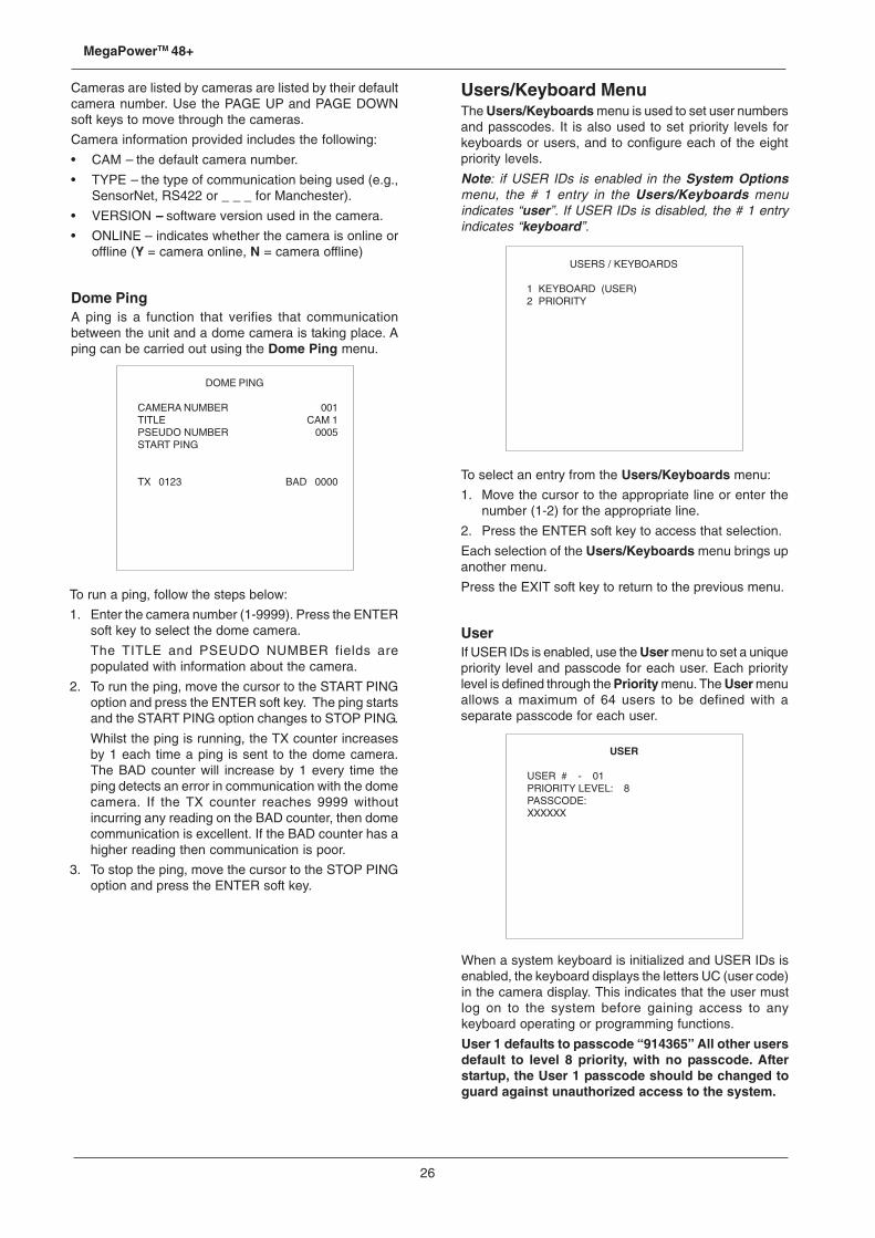
26
MegaPowerTM 48+
Cameras are listed by cameras are listed by their defaultcamera number. Use the PAGE UP and PAGE DOWNsoft keys to move through the cameras.
Camera information provided includes the following:
• CAM – the default camera number.
• TYPE – the type of communication being used (e.g.,SensorNet, RS422 or _ _ _ for Manchester).
• VERSION – software version used in the camera.
• ONLINE – indicates whether the camera is online oroffline (Y = camera online, N = camera offline)
Dome PingA ping is a function that verifies that communicationbetween the unit and a dome camera is taking place. Aping can be carried out using the Dome Ping menu.
USERS / KEYBOARDS
1 KEYBOARD (USER)2 PRIORITY
USER
USER # - 01PRIORITY LEVEL: 8PASSCODE:XXXXXX
To run a ping, follow the steps below:
1. Enter the camera number (1-9999). Press the ENTERsoft key to select the dome camera.
The TITLE and PSEUDO NUMBER fields arepopulated with information about the camera.
2. To run the ping, move the cursor to the START PINGoption and press the ENTER soft key. The ping startsand the START PING option changes to STOP PING.
Whilst the ping is running, the TX counter increasesby 1 each time a ping is sent to the dome camera.The BAD counter will increase by 1 every time theping detects an error in communication with the domecamera. If the TX counter reaches 9999 withoutincurring any reading on the BAD counter, then domecommunication is excellent. If the BAD counter has ahigher reading then communication is poor.
3. To stop the ping, move the cursor to the STOP PINGoption and press the ENTER soft key.
Users/Keyboard MenuThe Users/Keyboards menu is used to set user numbersand passcodes. It is also used to set priority levels forkeyboards or users, and to configure each of the eightpriority levels.
Note: if USER IDs is enabled in the System Optionsmenu, the # 1 entry in the Users/Keyboards menuindicates “user”. If USER IDs is disabled, the # 1 entryindicates “keyboard”.
To select an entry from the Users/Keyboards menu:
1. Move the cursor to the appropriate line or enter thenumber (1-2) for the appropriate line.
2. Press the ENTER soft key to access that selection.
Each selection of the Users/Keyboards menu brings upanother menu.
Press the EXIT soft key to return to the previous menu.
UserIf USER IDs is enabled, use the User menu to set a uniquepriority level and passcode for each user. Each prioritylevel is defined through the Priority menu. The User menuallows a maximum of 64 users to be defined with aseparate passcode for each user.
DOME PING
CAMERA NUMBER 001TITLE CAM 1PSEUDO NUMBER 0005START PING
TX 0123 BAD 0000
When a system keyboard is initialized and USER IDs isenabled, the keyboard displays the letters UC (user code)in the camera display. This indicates that the user mustlog on to the system before gaining access to anykeyboard operating or programming functions.
User 1 defaults to passcode “914365” All other usersdefault to level 8 priority, with no passcode. Afterstartup, the User 1 passcode should be changed toguard against unauthorized access to the system.
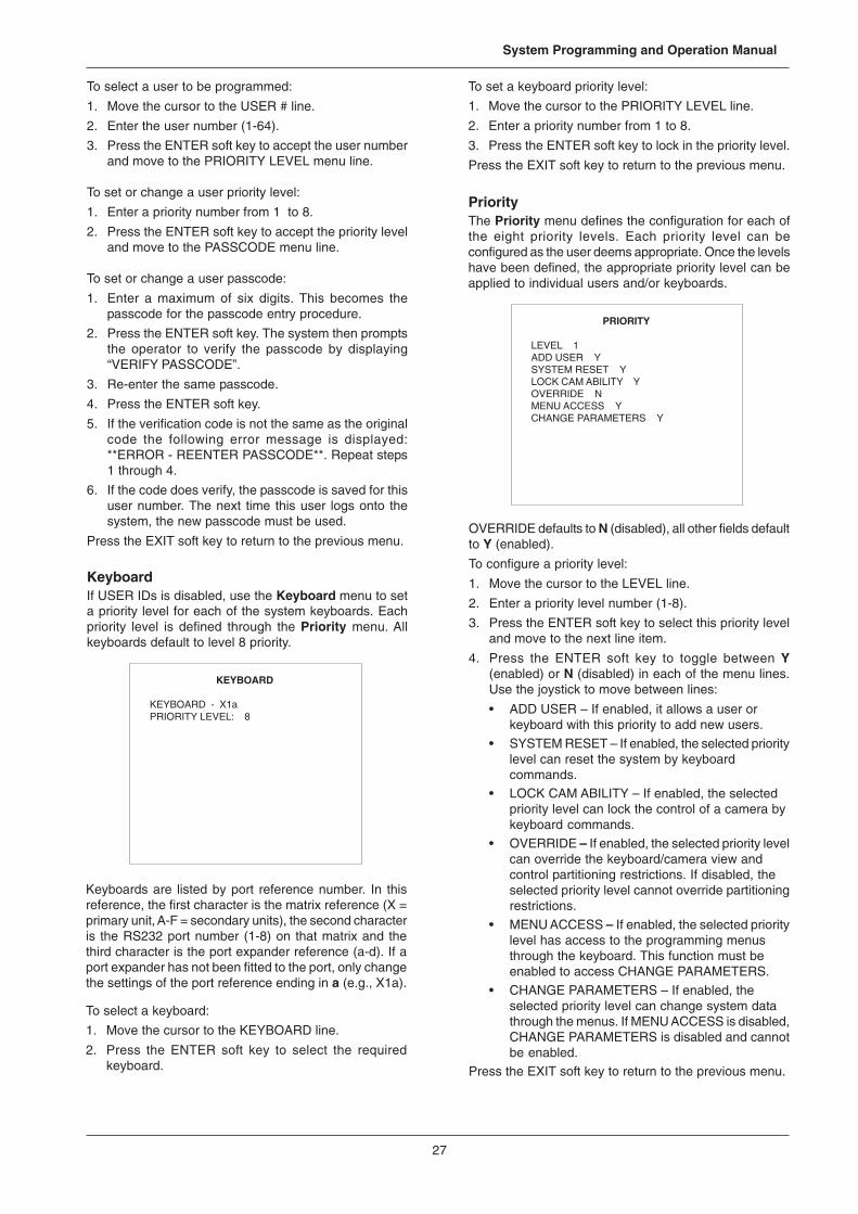
27
System Programming and Operation Manual
KEYBOARD
KEYBOARD - X1aPRIORITY LEVEL: 8
To select a user to be programmed:
1. Move the cursor to the USER # line.
2. Enter the user number (1-64).
3. Press the ENTER soft key to accept the user numberand move to the PRIORITY LEVEL menu line.
To set or change a user priority level:
1. Enter a priority number from 1 to 8.
2. Press the ENTER soft key to accept the priority leveland move to the PASSCODE menu line.
To set or change a user passcode:
1. Enter a maximum of six digits. This becomes thepasscode for the passcode entry procedure.
2. Press the ENTER soft key. The system then promptsthe operator to verify the passcode by displaying“VERIFY PASSCODE”.
3. Re-enter the same passcode.
4. Press the ENTER soft key.
5. If the verification code is not the same as the originalcode the following error message is displayed:**ERROR - REENTER PASSCODE**. Repeat steps1 through 4.
6. If the code does verify, the passcode is saved for thisuser number. The next time this user logs onto thesystem, the new passcode must be used.
Press the EXIT soft key to return to the previous menu.
KeyboardIf USER IDs is disabled, use the Keyboard menu to seta priority level for each of the system keyboards. Eachpriority level is defined through the Priority menu. Allkeyboards default to level 8 priority.
Keyboards are listed by port reference number. In thisreference, the first character is the matrix reference (X =primary unit, A-F = secondary units), the second characteris the RS232 port number (1-8) on that matrix and thethird character is the port expander reference (a-d). If aport expander has not been fitted to the port, only changethe settings of the port reference ending in a (e.g., X1a).
To select a keyboard:
1. Move the cursor to the KEYBOARD line.
2. Press the ENTER soft key to select the requiredkeyboard.
To set a keyboard priority level:
1. Move the cursor to the PRIORITY LEVEL line.
2. Enter a priority number from 1 to 8.
3. Press the ENTER soft key to lock in the priority level.
Press the EXIT soft key to return to the previous menu.
PriorityThe Priority menu defines the configuration for each ofthe eight priority levels. Each priority level can beconfigured as the user deems appropriate. Once the levelshave been defined, the appropriate priority level can beapplied to individual users and/or keyboards.
PRIORITY
LEVEL 1ADD USER YSYSTEM RESET YLOCK CAM ABILITY YOVERRIDE NMENU ACCESS YCHANGE PARAMETERS Y
OVERRIDE defaults to N (disabled), all other fields defaultto Y (enabled).
To configure a priority level:
1. Move the cursor to the LEVEL line.
2. Enter a priority level number (1-8).
3. Press the ENTER soft key to select this priority leveland move to the next line item.
4. Press the ENTER soft key to toggle between Y(enabled) or N (disabled) in each of the menu lines.Use the joystick to move between lines:
• ADD USER – If enabled, it allows a user orkeyboard with this priority to add new users.
• SYSTEM RESET – If enabled, the selected prioritylevel can reset the system by keyboardcommands.
• LOCK CAM ABILITY – If enabled, the selectedpriority level can lock the control of a camera bykeyboard commands.
• OVERRIDE – If enabled, the selected priority levelcan override the keyboard/camera view andcontrol partitioning restrictions. If disabled, theselected priority level cannot override partitioningrestrictions.
• MENU ACCESS – If enabled, the selected prioritylevel has access to the programming menusthrough the keyboard. This function must beenabled to access CHANGE PARAMETERS.
• CHANGE PARAMETERS – If enabled, theselected priority level can change system datathrough the menus. If MENU ACCESS is disabled,CHANGE PARAMETERS is disabled and cannotbe enabled.
Press the EXIT soft key to return to the previous menu.
28
MegaPowerTM 48+
Switching MenuThe Switching menu enables programming ofMegaPower 48+ system video switching parameters.
To select an entry from the Switching menu:
1. Move the cursor to the appropriate line or enter thenumber (1-3) for the appropriate line.
2. Press the ENTER soft key to access the selection.
Press the EXIT soft key to return to the previous menu.
System ToursA system tour is a programmable sequence of cameraviews that can be called for display on a single monitor.64 system tours can be programmed for callup to anymonitor at any time by keyboard operator commands orby automatic timed events. Each tour can contain up to64 camera views. Each tour entry can have an associateddwell time, preset or pattern, auxiliary action, and connectnext status for each entry.
Note: On monitors connected to secondary units, it isonly possible to recall cameras connected to the samesecondary unit. If a tour is recalled on a secondary monitorand a camera in that tour is not available, the previouscamera view will remain on the monitor for the requireddwell time. A message (“INVcccc”) is displayed on themonitor to indicate that an invalid camera was selected.
CAM (Camera)This field identifies the camera, salvo or tour associatedwith the tour step. The CN field identifies the entry asbeing a camera, salvo or tour. Enter the required numberusing the numeric keys and press the ENTER soft key.
DWELLThis field is used to set the length of time that the tourstep remains active. Once the period expires, the nexttour step is displayed.
Enter the required dwell time using the numeric keys andpress the ENTER soft key. A dwell time can range from 1to 60 seconds. An entry of 61 will hold the current cameraview until the RUN key is pressed on the controllingkeyboard. An entry of 0 will eliminate the step from thetour.
FUNCT (Preset/Pattern)If the CN field is set to Y (Yes) or N (No), this field can beused to recall either a preset or pattern on the specifiedcamera.
A preset is a programmed camera view determined by acamera with pan/tilt and/or lens adjustment capability. Ina MegaPower 48+ system, presets can range from 1 to96.
A pattern is a series of pre-programmed camera viewsprogrammed in real time. In a MegaPower 48+system,patterns can range from 1 to 3.
To call a preset or pattern, move the cursor to the firsthalf of the required FUNCT field and press the ENTERsoft key to toggle between preset (PR) and pattern (PT).Move the joystick to the second part of the requiredFUNCT field and use the numeric keys to enter therequired preset or pattern number.
Note: When calling a pattern, ensure that the dwell timefor the tour step is equal to or greater than the total timerequired to run the pattern.
AUX (Auxiliary)If a camera that is called is equipped with auxiliary relaysthat control a switched device (door lock, light, gate, etc.),then these relays can be activated using this field.
To select an auxiliary action for a tour entry, move thecursor to the required AUX field and use the ENTER softkey to toggle through the available options— 1 ON, 2ON, 3 ON, 4 ON, 1 OFF, 2 OFF, 3 OFF and 0 (no action).
CN (Connect Next)Use the ENTER soft key to toggle through the availableConnect Next options:
• If N (No) is selected, the connect next function is notenabled. The next tour step is displayed after thespecified dwell time for the previous tour step haselapsed. A typical tour that shows a sequence ofdifferent camera views on a single monitor will haveN (No) in this field on every tour step.
• If Y (Yes) is selected for a tour step, the next tour stepwill be simultaneously called to the next contiguousmonitor. A dwell time is specified for the first step inthis emulated salvo (this is not a system salvo).Subsequent steps in this emulated salvo must havea dwell time of 0. The last step of the emulated salvoshould have the CN field set to N (No).
SWITCHING
1 SYSTEM TOURS2 SYSTEM SALVOS3 EVENT TIMERS
SYSTEM TOURSTOUR - 01
ENT CAM DWL FUNCT AUX CN01 0001 05 PR — 0 - N02 0002 05 PR — 0 - N03 0003 05 PR — 0 - N04 0004 05 PR — 0 - N05 0005 05 PR — 0 - N06 0006 05 PR — 0 - N07 0007 05 PR — 0 - N08 0008 05 PR — 0 - N
The System Tours menus has 8 pages with 8 entriesper page. Use the PAGE UP and PAGE DOWN soft keysto scroll between pages.
To select a system tour for programming:
1. Move the cursor to the TOUR line of the menu.
2. Enter the appropriate number (1-64) on the keypad.
3. Press the ENTER soft key.
4. Edit each step of the tour by moving the cursor toeach field and completing as described overleaf:
29
System Programming and Operation Manual
SYSTEM SALVOSSALVO - 01
ENT CAM FUNCT AUX CN01 0001 PR — 0 - N02 0002 PR — 0 - N03 0003 PR — 0 - N04 0004 PR — 0 - N05 0005 PR — 0 - N06 0006 PR — 0 - N07 0007 PR — 0 - N08 0008 PR — 0 - N
• If S (Salvo) is selected, a pre-programmed systemsalvo is called for the specified dwell time. The desiredsalvo number is specified in the CAM field.
• If T (Tour) is selected, another pre-programmedsystem tour can be called. The desired tour numberis specified in the CAM field. This selection links twotours together to form a larger camera sequence. T(Tour) can only be selected as the last step of a systemtour.
When a tour calls another tour, the sequence doesnot automatically return to the original tour unlessspecified in the second tour.
System SalvosThe System Salvos menu enables programming of 64system salvos. Each salvo is programmed forsimultaneous display of up to 16 cameras on a contiguousgroup of monitors. For example, if a system salvocontaining six cameras is called to monitor 10, the firstsalvo entry is shown on monitor 10, the second cameraon monitor 11, and so on, up to the last camera on monitor15.
Each camera view in the salvo can include a preset scene,a pattern, or an auxiliary action. Also, system salvos canbe nested within other system salvos.
Note: On monitors connected to secondary units, it isonly possible to recall cameras connected to the samesecondary unit. If a salvo is recalled on a secondarymonitor and a camera in that salvo is not available, amessage (“INVcccc”) is displayed on the monitor toindicate that an invalid camera was selected.
CAM (Camera)This identifies the camera or salvo number associatedwith each salvo entry. The CN field identifies the entry asbeing a camera or salvo. Enter the required number usingthe numeric keys and press the ENTER soft key.
FUNCT (Preset/Pattern)If the CN field is set to Y (Yes)or N (No), this field can beused to recall either a preset or pattern on the specifiedcamera.
A preset is a programmed camera view determined by acamera with pan/tilt and/or lens adjustment capability. Ina MegaPower 48+ system, presets can range from 1 to96.
A pattern is a series of pre-programmed camera viewsprogrammed in real time. In a MegaPower 48+ system,patterns can range from 1 to 3.
To call a preset or pattern, move the cursor to the firsthalf of the required FUNCT field and press the ENTERsoft key to toggle between preset (PR) and pattern (PT).Move the joystick to the second part of the requiredFUNCT field and use the numeric keys to enter therequired preset or pattern number.
AUX (Auxiliary)If a camera that is called is equipped with auxiliary relaysthat control a switched device (door lock, light, gate, etc.),then these relays can be activated using this field.
To select an auxiliary action for the salvo entry, move thecursor to the required AUX field and use the ENTER softkey to toggle through the available options— 1 ON, 2ON, 3 ON, 4 ON, 1 OFF, 2 OFF, 3 OFF and 0 (no action).
CN (Connect Next)Use the ENTER soft key to toggle through the availableConnect Next options:
• If Y (Yes) is selected, the next entry is included in thesalvo. The next camera is called to the next contiguousmonitor. A typical salvo showing a simultaneousdisplay of different camera views on a group ofcontiguous monitors will show Y (Yes) in the CN fieldfor each salvo entry except the last entry, which willshow N (No).
• If N (No) is selected, the salvo stops at the selectedposition.
• If S (Salvo) is selected, another pre-programmedsystem salvo is called. The desired salvo number isspecified in the CAM field. S (Salvo) can only beselected as the last step of a system salvo.
The System Salvos menu has two pages, with eightcamera positions included in the page. Use the PAGEUP and PAGE DOWN soft keys to scroll between pages.
To select a system salvo for programming:
1. Move the cursor to the SALVO line of the menu.
2. Enter the appropriate number (1-64) on the keypad.
3. Press the ENTER soft key.
4. Edit each step of the salvo by moving the cursor toeach field and completing as described overleaf:
30
MegaPowerTM 48+
EVENT TIMERS
TIME - 07:11DAY OF WEEK
MON S M T W T F S01 07 01 02 03 04 05 0602 00 00 00 00 00 00 0003 00 00 00 00 00 00 0004 00 00 00 00 00 00 0005 00 00 00 00 00 00 0006 00 00 00 00 00 00 0007 00 00 00 00 00 00 0008 00 00 00 00 00 00 00
TBL 00 01 00 00 00 00 02
EVENT TIMER
23:12 ENABLED
EDIT TIMERNEXT TIMERCLEAR TIMERDISABLE TIMERCHANGE TIMER TO HH : MM
EVENT TIMERS
TIME - 12 : 00DAY OF WEEK
MON S M T W T F S01 00 00 00 00 00 00 0002 00 00 00 00 00 00 0003 00 00 00 00 00 00 0004 00 00 00 00 00 00 0005 00 00 00 00 00 00 0006 00 00 00 00 00 00 0007 00 00 00 00 00 00 0008 00 00 00 00 00 00 00
TBL 00 00 00 00 00 00 00
Event TimersEvent timers enable automatic call up of system toursand/or alarm monitor/contact groups. Each of theseautomatic callups is called an event.
System Tour Call UpEach sub-menu entry identifies a system tour that is calledat the specified time for the indicated monitor on theindicated day of the week. Entries for a new event timerdefault to 00 (no system tours called).
To program a system tour for call up by an event timer:
1. Move the cursor to the cross point of the appropriateday of week and the appropriate MON (monitor)position row.
2. Enter the system tour number (1-64) to call to thespecified monitor at the appropriate day and eventtime.
Note: entering “00” is a “no action” command, while“65” is a “hold monitor at current camera” command.
3. Press the ENTER soft key.
Alarm Monitor/Contact (TBL) Call UpDifferent monitor/contact tables can be programmed todefine which alarm contacts are armed for each monitorin the system.
The Monitor/Contact default table (indicated by dashes)defines monitor/contact associations used in an alarmsystem active 24 hours/day, seven days/week.
Monitor/Contact tables 1-10 are used specifically for eventtimer call up.
To define Monitor/Contact table call up by an event timer:
1. Move the cursor to the cross point of the appropriateday of the week on the TBL line.
2. Enter the monitor\contact table number (1-10)appropriate for call up at the indicated day and eventtime.
• 00 = no callup, use the default alarm contact table.
• 1–10 = calls up the appropriate monitor/contacttable for a specific time of day.
3. Press the ENTER soft key.
Event Timer Programming ExampleAn event timer is defined for 7:11 to call up system tours01 through 05 to Monitor 01 on Monday through Friday.System Tours 06 and 07 are called up on Saturday andSunday. Monitor/Contact table 1 is called up on Monday.Monitor/Contact group 2 is called up on Saturday.
Note: When an alarm table number has been assignedto a given time on a given day, it is not necessary to enterthe table number on following days. On the day the tableassignment changes, an new table number must beentered. See example directly below.
The Event Timer screen programs each event for thesecall ups. A maximum of 35 events can be programmed.Each event can be programmed for system tour and alarmmonitor/contact group call ups for each day of the week.An event timer (“event”) is identified by entering a time inthe line directly below the menu title. If the event is new,the word “new” is displayed. If the event already exists,either the word “enabled” or “disabled” is displayed. Whenthe timer is cleared, the words “illegal time” are displayed.To create an new event timer, or edit an existing timer:1. Move the cursor to the time line, under the menu title.2. Enter the appropriate two digit hour (01, 02, 03, etc.)
for this event, and press the ENTER soft key.Note: time is entered in 24 hour format.
3. Enter the minutes in two digits for this event, and pressthe ENTER soft key.
Edit TimerMove the cursor to the EDIT TIMER line and press theENTER soft key to display the menu to set an event timer.This menu programs the automatic call ups for the eventspecified.
The menu has multiple pages with eight monitors perpage. Monitors are listed by their monitor identificationnumber. Use the joystick to move to the required monitor.The PAGE UP and PAGE DOWN soft keys can be usedto scroll page by page.
Note: The number of monitors displayed in this screendepends on how the Multi Matrix screen was configured(i.e., the multi-matrix mode used and the number of matricesadded to the system - see page 20). More information onmonitor numbering in multi-matrix systems can be foundin Appendix D.
31
System Programming and Operation Manual
Next TimerMove the cursor to the NEXT TIMER line and press theENTER soft key to scroll through the programmed eventtimers, The time of the event and its disabled/enabledstate is displayed in the second line of the menu.
Clear TimerThis command deletes the current event timer.
1. Move the cursor to the CLEAR TIMER line.
2. Press the ENTER soft key. Time reverts back to 24:00with an illegal time display in the second line of themenu.
Enable/Disable TimerInitially, each event timer is in a disabled state. TheENABLE TIMER or DISABLE TIMER menu line isopposite to the current state. The ENTER soft key togglesthe states and the menu line.
Disable TimerThis command disables the event timer, but retains thetimer setup data.
1. Move the cursor to the DISABLE TIMER line.
2. Press the ENTER soft key. The event timer is nowdisabled and the menu line changes to ENABLETIMER.
Enable TimerThis command enables the Event Timer.
1. Move the cursor to the ENABLE TIMER line.
2. Press the ENTER soft key. The event timer is nowenabled and the menu line changes to DISABLETIMER.
Change Timer to HH:MMThis command changes the time for the current eventtimer.
1. Move the cursor to CHANGE TIMER TO HH:MM line.
2. Enter the appropriate hour (HH).
3. Press the ENTER soft key. The new hour is displayedin the second line of the menu.
4. Enter the appropriate minute (MM).
5. Press the ENTER soft key. The new minute isdisplayed in the second line of the menu.
If the time entered is identical with an existing timer,the message “ERROR - TIMER ALREADY EXISTS”is displayed and the minute is not updated in themenu.
Press the EXIT soft key to return to the previous menu.
Partitioning MenuThe Partitioning menus define MegaPower 48+ systempartitioning that restricts operator keyboard access tomonitors and cameras.
PARTITIONING
1 KEYBOARD / MONITOR2 KEYBOARD / CAMERA VIEW3 KEYBOARD / CAMERA CONTROL4 MONITOR / CAMERA
To select an entry from the Partitioning menu:
1. Move the cursor to the appropriate line or enter thenumber (1-4) for the appropriate line.
2. Press the ENTER soft key to access that selection.
Each selection of the Partitioning menu brings upanother sub-menu.
Press the EXIT soft key to return to the previous menu.
Keyboard/MonitorThis menu defines keyboard to monitor access. Withoutaccess, selected keyboards are prevented from callingselected monitors.
KEYBOARD/MONITOR
X1 X2MON a b c d a b c d0001 Y Y Y Y Y Y Y Y0002 Y Y Y Y Y Y Y Y0003 Y Y Y Y Y Y Y Y0004 Y Y Y Y Y Y Y Y0005 Y Y Y Y Y Y Y Y0006 Y Y Y Y Y Y Y Y0007 Y Y Y Y Y Y Y Y0008 Y Y Y Y Y Y Y Y0009 Y Y Y Y Y Y Y Y0010 Y Y Y Y Y Y Y Y
In the Keyboard - Monitor menu, keyboard ports arelisted on the horizontal axis, with four columns for eachport. A port reference is shown for each set of fourcolumns. In this reference, the first character refers tothe matrix (X = primary unit, A-F = secondary unit) andthe second character is the port number on that matrix(1-8). The character directly above each column is a portexpander reference (a-d). If a port expander has beenfitted to the port, settings can be made in each of the fourcolumns. If a port expander has not been fitted to a port,only change the settings for column a (e.g., X1a).
Monitors are listed on the vertical axis by their monitoridentification number.
Note: The number of monitors displayed in this screendepends on how the Multi Matrix screen was configured(i.e., the multi-matrix mode used and the number ofmatrices added to the system - see page 20). Moreinformation on monitor numbering in multi-matrix systemscan be found in Appendix D.
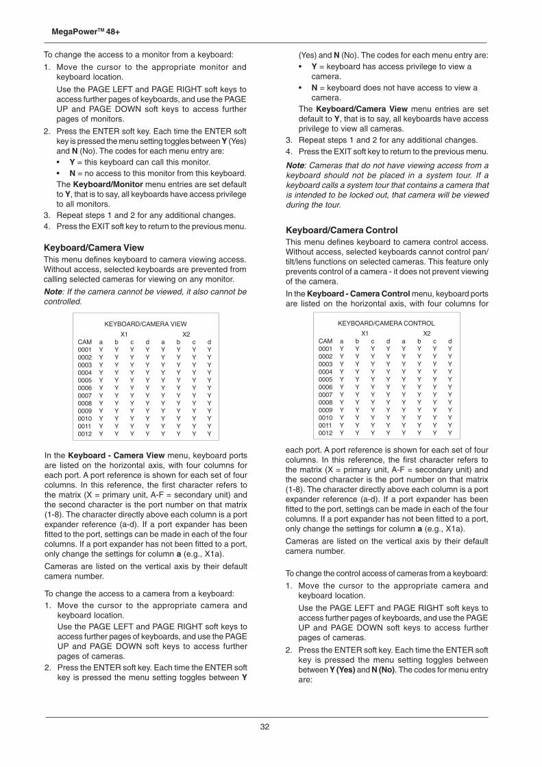
32
MegaPowerTM 48+
each port. A port reference is shown for each set of fourcolumns. In this reference, the first character refers tothe matrix (X = primary unit, A-F = secondary unit) andthe second character is the port number on that matrix(1-8). The character directly above each column is a portexpander reference (a-d). If a port expander has beenfitted to the port, settings can be made in each of the fourcolumns. If a port expander has not been fitted to a port,only change the settings for column a (e.g., X1a).
Cameras are listed on the vertical axis by their defaultcamera number.
To change the control access of cameras from a keyboard:
1. Move the cursor to the appropriate camera andkeyboard location.
Use the PAGE LEFT and PAGE RIGHT soft keys toaccess further pages of keyboards, and use the PAGEUP and PAGE DOWN soft keys to access furtherpages of cameras.
2. Press the ENTER soft key. Each time the ENTER softkey is pressed the menu setting toggles betweenbetween Y (Yes) and N (No). The codes for menu entryare:
KEYBOARD/CAMERA VIEW
X1 X2CAM a b c d a b c d0001 Y Y Y Y Y Y Y Y0002 Y Y Y Y Y Y Y Y0003 Y Y Y Y Y Y Y Y0004 Y Y Y Y Y Y Y Y0005 Y Y Y Y Y Y Y Y0006 Y Y Y Y Y Y Y Y0007 Y Y Y Y Y Y Y Y0008 Y Y Y Y Y Y Y Y0009 Y Y Y Y Y Y Y Y0010 Y Y Y Y Y Y Y Y0011 Y Y Y Y Y Y Y Y0012 Y Y Y Y Y Y Y Y
To change the access to a monitor from a keyboard:
1. Move the cursor to the appropriate monitor andkeyboard location.
Use the PAGE LEFT and PAGE RIGHT soft keys toaccess further pages of keyboards, and use the PAGEUP and PAGE DOWN soft keys to access furtherpages of monitors.
2. Press the ENTER soft key. Each time the ENTER softkey is pressed the menu setting toggles between Y (Yes)and N (No). The codes for each menu entry are:• Y = this keyboard can call this monitor.• N = no access to this monitor from this keyboard.The Keyboard/Monitor menu entries are set defaultto Y, that is to say, all keyboards have access privilegeto all monitors.
3. Repeat steps 1 and 2 for any additional changes.4. Press the EXIT soft key to return to the previous menu.
Keyboard/Camera ViewThis menu defines keyboard to camera viewing access.Without access, selected keyboards are prevented fromcalling selected cameras for viewing on any monitor.
Note: If the camera cannot be viewed, it also cannot becontrolled.
In the Keyboard - Camera View menu, keyboard portsare listed on the horizontal axis, with four columns foreach port. A port reference is shown for each set of fourcolumns. In this reference, the first character refers tothe matrix (X = primary unit, A-F = secondary unit) andthe second character is the port number on that matrix(1-8). The character directly above each column is a portexpander reference (a-d). If a port expander has beenfitted to the port, settings can be made in each of the fourcolumns. If a port expander has not been fitted to a port,only change the settings for column a (e.g., X1a).
Cameras are listed on the vertical axis by their defaultcamera number.
To change the access to a camera from a keyboard:1. Move the cursor to the appropriate camera and
keyboard location.Use the PAGE LEFT and PAGE RIGHT soft keys toaccess further pages of keyboards, and use the PAGEUP and PAGE DOWN soft keys to access furtherpages of cameras.
2. Press the ENTER soft key. Each time the ENTER softkey is pressed the menu setting toggles between Y
(Yes) and N (No). The codes for each menu entry are:• Y = keyboard has access privilege to view a
camera.• N = keyboard does not have access to view a
camera.The Keyboard/Camera View menu entries are setdefault to Y, that is to say, all keyboards have accessprivilege to view all cameras.
3. Repeat steps 1 and 2 for any additional changes.4. Press the EXIT soft key to return to the previous menu.
Note: Cameras that do not have viewing access from akeyboard should not be placed in a system tour. If akeyboard calls a system tour that contains a camera thatis intended to be locked out, that camera will be viewedduring the tour.
Keyboard/Camera ControlThis menu defines keyboard to camera control access.Without access, selected keyboards cannot control pan/tilt/lens functions on selected cameras. This feature onlyprevents control of a camera - it does not prevent viewingof the camera.
In the Keyboard - Camera Control menu, keyboard portsare listed on the horizontal axis, with four columns for
KEYBOARD/CAMERA CONTROL
X1 X2CAM a b c d a b c d0001 Y Y Y Y Y Y Y Y0002 Y Y Y Y Y Y Y Y0003 Y Y Y Y Y Y Y Y0004 Y Y Y Y Y Y Y Y0005 Y Y Y Y Y Y Y Y0006 Y Y Y Y Y Y Y Y0007 Y Y Y Y Y Y Y Y0008 Y Y Y Y Y Y Y Y0009 Y Y Y Y Y Y Y Y0010 Y Y Y Y Y Y Y Y0011 Y Y Y Y Y Y Y Y0012 Y Y Y Y Y Y Y Y
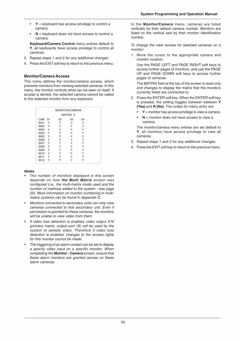
33
System Programming and Operation Manual
• Y = keyboard has access privilege to control acamera.
• N = keyboard does not have access to control acamera.
Keyboard/Camera Control menu entries default toY, all keyboards have access privilege to control allcameras.
3. Repeat steps 1 and 2 for any additional changes.
4. Press the EXIT soft key to return to the previous menu.
Monitor/Camera AccessThis menu defines the monitor/camera access, whichprevents monitors from viewing selected cameras. In thismenu, the monitor controls what can be seen on itself. Ifaccess is denied, the selected camera cannot be calledto the selected monitor from any keyboard.
Notes• The number of monitors displayed in this screen
depends on how the Multi Matrix screen wasconfigured (i.e., the multi-matrix mode used and thenumber of matrices added to the system - see page20). More information on monitor numbering in multi-matrix systems can be found in Appendix D.
• Monitors connected to secondary units can only viewcameras connected to that secondary unit. Even ifpermission is granted for these cameras, the monitorswill be unable to view video from them.
• If video loss detection is enabled, video output X16(primary matrix, output port 16) will be used by thesystem to sample video. Therefore if video lossdetection is enabled, changes to the access rightsfor this monitor cannot be made.
• The triggering of an alarm contact can be set to displaya specify video input on a specific monitor. Whencompleting the Monitor - Camera screen, ensure thatthese alarm monitors are granted access on thesealarm cameras.
In the Monitor/Camera menu, cameras are listedvertically by their default camera number. Monitors arelisted on the vertical axis by their monitor identificationnumber.
To change the view access for selected cameras on amonitor:
1. Move the cursor to the appropriate camera andmonitor location.
Use the PAGE LEFT and PAGE RIGHT soft keys toaccess further pages of monitors, and use the PAGEUP and PAGE DOWN soft keys to access furtherpages of cameras.
The MATRIX field at the top of the screen is read-onlyand changes to display the matrix that the monitorscurrently listed are connected to.
2. Press the ENTER soft key. When the ENTER soft keyis pressed, the setting toggles between between Y(Yes) and N (No). The codes for menu entry are:
• Y = monitor has access privilege to view a camera.
• N = monitor does not have access to view acamera.
The monitor/camera menu entries are set default toY, all monitors have access privilege to view allcameras.
3. Repeat steps 1 and 2 for any additional changes.
4. Press the EXIT soft key to return to the previous menu.
MONITOR/CAMERA
MATRIX X
CAM 01 02 03 040001 Y Y Y Y0002 Y Y Y Y0003 Y Y Y Y0004 Y Y Y Y0005 Y Y Y Y0006 Y Y Y Y0007 Y Y Y Y0008 Y Y Y Y0009 Y Y Y Y0010 Y Y Y Y0011 Y Y Y Y0012 Y Y Y Y
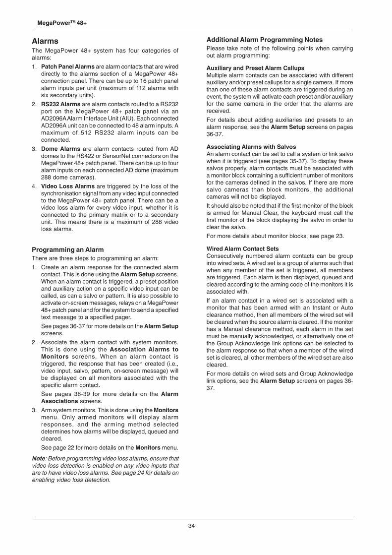
34
MegaPowerTM 48+
AlarmsThe MegaPower 48+ system has four categories ofalarms:
1. Patch Panel Alarms are alarm contacts that are wireddirectly to the alarms section of a MegaPower 48+connection panel. There can be up to 16 patch panelalarm inputs per unit (maximum of 112 alarms withsix secondary units).
2. RS232 Alarms are alarm contacts routed to a RS232port on the MegaPower 48+ patch panel via anAD2096A Alarm Interface Unit (AIU). Each connectedAD2096A unit can be connected to 48 alarm inputs. Amaximum of 512 RS232 alarm inputs can beconnected.
3. Dome Alarms are alarm contacts routed from ADdomes to the RS422 or SensorNet connectors on theMegaPower 48+ patch panel. There can be up to fouralarm inputs on each connected AD dome (maximum288 dome cameras).
4. Video Loss Alarms are triggered by the loss of thesynchronisation signal from any video input connectedto the MegaPower 48+ patch panel. There can be avideo loss alarm for every video input, whether it isconnected to the primary matrix or to a secondaryunit. This means there is a maximum of 288 videoloss alarms.
Programming an AlarmThere are three steps to programming an alarm:
1. Create an alarm response for the connected alarmcontact. This is done using the Alarm Setup screens.When an alarm contact is triggered, a preset positionand auxiliary action on a specific video input can becalled, as can a salvo or pattern. It is also possible toactivate on-screen messages, relays on a MegaPower48+ patch panel and for the system to send a specifiedtext message to a specified pager.
See pages 36-37 for more details on the Alarm Setupscreens.
2. Associate the alarm contact with system monitors.This is done using the Association Alarms toMonitors screens. When an alarm contact istriggered, the response that has been created (i.e.,video input, salvo, pattern, on-screen message) willbe displayed on all monitors associated with thespecific alarm contact.
See pages 38-39 for more details on the AlarmAssociations screens.
3. Arm system monitors. This is done using the Monitorsmenu. Only armed monitors will display alarmresponses, and the arming method selecteddetermines how alarms will be displayed, queued andcleared.
See page 22 for more details on the Monitors menu.
Note: Before programming video loss alarms, ensure thatvideo loss detection is enabled on any video inputs thatare to have video loss alarms. See page 24 for details onenabling video loss detection.
Additional Alarm Programming NotesPlease take note of the following points when carryingout alarm programming:
Auxiliary and Preset Alarm CallupsMultiple alarm contacts can be associated with differentauxiliary and/or preset callups for a single camera. If morethan one of these alarm contacts are triggered during anevent, the system will activate each preset and/or auxiliaryfor the same camera in the order that the alarms arereceived.
For details about adding auxiliaries and presets to analarm response, see the Alarm Setup screens on pages36-37.
Associating Alarms with SalvosAn alarm contact can be set to call a system or link salvowhen it is triggered (see pages 35-37). To display thesesalvos properly, alarm contacts must be associated witha monitor block containing a sufficient number of monitorsfor the cameras defined in the salvos. If there are moresalvo cameras than block monitors, the additionalcameras will not be displayed.
It should also be noted that if the first monitor of the blockis armed for Manual Clear, the keyboard must call thefirst monitor of the block displaying the salvo in order toclear the salvo.
For more details about monitor blocks, see page 23.
Wired Alarm Contact SetsConsecutively numbered alarm contacts can be groupinto wired sets. A wired set is a group of alarms such thatwhen any member of the set is triggered, all membersare triggered. Each alarm is then displayed, queued andcleared according to the arming code of the monitors it isassociated with.
If an alarm contact in a wired set is associated with amonitor that has been armed with an Instant or Autoclearance method, then all members of the wired set willbe cleared when the source alarm is cleared. If the monitorhas a Manual clearance method, each alarm in the setmust be manually acknowledged, or alternatively one ofthe Group Acknowledge link options can be selected tothe alarm response so that when a member of the wiredset is cleared, all other members of the wired set are alsocleared.
For more details on wired sets and Group Acknowledgelink options, see the Alarm Setup screens on pages 36-37.
35
System Programming and Operation Manual
Alarms MenuThe Alarms menu enables the programming of the alarmresponse for the MegaPower 48+ system. Video inputsare automatically switched to specific monitors based onexternal alarm signals triggered by alarm contacts. Analarm signal can also switch an auxiliary device on or off,and can generate a paging response that sends a textmessage to a pager at a remote location.
ALARMS
1 ALARM MESSAGES2 ALARM SETUP3 ASSOCIATE ALARMS TO MONITORS
To select an entry from the Alarms menu:
1. Move the cursor to the appropriate line or enter thenumber (1-3) for the appropriate line.
2. Press the ENTER soft key to access the selected line.
Press the EXIT soft key to return to the previous menu.
Alarm MessagesThe Alarm Messages menu enables programming of a48 character alphanumeric message on two lines fordisplay when an alarm contact is received.
ALARM MESSAGES
MESSAGE NUMBER - 128
A B C D E F G H I J K L M NO P Q R S T U V W X Y Z a bc d e f g h i j k l m n o pq r s t u v w x y z _ 0 1 23 4 5 6 7 8 9 < > : - . / ;
MESSAGE_ _ _ _ _ _ _ _ _ _ _ _ _ _ _ _ _ _ _ _ _ _ _ __ _ _ _ _ _ _ _ _ _ _ _ _ _ _ _ _ _ _ _ _ _ _ _
Alarm messages are associated with individual alarmcontacts by the four Alarm Setup menus.
A maximum of 250 alarm messages can be enteredthrough this menu for use by any alarm contacts. Eachmessage contains two lines of up to 24 characters perline.
When an alarm message is associated with an alarmcontact, and that alarm contact is armed to a monitor, themessage is displayed on the monitor when the alarmsignal is received by the system. The alarm displayremains on screen until the alarm is cleared.
Note: On-screen text display is available on primary matrixmonitors 1-8 and also on any monitors connected tosecondary matrices.
The alarm message is displayed above the camera titlein the on-screen display (Format 1) when the associatedalarm signal is received. If the on-screen display has beenlocated at the top of the monitor screen (Format 2), thatdisplay is moved down below the alarm message.
To program a message:
1. Move the cursor to the MESSAGE NUMBER line.
2. Press the ENTER soft key to cycle through theavailable message numbers until the appropriatenumber appears and then use the joystick to movethe cursor to the message line.
Alternatively, enter the appropriate message number(1-250) on the keypad and press the ENTER soft key.
3. There are two cursors in the message section of thismenu. One cursor indicates the current edit positionin the title. The other cursor, controlled by the joystick,selects the appropriate character from the display ofletters, numbers, and symbols.
To enter a title, use the joystick to move to the requiredcharacter and press the ENTER soft key to select thischaracter.
4. Repeat step 3 to key-in the appropriate title.
Note: to change an existing title, it is necessary toenter all required characters again. To remove acharacter altogether, move the cursor to theunderscore (_) character and press the ENTER softkey. You cannot backspace through the title.
Press the EXIT soft key to move to the previous menu.
Alarm SetupThe Alarm Setup menu enables the user to select thecategory of alarm to be programmed.
ALARM SETUP
1 PATCH PANEL ALARM SETUP2 RS-232 ALARM SETUP3 DOME ALARM SETUP4 VIDEO LOSS ALARM SETUP
To select a category:
1. Move the cursor to the appropriate line and press theENTER soft key, or,
2. Enter the number of the appropriate category andpress the ENTER soft key.
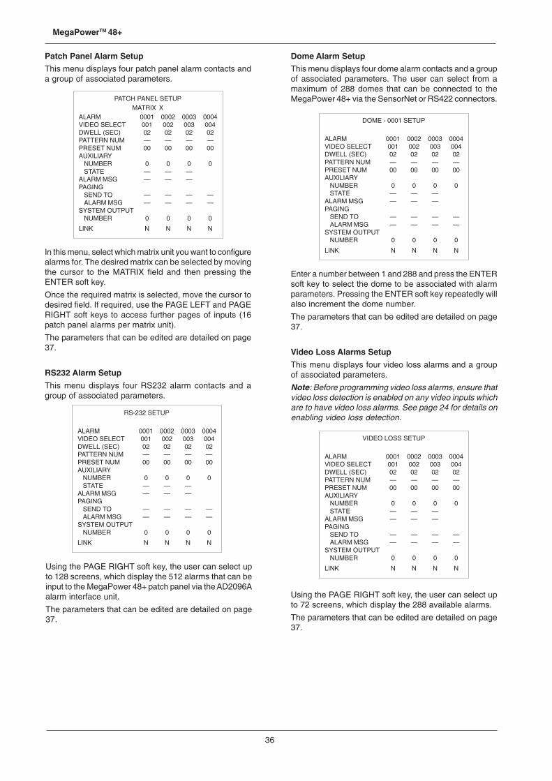
36
MegaPowerTM 48+
Patch Panel Alarm Setup
This menu displays four patch panel alarm contacts anda group of associated parameters.
PATCH PANEL SETUPMATRIX X
ALARM 0001 0002 0003 0004VIDEO SELECT 001 002 003 004DWELL (SEC) 02 02 02 02PATTERN NUM — — — —PRESET NUM 00 00 00 00AUXILIARY
NUMBER 0 0 0 0STATE — — —
ALARM MSG — — —PAGING
SEND TO — — — —ALARM MSG — — — —
SYSTEM OUTPUTNUMBER 0 0 0 0
LINK N N N N
In this menu, select which matrix unit you want to configurealarms for. The desired matrix can be selected by movingthe cursor to the MATRIX field and then pressing theENTER soft key.
Once the required matrix is selected, move the cursor todesired field. If required, use the PAGE LEFT and PAGERIGHT soft keys to access further pages of inputs (16patch panel alarms per matrix unit).
The parameters that can be edited are detailed on page37.
RS232 Alarm Setup
This menu displays four RS232 alarm contacts and agroup of associated parameters.
Dome Alarm Setup
This menu displays four dome alarm contacts and a groupof associated parameters. The user can select from amaximum of 288 domes that can be connected to theMegaPower 48+ via the SensorNet or RS422 connectors.
RS-232 SETUP
ALARM 0001 0002 0003 0004VIDEO SELECT 001 002 003 004DWELL (SEC) 02 02 02 02PATTERN NUM — — — —PRESET NUM 00 00 00 00AUXILIARY
NUMBER 0 0 0 0STATE — — —
ALARM MSG — — —PAGING
SEND TO — — — —ALARM MSG — — — —
SYSTEM OUTPUTNUMBER 0 0 0 0
LINK N N N N
Using the PAGE RIGHT soft key, the user can select upto 128 screens, which display the 512 alarms that can beinput to the MegaPower 48+ patch panel via the AD2096Aalarm interface unit.
The parameters that can be edited are detailed on page37.
DOME - 0001 SETUP
ALARM 0001 0002 0003 0004VIDEO SELECT 001 002 003 004DWELL (SEC) 02 02 02 02PATTERN NUM — — — —PRESET NUM 00 00 00 00AUXILIARY
NUMBER 0 0 0 0STATE — — —
ALARM MSG — — —PAGING
SEND TO — — — —ALARM MSG — — — —
SYSTEM OUTPUTNUMBER 0 0 0 0
LINK N N N N
Enter a number between 1 and 288 and press the ENTERsoft key to select the dome to be associated with alarmparameters. Pressing the ENTER soft key repeatedly willalso increment the dome number.
The parameters that can be edited are detailed on page37.
Video Loss Alarms Setup
This menu displays four video loss alarms and a groupof associated parameters.
Note: Before programming video loss alarms, ensure thatvideo loss detection is enabled on any video inputs whichare to have video loss alarms. See page 24 for details onenabling video loss detection.
VIDEO LOSS SETUP
ALARM 0001 0002 0003 0004VIDEO SELECT 001 002 003 004DWELL (SEC) 02 02 02 02PATTERN NUM — — — —PRESET NUM 00 00 00 00AUXILIARY
NUMBER 0 0 0 0STATE — — —
ALARM MSG — — —PAGING
SEND TO — — — —ALARM MSG — — — —
SYSTEM OUTPUTNUMBER 0 0 0 0
LINK N N N N
Using the PAGE RIGHT soft key, the user can select upto 72 screens, which display the 288 available alarms.
The parameters that can be edited are detailed on page37.
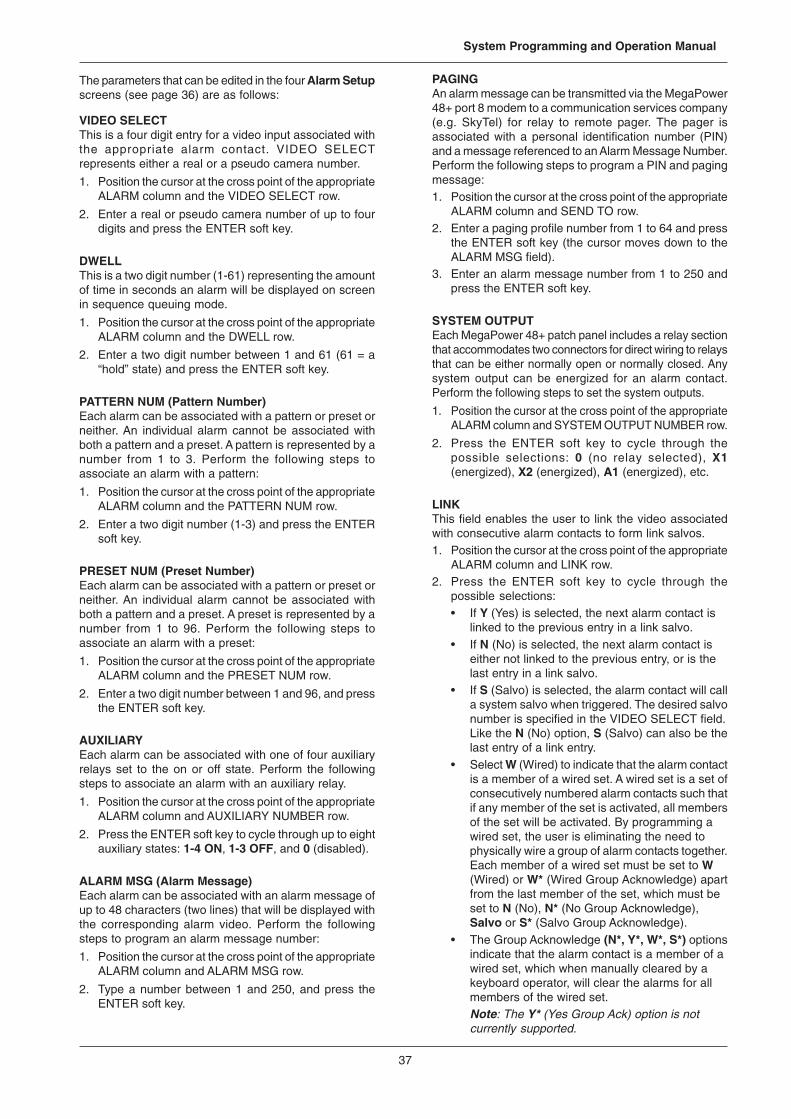
37
System Programming and Operation Manual
The parameters that can be edited in the four Alarm Setupscreens (see page 36) are as follows:
VIDEO SELECTThis is a four digit entry for a video input associated withthe appropriate alarm contact. VIDEO SELECTrepresents either a real or a pseudo camera number.
1. Position the cursor at the cross point of the appropriateALARM column and the VIDEO SELECT row.
2. Enter a real or pseudo camera number of up to fourdigits and press the ENTER soft key.
DWELLThis is a two digit number (1-61) representing the amountof time in seconds an alarm will be displayed on screenin sequence queuing mode.
1. Position the cursor at the cross point of the appropriateALARM column and the DWELL row.
2. Enter a two digit number between 1 and 61 (61 = a“hold” state) and press the ENTER soft key.
PATTERN NUM (Pattern Number)Each alarm can be associated with a pattern or preset orneither. An individual alarm cannot be associated withboth a pattern and a preset. A pattern is represented by anumber from 1 to 3. Perform the following steps toassociate an alarm with a pattern:
1. Position the cursor at the cross point of the appropriateALARM column and the PATTERN NUM row.
2. Enter a two digit number (1-3) and press the ENTERsoft key.
PRESET NUM (Preset Number)Each alarm can be associated with a pattern or preset orneither. An individual alarm cannot be associated withboth a pattern and a preset. A preset is represented by anumber from 1 to 96. Perform the following steps toassociate an alarm with a preset:
1. Position the cursor at the cross point of the appropriateALARM column and the PRESET NUM row.
2. Enter a two digit number between 1 and 96, and pressthe ENTER soft key.
AUXILIARYEach alarm can be associated with one of four auxiliaryrelays set to the on or off state. Perform the followingsteps to associate an alarm with an auxiliary relay.
1. Position the cursor at the cross point of the appropriateALARM column and AUXILIARY NUMBER row.
2. Press the ENTER soft key to cycle through up to eightauxiliary states: 1-4 ON, 1-3 OFF, and 0 (disabled).
ALARM MSG (Alarm Message)Each alarm can be associated with an alarm message ofup to 48 characters (two lines) that will be displayed withthe corresponding alarm video. Perform the followingsteps to program an alarm message number:
1. Position the cursor at the cross point of the appropriateALARM column and ALARM MSG row.
2. Type a number between 1 and 250, and press theENTER soft key.
PAGINGAn alarm message can be transmitted via the MegaPower48+ port 8 modem to a communication services company(e.g. SkyTel) for relay to remote pager. The pager isassociated with a personal identification number (PIN)and a message referenced to an Alarm Message Number.Perform the following steps to program a PIN and pagingmessage:1. Position the cursor at the cross point of the appropriate
ALARM column and SEND TO row.2. Enter a paging profile number from 1 to 64 and press
the ENTER soft key (the cursor moves down to theALARM MSG field).
3. Enter an alarm message number from 1 to 250 andpress the ENTER soft key.
SYSTEM OUTPUTEach MegaPower 48+ patch panel includes a relay sectionthat accommodates two connectors for direct wiring to relaysthat can be either normally open or normally closed. Anysystem output can be energized for an alarm contact.Perform the following steps to set the system outputs.
1. Position the cursor at the cross point of the appropriateALARM column and SYSTEM OUTPUT NUMBER row.
2. Press the ENTER soft key to cycle through thepossible selections: 0 (no relay selected), X1(energized), X2 (energized), A1 (energized), etc.
LINKThis field enables the user to link the video associatedwith consecutive alarm contacts to form link salvos.1. Position the cursor at the cross point of the appropriate
ALARM column and LINK row.2. Press the ENTER soft key to cycle through the
possible selections:• If Y (Yes) is selected, the next alarm contact is
linked to the previous entry in a link salvo.• If N (No) is selected, the next alarm contact is
either not linked to the previous entry, or is thelast entry in a link salvo.
• If S (Salvo) is selected, the alarm contact will calla system salvo when triggered. The desired salvonumber is specified in the VIDEO SELECT field.Like the N (No) option, S (Salvo) can also be thelast entry of a link entry.
• Select W (Wired) to indicate that the alarm contactis a member of a wired set. A wired set is a set ofconsecutively numbered alarm contacts such thatif any member of the set is activated, all membersof the set will be activated. By programming awired set, the user is eliminating the need tophysically wire a group of alarm contacts together.Each member of a wired set must be set to W(Wired) or W* (Wired Group Acknowledge) apartfrom the last member of the set, which must beset to N (No), N* (No Group Acknowledge),Salvo or S* (Salvo Group Acknowledge).
• The Group Acknowledge (N*, Y*, W*, S*) optionsindicate that the alarm contact is a member of awired set, which when manually cleared by akeyboard operator, will clear the alarms for allmembers of the wired set.Note: The Y* (Yes Group Ack) option is notcurrently supported.
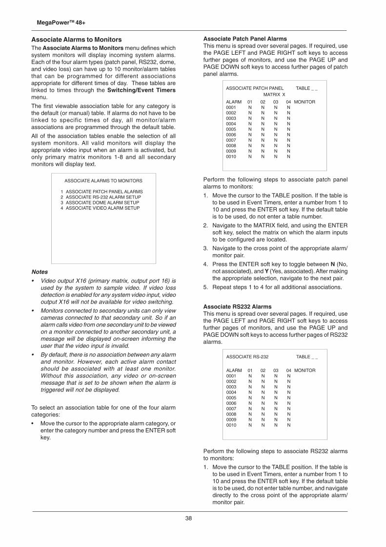
38
MegaPowerTM 48+
Associate Alarms to MonitorsThe Associate Alarms to Monitors menu defines whichsystem monitors will display incoming system alarms.Each of the four alarm types (patch panel, RS232, dome,and video loss) can have up to 10 monitor/alarm tablesthat can be programmed for different associationsappropriate for different times of day. These tables arelinked to times through the Switching/Event Timersmenu.
The first viewable association table for any category isthe default (or manual) table. If alarms do not have to belinked to specific times of day, all monitor/alarmassociations are programmed through the default table.
All of the association tables enable the selection of allsystem monitors. All valid monitors will display theappropriate video input when an alarm is activated, butonly primary matrix monitors 1-8 and all secondarymonitors will display text.
Notes• Video output X16 (primary matrix, output port 16) is
used by the system to sample video. If video lossdetection is enabled for any system video input, videooutput X16 will not be available for video switching.
• Monitors connected to secondary units can only viewcameras connected to that secondary unit. So if analarm calls video from one secondary unit to be viewedon a monitor connected to another secondary unit, amessage will be displayed on-screen informing theuser that the video input is invalid.
• By default, there is no association between any alarmand monitor. However, each active alarm contactshould be associated with at least one monitor.Without this association, any video or on-screenmessage that is set to be shown when the alarm istriggered will not be displayed.
To select an association table for one of the four alarmcategories:
• Move the cursor to the appropriate alarm category, orenter the category number and press the ENTER softkey.
Associate Patch Panel AlarmsThis menu is spread over several pages. If required, usethe PAGE LEFT and PAGE RIGHT soft keys to accessfurther pages of monitors, and use the PAGE UP andPAGE DOWN soft keys to access further pages of patchpanel alarms.
ASSOCIATE ALARMS TO MONITORS
1 ASSOCIATE PATCH PANEL ALARMS2 ASSOCIATE RS-232 ALARM SETUP3 ASSOCIATE DOME ALARM SETUP4 ASSOCIATE VIDEO ALARM SETUP
ASSOCIATE PATCH PANEL TABLE _ _MATRIX X
ALARM 01 02 03 04 MONITOR0001 N N N N0002 N N N N0003 N N N N0004 N N N N0005 N N N N0006 N N N N0007 N N N N0008 N N N N0009 N N N N0010 N N N N
Perform the following steps to associate patch panelalarms to monitors:
1. Move the cursor to the TABLE position. If the table isto be used in Event Timers, enter a number from 1 to10 and press the ENTER soft key. If the default tableis to be used, do not enter a table number.
2. Navigate to the MATRIX field, and using the ENTERsoft key, select the matrix on which the alarm inputsto be configured are located.
3. Navigate to the cross point of the appropriate alarm/monitor pair.
4. Press the ENTER soft key to toggle between N (No,not associated), and Y (Yes, associated). After makingthe appropriate selection, navigate to the next pair.
5. Repeat steps 1 to 4 for all additional associations.
Associate RS232 AlarmsThis menu is spread over several pages. If required, usethe PAGE LEFT and PAGE RIGHT soft keys to accessfurther pages of monitors, and use the PAGE UP andPAGE DOWN soft keys to access further pages of RS232alarms.
ASSOCIATE RS-232 TABLE _ _
ALARM 01 02 03 04 MONITOR0001 N N N N0002 N N N N0003 N N N N0004 N N N N0005 N N N N0006 N N N N0007 N N N N0008 N N N N0009 N N N N0010 N N N N
Perform the following steps to associate RS232 alarmsto monitors:
1. Move the cursor to the TABLE position. If the table isto be used in Event Timers, enter a number from 1 to10 and press the ENTER soft key. If the default tableis to be used, do not enter table number, and navigatedirectly to the cross point of the appropriate alarm/monitor pair.
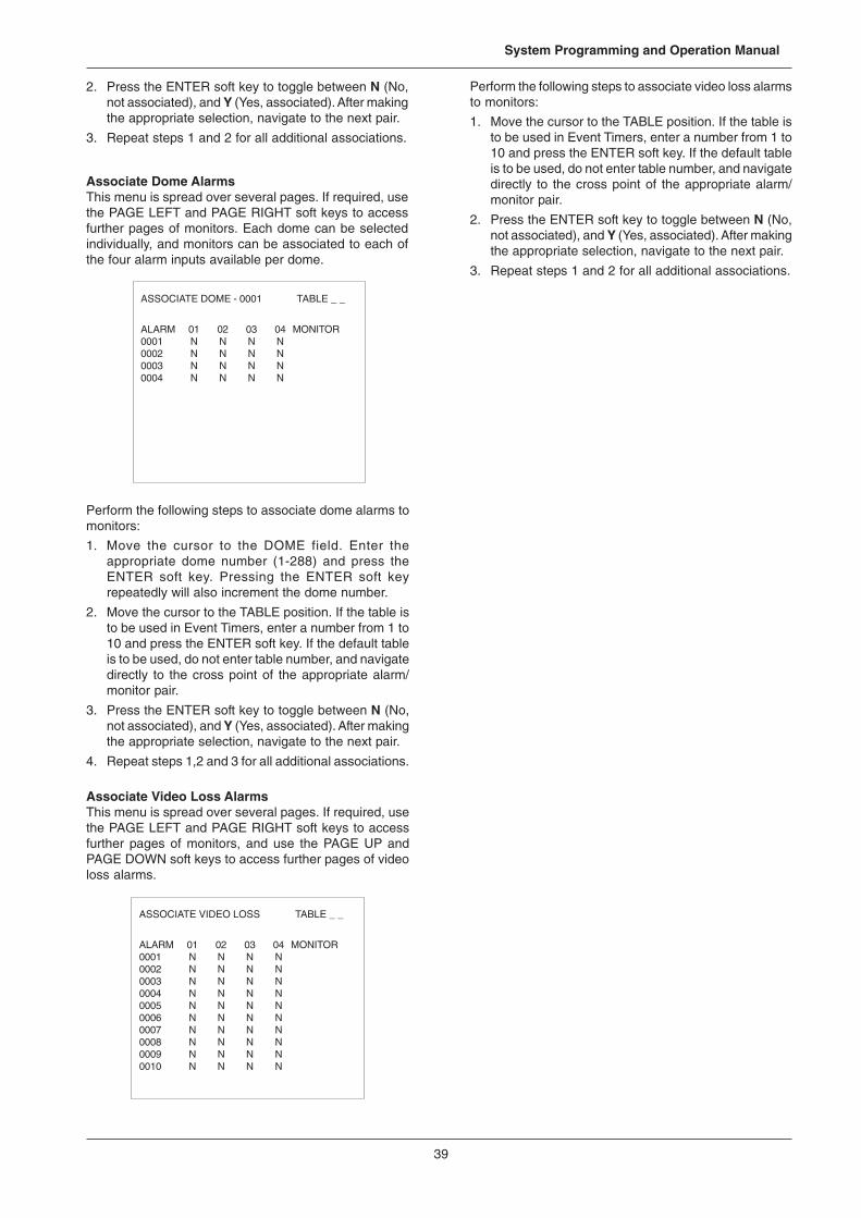
39
System Programming and Operation Manual
2. Press the ENTER soft key to toggle between N (No,not associated), and Y (Yes, associated). After makingthe appropriate selection, navigate to the next pair.
3. Repeat steps 1 and 2 for all additional associations.
Associate Dome AlarmsThis menu is spread over several pages. If required, usethe PAGE LEFT and PAGE RIGHT soft keys to accessfurther pages of monitors. Each dome can be selectedindividually, and monitors can be associated to each ofthe four alarm inputs available per dome.
Perform the following steps to associate video loss alarmsto monitors:
1. Move the cursor to the TABLE position. If the table isto be used in Event Timers, enter a number from 1 to10 and press the ENTER soft key. If the default tableis to be used, do not enter table number, and navigatedirectly to the cross point of the appropriate alarm/monitor pair.
2. Press the ENTER soft key to toggle between N (No,not associated), and Y (Yes, associated). After makingthe appropriate selection, navigate to the next pair.
3. Repeat steps 1 and 2 for all additional associations.
ASSOCIATE DOME - 0001 TABLE _ _
ALARM 01 02 03 04 MONITOR0001 N N N N0002 N N N N0003 N N N N0004 N N N N
Perform the following steps to associate dome alarms tomonitors:
1. Move the cursor to the DOME field. Enter theappropriate dome number (1-288) and press theENTER soft key. Pressing the ENTER soft keyrepeatedly will also increment the dome number.
2. Move the cursor to the TABLE position. If the table isto be used in Event Timers, enter a number from 1 to10 and press the ENTER soft key. If the default tableis to be used, do not enter table number, and navigatedirectly to the cross point of the appropriate alarm/monitor pair.
3. Press the ENTER soft key to toggle between N (No,not associated), and Y (Yes, associated). After makingthe appropriate selection, navigate to the next pair.
4. Repeat steps 1,2 and 3 for all additional associations.
Associate Video Loss AlarmsThis menu is spread over several pages. If required, usethe PAGE LEFT and PAGE RIGHT soft keys to accessfurther pages of monitors, and use the PAGE UP andPAGE DOWN soft keys to access further pages of videoloss alarms.
ASSOCIATE VIDEO LOSS TABLE _ _
ALARM 01 02 03 04 MONITOR0001 N N N N0002 N N N N0003 N N N N0004 N N N N0005 N N N N0006 N N N N0007 N N N N0008 N N N N0009 N N N N0010 N N N N

40
MegaPowerTM 48+
Keys Function
1-F1 Unlocks the current camera
2-F1 Locks the current camera
1-F2 Sets on-screen time & date display ON
2-F2 Sets on-screen time & date display OFF
3-F2 Sets camera title, number, & status display ON
4-F2 Sets camera title, number, & status display OFF
5-F2 Displays titles, date, & time at alternate screen location
6-F2 Displays titles, date, & time at primary screen location
7-F2 Sets on-screen time, date, & title display ON
8-F2 Sets on-screen time, date, & title display OFF
21-F2 Sets time & date format to month/day/year
22-F2 Sets time & date format to day/month/year
23-F2 Sets time & date format to year/month/day
24-F2 Steps through date formats
45-F2 Disables bell at keyboard for all RS232 ports
46-F2 Enables bell at keyboard for all RS232 ports
47-F2 Disables bell signal sent to one keyboard port
48-F2 Enables bell signal sent to one keyboard port
50-F2 Start title positioning
51-F2 Stop title positioning
55-F2, 99-F2 System Reset (99-F2 must follow 55-F2 within 3 second interval)
55-F2, 140-F2 System Data Transfer – CPU to memory module (140-F2 must follow 55-F2 within 3 second interval)
55-F2, 141-F2 System Data Transfer – memory module to CPU (141-F2 must follow 55-F2 within 3 second interval)
60-F2 Displays current day of week
70-F2 Displays software version number
100-F2 Sets video loss mode to OFF for called camera
101-F2 Sets video loss mode to ON for called camera
105-F2 Sets video loss automatically for called camera
106-F2 Sets video loss automatically for all cameras
108-F2 Clears video loss settings for all cameras
111-F2 Prints current video loss setting for called camera
112-F2 Prints current video loss setting for all cameras
Appendix A: Special Function Key CommandsThe F1 and F2 keys on the ADCC1100, ADCC0200, ADCC0300, AD2079, AD2088 and ADTTE keyboards are specialfunction keys which, when used in combination with numeric keypad inputs, accomplish specific functions within the MegaPower48+ system. Following is a listing of F1 and F2 key combinations and their associated functions.
Note: F2 commands can also be used to arm and disarm monitors. See page 11 for more details.

41
System Programming and Operation Manual
Keys Function
19-F1 Flip Camera Position 180º
20-F1 Reset Iris
38-F2 Enter Vertical Phase Adjust Mode
39-F2 Exit Vertical Phase Adjust Mode
30-F1 Reset Dome
69-F1 Return to Auto Iris / Auto Focus
120-F2 End Pattern Definition
121-F2 Define Pattern # 1
122-F2 Define Pattern # 2
123-F2 Define Pattern # 3
130-F2 Save New Pattern
131-F2 Clear Pattern # 1 (SpeedDome RS422)
132-F2 Clear Pattern # 2 (SpeedDome RS422)
133-F2 Clear Pattern # 3 (SpeedDome RS422)
31-F1 Go to Pattern # 1
32-F1 Go to Pattern # 2
33-F1 Go to Pattern # 3
21-F1 Run Pattern # 1
22-F1 Run Pattern # 2
23-F1 Run Pattern # 3
41-F1 Auto Repeat Pattern # 1
42-F1 Auto Repeat Pattern # 2
43-F1 Auto Repeat Pattern # 3
Appendix B: SpeedDome Series Programmable CommandsWhen used in combination with numeric keypad inputs, the F1 and F2 keys on the ADCC1100, ADCC0200, ADCC0300,AD2079, AD2088 and ADTTE keyboards accomplish specific functions related to the operation of SpeedDome series domes.Following is a list of F1 and F2 key combinations and their associated functions.
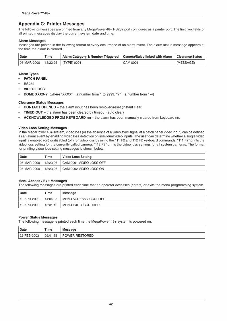
42
MegaPowerTM 48+
Date Time Alarm Category & Number Triggered Camera/Salvo linked with Alarm Clearance Status
05-MAR-2000 13:23:26 (TYPE) 0001 CAM 0001 (MESSAGE)
Date Time Video Loss Setting
05-MAR-2000 13:23:26 CAM 0001 VIDEO LOSS OFF
05-MAR-2000 13:23:26 CAM 0002 VIDEO LOSS ON
Date Time Message
12-APR-2003 14:04:35 MENU ACCESS OCCURRED
12-APR-2003 15:31:12 MENU EXIT OCCURRED
Date Time Message
22-FEB-2003 09:41:35 POWER RESTORED
Appendix C: Printer MessagesThe following messages are printed from any MegaPower 48+ RS232 port configured as a printer port. The first two fields ofall printed messages display the current system date and time.
Alarm MessagesMessages are printed in the following format at every occurrence of an alarm event. The alarm status message appears atthe time the alarm is cleared.
Alarm Types• PATCH PANEL
• RS232
• VIDEO LOSS
• DOME XXXX-Y (where “XXXX” = a number from 1 to 9999. “Y” = a number from 1-4)
Clearance Status Messages• CONTACT OPENED – the alarm input has been removed/reset (instant clear)
• TIMED OUT – the alarm has been cleared by timeout (auto clear)
• ACKNOWLEDGED FROM KEYBOARD nn – the alarm has been manually cleared from keyboard nn.
Video Loss Setting MessagesIn the MegaPower 48+ system, video loss (or the absence of a video sync signal at a patch panel video input) can be definedas an alarm event by enabling video loss detection on individual video inputs. The user can determine whether a single videoinput is enabled (on) or disabled (off) for video loss by using the 111 F2 and 112 F2 keyboard commands. “111 F2” prints thevideo loss setting for the currently called camera. “112 F2” prints the video loss settings for all system cameras. The formatfor printing video loss setting messages is shown below:
Menu Access / Exit MessagesThe following messages are printed each time that an operator accesses (enters) or exits the menu programming system.
Power Status MessagesThe following message is printed each time the MegaPower 48+ system is powered on.

43
System Programming and Operation Manual
Appendix D: Monitor Identification NumbersThe following table shows how monitors are numbered in the MegaPower 48+ system. The numbering is dependant on themulti-matrix mode (0-3) that is in use and the number of secondary matrices that have been connected. See page 20 formore details on multi-matrix configuration.
Monitor numbering is shown in relation to the video output ports to which monitors are connected. Video output ports areshown by port reference. In this reference, the first character is the matrix reference (X = primary unit, A-F = secondary units)and the second character is the RS232 port number (1-8) on that matrix.
Multi-Matrix Mode Number of Secondaries Monitor Numbers Video Output Ports Used
0 0 1-16 X1-X16
1 1 1-16 X1-X16
2 1-16 X1-X16
3 1-16 X1-X16
2 1 1-12 X1-X1213-15 A1-A3
2 1-12 X1-X1213-15 A1-A316-18 B1-B3
3 1-12 X1-X1213-15 A1-A316-18 B1-B319-21 C1-C3
4 1-12 X1-X1213-15 A1-A316-18 B1-B319-21 C1-C322-24 D1-D3
3 1 1-8 X1-X89-15 A1-A7
2 1-8 X1-X89-15 A1-A716-22 B1-B7
3 1-8 X1-X89-15 A1-A716-22 B1-B723-29 C1-C7
4 1-8 X1-X89-15 A1-A716-22 B1-B723-29 C1-C730-36 D1-D7
5 1-8 X1-X89-15 A1-A716-22 B1-B723-29 C1-C730-36 D1-D737-43 E1-E7
6 1-8 X1-X89-15 A1-A716-22 B1-B723-29 C1-C730-36 D1-D737-43 E1-E744-50 F1-F7

44
MegaPowerTM 48+
Appendix E: Software License Agreement1. General. Software is being licensed to the Customer pursuant to the following terms and conditions, which supplement
any purchase or lease agreement (the “Equipment Agreement”) between Customer and Sensormatic ElectronicsCorporation (“SEC”). By accepting receipt of, or by using, such Software, the Customer agrees to be bound by the termsof this Software License Agreement (the “License Agreement”). The term “Software” means all computer programs,instructions, data and databases, in any form or on any media, supplied by SEC (or its suppliers) to Customer and allcurrent and future versions, revisions, updates, upgrades and new releases thereof. Except as otherwise provided in thisLicense Agreement, the terms and conditions of the Equipment Agreement apply to the Software, the related technicaland user manuals (“Documentation”) and the license provided herein.
2. License. SEC licenses the Software and the Documentation to Customer, for the license fee(s) set forth (or included inthe product prices set forth) in the Equipment Agreement and subject to the terms and conditions of this License Agreement.The license is non-exclusive and is limited by the terms of this License Agreement. Customer may not transfer thelicense except to a party to whom the equipment is transferred and then only with the written consent of SEC. TheSoftware and Documentation are being licensed and not sold or leased to Customer. SEC or its suppliers who haveauthorized SEC to sublicense certain of the Software and Documentation retain ownership of the Software andDocumentation. The Software is being licensed for use only on (i) a single computer (A) owned or leased by Customerand identified in the Equipment Agreement or (B) otherwise identified in the Documentation as compatible with theSoftware, or (ii) a back-up machine if and so long as such computer becomes temporarily inoperable.
3. Term. The term of the license is perpetual, except that it will terminate automatically if Customer sells or otherwisedisposes of the Software or its related equipment or Customer breaches any provision of this License Agreement or theEquipment Agreement. If the license terminates, SEC will have the right to take possession of all copies of the Softwareand Documentation in the possession of Customer or to require Customer to destroy all such copies and certify suchdestruction in writing to SEC.
4. Ownership. Customer agrees and acknowledges that (i) SEC (or its suppliers) is the sole owner of the Software andDocumentation (including all copies thereof, in whatever form or media, delivered to or made by Customer) and allpatent, copyright and other intellectual property rights with respect thereto and (ii) the Software and Documentationconstitute valuable trade secrets, confidential information and proprietary properties of SEC and its suppliers. Accordingly,Customer agrees that it will have no rights in the Software or Documentation other than those granted under this LicenseAgreement and agrees to abide by the restrictions on its use of the Software and Documentation set forth in Section 5 ofthis License Agreement.
5. Use and Copies. Customer may use the Software and Documentation only in conjunction with the other equipmentidentified in the Equipment Agreement, as part of the access control, closed circuit television or other security systembeing acquired from SEC and for Customer’s internal business purposes. SEC will furnish the Software to Customersolely in object code form.
Customer may make up to 2 copies of the Software solely for back-up and archival purposes. Customer will not removeor modify the copyright and other proprietary notices and legends of SEC and its suppliers contained in the Software andDocumentation and will reproduce all such notices and legends on all copies of the Software made by Customer. Customermay not make copies of the Documentation, but may obtain additional copies of the Documentation from SEC at itsestablished rates. Except as permitted above, copying of the Software and Documentation is forbidden.
Customer will not sell, assign, sublicense or transfer this license or sell or otherwise transfer the Software or Documentation(or any portion thereof) to others. Customer will maintain the Software and Documentation in confidence and not discloseany data or other information contained in the Software or Documentation to any party, except for Customer’s employeesand agents who require access to the Software for the purposes of Customer’s internal business and who use it inaccordance with the terms of this License Agreement. Customer will not use the Software for the provision of time-sharing services to others. Customer will not modify the Software or decompile, disassemble or otherwise reverse engineerthe Software and will not have the right to create derivative works of the Software, including, without limitation, translatedor localized versions of the Software. Customer will not export or re-export the Software or the Documentation or anyportion thereof without appropriate United States or foreign governmental licenses.
Customer will implement appropriate measures, such as the requirement that employees and others permitted access tothe Software enter into appropriate non-disclosure agreements, to satisfy its obligations hereunder and, generally, willtreat the Software and Documentation with the same degree of care and confidentiality which Customer provides for itsown confidential information. Customer acknowledges that it may be held legally responsible for any copyright infringementor trade secret violation that is caused, in whole or in part, by its failure to abide by the terms of this License Agreement.Since unauthorized transfer, use or disclosure of the Software and Documentation would diminish their value to SEC andits suppliers, who would have no adequate remedy at law if Customer breaches its obligations under this License Agreement,SEC and its suppliers (who are direct and intended beneficiaries of this License Agreement) will be entitled to injunctiverelief, in addition to such other remedies and relief that would be available to them in the event of such a breach.

45
System Programming and Operation Manual
6. Limited Warranty; Limitation of Liability. The provisions of the Equipment Agreement respecting maintenance andwarranty will not apply to the Software or the Documentation, unless specifically stated otherwise and agreed to in writingby both parties. SEC’s sole warranties with respect to the Software and Documentation are that (i) SEC has title to theSoftware and Documentation and/or the right to grant Customer the license set forth in this License Agreement and (ii)the magnetic media on which the Software is recorded is free from defects in materials and workmanship under normaluse. SEC’s sole obligation under this warranty will be to replace any defective media returned to it free of charge. Theperiod of this warranty will be 12 months from the date of the Equipment Agreement (the “Warranty Period”).
EXCEPT AS SET FORTH IN THIS SECTION 6, SEC DISCLAIMS ANY WARRANTY, EXPRESS OR IMPLIED, WITHRESPECT TO THE SOFTWARE OR THE DOCUMENTATION OR THEIR OPERATION OR USE, INCLUDING, WITHOUTLIMITATION, ANY IMPLIED WARRANTY OF MERCHANTABILITY OR OF FITNESS FOR A PARTICULAR PURPOSEOR USE. SOME STATES DO NOT ALLOW THE EXCLUSION OF IMPLIED WARRANTIES, SO THE ABOVE EXCLUSIONDOES NOT APPLY IN SUCH STATES. THIS WARRANTY GIVES YOU SPECIFIC LEGAL RIGHTS, AND YOU MAYALSO HAVE OTHER RIGHTS THAT VARY FROM STATE TO STATE.
SEC AND ITS SUPPLIERS, EMPLOYEES, AGENTS AND FRANCHISEES WILL IN NO EVENT BE LIABLE FOR ANYINCIDENTAL, CONSEQUENTIAL OR OTHER DIRECT OR INDIRECT DAMAGES (FOR LOSS OF BUSINESSINFORMATION OR PROFITS OR OTHERWISE) SUFFERED BY CUSTOMER, ANY OF ITS EMPLOYEES OR AGENTSOR ANY OTHER PERSON ARISING OUT OF OR IN CONNECTION WITH THE USE OR INABILITY TO USE THESOFTWARE OR THE DOCUMENTATION, OR THE MAINTENANCE OR SUPPORT THEREOF, EVEN IF THEY HAVEBEEN ADVISED OF THE POSSIBILITY OF SUCH DAMAGES. SEC neither assumes nor authorizes any employee,agent or franchisee to assume for SEC any other liability in connection with the license, use or performance of theSoftware or Documentation.
Customer is solely responsible for the selection of the Software to achieve Customer’s intended results, for the conformityof the computer on which the Software is run to SEC’s specifications or requirements and for the maintenance of suchcomputer in good working order and repair. SEC’s suppliers do not warrant the Software, assume any liability regardingthe use of the Software or undertake to provide any maintenance, support or information regarding the Software.
7. U.S. Government Restricted Rights. The Software and Documentation are provided with restricted rights. Use, duplicationor disclosure by the U.S. Government is subject to restrictions as set forth in subparagraphs (c)(1)(ii) of the Rights inTechnical Data and Computer Software Clause of Department of Defense Federal Acquisition Supplement (DFARS)252.227-7013 or in subparagraph (g)(3)(i) of Federal Acquisition Regulations (FAR) 52.227-14, Alternate III, as applicable.
8. Indemnity. SEC will defend and hold Customer harmless from any claim, action, suit or proceeding brought againstCustomer to the extent that it is based on a claim that the use of the Software, as such, in accordance with this LicenseAgreement and not as a result of the combination thereof with any other article, computer software or process, constitutesan infringement of any United States patent or copyright or the violation of any trade secret, if SEC is notified thereofpromptly after its commencement and is given control of the defense thereof and any negotiations for its settlement andfull cooperation by Customer.
SEC will pay all damages and costs awarded against Customer in connection with any such claim, except that SEC willnot be liable for any amounts paid under any compromise or settlement made without its consent. If the Software is eitherclaimed or held to infringe or violate any patent or copyright, SEC may, at its sole option and expense, and Customer willpermit SEC to, procure for Customer the right to continue using the Software or modify it so that it becomes non-infringing or replace it with a non-infringing counterpart. If neither of such alternatives is available on terms which arereasonable in SEC’s judgment, Customer will return all copies of the Software and Documentation in the possession ofCustomer to SEC, at SEC’s request, and SEC will refund a reasonable portion of the license fees paid by Customer toSEC. This Section 8 sets forth SEC’s entire liability regarding infringement and the like.

46
MegaPowerTM 48+

47
System Programming and Operation Manual

Please visit our website for more informationwww.americandynamics.net
© 2004 American DynamicsProduct specifications subject to change without noticeCertain product names mentioned herein may be trade namesand/or registered trademarks of other companies MP-48PROG-HB-1