Embed Size (px)
Citation preview

Mega-Classic™
Operator’sManual
Pure Water, Inc.3725 Touzalin Ave.Lincoln, NE 68507
Phone: 402-467-9300 • Fax: 402-467-9393

Table of Contents
Important Safety Information ................................................................................ 3
Introduction ...................................................................................................................... 4
Record Important Information .............................................................................. 4
Included With Your Distiller ................................................................................... 4
Optional Accessories ................................................................................................... 5
How Your Distiller Works ......................................................................................... 6
Preparing for Installation .......................................................................................... 7
Installation......................................................................................................................... 8
Connecting the Incoming Water Line ........................................................ 8
Connecting the Boiling Tank Drain Line & Overflow Line ........ 10
Connect the Distilled Water Line and Faucet .................................... 11
Start-Up ............................................................................................................................ 12
Sterilizing ................................................................................................................. 12
Post Filter Installation ...................................................................................... 12
Maintenance and Cleaning ................................................................................... 15
Overall Maintenance Requirements ........................................................ 15
Cleaning the Boiling Tank ............................................................................. 15
Changing the Post Filter ................................................................................. 16
Assembly of the Optional Cart/Floor Stand ............................................... 17
Troubleshooting .......................................................................................................... 18
Electrical Schematic ................................................................................................. 21
Exploded View ............................................................................................................. 22
Parts .................................................................................................................................... 2222222222
page 2 Mega-Classic Owners Manual

Mega-Classic Owners Manual page 3
Important Safety Information
♦ If you are not sure that your electrical outlet is properly grounded or that the circuit
protection is correct, have it checked by a qualified electrician.
♦ Operate indoors only.
♦ The area MUSTMUSTMUSTMUSTMUST be well ventilated.
♦ WARNING: WARNING: WARNING: WARNING: WARNING: Disconnect the distiller from the power supply before assembling,
adjusting or servicing the distiller.
♦ NEVER NEVER NEVER NEVER NEVER immerse the distiller in water or any other liquid.
♦ NEVER NEVER NEVER NEVER NEVER operate the distiller with a damaged cord or allow the cord to become
exposed to hot surfaces.
♦ DO NOT DO NOT DO NOT DO NOT DO NOT use an extension cord or adapters.
♦ DO NOT DO NOT DO NOT DO NOT DO NOT let children play with the distiller.
♦ DO NOT DO NOT DO NOT DO NOT DO NOT touch the top of the distiller when it is operating because it becomes very
hot.
♦ Exercise care when removing the boiling tank lid and never remove it when the
distiller is operating.
♦ The installation and use of this product must comply with all applicable state and
local laws and regulations.
♦ IMPORTANT:IMPORTANT:IMPORTANT:IMPORTANT:IMPORTANT: This distiller is designed to be used only with Pure Water, Inc.
accessories and replacement components.
♦ This distiller is equipped with fused pump circuitry. In the event of pump failure,
check the pump fuse located on the panel under the switches. Replace only with a
1 amp Slo-Blo fuse. Never use any fuse larger than specified.
♦ NEVER NEVER NEVER NEVER NEVER have the unit in the Auto Drain mode if an auto drain connection is absent.
♦ The physiological effects of the operation of this distiller, beneficial or otherwise
have not been investigated by U.L.
♦ This distiller conforms to ANSI/NSF Standard 62 for the following reduction claims:
TDS Reduction Arsenic Reduction
Fluoride Reduction Barium Reduction
Lead Reduction Cadmium Reduction
Mercury Reduction Chromium (hexavalent) Reduction
Selenium Reduction Chromium (trivalent) Reduction
Copper Reduction
♦ Operating Pressure 30-100 PSI
♦ Mega-Classic produces 12 gallons per day (.5 gallons per hour) under normal
operating conditions
Introduction
Congratulations on purchasing the finest home water distillation system on the market.
With proper care and attention, the Mega-Classic will give you many years of top
performance and high-quality drinking water. Please read this manual thoroughly before
installing and operating your Mega-Classic.
Record Important Information
The model and serial number are found on the back panel. You should record the
serial number below for future references.
Date of Purchase:
Model:
Serial Number:
Purchased from:
Included With Your Distiller
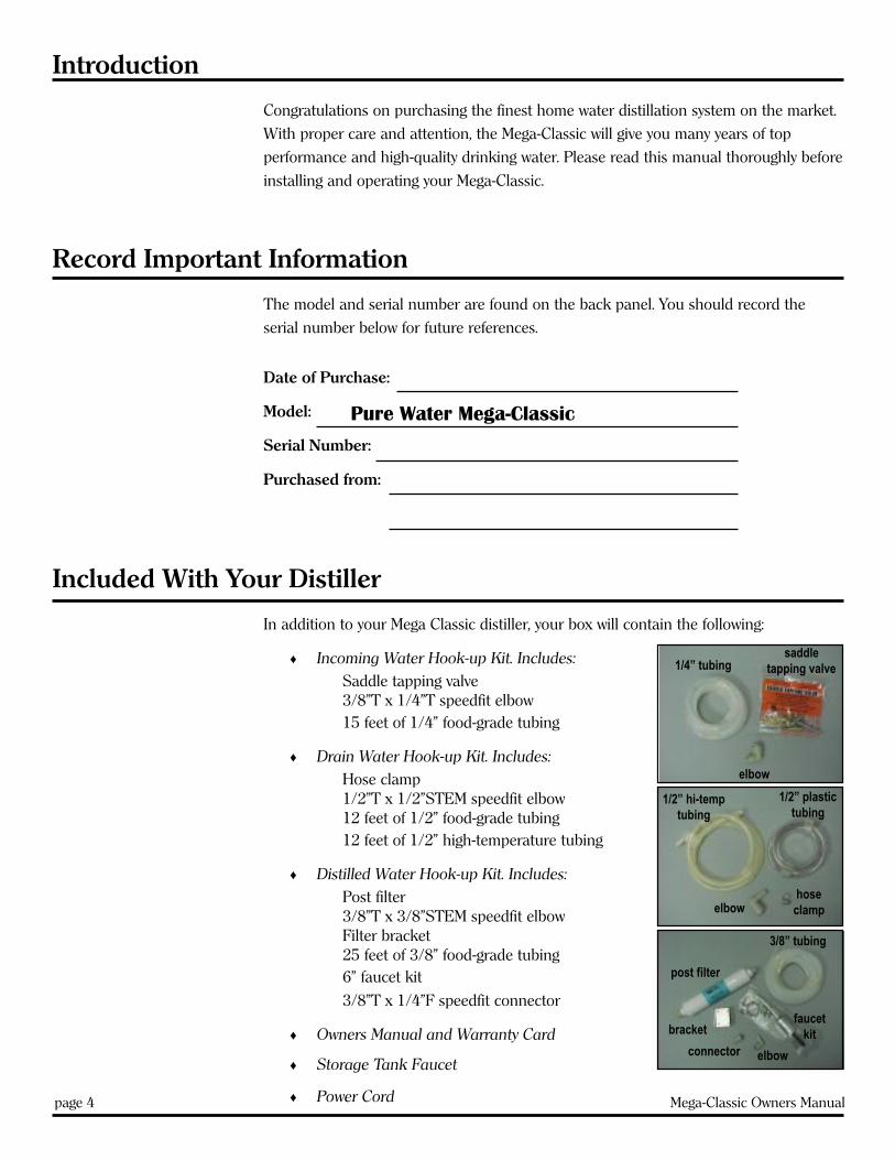
In addition to your Mega Classic distiller, your box will contain the following:
♦ Incoming Water Hook-up Kit. Includes:Saddle tapping valve3/8”T x 1/4”T speedfit elbow15 feet of 1/4” food-grade tubing
♦ Drain Water Hook-up Kit. Includes:Hose clamp1/2”T x 1/2”STEM speedfit elbow12 feet of 1/2” food-grade tubing12 feet of 1/2” high-temperature tubing
♦ Distilled Water Hook-up Kit. Includes:Post filter3/8”T x 3/8”STEM speedfit elbowFilter bracket25 feet of 3/8” food-grade tubing6” faucet kit
3/8”T x 1/4”F speedfit connector
♦ Owners Manual and Warranty Card
♦ Storage Tank Faucet
♦ Power Cordpage 4 Mega-Classic Owners Manual
Pure Water Mega-Classic
1/4” tubingsaddle
tapping valve
elbow
elbowhoseclamp
1/2” hi-temptubing
1/2” plastictubing
bracket
3/8” tubing
faucetkit
post filter
elbowconnector

Mega-Classic Owners Manual page 5
Optional Accessories
The following are optional accessories or maintenance items for the Mega-Classic. They
may be purchased from your Dealer or Distributor, or directly from Pure Water, Inc.
♦ Mega-Classic Cart/Floor stand with castors for ease of use, cleaning and service.
Also allows for proper positioning for draining the boiling and storage tanks.
Stock #36996.
♦ Auxiliary hook-up kit for running distilled water to your refrigerator or icemaker.
Stock #4540.
♦ Pressure tank hook-up kit to protect the pump when using with multiple
dispensers. Stock #19001(tank) and #9523 (fittings).
♦ Lumen™ cleaner and descaler for cleaning the boiling tank. Stock #6603.
♦ Stainless steel polish. Stock #6606.
♦ Post-filter replacement cartridge. Stock #32513.
♦ Extended-reach faucet for your sink (an option from the standard 6” faucet).
Stock #95304K.

page 6 Mega-Classic Owners Manual
How Your Distiller Works
The Mega-Classic is designed to produce approximately one gallon of high-quality, pure
distilled water every two hours, or up to twelve gallons in a 24-hour period.
The Mega-Classic is a fully automatic unit. The water level in the boiling tank and
storage tank are controlled by individual floats and a set of microswitches.
The boiling tank operates on a modified batch approach. Feedwater is automatically
added until a high level is reached and this triggers the heating element and fan to
operate. This begins the distillation cycle.
As the unit distills, the water level in the boiling tank falls. When the water level gets
close to the heating element, the low-level microswitch is triggered, causing feedwater to
be added until the high level is reached. If, for some reason, no water enters the boiling
tank when needed, the fan and heating element will remain off until the condition is
corrected.
Once the storage tank is full of distilled water, the unit will automatically shut down and
the contents of the boiling tank are drained by the automatic drain valve, thereby
flushing out most of the contaminants from the boiling tank. If a drain is not available
for automatic draining, the unit can be set to drain manually.
The Mega-Classic will begin distilling again once the water level in the storage tank
drops to approximately 3/4 full. It continues to operate until the storage tank is full
again.
The built-in demand pump allows distilled water to be delivered to a faucet, chilled/hot
water dispenser, refrigerator, icemaker or other locations as desired.
Safety Feature
An overflow sensor isinstalled in the driptray of your distiller inthe unlikely event thata leak or an overflowsituation occurs inyour distiller. Your unitwill automatically shutdown when the switchsenses a certain levelof water in the driptray.
Special Feature
An Hour Meter isinstalled on yourMega-Classic. This willallow you to track theoperation and assistwith schedulingmaintenance.

Mega-Classic Owners Manual page 7
Preparing For Installation
Before proceeding with the installation, you must determine the mode of operation
(Auto Drain Mode or Manual Drain Mode). Pure Water, Inc. recommends that your
Mega-Classic be operated in the Auto Drain Mode, but we recognize that all locations
may not have an adequate drain available.
Auto Drain Mode: Auto Drain Mode: Auto Drain Mode: Auto Drain Mode: Auto Drain Mode: This allows the boiling tank of the distiller to drain automati-
cally when the storage tank is full or when there is a power interruption. In the
Auto Drain Model, the Mega-Classic needs to be installed in a location with an
appropriate drain and drain connections, as explained in the Connecting the
Boiling Tank Drain Line section on page 10 of this manual. The Drain OperationThe Drain OperationThe Drain OperationThe Drain OperationThe Drain Operation
Switch is preset at the factory to the “Auto” mode.Switch is preset at the factory to the “Auto” mode.Switch is preset at the factory to the “Auto” mode.Switch is preset at the factory to the “Auto” mode.Switch is preset at the factory to the “Auto” mode.
Manual Drain Mode: Manual Drain Mode: Manual Drain Mode: Manual Drain Mode: Manual Drain Mode: This allows the boiling tank to be drained manually. This is
ideal for locations that do not have an appropriate drain or connection. Manual
Drain Mode will not allow the unit to drain the boiling tank automatically. If you
wish to set your drain mode to manual, you must remove the side panel and
locate the Drain Operation Switch on the side of the unit and change it to
“Manual”. Note::::: When draining the boiling tank manually, you must depress and
hold the Drain Switch in the “Override” position. This switch is located under the
top panel. . . . . You must also turn the Function Switch to “Clean”. Make sure you
return the Function Switch to “Distill” once manual draining is complete.
Other things to consider when installing your Mega-Classic:
♦ Select an area that will allow the distiller to remain level. Improper leveling
could affect the production rate.
♦ The distiller must be located in close proximity to a water supply, floor or other
drain and appropriate electrical supply source. The distiller should also be
located in a well ventilated room.
♦ The Mega-Classic should be installed at least two feet above the floor. This is
for several reasons:
1. Easier position to observe and maintain.
2. Better drainage from the boiling tank when it dumps the residue water.
♦ Electrical requirements: Isolated 115 VAC, 20 amp circuit (220 VAC, 10 amp).
Check the electrical rating on the label on the rear of the distiller.
♦ When connecting the tubing into the quick-connect fittings, it is critical the
tubing be inserted fully! The tubing should insert into the fitting 1/2” to 3/4”.
Failure to do so could cause water damage. We recommend that prior to
inserting the tubing, you mark the tubing 1/2” from the end being inserted into
the fitting, then pull back on the tubing to verify it is attached securely. This
should ensure the tubing is properly and fully installed. Also, make sure the
tubing is cut squarely and is free of rough edges.
Note: The use ofsoftened water isrecommended tominimize scalebuild-up in the
automatic drain valve.

page 8 Mega-Classic Owners Manual
Installation
CAUTION: : : : : The Mega Classic weighs approximately 75 lbs. Follow these instructions
to prevent injury.
1. Open the carton from the bottom by cutting along the dotted line with a utility
knife.
2. Carefully slide the carton up so the distiller is in the upright position when the
carton is removed.
3. Remove and identify all parts kits as listed on page 4.
Connecting the Incoming Water Line
Notes and Cautions:
Note: The use of softened water for the raw water supply is recommended to
minimize scale build-up in the boiling tank and automatic drain valve.
Note: The Mega-Classic comes standard with a saddle tapping valve. In some
areas a saddle tapping valve may not be permitted. In such instances, contact
your authorized Pure Water, Inc. Distributor for other water line connection
options.
CAUTION: DO NOT use a hot water line for your supply line.
CAUTION: DO NOT turn the saddle tapping valve handle before or during
installation. Be sure the piercing lance does not protrude beyond the rubber
gasket. Failure to do this may result in damage to the piercing needle.
To hook-up the Incoming Water Line:
1. Locate the parts kit bag identified “Raw
Water Hook-Up Kit”.
2. Turn the household water supply OFF.
3a. For installation on copper pipes:
a. Assemble the saddle tapping valve on
the cold water pipe so the outlet is in a
convenient direction. See figure 1.
b. Tighten the screws evenly. The brackets
should be parallel. Tighten firmly, but
do not overtighten.
Caution: The Mega-Classic is heavy.
Please use cautionduring installation.
Caution: Never use thehot water line for your
incoming water.
Figure 1
Note: The use ofsoftened water isrecommended tominimize scalebuild-up in theboiling tank.

Mega-Classic Owners Manual page 9
c. Connect the 1/4” plastic tubing to the saddle tapping valve.
d. Coil a minimum of 8 feet of tubing behind the distiller to allow it to be moved
away from the wall for cleaning or service.
e. Cut the required length of tubing to run from the saddle tapping valve to the
distiller.
f. Install the speedfit elbow onto the fitting marked “Raw Water In”. Pull to test.
g. Connect the other end of the 1/4” plastic tubing to the elbow. Pull to test.
h. Turn the saddle tapping valve handle clockwise until you feel it is firmly
seated. Note: You have now pierced the water supply line and the valve is
closed.
i. Turn the handle counterclockwise to open the valve. Turn on the household
water supply and check the connections for leaks. Tighten where required.
3b. For installation on brass, steel, or PVC pipes:
Note: Make sure the water supply is turned off and drain the line. Make sure your
are using the COLD water line.
a. Drill a 3/16” hole in the pipe. Use a hand drill to avoid shock hazard.
b. Turn the saddle tapping valve handle to expose the lance beyond the rubber
gasket no more than 3/16”.
c. Assemble and place the body of the valve over the hole so the lance fits into
the hole. Make sure the outlet is in a convenient direction. See figure 1.
d. Tighten the screws evenly. The brackets should be parallel. Tighten firmly, but
do not overtighten.
e. Turn the saddle tapping vale handle clockwise to close the valve.
f. Connect the 1/4” plastic tubing to the saddle tapping valve.
g. Coil a minimum of 8 feet of tubing behind the distiller to allow it to be moved
away from the wall for cleaning or service.
h. Cut the required length of tubing to run from the saddle tapping valve to the
distiller.
i Install the speedfit elbow onto the fitting marked “Raw Water In”. Pull to test.
j. Connect the other end of the 1/4” plastic tubing to the elbow. Pull to test.
k. Turn the handle counterclockwise to open the valve. Turn on the household
water supply and check the connections for leaks. Tighten where required.
Caution: Never use thehot water line for your
incoming water.

page 10 Mega-Classic Owners Manual
1/8” minimum
Figure 2
Connecting the Boiling Tank Drain Line & Overflow Drain Line
Notes and Cautions:
CAUTION: : : : : The boiling tank drain line delivers water in excess of 160° F to
drain when actuated. Caution should be used when running this line to ensure
safe placement of the tubing. The end of the tube should be secured to prevent
movement during the draining cycle. If young children might be around the
system, it is desirable to run the drain line through a large diameter piece of
CPVC tubing which serves as a shield/insulator.
Note: Do not connect the drain line
directly to a waste water drain, sewer or
trap. Always allow an air gap between the
drain line and the waste water to con-
form with local codes, and to prevent the
possibility of waste water being forced
back into the distiller. See figure 2.
Note: If you are draining into plastic
pipe, it must be rated CPVC at a minimum to handle the temperatures of boiling
water. PVC is unacceptable.
Note::::: This unit, under normal operating settings, should be self draining. It is
recommended that the distiller be installed with a proper drain. The location of
the boiling tank drain outlet on the rear of the machine MUST be higher than
the household drain. We recommend that you install your distiller on the custom
designed stand available through Pure Water, Inc. (part #36996). Failure to install
the distiller properly could result in the unit draining hot water onto the floor. If
your installation plans do not call for installing with a drain, you can manually
override the auto drain function by setting the unit to the Manual Drain Mode
(see page 7). Pure Water, Inc. cannot be responsible for any damage resulting
from improper installation.
To hook-up the Boiling Tank Drain Water Line & Overflow Drain Line:
1. Locate the parts kit bag identified “Drain Water Line Hookup Kit”.
2. Insert one end of the 1/2” high-temperature tubing into the 1/2” x 1/2” speedfit
elbow. Press in firmly. Pull to test.
3. Insert the elbow into the red fitting on the back of the Mega-Classic marked
“Boiling Tank Drain”. Press in firmly. Pull to test.
4. Slide the 5/8” hose clamp onto the end of the clear, flexible 3/8” tubing. Install the
tubing onto the elbow marked “ Overflow Drain” on the lower rear of the unit.
Tighten the hose clamp securely with a screwdriver.
Caution: Always allowan air gap between
the drain line and thewaste water drain.

5. Run the overflow drain line to the same location as the boiling tank drain line.
Secure together if desired.
Connecting the Distilled Water Line and Faucet
Notes and Cautions:
Note: Always use food-grade tubing (as included with the kit) for plumbing
distilled water. NEVER use copper, as it can leech into the distilled water.
To hook-up the Distilled Water Line:
1. Locate the parts kit bag identified “Distilled Water Line Kit”.
2. Insert the elbow into the blue fitting on the back of the unit marked “Distilled
Water Out”. Press in firmly. Pull to test.
Note: If you purchased a pressure tank for your Mega Classic, please take note of
installation instructions included with our Pressure Tank Kit now. If no pressure
tank will be used, please proceed.
To hook-up the Faucet:
1. Locate the faucet included in the Distilled Water Line Hook-Up Kit.
2. Wrap the stem of the faucet with Teflon Tape and install the faucet at the desired
point of dispensing as shown in figure 3. Note:Note:Note:Note:Note: The channel washer and stem nut
should be tightened fully and be flush to the bottom of the sink top to hold the
faucet in place.
3. Install the 3/8” speedfit connector onto the bottom
of the threaded stem of the faucet.
4. Determine the correct length of 3/8” tubing needed
to connect the outlet of the Distiller to the faucet.
Cut and route the tubing to desired locations. We
recommend that you secure the 3/8” waterline to the
floor joists or other structure of the house to prevent
the tubing from moving during water dispensing.
Note: Leave enough extra tubing to install the filter
and to move the unit for cleaning.
5. Insert one end of the routed 3/8” tubing into the
speedfit connector on the bottom of the faucet and
the other end into the elbow labeled “Distilled Water
Out” on the back of the distiller. Press in firmly. Pull
to test.Mega-Classic Owners Manual page 11
Caution: Never usecopper tubing to runyour distilled water
line. It can leech intothe distilled water.
Figure 3

Start-Up
Notes and Cautions:
Note: : : : : Open the boiling tank lid and remove the wire tie restraining the float.
This is used to prevent damage during shipment.
Note: : : : : This system must be fully grounded at all times. The electrical receptacle
you use must be a fully grounded, single phase, AC 115-120 volt, 20 amp mini-
mum circuit. If a two-pronged wall receptacle is encountered, it is the personal
responsibility and obligation of the customer to contact a qualified electrician and
have it replaced with a properly grounded three-pronged wall receptacle or have a
grounding adaptor properly grounded. If an extension cord must be used, it
should be a 3-wire, 20-amp minimum cord.
CAUTION: : : : : Do not, under any circumstances, cut or remove the round ground-
ing prong from the electrical plug.
First-Time Start-Up, Rinsing, Sterilizing, and Filter Installation
Tools/Items Needed: 5 gallons of Distilled water at room temperatureLiquid chlorine bleachPhillips screwdriverUtility knifeAdjustable wrench
We recommend that you sterilize your Mega Classic before putting it into use in order
to eliminate any microorganisms that may have collected in the storage tank.
To sterilize your Mega-Classic:
1. Lift the access panel from the top of the unit. See figure 4.
2. Plug power cord into the machine, then plug into the power supply.
3. Remove the top right vented panel by removing the three screws with a phillips
screwdriver. See figure 4.
4. Remove the storage tank lid and set aside.
5. Pour in 2 1/2 gallons of Distilled water from the
5 gallon bottle into the storage tank.
6. Add 1 teaspoon of liquid bleach to the storage tank
and mix well.
Caution: Do not add more than 1 teaspoon of
liquid bleach into the storage tank.
Usage of safety glasses and rubber gloves is strongly recommended.
7. Replace storage tank lid and vented cover.
page 12 Mega-Classic Owners Manual
Figure 4

Mega-Classic Owners Manual page 13
8. Plug power cord into the machine and plug the
distiller into the power supply.
9. Turn the main power switch ON.
10. Open the faucet for 15 to 20 seconds ensuring
there is a steady stream of water, then close the
faucet.
Caution: Do not consume this solution.
11. Check water line for leaks. Tighten where
required.
Caution: If a leak is present, the pump may start automatically.
12. Allow the solution to remain in the system for 10-15 minutes.
13. Open the faucet and pump the remaining water from the storage tank. When the
pump shuts off, press the “PUMP OVERRIDE” switch until no water is present. See
figure 4a. Close the faucet.
14. Turn the function switch to DISTILL and the fan switch to STERILIZE. The fan will
shut off. See figure 4a.
15. Allow to steam sterilize for 45 minutes to 1 hour.
CAUTION: For proper sterilization, unit must run for at least 45 minutes, butlonger than 1 hour may harm the distiller.
16. Switch the main power to OFF. Unplug the distiller from the power supply.
17. Remove the top, right vented panel and the storage tank lid.
18. Pour the remaining 2 1/2 gallons of distilled water into the storage tank.
19. Replace the storage tank lid and vented panel.
20. Install the carbon filter.
20.a At a location close to the Mega-Classic, install the post filter bracket using the
tape installed on the bracket, or use a nail or a screw to affix to a wall.
20.b Place the post filter into the bracket and ensure it is secure.
20.c From the existing, distilled water line, cut the desired length of tubing to run
from the back of the machine to the filter. Insert the tubing from the back of
the machine to the inlet on the post filter. Insert the tubing from the faucet to
the outlet of the post filter. Press in firmly. Pull to test.
21. Plug the unit into the power source and turn the main power switch ON.
22. Open faucet and pump out water from the storage tank until the pump shuts off.
DO NOT CONSUME THIS SOLUTION.
Caution: Do not installcarbon filter until
solution is completelydrained.
Figure 4a

23. Turn the fan switch to DISTILL. See figure 4a.
24. Allow distiller to operate and fill up the storage tank. Distiller will shut off auto-
matically. This will take approximately 24 hours.
25. Open the faucet and allow to run for 3 to 4 minutes to flush out the system. DO
NOT CONSUME. Close the faucet. The pump should shut off and the machine
will start-up.
NOTE: If pump does not shut off, you may have a leak in your water line.
26. You now have approximately 5 gallons of water in the storage tank for consump-
tion.
Maintenance and Cleaning
If operated in the recommended automatic drain mode, the Pure Water Mega-Classic is
designed for low maintenance performance. The Mega-Classic has a built-in drain valve
that flushes the contaminants and residue out of the boiling tank after each full tank of
distilled water is produced. This minimizes the build-up of scale in the boiling tank.
Overall Maintenance Requirements
The following guide should be used for the maintenance of your distiller. The timing
will vary according to your local water conditions. It is your responsibility to maintain
your equipment. Without proper maintenance, your distiller may not produce optimum
results. The following times may be far too long for your particular area, so keep track
of the average time and adjust the schedule below:
Every month or every 30 gallons* : Clean the boiling tank (see below).
* More frequent if water is hard
Every 3 months: a) Change the post filter (see page 15).
b) Clean the exterior. Use Stainless Steel Polish & Cleaner (stock
#6606). It is available from your Dealer or Distributor or from
Pure Water, Inc.
Every 6 months: a) Sterilize (see page 12).
page 14 Mega-Classic Owners Manual

Cleaning the Boiling Tank
Notes and Cautions:
Note: If operating in the manual drain mode, you will need to drain the boiling
tank once per week.
Caution: : : : : Under no circumstances should the cleaning solution be heatedand run through a distillation cycle.
Note: Failure to clean the interior can result in:
a) Scale build-up causing premature heating element or drain valve failure.
b) Reduced purity of the distilled water due to the possibilities of splash over
of contaminants from the boiling tank.
To clean the boiling tank:
1. Open the auxiliary faucet at the sink and remove enough water to restart the unit.
This will be evident because the fan will turn on.
2. Open the top cover and move the function switch to “Clean”. The fan will stop.
3. Carefully feel the boiling tank lid and check the temperature. If it is hot, wait at least
30 minutes for the unit to cool.
4. After the unit is cool, remove the boiling tank lid.
5. Add Lumen™ by following the directions on the package.
6. Add additional water using a jar or pitcher until the water level inside the boiling
tank is above the scale line. CAUTION: : : : : Do not overfill.
7. Let the solution stand overnight.
8. After the scale has softened, push down and hold the Drain Switch to “Override”.
This will allow the boiling tank to drain. Once the boiling tank has drained, release
the Drain Switch. Rinse the tank and repeat draining procedure.
9. Return the function switch to “Distill”. The unit is now ready for normal operation.
Note: If cleaning the unit without the automatic drain connections, ensure that you
have a 3-gallon container or other method of catching the drain water.
Changing the Post Filter
1. Turn the main power switch to “Off” and open the auxiliary faucet at the sink to
bleed the line of pressure. Close the faucet.
2. Have a bucket available to catch any excess water in the line. Remove the post filter
by releasing the fittings on each end. Use care when removing the filter because you
Mega-Classic Owners Manual page 15

will need to reuse the fittings. Push in on the grey ring in the fitting, while pulling
the tube out with the other hand.
3. Remove the fittings from each end of the post
filter (see figure 5). Wrap the threads of each
fitting with new Teflon tape, and install in the new
filter cartridge. Tighten securely.
4. Connect the inlet side of the filter to the water-
line.
5. Using a bucket, hold the filter outlet over the
bucket. Turn the main power switch to “On” and
allow water to flush the carbon fines out of the
new filter. If the storage tank is low, depress the pump switch to “Override” to flush
the filter.
6. Once flushed, turn the main power switch to “Off”.
7. Reconnect the outlet side of the filter to the waterline and turn the main power
switch to “On”.
page 16 Mega-Classic Owners Manual
Figure 5

Mega-Classic Owners Manual page 17
Assembly of the Optional Cart/Floor Stand
This cart is a custom fabricated accessory designed especially for the Mega-Classic. It
allows for the distiller to be positioned correctly for ease of operation, draining and
maintenance. It also allows for the use of a manual drain valve or faucet on your
distilled water storage tank.
To assemble the Floor Stand/Cart:
1. Connect pieces (D) with pieces (A), and (C) with the bolts (B) provided. Piece (A)
should be positioned on top as shown in the drawing.
2. Insert the Castor Inserts (F) into the legs of Piece (D).
3. Insert the Castors (E) into the legs. Make sure that the Castor Inserts and Castors
are inserted completely into the legs.
4. Place the distiller on top of the cart, ensuring that the legs on one side of the Mega-
Classic are inserted into the Leg Catchers.
ITEM DESCRIPTION QTY.
A Side Brace with Leg Catcher 2
B Bolt, 3/8”-16 x 1-1/2” Hex Head 8
C Side Brace 2
D End Frame, Welded 2
E 2” Castors 4
F Plastic Inserts for Castors 4
A
B
F
E
D
C

page 18 Mega-Classic Owners Manual
Troubleshooting
The machine will not operate at all.Note: The water level in the storage tank must be below 3/4 full before the distiller
can be restarted.
♦ Make sure the power cord is plugged into the wall outlet and the outlet is
working properly.
♦ Make sure the main power switch is ON. If it is, the switch may be defective and
needs to be replaced. Check with a volt/ohm meter.
♦ Make sure the function switch is in the “Distill” position. If it is, the switch may
be defective and needs to be replaced. Check with a volt/ohm meter.
♦ Make sure the incoming water supply is turned on and is flowing into the
boiling tank.
♦ Check for excessive water in the drip tray. Drain if necessary.
The boiling tank will not fill with water automatically.Note: Make sure the saddle tapping valve or utility hook-up valve is turned ON to
supply the feed water.
♦ If the float ball inside the boiling tank is resting against the support arm and is
fully depressing the low-level microswitch, you probably need to replace the
microswitch. Check with a volt/ohm meter.
If the microswitch checks out ok, and the heating element and fan come on,
then you need to replace the heating element relay. Another indication of a bad
heating element relay is the reset will pop.
♦ If the solenoid is making a buzzing noise, your feed water supply line may be
clogged or you may have a defective solenoid valve. Check it with a volt/ohm
meter.
The fan will not operate or is making excessive noise.♦ If the fan is mounted properly on the storage tank, the fan blade is not loose
around the motor shaft and and the blade spins freely when turned by hand
without hitting anything, then you may have a defective fan motor. Check with a
volt/ohm meter.
♦ If the fan switch is in the “On” position, you may have a defective switch. Check
witha volt/ohm meter.
♦ If the function switch is in the “Distill” position and the heating element is not
operating either, you may have a defective function switch. Check with a volt/
ohm meter.

Mega-Classic Owners Manual page 19
The distiller fills to normal operating level, but the heatingelement will not heat or bring water to a boil.
♦ If the reset is not popped or the fan is running and the boiling tank is full of
water, you may have a defective heating element.
♦ If water continues to fill the boiling tank after draining the tank, and the fan
isn’t operating, then you may have a defective high-level boiling tank micro-
switch. Check with a volt/ohm meter.
♦ If the function switch is in the “Distill” position, the fan is not operating, you
may have a defective function switch. Check with a volt/ohm meter.
The boiling tank overflows with water.Note: If your machine is new, make sure you have removed the wire tie used to restrain
the float during transit.
♦ If the float actuating arm is depressing the high-level microswitches (the bottom
ones) and the float rod is moving freely and floats accordingly with the water
level, you may have a defective microswitch. Check with a volt/ohm meter.
If the microswitches check out ok, and the heating element and fan come on,
then you need to replace the heating element relay. Check with a volt/ohm
meter.
♦ If the microswitches and heating element relay check out ok, then you may
have a defective solenoid. Turn the main power switch to “Off”. If water contin-
ues to flow into the boiling tank, then you need to replace the solenoid.
♦ If the float is not moving freely, you may need to install a new bushing and
o-ring float repair kit.
♦ If the float ball is full of water, replace the float ball.
Machine does not shut off when storage tank is full.♦ If the storage tank high-level microswitch is fully depressed, then you may have
a defective microswitch. Depress both the boiling tank and storage tank high-
level microswitches. If the unit does not shut down, remove one wire from the
boiling tank microswitch. If the unit shuts down, replace the boiling tank
microswitch. If the machine does shut down, leave the wire off and remove one
wire from the storage tank high-level microswitch. If the unit shuts down,
replace the storage tank microswitch.
♦ If the unit does not shut down when removing the wires from testing the boiling
tank and storage tank microswitch wires, then you need to replace the main
control relay.

page 20 Mega-Classic Owners Manual
The boiling tank automatic drain valve does not open or shut.♦ Check the Drain Operation Switch to verify that it is in the “Auto” mode.
♦ If water continues to drain during operation of the distiller, you may have a
defective drain valve. Heavy scale may be preventing the drain valve from
closing completely. Clean the boiling tank or replace the drain valve.
♦ If there is no water coming from the drain valve or it is draining slowly, you may
have scale build-up in the drain valve or a defective drain valve. Clean or
replace the drain valve.
The demand pump does not work properly or not at all.Note: The storage tank must be at least 1/4 full for the pump to operate.
♦ If the unit is plugged in and the main power switch is “On”, you may have a
blown fuse, defective pump switch, defective pressure switch or defective pump.
Check with a volt/ohm meter.
♦ If pump cycles on and off, but no water is delivered or it will not shut off after
you close the faucet or cycles on and off when not in use, you may have leaks in
your water line, a defective pressure switch, or defective pump.
♦ If pump does not deliver water to the faucet at a steady pressure, you may have
a defective pump.

Electrical Schematic
Mega-Classic Owners Manual page 21

page 22 Mega-Classic Owners Manual
Exploded View

64 ........... 9513 ............... Condensing coil65 ........... 9530 ............... Compression ring, 3/8”66 ........... 9510 ............... Compression nut, 3/8”67* ............ 626 ................. Condensing Coil Kit (incl. #64-#66)68 ........... 9922 ............... Hose clamp, 19/32”69 ........... 9541 ............... Silicone tubing70 ........... 9921 ............... Hose clamp, 5/8”71 ........... 8014 ............... Air Filter72 ........... 9519 ............... Float ball73 ........... 9018 ............... Hex nut, 6-3274 ............. 525 ................. Float rod75 ........... 9091 ............... Storage tank actuating arm76 ........... 9024 ............... Set screw77 ........... 9080 ............... Float bushing78 ........... 6021 ............... Float o-ring79* ............ 655 ................. Float Kit (includes #72-#79)80 .......... 36519 ............. Storage tank, studded81 .......... 32022 .............. Switch mounting plate82 ........... 7209 ...............Microswitch83 ........... 9041 ............... Hex nut, 4-4084 ........... 9001 ............... Screw, 4-40 x 5/8”85* ............ 660 .................Microswitch Kit (includes #82-#84)86 ........... 9070 ............... Lock nut, 10-2487 ........... 9094 ............... Flat washer, #1088 ........... 9573 ............... Nylon hose BARB elbow89 .......... 32505 .............. Demand pump90 ........... 9606 ............... Stem adaptor91 ........... 9577 ............... 3/8” tubing92 ........... 9615 ............... Speedfit union elbow, 3/8”93 .......... 32033 .............. Cladding access door94 ........... 9029 ............... Sheet metal screw95 ........... 9047 ............... Speed clip nut96 ........... 9048 ............... Nut, hex, 1/8”97 ... 32037W-02 ....... Stainless steel tray, studded98 ........... 8011 ............... Appliance feet99 .......... 95504 .............. Nylon elbow100 .......... 9611 ............... Bulkhead union, 1/2”101 .......... 9617 ............... Red collet cover, 1/2”102 .......... 9618 ............... Blue collet cover, 3/8”103 .......... 9612 ............... Bulkhead union, 3/8”104 ......... 32036 .............. Pan, connection, SS105 .......... 7219 ............... Solenoid106 .......... 7275 ............... IEC Female connector107 .......... 7276 ............... IEC Power cord108 ........ 32035I ............. Plate, switch, electrical109 ..... 219-0227 .......... Hour meter110 ......... 32029 .............. Bracket, safety float111 ..... 213-0037 .......... Switch, level, safety112 ......... 9627A ............. O-ring, 3/8”ID x 9/19”ID113 .......... 9624 ............... Plug, 3/8”-16, NPT, SS hex head114 ..... 110-9057 .......... Float, level control115 ......... 32039 .............. Pump cover bracket116 .......... 6070 ............... Grommet protector strip117 ......... 32034 .............. Top Cladding w/slots118 ......... 36031 ............. Cladding, right side panel119 ......... 36032 .............. Cladding, wrap around120 ............ 548 ................. Lid, storage tank121 ...... 402C-01 ........... Lid Crossbar, w/nut, storage tank122 ......... 95315 ............. Faucet, Black, lock open
* ............. 410A ............... Storage Tank Lid Assembly** ........... 32050 .............. Boiling tank side insulation** ........... 32051 .............. Boiling tank bottom insulation
* parts kit ** not shown on exploded view
Parts Listing
Mega-Classic Owners Manual page 23
1 ............. 8009 ............... Lid knob w/stud2 ............. 6022 ............... Lid o-ring3 ............... 519 ................. Lid disc4 ............. 6049 ............... Gasket5 ............. 9009 ............... Flat washer, 1/4’6 ............. 9085 ............... Lid spring7 ............. 402B ............... Lid crossbar w/nut8 ........ 224-0003 .......... Locknut, 1/4-20* ............... 409 ................. Lid Assembly (includes #1-#8)9 ............. 6010 ............... Boiling tank gasket10 ........... 7206 ............... Relay, heating element11 ........... 7280 ............... Relay, storage tank12 ........... 7227 ...............Momentary water switch (2 each)13 ........... 7228 ............... ON/OFF switch (2 each)14 ........... 7221 ............... Function switch15 ........... 9039 ............... Cap Nut, 1/4-2016 ...... 32028-02 .......... Tray, boiling tank, studded17 ........... 9095 ............... Screw, 8-32 x 1/2”18 ........... 7215 ............... Terminal strip19 ........... 9043 ............... Hex Nut, 8-3220 ........... 7217 ............... 1 amp slo-blo fuse21 ........... 7127 ............... 3/16” terminal tab22 .... 32501B-02 ........ Boiling tank, studded23 ........... 9519 ............... Float ball24 ........... 9018 ............... Hex nut, 6-3225 ............. 514 ................. Float rod26 ........... 9024 ............... Set screw27 ........... 9098 ............... Actuating arm28 ........... 9080 ............... Float bushing29 ........... 6021 ............... Float o-ring30* ............ 659 ................. Float Kit (includes #23-#29)31 ........... 7201 ...............Microswitch32 ........... 9041 ............... Hex Nut, 4-4033 ........... 9001 ............... Screw, 4-40 x 5/8”34 ........... 9030 ............... Screw, 4-40 x 1-1/8”35* ............ 654 .................Microswitch Kit (includes #31-#33)36 .......... 32023 .............. Boiling tank switch plate37 ........... 9045 ............... Hex nut, 1/4-2038 ........... 9032 ............... Lock washer, 1/4”39 .......... 32006 .............. Boiling tank mounting bracket40 ........... 8070 ............... Nylon spacer41 ........... 9633 ............... Adaptor, STEM to BARB42 ........... 7256 ............... Automatic drain valve, NC43 ........... 7230 ............... Cable holder, w/latch44 ........... 9046 ............... Star washer, #1045 ........... 6005 ............... Heating element gasket46 ........... 7070 ............... Heating element47 ....... 400A-02 ........... U-clamp w/stud48 ........... 9009 ............... Flat washer, 1/4”49 ........... 9061 ............... Hex nut, 10-2450* ............ 634 ................. Heating Element Kit (incl. #45-#49)51* ............ 661 ................. U-Clamp Kit (includes #47-#49)52 ............. 508 ................. Heat tab53 ........... 7069 ............... Reset54 ............. 510 ................. Reset retainer board55 ...... 32520-02 .......... Plate, reset retainer, studded56 .......... 32007 .............. Boiling tank mounting angle57 ............. 541 ................. Fan motor mounting bracket58 .......... 32504 .............. Fan motor59 ........... 7010 ............... Fan blade60 ........... 9092 ............... Push nut61 ........... 9003 ............... Lock nut, 8-3262* ............ 653 ................. Fan & Motor Kit (includes #58-#61)63* ............ 639 ................. Fan Blade Kit (includes #59-#60)
Key # Part # Description Key # Part # Description

Form #6325, ©1998, Pure Water, Inc. Rev. 7/00