Embed Size (px)
Citation preview

Mobile Backhaul Implementation Agreement – Phase 2, Amendment 1
MEF 22.1.1 © The Metro Ethernet Forum 2014. Any reproduction of this document, or any portion thereof, shall
contain the following statement: "Reproduced with permission of the Metro Ethernet Forum." No user of
this document is authorized to modify any of the information contained herein.
Page i
Implementation Agreement
MEF 22.1.1
Mobile Backhaul Phase 2
Amendment 1 – Small Cells
July 2014
Mobile Backhaul Implementation Agreement – Phase 2, Amendment 1
MEF 22.1.1 © The Metro Ethernet Forum 2014. Any reproduction of this document, or any portion thereof, shall
contain the following statement: "Reproduced with permission of the Metro Ethernet Forum." No user of
this document is authorized to modify any of the information contained herein.
Page ii
Disclaimer
The information in this publication is freely available for reproduction and use by any recipient
and is believed to be accurate as of its publication date. Such information is subject to change
without notice and the Metro Ethernet Forum (MEF) is not responsible for any errors. The MEF
does not assume responsibility to update or correct any information in this publication. No
representation or warranty, expressed or implied, is made by the MEF concerning the
completeness, accuracy, or applicability of any information contained herein and no liability of
any kind shall be assumed by the MEF as a result of reliance upon such information.
The information contained herein is intended to be used without modification by the recipient or
user of this document. The MEF is not responsible or liable for any modifications to this
document made by any other party.
The receipt or any use of this document or its contents does not in any way create, by implication
or otherwise:
a) any express or implied license or right to or under any patent, copyright, trademark or
trade secret rights held or claimed by any MEF member company which are or may be
associated with the ideas, techniques, concepts or expressions contained herein; nor
b) any warranty or representation that any MEF member companies will announce any
product(s) and/or service(s) related thereto, or if such announcements are made, that such
announced product(s) and/or service(s) embody any or all of the ideas, technologies, or
concepts contained herein; nor
c) any form of relationship between any MEF member companies and the recipient or user
of this document.
Implementation or use of specific Metro Ethernet standards or recommendations and MEF
specifications will be voluntary, and no company shall be obliged to implement them by virtue of
participation in the Metro Ethernet Forum. The MEF is a non-profit international organization
accelerating industry cooperation on Metro Ethernet technology. The MEF does not, expressly or
otherwise, endorse or promote any specific products or services.
© The Metro Ethernet Forum 2014. All Rights Reserved.

Mobile Backhaul Implementation Agreement – Phase 2, Amendment 1
MEF 22.1.1 © The Metro Ethernet Forum 2014. Any reproduction of this document, or any portion thereof, shall
contain the following statement: "Reproduced with permission of the Metro Ethernet Forum." No user of
this document is authorized to modify any of the information contained herein.
Page iii
Table of Contents
Introduction ................................................................................................................................... 1
List of Contributing Members ..................................................................................................... 1
1. Abstract ................................................................................................................................ 1
2. Terminology and Acronyms............................................................................................... 1
3. Introduction ......................................................................................................................... 4
4. Mobile Network Topologies ............................................................................................... 5
4.1 Small Cell / Heterogeneous Networks............................................................................... 5 4.1.1 Radio Coordination ...................................................................................................................... 7
4.2 Aggregation Node.............................................................................................................. 9
5. Scope................................................................................................................................... 11
6. Compliance Levels ............................................................................................................ 12
7. Mobile Backhaul Service Model ...................................................................................... 13
7.1.2 Use Case Variations .................................................................................................................... 13 7.2.7 Use Case Variations for small cells ............................................................................................ 13 7.2.8 Use Case 3: RAN CE with Macro Backhaul Extensions to Small Cells ................................... 14
11. EVC Requirements ........................................................................................................... 17
11.5.3 CoS Performance Objectives (CPOs) for Small Cells With Tight Radio Coordination .......... 17 11.5.4 CoS Performance Objectives (CPOs) for Small Cells With Split Bearer ................................ 19
12. Synchronization................................................................................................................. 20
13. References .......................................................................................................................... 20
Appendix A. Generic Interworking Function (Informative) .................................................. 22
A.1 Aggregation Node ............................................................................................................... 22
Appendix C. Mobile Backhaul Services (Informative) ............................................................ 23
C.6 Configuration alternatives for Management plane .......................................................... 23
Appendix D. Radio Coordination (Informative) ...................................................................... 24
Mobile Backhaul Implementation Agreement – Phase 2, Amendment 1
MEF 22.1.1 © The Metro Ethernet Forum 2014. Any reproduction of this document, or any portion thereof, shall
contain the following statement: "Reproduced with permission of the Metro Ethernet Forum." No user of
this document is authorized to modify any of the information contained herein.
Page iv
List of Figures
Figure A: Mobile Backhaul, Midhaul and Fronthaul (see 7.2.8) ................................................... 5
Figure B: Increase capacity & coverage for better mobile end user experience ............................ 6 Figure C: Radio Coordination Types .............................................................................................. 8 Figure D: Distributed vs Common Baseband ................................................................................. 9 Figure E: Small Cell BS aggregation node ................................................................................... 10 Figure F: Generalized BS aggregation node ................................................................................. 11
Figure G: Use case examples with CEN and non-CEN hybrid .................................................... 14 Figure H: Use Case 3: small cell extension from macro .............................................................. 15 Figure I: Use case 3a: Small cell extension for LTE S1 only ..................................................... 16 Figure J: Use case 3b: Small cell extension for LTE S1 and X2 (radio coordination possible)
only ....................................................................................................................................... 16
Figure K: Use case 3c: Small cell extension for LTE Xn only .................................................... 16
Figure L: Two CPOs for Use Case 3 ............................................................................................ 17 Figure M: S1u FD budget for small cell use case ......................................................................... 19 Figure N: Aggregation node CE in RAN BS and/or RAN NC site .............................................. 22
Figure 30: Multiple CoS IDs on the EVC reserved for Management traffic ................................ 23 Figure P: Range expansion shown with handover (HO) bias. ..................................................... 26
Figure Q: enhanced Inter Cell Interference Coordination (eICIC) .............................................. 28 Figure R: Several options of CoMP (Coordinated Multipoint) ................................................... 29

Mobile Backhaul Implementation Agreement – Phase 2, Amendment 1
MEF 22.1.1 © The Metro Ethernet Forum 2014. Any reproduction of this document, or any portion thereof, shall
contain the following statement: "Reproduced with permission of the Metro Ethernet Forum." No user of
this document is authorized to modify any of the information contained herein.
Page v
List of Tables
Table A: Terminology and Acronyms ............................................................................................ 4
Table B: One way CPOs for “tight radio coordination” for Point-to-Point Mobile Backhaul case
when Synchronization is not provided on the Backhaul ....................................................... 19 Table C: Time and Phase Synchronization and Delay for Radio Coordination ........................... 25

Mobile Backhaul Implementation Agreement – Phase 2, Amendment 1
MEF 22.1.1 © The Metro Ethernet Forum 2014. Any reproduction of this document, or any portion thereof, shall
contain the following statement: "Reproduced with permission of the Metro Ethernet Forum." No user of
this document is authorized to modify any of the information contained herein.
Page 1
Introduction
This amendment makes the following changes to MEF 22.1 [12]:
1. Backhaul, Midhaul and Fronthaul are defined in section 3
2. Small Cells, along with heterogeneous networks and radio coordination, are introduced in
section 4
3. Use case variations are added in section 7.2.7
4. A new use case 3 is defined in section 7.2.8 for the midhaul case
5. CPOs for small cells with tight radio coordination are described in section 11.5.3
6. CPOs for small cells with split bearer are described in section 11.5.4
7. A new Appendix A.1 defines the Aggregation Node
8. A new Appendix D summarizes LTE radio coordination
9. Error correction in Figure 30 of Appendix C.6
The new figures in this amendment are sequenced alphabetically. Amended figures from MEF 22.1
[12] are indicated numerically.
List of Contributing Members
The following members of the MEF participated in the development of this document and have
requested to be included in this list.
AT&T
Ceregon
Comcast
Ericsson
Infinera
Nokia Networks
Omnitron Systems
RAD
Sprint
Verizon
Microsemi
1. Abstract
This is an amendment to MEF 22.1 that addresses the addition of technical content that may be
required in certain small cells use cases.
2. Terminology and Acronyms
This section defines the terms used in this document. In many cases, the normative definitions to
terms are found in other documents. In these cases, the third column of the following table is
used to provide the reference that is controlling, in other MEF or external documents.

Mobile Backhaul Implementation Agreement – Phase 2, Amendment 1
MEF 22.1.1 © The Metro Ethernet Forum 2014. Any reproduction of this document, or any portion thereof, shall
contain the following statement: "Reproduced with permission of the Metro Ethernet Forum." No user of
this document is authorized to modify any of the information contained herein.
Page 2
Term Definition Reference/Source
3GPP 3rd
Generation Partnership Project 3GPP TS 21.905 [19]
ABS Almost Blank Subframes
aGW Access Gateway in WiMAXor LTE networks. Also
referred to as Access Service Network (ASN)
Gateway in Wimax and S-GW/MME in LTE. In this
IA aGW is one of the options for a RAN NC
WMF-T32-001[27]
NGMN Alliance [28]
CSAG Cell Site Aggregation Gateway This IA
Backhaul Backhaul: The CEN between the RAN BS and the
RAN NC
This IA
BBF Broadband Forum
CBS Committed Burst Size MEF 10.2 [4]
CIR Committed Information Rate MEF 10.2 [4]
CDMA Code Division Multiple Access TIA IS-2000.1 [18]
CE Customer Edge MEF 10.2 [4]
CE VLAN ID Customer Edge Virtual LAN identifier MEF 6.2
CEN Carrier Ethernet Network (used interchangeably with
Metro Ethernet Network, MEN). Also referred to as
CEN Operator or CEN Service Provider. The entity
providing the backhaul service for a Mobile
Operator.
MEF 12.1 [7]
CES Circuit Emulation Services MEF 3 [1]
CHLI Consecutive High Loss Intervals MEF 10.2.1 [5]
CoMP Coordinated Multipoint
CoS ID Class of Service Identifier. The mechanism and/or
values of the parameters in the mechanism to be used
to identify the CoS Name that applies to the frame at
a given External Interface (EI). See MEF 23.1 for
options.
MEF 23.1[12]
MEF 10.2 [4]
CoS Label Class of Service Label: A CoS Name that is
standardized in MEF 23.1. Each CoS Label identifies
four Performance Tiers where each Performance Tier
contains a set of performance objectives and
associated parameters.
MEF 23.1[12]
CoS Name Class of Service Name: A designation given to one
or more sets of performance objectives and
associated parameters by the Service Provider or
Operator.
MEF 23.1 [12]
CPO CoS Performance Objective. An objective for a
given performance metric
MEF 23.1[12]
CPRI Common Public Radio Interface
CSG Cell Site Gateway BBF TR-221
DL Down Link
EBS Excess Burst Size MEF 10.2 [4]
EC Ethernet Connection MEF 12.1 [7]
EIR Excess Information Rate MEF 10.2 [4]
eNB Evolved Universal Terrestrial Radio Access Network
(E-UTRAN) Node B is the Radio Base Station in
LTE. Also referred to as eNodeB or eNB. In this IA
an eNodeB is one of the options for a RAN BS
3GPP TS 36.300 [20]
EVC Ethernet Virtual Connection MEF 10.2 [4]
EICIC Enhanced inter-cell interference coordination 3GPP TS36.133
FDD Frequency Division Duplexing
FD Frame Delay MEF 10.2 [4]

Mobile Backhaul Implementation Agreement – Phase 2, Amendment 1
MEF 22.1.1 © The Metro Ethernet Forum 2014. Any reproduction of this document, or any portion thereof, shall
contain the following statement: "Reproduced with permission of the Metro Ethernet Forum." No user of
this document is authorized to modify any of the information contained herein.
Page 3
Term Definition Reference/Source
FDR Frame Delay Range. The difference between the
observed percentile of delay at a target percentile and
the observed minimum delay for the set of frames in
time interval T.
Adapted from MEF
10.2 [4] MEF 23.1[12]
FDV Frame Delay Variation MEF 10.2 [4]
FLR Frame Loss Ratio MEF 10.2 [4]
Fronthaul Fronthaul: A connection from the RAN BS site to a
remote radio unit. Typically the connection is for
transport of CPRI.
This IA
GIWF Generic Inter-working Function This IA
GSM Global System for Mobile communication GSM 01.04 [17]
GNSS Global Navigation Satellite System
GPS Global Positioning System
HetNet Heterogeneous Networks
HLI High Loss Interval MEF 10.2.1[5]
IA Implementation Agreement This IA
IFDV Inter Frame Delay Variation MEF 10.2 [4]
ICIC Inter-cell interference coordination 3GPP TS36.133
IP Internet Protocol. IPv4 is for version 4 (RFC 791)
and IPv6 is for version 6 (RFC 2460)
RFC 791 [24]
RFC 2460 [26]
LTE-A Long Term Evolution –Advanced 3GPP TS 36.300 [20]
LTE Long Term Evolution 3GPP TS 36.300 [20]
MASG Mobile aggregation site gateway BBF TR-221
MBH Mobile Backhaul This IA
MFD Mean Frame Delay MEF 10.2 [4]
MME Mobility Management Entity is an LTE function and
located in the Mobile core network (site). In this IA
MME is included when referring to a RAN NC
3GPP TS 36.300 [20]
Midhaul Midhaul: The CEN between RAN BS sites.
Typically one of these sites would be a macro RAN
BS site.
This IA
Mobile Operator The entity obtaining the Backhaul service from a SP
or CENOperator. Also referred to as Subscriber in
this IA
This IA
MTU Maximum Transmission Unit MEF 10.2 [4]
N/S Not specified This IA
NodeB WCDMA Radio Base Station. In this IA a NodeB is
one of the options for a RAN BS
3GPP TS 21.905 [19]
OFDM Orthogonal frequency-division multiplexing
OAM Operations, Administration, and Maintenance MEF 17 [9]
PCEF Policy and Charging Enforcement Function 3GPP TS 23.203
PCP Priority Code Point IEEE 802.1Q-2005 [13]
PDH Plesiochronous Digital Hierarchy ITU-T G.705 [16]
PT Performance Tier for CoS Performance Objective.
The MEF CoS IA defines different PTs.
MEF 23.1[12]
PTP Precision Time Protocol IEEE 1588TM
-2008 [14]
RAN Radio Access Network 3GPP TS 36.300 [20]
RAN BS RAN Base Station This IA
RAN CE RAN Customer Edge This IA
RAN NC RAN Network Controller This IA
RBS Radio Base Station defined in this IA and referred
generally as Base Station in 3GPP TS 21.905
This IA

Mobile Backhaul Implementation Agreement – Phase 2, Amendment 1
MEF 22.1.1 © The Metro Ethernet Forum 2014. Any reproduction of this document, or any portion thereof, shall
contain the following statement: "Reproduced with permission of the Metro Ethernet Forum." No user of
this document is authorized to modify any of the information contained herein.
Page 4
Term Definition Reference/Source
RNC Radio Network Controller 3GPP TS 21.905 [19]
RPS Reduced Power Subframes
S-GW Serving Gateway is an LTE function and located at
the Mobile core network (site). In this IA S-GW is
one of the options for RAN NC
3GPP TS 36.300 [20]
SLA Service Level Agreement MEF 10.2 [4]
SLS Service Level Specification MEF 10.2 [4]
Small Cell Small Cell: operator-controlled, low-powered radio
access nodes, which typically have a range from 10
metres to several hundred metres
SCF [89]
SP Service Provider. The organization providing Mobile
Backhaul Service to a Mobile Operator.
This IA
Subscriber The organization purchasing Ethernet Service from a
SP. In this IA this refers to the Mobile Operator.
MEF 10.2 [4]
TDD Time Division Duplexing
UE User Equipment
UL Up Link
UNI User Network Interface as the physical demarcation
point between the responsibility of the Service
Provider (CEN Operator) and the responsibility of
the Subscriber (Mobile Operator)
MEF 4 [2]
MEF 10.2 [4]
UNI-C The ETH sub-layer functional components of UNI
that is managed by the Subscriber (Mobile Operator),
i.e., at the BS and NC sites.
MEF 4 [2]
MEF 11 [6]
MEF 12.1 [7]
UNI-N The ETH sub-layer functional components of UNI
that is managed by the SP (CEN Operator).
MEF 4 [2]
MEF 11 [6]
MEF 12.1 [7]
VLAN Virtual LAN MEF 10.2 [4]
IEEE 802.1Q-2005 [13]
WCDMA Wideband Code Division Multiple Access 3GPP TS 21.905[19]
WiMAX Worldwide Interoperability for Microwave Access WMF-T32-001[27]
WLAN Wireless Local Area Network (aka IEEE Std.
802.11)
Table A: Terminology and Acronyms
3. Introduction
Note: This amendment replaces the second paragraph with the text below
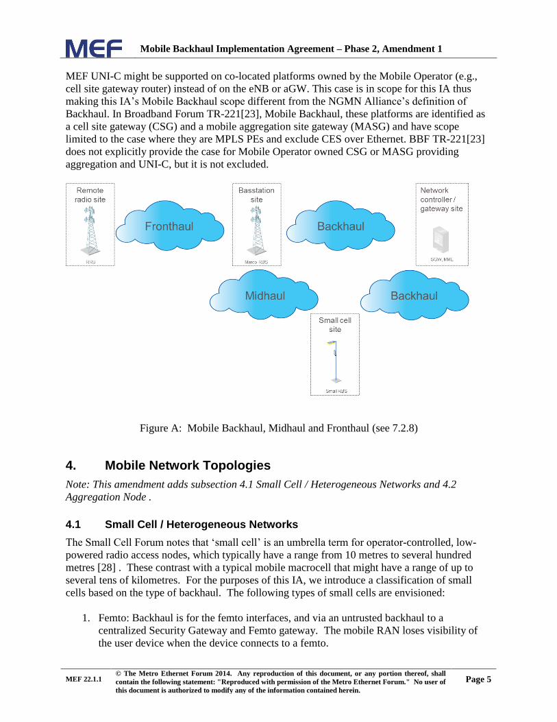
This Implementation Agreement uses the term Mobile Backhaul to refer to the network between
the Base Station sites and the Network Controller/Gateway sites for all generation of Mobile
Technologies. Additionally, this IA introduces a variant of Mobile Backhaul termed Midhaul
that refers to the network between basestation sites (especially when one site is a small cell site).
It is useful to also use the term Fronthaul to refer to the intra-basestation transport -- that is
between the baseband unit and radio unit. These terms are shown in Figure A. The NGMN
Alliance [28] defines Backhaul Solution for LTE and Wimax as including the transport module
in the base station (e.g. eNB in LTE or Base Station in Wimax) to the transport module in the
controller (aGW). When the transport modules in the eNB or aGW also support MEF’s UNI-C
functions then the NGMN Alliance’s definition of Backhaul is equivalent in scope to MEF’s
UNI-C to UNI-C Subscriber EC (MEF 12.1[7]) and this IA’s Mobile Backhaul. In some cases,
Mobile Backhaul Implementation Agreement – Phase 2, Amendment 1
MEF 22.1.1 © The Metro Ethernet Forum 2014. Any reproduction of this document, or any portion thereof, shall
contain the following statement: "Reproduced with permission of the Metro Ethernet Forum." No user of
this document is authorized to modify any of the information contained herein.
Page 5
MEF UNI-C might be supported on co-located platforms owned by the Mobile Operator (e.g.,
cell site gateway router) instead of on the eNB or aGW. This case is in scope for this IA thus
making this IA’s Mobile Backhaul scope different from the NGMN Alliance’s definition of
Backhaul. In Broadband Forum TR-221[23], Mobile Backhaul, these platforms are identified as
a cell site gateway (CSG) and a mobile aggregation site gateway (MASG) and have scope
limited to the case where they are MPLS PEs and exclude CES over Ethernet. BBF TR-221[23]
does not explicitly provide the case for Mobile Operator owned CSG or MASG providing
aggregation and UNI-C, but it is not excluded.
Figure A: Mobile Backhaul, Midhaul and Fronthaul (see 7.2.8)
4. Mobile Network Topologies
Note: This amendment adds subsection 4.1 Small Cell / Heterogeneous Networks and 4.2
Aggregation Node .
4.1 Small Cell / Heterogeneous Networks
The Small Cell Forum notes that ‘small cell’ is an umbrella term for operator-controlled, low-
powered radio access nodes, which typically have a range from 10 metres to several hundred
metres [28] . These contrast with a typical mobile macrocell that might have a range of up to
several tens of kilometres. For the purposes of this IA, we introduce a classification of small
cells based on the type of backhaul. The following types of small cells are envisioned:
1. Femto: Backhaul is for the femto interfaces, and via an untrusted backhaul to a
centralized Security Gateway and Femto gateway. The mobile RAN loses visibility of
the user device when the device connects to a femto.

Mobile Backhaul Implementation Agreement – Phase 2, Amendment 1
MEF 22.1.1 © The Metro Ethernet Forum 2014. Any reproduction of this document, or any portion thereof, shall
contain the following statement: "Reproduced with permission of the Metro Ethernet Forum." No user of
this document is authorized to modify any of the information contained herein.
Page 6
2. Pico/Micro: This is an eNB or NB that is exactly the same as a macro eNB/NB only
smaller in size and power. It uses Iub, S1, X2 interfaces on the backhaul and is visible to
the macro layer.
MEF services, and this IA, are focused on “pico/micro” small cells. While not prohibited, MEF
services used for “femto” small cells are outside the scope of this IA. Note that the base
stations described previously in Figure 1 (BTS, nodeB), Figure 2 (eNB) and Figure 3 (BS) may
be “pico/micro” small cells.
‘Heterogeneous’ refers to the different types of base stations (e.g., macro, micro, pico) that are
used together in the same wireless network to build the coverage and capacity that end-users
demand from their operator. This is in contrast to ‘homogeneous’ networks that are built with
one type of base station, often the macro. As a result, a heterogeneous network (HetNet)
provides a seamless broadband user experience for mobile customers independent from their
location. Note that the small cells (e.g., micro, pico) can include additional radio access
technologies, such as WLAN, which share the small cell backhaul.
As can be seen with the lower (purple dotted) line in Figure B, the available capacity for a
subscriber depends on their location. There are three improvements (identified in the in Figure
B) that HetNet could address for operators:
1. To increase the capacity on existing cells and for the network as a whole.
2. To improve performance in the cell edges.
3. To provide coverage or to improve performance indoors.
Figure B: Increase capacity & coverage for better mobile end user experience

Mobile Backhaul Implementation Agreement – Phase 2, Amendment 1
MEF 22.1.1 © The Metro Ethernet Forum 2014. Any reproduction of this document, or any portion thereof, shall
contain the following statement: "Reproduced with permission of the Metro Ethernet Forum." No user of
this document is authorized to modify any of the information contained herein.
Page 7
Figure B, Solution 1 (indicated by 1 in the figure), Macro Optimization:
Usually, the most effective first step in improving overall performance in a mobile network is to
optimize existing macro sites by updating technology, aligning antennas, adding frequencies and
sectors, etc.
Figure B, Solution 2, Cell Split:
Should Solution 1 not be sufficient, the common next step is to add additional macro sites that
are similar to existing macro sites. A cell split typically dramatically increases capacity in the
cell edge and results in more consistent network coverage with better performance.
Figure B, Solution 3, Small Cells Additions:
Additionally, the operator can choose to deploy small cells to solve coverage holes or to increase
capacity in some regions. In fact, these coverage and capacity issues might exist even if the
operator implemented Solutions 1 and 2. There can be several micro and pico small cells
required within a macro cell coverage area with each offloading a small percentage of the macro
capacity. Other areas that can benefit from the addition of these “small cells” will again be cell
edges where speed and throughput benefit from a well placed small cell. Example use cases
support indoor areas such as homes or businesses to provide better coverage and/or increase
capacity.
4.1.1 Radio Coordination
Radio coordination is a concept that is very important with respect to HetNet. To clarify,
consider the extremes. If one is using separate frequencies for small cells and the macro cell,
there is no need for coordinating the radio resources. Similarly, coordination is not needed when
an indoor cell is shielded from the external macro cells using the same frequencies and radio
resources.
The other extreme is when the same frequencies are used and interference impedes performance.
In this case, some form of tight radio coordination is required to optimize performance. In this
scenario, the macro cell and the small cells are communicating with each other and coordinating
simultaneous use of resources. For example, a terminal can use the downlink from a macro cell
and the uplink from a small cell with resource utilization coordinated between the cells. This
helps to mitigate the performance issues associated with interference, but it places very stringent
requirements on delay, synchronization and in some cases, bandwidth.
The need for coordination varies significantly. The “very tight coordination” case is the most
extreme in terms of requirements and performance. The backhaul/midhaul can support a lesser
degree of coordination to enhance the performance and total bandwidth in an area by way of
incremental differences in the radio technology (e.g., certain LTE or LTE-A features)and
associated requirements on the backhaul transport characteristics. MEF Ethernet service
solutions with relatively stringent performance, including low latency and sufficient bandwidth,
meet these “tight coordination” requirements in some cases. With the use of GNSS/GPS or the
addition of more accurate network-delivered synchronization solutions (e.g., packet-based
method with full timing support to the protocol level from the network [15], also known as PTP
with “on-path”support) to deliver improved time alignment between cells, it might be possible to
Mobile Backhaul Implementation Agreement – Phase 2, Amendment 1
MEF 22.1.1 © The Metro Ethernet Forum 2014. Any reproduction of this document, or any portion thereof, shall
contain the following statement: "Reproduced with permission of the Metro Ethernet Forum." No user of
this document is authorized to modify any of the information contained herein.
Page 8
use more demanding radio coordination features. Additional Synchronization requirements for
phase and time synchronization associated with these radio technologies that provide for
coordination are described in Appendix D.
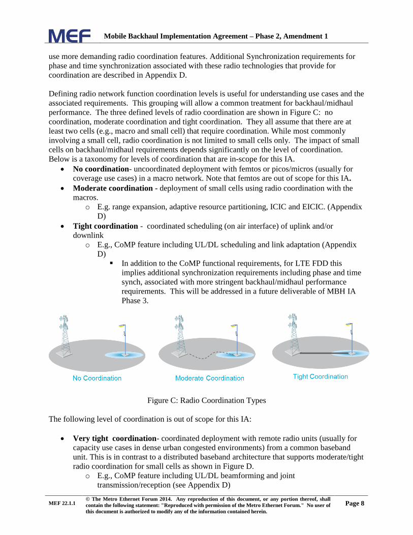
Defining radio network function coordination levels is useful for understanding use cases and the
associated requirements. This grouping will allow a common treatment for backhaul/midhaul
performance. The three defined levels of radio coordination are shown in Figure C: no
coordination, moderate coordination and tight coordination. They all assume that there are at
least two cells (e.g., macro and small cell) that require coordination. While most commonly
involving a small cell, radio coordination is not limited to small cells only. The impact of small
cells on backhaul/midhaul requirements depends significantly on the level of coordination.
Below is a taxonomy for levels of coordination that are in-scope for this IA.
No coordination- uncoordinated deployment with femtos or picos/micros (usually for
coverage use cases) in a macro network. Note that femtos are out of scope for this IA.
Moderate coordination - deployment of small cells using radio coordination with the
macros.
o E.g. range expansion, adaptive resource partitioning, ICIC and EICIC. (Appendix
D)
Tight coordination - coordinated scheduling (on air interface) of uplink and/or
downlink
o E.g., CoMP feature including UL/DL scheduling and link adaptation (Appendix
D)
In addition to the CoMP functional requirements, for LTE FDD this
implies additional synchronization requirements including phase and time
synch, associated with more stringent backhaul/midhaul performance
requirements. This will be addressed in a future deliverable of MBH IA
Phase 3.
Figure C: Radio Coordination Types
The following level of coordination is out of scope for this IA:
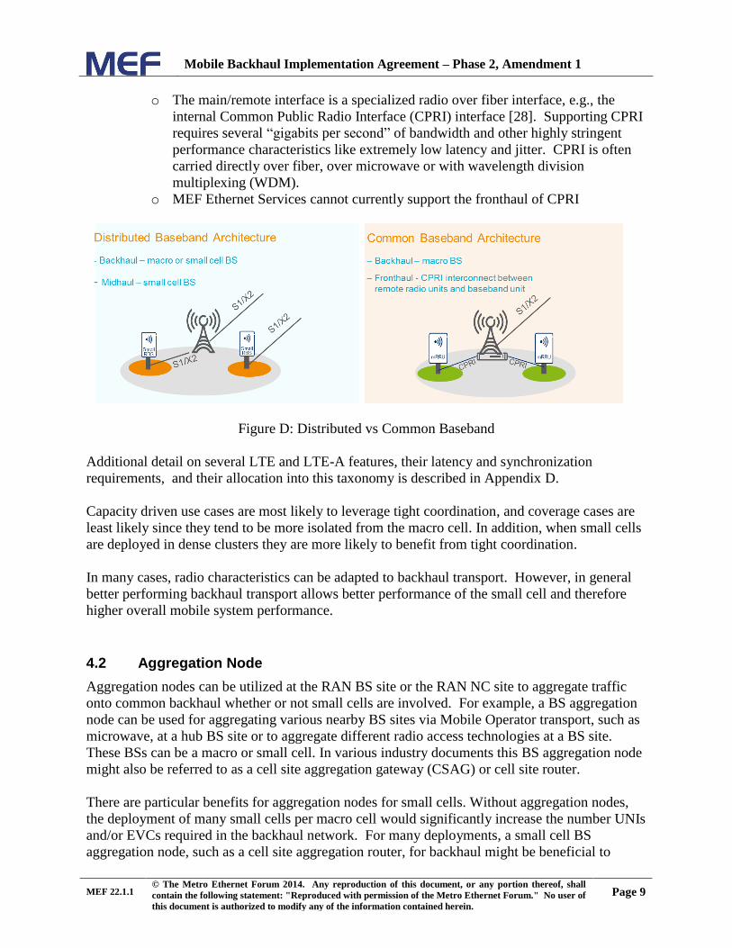
Very tight coordination- coordinated deployment with remote radio units (usually for
capacity use cases in dense urban congested environments) from a common baseband
unit. This is in contrast to a distributed baseband architecture that supports moderate/tight
radio coordination for small cells as shown in Figure D.
o E.g., CoMP feature including UL/DL beamforming and joint
transmission/reception (see Appendix D)
Mobile Backhaul Implementation Agreement – Phase 2, Amendment 1
MEF 22.1.1 © The Metro Ethernet Forum 2014. Any reproduction of this document, or any portion thereof, shall
contain the following statement: "Reproduced with permission of the Metro Ethernet Forum." No user of
this document is authorized to modify any of the information contained herein.
Page 9
o The main/remote interface is a specialized radio over fiber interface, e.g., the
internal Common Public Radio Interface (CPRI) interface [28]. Supporting CPRI
requires several “gigabits per second” of bandwidth and other highly stringent
performance characteristics like extremely low latency and jitter. CPRI is often
carried directly over fiber, over microwave or with wavelength division
multiplexing (WDM).
o MEF Ethernet Services cannot currently support the fronthaul of CPRI
Figure D: Distributed vs Common Baseband
Additional detail on several LTE and LTE-A features, their latency and synchronization
requirements, and their allocation into this taxonomy is described in Appendix D.
Capacity driven use cases are most likely to leverage tight coordination, and coverage cases are
least likely since they tend to be more isolated from the macro cell. In addition, when small cells
are deployed in dense clusters they are more likely to benefit from tight coordination.
In many cases, radio characteristics can be adapted to backhaul transport. However, in general
better performing backhaul transport allows better performance of the small cell and therefore
higher overall mobile system performance.
4.2 Aggregation Node
Aggregation nodes can be utilized at the RAN BS site or the RAN NC site to aggregate traffic
onto common backhaul whether or not small cells are involved. For example, a BS aggregation
node can be used for aggregating various nearby BS sites via Mobile Operator transport, such as
microwave, at a hub BS site or to aggregate different radio access technologies at a BS site.
These BSs can be a macro or small cell. In various industry documents this BS aggregation node
might also be referred to as a cell site aggregation gateway (CSAG) or cell site router.
There are particular benefits for aggregation nodes for small cells. Without aggregation nodes,
the deployment of many small cells per macro cell would significantly increase the number UNIs
and/or EVCs required in the backhaul network. For many deployments, a small cell BS
aggregation node, such as a cell site aggregation router, for backhaul might be beneficial to

Mobile Backhaul Implementation Agreement – Phase 2, Amendment 1
MEF 22.1.1 © The Metro Ethernet Forum 2014. Any reproduction of this document, or any portion thereof, shall
contain the following statement: "Reproduced with permission of the Metro Ethernet Forum." No user of
this document is authorized to modify any of the information contained herein.
Page 10
aggregate the BSs onto a single MBH interface. A typical use for such an aggregation node
would be in a building with a number of small cell BSs as shown in Figure E. While this
aggregation node is not an eNB/NB, it can be considered a RAN BS in the context of this IA,
requiring a single backhaul. This is similar to the case in macro cell site backhaul whereby a BS
aggregation node is used to aggregate multiple macro base stations and/or multiple radio
technologies onto a single backhaul UNI.
Figure E: Small Cell BS aggregation node
BS aggregation nodes are a type of RAN CE. They are normally owned by the Mobile Operator
and thus considered CE from a MEF perspective. BS aggregation nodes will not be normatively
specified in this IA (See appendix A.1). BS aggregation nodes can implement generic MEF
functionality that is attributed to CE and UNI-C functions in various MEF specifications. A
generic view is shown in Figure F that encompasses a multi-operator aggregation, multi-
standard radio aggregation and small cell aggregation. There are many variations that are
possible for deployment. The common element in all deployments is the CSAG function.

Mobile Backhaul Implementation Agreement – Phase 2, Amendment 1
MEF 22.1.1 © The Metro Ethernet Forum 2014. Any reproduction of this document, or any portion thereof, shall
contain the following statement: "Reproduced with permission of the Metro Ethernet Forum." No user of
this document is authorized to modify any of the information contained herein.
Page 11
Figure F: Generalized BS aggregation node
5. Scope
Note: This amendment replaces section 5 with the following
5.1 In Scope
The following are within the scope of this phase of Implementation Agreement:
Mobile backhaul and midhaul, for macro and small cells, for mobile technologies referenced
in standards: GSM, WCDMA, CDMA2000, WiMAX 802.16e, and LTE.
Support a single MEN with External Interfaces being only UNIs for Mobile Backhaul
between RAN BSs and RAN NC.
Utilize existing MEF technical specifications with required extensions to interface and
service attributes.
Provide requirements for UNI-C and UNI-N beyond those in [8] and [10].
Define requirements for Mobile Backhaul with Ethernet Services specified in MEF 6.1 [3].
Provide requirements for Link OAM, Service OAM Fault Management.

Mobile Backhaul Implementation Agreement – Phase 2, Amendment 1
MEF 22.1.1 © The Metro Ethernet Forum 2014. Any reproduction of this document, or any portion thereof, shall
contain the following statement: "Reproduced with permission of the Metro Ethernet Forum." No user of
this document is authorized to modify any of the information contained herein.
Page 12
Provide requirements for CoS and recommend performance objectives consistent with MEF
23.1 [12], where possible.
Specify frequency synchronization requirements where possible for packet based
synchronization methods and Synchronous Ethernet.
Define functional requirements applicable to Generic Inter-Working Function interfaces.
Specify resiliency related performance requirements for Mobile Backhaul.
5.2 Out of Scope
Topics that are not within the scope of this phase of Implementation Agreement include:
Consider Multiple MENs or External Interfaces such as ENNI
Provide an architectural and functional description of the MEN internals.
Provide a normative definition or implementation specification of the Generic Inter-working
Function.
Provide details regarding other technologies for Backhaul Networks (e.g. Legacy ATM or TDM or IP transport).
Specify time and phase synchronization methods and requirements.
Specify multiple clock & time domain synchronization methods and requirements.
Define synchronization architectures or promote any particular synchronization technology.
Define mobile network evolution scenarios.
Provide fronthaul between a baseband unit and a radio unit (e.g., “very tight
coordination” case using CPRI)
Specify backhaul for femto interfaces
6. Compliance Levels
The key words "MUST", "MUST NOT", "REQUIRED", "SHALL", "SHALL NOT",
"SHOULD", "SHOULD NOT", "RECOMMENDED", "MAY", and "OPTIONAL" in this
document are to be interpreted as described in IETF RFC 2119[25]. All key words must be in
upper case, bold text.
Items that are REQUIRED (contain the words MUST or MUSTNOT) will be labeled as [Rx]
for required. Items that are RECOMMENDED (contain the words SHOULD or
SHOULDNOT) will be labeled as [Dx] for desirable. Items that are OPTIONAL (contain the
words MAY or OPTIONAL) will be labeled as [Ox] for optional.
A paragraph preceded by [CRa]< specifies a conditional mandatory requirement that MUST be
followed if the condition(s) following the “<” have been met. For example, “[CR1]<[D38]”
indicates that Conditional Mandatory Requirement 1 must be followed if Desirable Requirement
38 has been met. A paragraph preceded by [CDb]< specifies a Conditional Desirable
Requirement that SHOULD be followed if the condition(s) following the “<” have been met. A
paragraph preceded by [COc]< specifies an Conditional Optional Requirement that MAY be
followed if the condition(s) following the “<” have been met.

Mobile Backhaul Implementation Agreement – Phase 2, Amendment 1
MEF 22.1.1 © The Metro Ethernet Forum 2014. Any reproduction of this document, or any portion thereof, shall
contain the following statement: "Reproduced with permission of the Metro Ethernet Forum." No user of
this document is authorized to modify any of the information contained herein.
Page 13
7. Mobile Backhaul Service Model
Note: This amendment modifies Subsection 7.1.2 and adds Subsections 7.2.7 and 7.2.8 at the
end of this section.
7.1.2 Use Case Variations
Note: Add a new paragraph to the end of this section.
The RAN CE basestation shown in Figures 7, 8 and 9 represents both small cells and macro
cells. That is, for this use case either could be present.
7.2.7 Use Case Variations for small cells
This section describes and provides examples of variations to use cases 1 and 2 for different
Small Cells, including mixed CEN and IP MBH.
In all cases, the RAN BS can be relatively larger (e.g., macro cell) or smaller (e.g., small cells
such as micro, pico, femto). While use cases 1 and 2 can be applied to macro as well as small
cell BS, use case 2b will be a common use case for small cells since small cells are relatively
new and do not usually include TDM interfaces.
The addition of small cells will require an increase in backhaul capacity to the macro site
(especially if small cells are aggregated there – see Appendix A.1) or providing new
backhaul/midhaul to the additional small cell BS sites. The performance requirements on the
backhaul/midhaul will be the same as macro only sites except in cases where the small cell radio
technology requirements have been relaxed (e.g., less demanding requirements for peak rate
demand, handover or service continuity) or in the case where some of the tight radio
coordination features are to be used. In this tight coordination case, the performance
requirements (e.g., latency, CIR/EIR and/or synchronization) might be more demanding. See
section 4.1.1 for details on radio coordination.

Mobile Backhaul Implementation Agreement – Phase 2, Amendment 1
MEF 22.1.1 © The Metro Ethernet Forum 2014. Any reproduction of this document, or any portion thereof, shall
contain the following statement: "Reproduced with permission of the Metro Ethernet Forum." No user of
this document is authorized to modify any of the information contained herein.
Page 14
Figure G: Use case examples with CEN and non-CEN hybrid
The use case examples in Figure G shows the MEF service closest to the basestation as an
extension of another non-MEF service – there may or may not be another MEF service at the
RAN NC site. BBF TR-221 explains this case in more detail for the cases when the non-MEF
services are MPLS. Note that this could also be deployed in the reverse case with Non-MEF
closest to the basestation. The latter is expected to be prevalent in small cell deployments.
7.2.8 Use Case 3: RAN CE with Macro Backhaul Extensions to Small Cells
Use case 3 in Figure H illustrates a deployment option where extensions are made to existing
backhaul connections to the macro site. In this case, the RAN CE equipment can be connected
directly to the CEN with a MEF compliant UNI-C Ethernet, but there are two separate EVCs.
The existing EVC(m) is shown on the right and a new EVC(sc) is shown on the left connecting
the RAN CE of the macro site with the RAN CE of the small cell. Both EVCs use MEF 6.1
services and appear as entirely separate services to each CEN which may be from different CEN
Operators.

Mobile Backhaul Implementation Agreement – Phase 2, Amendment 1
MEF 22.1.1 © The Metro Ethernet Forum 2014. Any reproduction of this document, or any portion thereof, shall
contain the following statement: "Reproduced with permission of the Metro Ethernet Forum." No user of
this document is authorized to modify any of the information contained herein.
Page 15
Figure H: Use Case 3: small cell extension from macro
HetNet EVC(sc) midhaul can have different requirements than EVC(m) backhaul. There are a
number of options for the functions that could occur at the middle Mobile Network RAN BS site
that will not be normatively specified in this IA, though several options are possible. For
example, an aggregation router or a Ethernet switching device could be present which would
present different relationships between single or multiple EVC(sc) with EVC (m) and might
present options for implementing direct RAN BS to RAN BS traffic such as X2 for LTE (or the
evolving X2+ for LTE small cells). The router or switching device would allow concentration of
multiple small and macro cells onto EVC(m) for implementing traffic to the NC like S1 for LTE.
The small cell RAN BS, like the macro cell RAN BS, may or may not be the device at the site
with the UNI-C. If it is not, another device (router, switch or NID) would contain the UNI-C.
If separate frequencies are used for macro and small cells or if interference risk is low, there
might not be significant difference other than capacity. However, if there is a risk of
interference, the EVC(sc) midhaul might have different requirements, not only on capacity, but
on delay and delay variation, to maximize the utilization of the radio resources using a tighter
level of radio coordination. The constrained requirements on the backhaul/midhaul will thus be
dependent on the level of radio coordination. This is addressed in section 11.5.2. However, it is
important to note that this small cell extension use case can realize several different RAN
interconnection topologies for the LTE small cell. As shown in the Figures below, these are:
1. S1 only (Figure I)
The midhaul EVC for the LTE small cell carries only LTE S1 traffic. This is transited at
the macro basestation site and is transported with the macro LTE S1 traffic over the
backhaul EVC. The constraints are the same as for backhaul (e.g., PT1 per 11.5.2).
2. S1 and X2 (Figure J)
The midhaul EVC for the LTE small cell carries LTE S1 and X2 traffic. The S1 traffic is
transisted as above, but the X2 traffic is only between cell sites. Radio coordination is
supported and tight radio coordination will add constraints to the midhaul (e.g.,
constrained PT1 per 11.5.3)
3. Xn (Figure K)
The midhaul EVC for the LTE small cell carries only LTE Xn traffic. This evolving
3GPP Release 12 feature [22] involves a split bearer such that the small cell is directly
connected to its master basestation. The constraints on this type of midhaul are the same
as backhaul (e.g., PT1 or PT2 per 11.5.4).

Mobile Backhaul Implementation Agreement – Phase 2, Amendment 1
MEF 22.1.1 © The Metro Ethernet Forum 2014. Any reproduction of this document, or any portion thereof, shall
contain the following statement: "Reproduced with permission of the Metro Ethernet Forum." No user of
this document is authorized to modify any of the information contained herein.
Page 16
Figure I: Use case 3a: Small cell extension for LTE S1 only
Figure J: Use case 3b: Small cell extension for LTE S1 and X2 (radio coordination possible)
only
Figure K: Use case 3c: Small cell extension for LTE Xn only
It should be noted that unless they are mapped unto different EVCs, the LTE interfaces (S1, X2,
Xn) will not be distinguishable to the CEN. The use cases highlight the varying CoS

Mobile Backhaul Implementation Agreement – Phase 2, Amendment 1
MEF 22.1.1 © The Metro Ethernet Forum 2014. Any reproduction of this document, or any portion thereof, shall
contain the following statement: "Reproduced with permission of the Metro Ethernet Forum." No user of
this document is authorized to modify any of the information contained herein.
Page 17
requirements. In some cases, the Mobile Operator is likely to provide the midhaul EVC(sc)
themselves - depending on service availability – however, modeling the interconnection as an
MEF service would still be useful (e.g., for planning or certification). These relatively short
mobile backhaul needs would generally be prior to the CEN Operator’s first office or switching
location and therefore dedicated transport is likely to be most common. Example cases include
the Mobile Operator utilizing microwave Ethernet transport to provide this short midhaul, or the
Mobile Operator acquiring wireline physical assets like dark fiber. Topologies that involve the
transport of the frames to a central office switch and back to the Macro RAN BS site might not
be cost or performance suitable.
11. EVC Requirements
Note: This amendment adds subsection 11.5.3 and 11.5.4
11.5.3 CoS Performance Objectives (CPOs) for Small Cells With Tight Radio Coordination
In 3G and 4G Mobile Networks the midhaul transport for small cell use case 3 (section 7.2.8)
will be between the macro RAN BS and the small cell RAN BS within a relatively small distance
(e.g. resulting in EVCs of <10km). Across this midhaul interface there can be logical interfaces
between the RAN BS sites (e.g., X2 for LTE) and/or it might contain a portion of logical
interfaces for the RAN NC (e.g., S1) (per use cases 3a and 3b).
A macro-based mobile broadband network optimized for maximum performance, in capacity and
coverage, will be complemented with small cells that for maximum performance may need to be
tightly coordinated with the macro cells and potentially with other small cells. For maximum
performance of radio features there are additional constraints that can be placed on the midhaul
transport between the macro RAN BS and the small cell RAN BS. In such a case, assuming
MEF services are used, those services may need to provide additionally constrained CoS
performance objectives (CPOs) for small cells as shown in Figure L:
Figure L: Two CPOs for Use Case 3

Mobile Backhaul Implementation Agreement – Phase 2, Amendment 1
MEF 22.1.1 © The Metro Ethernet Forum 2014. Any reproduction of this document, or any portion thereof, shall
contain the following statement: "Reproduced with permission of the Metro Ethernet Forum." No user of
this document is authorized to modify any of the information contained herein.
Page 18
This IA recommends use of CPOs that are generally more stringent than the most stringent
Performance Tier currently specified by MEF (PT1). These “tight-coordination” CPOs are used
when tight radio coordination is implemented between the small cell and its neighboring cells,
such as when certain LTE-Advanced features including Coordinated Multi-point (CoMP) are
used.
[D1] A MEF compliant Mobile Backhaul with EVC(sc) for X2 or R8 that supports HetNet
tight radio coordination SHOULD use the CPOs in Table B which are compliant with but
more stringent than PT1 as defined in MEF 23.1 [12].
[O1] A MEF compliant Mobile Backhaul with EVC(sc) for X2 or R8 that supports HetNet
moderate or no radio coordination service MAY use PT1 or PT2 [12].
For example, a small cell backhaul/midhaul use case with relaxed radio requirements and no
radio coordination may use PT2 CoS Performance Objectives.
The existing requirements for macro backhaul will continue to apply for EVC (m). See {11.5.x].
Table B in this IA specifies the one way CPOs for Point-to-Point Mobile Backhaul service with 1
or more CoS Labels: H, M, L. This is based on tight radio coordination requirements for small
cells for Mobile Backhaul across all mobile technologies (2G to 4G) and thus will support any of
the service combinations (e.g. MEF 3, MEF 6.1) across the same CEN. It should be noted that
mapping of radio coordination “signaling” to CoS labels is shown in Table 7.
CoS
Name
Ingress
Bandwidth
Profile**
One Way CPO for Mobile Backhaul Service with Tight Radio Coordination –
constrained PT1 {S, CoS ID, PT}
FD MFD IFDV FDR FLR Availability L B
High (H)
CIR>0
EIR0 ≤1
ms
≤0.7
ms
≤0.3
ms
≤0.5 ms
See MEF 23.1
Table 6 PT1 [12]
TBD
≥AAvail TBD
≤AHLI
TBD ≤ACHLI
Medium (M)
CIR>0
EIR0 ≤ 2.9ms
≤2 ms
≤0.9ms or
N/S
≤1 ms or
N/S
See MEF 23.1
Table 6 PT1 [12]
TBD
≥AAvail TBD
≤AHLI
TBD ≤ACHLI
Low (L)
CIR≥0
EIR0* ≤10
ms
≤8 ms
≤2.8ms or
N/S
≤2.9 ms or
N/S
See MEF 23.1
Table 6 PT1 [12]
TBD
≥AAvail TBD
≤AHLI
TBD ≤ACHLI
Notes: H+ is not further constrained by this Amendment, so is not shown. Impact of feature driven Time and
Phase Synchronization is out of scope for this Amendment and is not included. In addition, no additional
constraints are required for frequency synchronization.
More stringent PT1 CPOs shown above may be utilized on a per CoS Name basis, e.g., radio default
bearer on CoS Label L may not use tight radio coordination and thus may utilize PT1 CPOs rather than
those shown for L above.
(*) both CIR = 0 and EIR = 0 is not allowed as this results in no conformant Service Frames. CIR=0
and EIR>0 results in non-specified objectives.
(**) Ingress Bandwidth Profile for CoS Labels (H, M and L) are from Table 2 of MEF 23.1[12] .
CBS, EBS MTU per MEF 23.1[12]

Mobile Backhaul Implementation Agreement – Phase 2, Amendment 1
MEF 22.1.1 © The Metro Ethernet Forum 2014. Any reproduction of this document, or any portion thereof, shall
contain the following statement: "Reproduced with permission of the Metro Ethernet Forum." No user of
this document is authorized to modify any of the information contained herein.
Page 19
Table B: One way CPOs for “tight radio coordination” for Point-to-Point Mobile Backhaul case
when Synchronization is not provided on the Backhaul1
CPOs for “tight radio coordination” for Point-to-Point Mobile Backhaul case when time/phase
synchronization is provided on the Backhaul are for a future deliverable in MBH Phase 3.
3GPP TR23.203 [21] suggests that the typical average delay2 for S1u traffic is 20ms. The
constrained PT1 for small cells in the figure above allow for S1 traffic carried in a multi-CoS
environment to be within reach of this average, and certainly within the 10ms to 50ms range.
Figure M below shows the component contribution to the end-to-end latency as contributed to
by node delays (assumed to be 1ms) and the constrained PT1 value of FD for EVC(sc) with CoS
Name M (5ms) and the PT1 value of FD for EVC(m) with CoS Name M (20ms). This
concatenation is shown as guidance so that operators can appropriately provision their backhaul
networks. This figure does not imply any restriction on CoS levels on the EVC(sc) and EVC(m)
segments (e.g., it could be CoS M in EVC(sc) and at CoS H at EVC(m)) to meet the 3GPP
typical average delay.
Figure M: S1u FD budget for small cell use case
11.5.4 CoS Performance Objectives (CPOs) for Small Cells With Split Bearer
3GPP TS 36.842 [22] introduces bearer splitting for LTE in support of dual connectivity. There
are 3 main options described, but recommended option 3C highlights the midhaul architecture
shown in Figure K. The small cell becomes a secondary eNB (SeNB) and is only connected to
its master eNB (MeNB). This interconnection is an X2 interface (labeled Xn) carrying both user
and control plane traffic, while supporting a slightly higher latency (see Appendix D). The
1 MEF 23.1 is being updated with the CoS Phase 3 project. This project will add a PT0.5 that is similar or
equivalent to the constrained PT1 defined here. A future revision of MEF 22 will align with MEF 23. 2 The average delay of 20 ms is between a PCEF and a radio base station. It is the delay attributed to backhaul and
should be subtracted from a given Packet Delay Budget (PDB) to derive the actual PDB that applies to the radio
interface The PDB defines an upper bound for the time that a packet may be delayed between the UE and the PCEF.
The PDB shall be interpreted as a maximum delay with a confidence level of 98 percent.

Mobile Backhaul Implementation Agreement – Phase 2, Amendment 1
MEF 22.1.1 © The Metro Ethernet Forum 2014. Any reproduction of this document, or any portion thereof, shall
contain the following statement: "Reproduced with permission of the Metro Ethernet Forum." No user of
this document is authorized to modify any of the information contained herein.
Page 20
midhaul transport required for small cell use case 3c (section 7.1.4) will be between the macro
RAN BS and the small cell RAN BS within a relatively small distance (e.g. resulting in EVCs of
<10km). However, this midhaul interface will only support the Xn logical interfaces between the
RAN BS sites
In such a case, assuming MEF services are used, those services need less constrained CoS
performance objectives (CPOs) for small cells. That is, the CPO requirements in 11.5.2 would
apply.
12. Synchronization
Note: Phase and time synchronization, for example in support of radio coordination, will be in
a future deliverable of MBH IA Phase 3
13. References
MEF Specifications
[1] MEF 3, “Circuit Emulation Service Definitions, Framework and Requirements in Metro
Ethernet Networks”
[2] MEF 4, “Metro Ethernet Network Architecture Framework Part 1: Generic Framework”
[3] MEF 6.1, “Ethernet Services Definitions - Phase 2”
[4] MEF 10.2, “Ethernet Services Attributes - Phase 2”
[5] MEF 10.2.1, Amendment to MEF 10.2
[6] MEF 11, “User Network Interface (UNI) Requirements and Framework”
[7] MEF 12.1, “Metro Ethernet Network Architecture Framework Part 2: Ethernet Services
Layer”
[8] MEF 13, “User Network Interface (UNI) Type 1 Implementation Agreement”
[9] MEF 17, “Service OAM Requirements & Framework”
[10] MEF 20, “User Network Interface (UNI) Type 2 Implementation Agreement”
[11] MEF 22.1, “Mobile Backhaul Phase 2 Implementation Agreement”
[12] MEF 23.1, “Class of Service Phase 2 Implementation Agreement”
IEEE Standards
[13] IEEE 802.1Q-2011, “Virtual Bridged Local Area Networks”
[14] IEEE 1588-2008, “Standard for A Precision Clock Synchronization Protocol for Network
Measurement and Control Systems”
ITU-T Recommendations
[15] ITU-T G.8260, “Definitions and terminology for synchronization in packet networks”,
August 2010
[16] ITU-T G.705, “Characteristics of plesiochronous digital hierarchy (PDH) equipment
functional blocks”, October 2005

Mobile Backhaul Implementation Agreement – Phase 2, Amendment 1
MEF 22.1.1 © The Metro Ethernet Forum 2014. Any reproduction of this document, or any portion thereof, shall
contain the following statement: "Reproduced with permission of the Metro Ethernet Forum." No user of
this document is authorized to modify any of the information contained herein.
Page 21
GSM, CDMA, WCDMA & LTE
[17] GSM 01.04 v8, “Abbreviations and Acronyms”, May 2000
[18] TIA IS-2000.1-A, “Physical Layer Standard for cdma2000 Spread Spectrum Systems”,
March 2000
[19] 3GPP TS 21.905V12.0.0 (2013-06), “Vocabulary for 3GPP Specifications”
[20] 3GPP TS 36.300V12.1.0 (2014-03),“Evolved Universal Terrestrial Radio Access (E-
UTRA) and Evolved Universal Terrestrial Radio Access Network (E-UTRAN); Overall
description; Stage 2”
[21] 3GPP TS 23.203V12.1.0 (2014-03), “Technical Specification Group Services and System
Aspects;Policy and charging control architecture”
[22] 3GPP TR 36.842 V12.0.0 (2013-12), “Technical Specification Group Radio Access
Networks; Study on Small cell enhancements for E-UTRA and E-UTRAN”
BBF
[23] TR-221 , "Technical Specifications for MPLS in Mobile Backhaul Networks" (October
2011)
IETF
[24] RFC 791, “Internet Protocol”
[25] RFC 2119, “Key words for use in RFCs to Indicate Requirement Levels”
[26] RFC 2460, “Internet Protocol, Version 6 (IPv6) Specification”
Wimax Forum Specifications
[27] WMF-T32-001-R016v01,“WiMAX Forum Network Architecture - Architecture Tenets,
Reference Model and Reference Points Base SpecificationStage 2. 2010-11-30”
NGMN Alliance
[28] NGMN Alliance, “NGMN Optimized Backhaul Requirements”, August
2008(http://www.ngmn.org/uploads/media/NGMN_Optimised_Backhaul_Requirements.pdf)
Small Cell Forum
[29] Small Cell Forum 102.02.01, “Release two – Enterprise: Overview”, December 2013
CPRI
[30] CPRI, “Common Public Radio Interface (CPRI); Interface Specification V6.0”, August
2013

Mobile Backhaul Implementation Agreement – Phase 2, Amendment 1
MEF 22.1.1 © The Metro Ethernet Forum 2014. Any reproduction of this document, or any portion thereof, shall
contain the following statement: "Reproduced with permission of the Metro Ethernet Forum." No user of
this document is authorized to modify any of the information contained herein.
Page 22
Appendix A. Generic Interworking Function (Informative)
Note: This amendment adds Appendix A.1 as follows
A.1 Aggregation Node
This Appendix provides an informative definition of the Aggregation Node.
BS aggregation nodes are a type of RAN CE, however they exist on the customer side of the
UNI-C. In many cases, this aggregation node (e.g., a cell site gateway or router) is connected to
the UNI-C. It may shape traffic, assign VLANs, assign CoS labels and so forth. However, it is
not visible to the UNI-C and has no direct relation to the MEF service attributes.
Figure N: Aggregation node CE in RAN BS and/or RAN NC site
In Figure N, the RAN CE is further decomposed and described for the case when a RAN BS
and/or RAN NC include aggregation node CE functionality. At a BS the Aggregation node CE
(CSAG) can aggregate various radio and RAN technologies and/or aggregate nearby BSs into a
hub site for MBH. This can include a GIWF. The AGG function in Figure N denotes an
aggregation function which can include aggregating multiple Ethernet interfaces, GIWF
interfaces, and may include other functions such as IP. This is described in more detail by BBF
in TR-221 where the CSG performs the aggregation functions described here. At the RAN NC
site the aggregation function can similarly aggregate RAN technologies and may aggregate onto
non-MEF service backhaul (e.g., IP) to a different RAN NC or Mobile Core site. This creates a
hybrid backhaul arrangement. These aggregation nodes may perform other functions as well,
including but not limited to resiliency (e.g., selecting among diverse EVC pair), GIWF (CES)
and traffic management (e.g., CoS).The Aggregation CE can appear in variations of the previous
use cases 1 and 2. Figure N is just a generic example. Variations of any of use case 1 or 2 may
include Aggregation node CE as part of the Mobile Operator CE.

Mobile Backhaul Implementation Agreement – Phase 2, Amendment 1
MEF 22.1.1 © The Metro Ethernet Forum 2014. Any reproduction of this document, or any portion thereof, shall
contain the following statement: "Reproduced with permission of the Metro Ethernet Forum." No user of
this document is authorized to modify any of the information contained herein.
Page 23
Appendix C. Mobile Backhaul Services (Informative)
C.6 Configuration alternatives for Management plane
Note: This amendment replaces Figure 30 of Appendix C.6 (to correct an error) with the
following
UNI at
BS 1, BS 2,
BS 3
PCP 6
PCP 5 EVC 100
Figure 30: Multiple CoS IDs on the EVC reserved for Management traffic

Mobile Backhaul Implementation Agreement – Phase 2, Amendment 1
MEF 22.1.1 © The Metro Ethernet Forum 2014. Any reproduction of this document, or any portion thereof, shall
contain the following statement: "Reproduced with permission of the Metro Ethernet Forum." No user of
this document is authorized to modify any of the information contained herein.
Page 24
Appendix D. Radio Coordination (Informative)
Note: This amendment adds a new Appendix D
Standardization continues in 3GPP on LTE-Advanced features that reduce interference in the
radio domain and thus increase the uplink and/or downlink speeds for the mobile handset. Any
feature that reduces interference will improve the quality of experience for the end user.
Several of these features are worth understanding as they have additional timing or latency
requirements for backhaul or midhaul – examples of these are summarized in 3. Note support
for time synchronization over the backhaul is not supported in this amendment (though it will be
part of a future deliverable of MEF MBH Phase 3), so the values are shown for information.
Time synchronization would need to be provided by other means (e.g., GNSS).

Mobile Backhaul Implementation Agreement – Phase 2, Amendment 1
MEF 22.1.1 © The Metro Ethernet Forum 2014. Any reproduction of this document, or any portion thereof, shall
contain the following statement: "Reproduced with permission of the Metro Ethernet Forum." No user of
this document is authorized to modify any of the information contained herein.
Page 25
Notes:
3GPP Standardization is ongoing in this area, as such this table is a snapshot of the
anticipated requriements. See [21]
“None” - no other requirements than the FDD or TDD system requires, and can be
supported with MEF 22.1 1
No strict requirement, performance benefit reduces with higher latency 2
Very Tight coordination case is out of scope for this phase 3
Backhaul characteristics to be determined depending on 3GPP release 12 conclusions
3GPP Standardization is ongoing. See [22]
Table D: Time and Phase Synchronization and Delay for Radio Coordination
Coordination LTE / LTE-A feature Time synch
common
reference
accuracy
Latency
Bandwidth
Moderate Range expansion None None Low
Moderate Adaptive resource partitioning None None Low
Moderate Inter-Cell Interference
Coordination (ICIC)
None None Low
Moderate eICIC
+/- 1.5us
+/- 5 us
None Low
Moderate Dual Connectivity TBD3 5-30ms
3 TBD
3
Tight CoMP - UL Coordinated
Scheduling
+/- 5 us 1-10 ms1 Low
Tight CoMP - UL Coordinated link
adaptation
None 1-10 ms1 Low
Tight CoMP - DL Coordinated
Scheduling
+/- 5 us 1-10 ms1 Low
Tight CoMP - DL Coordinated link
adaptation
None 1-10 ms1 Low
Very Tight2 CoMP - DL Coordinated
beamforming
+/- 1.5 us < 1 ms 2.5-10
Gbps
Very Tight2 CoMP - DL non-coherent joint
transmission
+/- 5 us < 1 ms < 150 Mbps
Very Tight2 CoMP - UL Joint processing +/- 1.5 us < 1 ms 2.5-10
Gbps
Very Tight2 CoMP -UL Selection combining
+/- 5 us < 1 ms < 150 Mbps

Mobile Backhaul Implementation Agreement – Phase 2, Amendment 1
MEF 22.1.1 © The Metro Ethernet Forum 2014. Any reproduction of this document, or any portion thereof, shall
contain the following statement: "Reproduced with permission of the Metro Ethernet Forum." No user of
this document is authorized to modify any of the information contained herein.
Page 26
Several 3GPP defined coordination and interference cancellation techniques are described below,
with emphasis on the impact on the backhaul:
1. Range Expansion
2. Adaptive resource partitioning
3. ICIC
4. eICIC / FeICIC
5. CoMP Coordinated Scheduling (or Dynamic Point Selection)
6. CoMP Beamforming
7. CoMP non coherent joint transmission
8. CoMP joint processing (transmission/reception)
9. Dual connectivity
Range Expansion
With the deployment of multiple small cells within the macro coverage area, more “cell-edge” is
created. Conventionally, the LTE handset (UE) associates with a base station with best downlink
(DL) signal-to-interference-plus-noise-ratio (SINR). However, a handset with larger macro
SINR may have lower path loss to the nearby small cell base station. The result is significant UL
interference at the small cells.
Range expansion (see Figure P), which has been possible since 3GPP Release 8, can be used to
expand coverage area for the small cell. Instead of SINR, the UE association can also be
determined by minimal path loss. A handover bias is set to indicate the handover trigger
between the macro and small cell. Intelligent association achieves better spectrum efficiency and
network capacity, lower interference per bit and a spatial reuse efficiency similar to cell splitting.
Figure P: Range expansion shown with handover (HO) bias.
Adaptive resource partitioning
The basic radio resource for OFDM transmission can be described as a two-dimensional
time-frequency grid that corresponds to a set of OFDM symbols and subcarriers in the time and
frequency domains. In LTE, the basic unit for data transmission is a pair of resource blocks that
correspond to a 180kHz bandwidth during a 1ms subframe. Therefore, by aggregating
Cell range with HO bias
Cell range without HO bias

Mobile Backhaul Implementation Agreement – Phase 2, Amendment 1
MEF 22.1.1 © The Metro Ethernet Forum 2014. Any reproduction of this document, or any portion thereof, shall
contain the following statement: "Reproduced with permission of the Metro Ethernet Forum." No user of
this document is authorized to modify any of the information contained herein.
Page 27
frequency resources and by adjusting transmission parameters, such as modulation order
and channel code rate, one can flexibly support a wide range of data rates.
Resource partitioning should adapt to network loading, backhaul availability, topology, SINR
conditions at UE/base station, mobility, QoS, traffic patterns, etc. Distributed, adaptive resource
partitioning schemes are essential to manage interference and optimize throughput performance
in heterogeneous networks
The nodes in the network negotiate their resource reservation by sending messages to each other.
These resource request/grant messages can be sent over backhaul connections or OTA. The slow
adaptive resource negotiation algorithm is based on node load status and feedback from active
UEs and updates every few hundred ms. Dynamically adaptive resource negotiation algorithm is
better with bursty traffic (temporarily loaning resources between nodes) but requires OTA
signaling.
› Latency: no special requirement
Scheduling
In general, scheduling refers to the process of dividing and allocating resources between
users who have data to transfer. In LTE, dynamic scheduling (1ms) is applied both to
the uplink and downlink. Scheduling should result in a balance between perceived end-user
quality and overall system performance. Channel-dependent scheduling is used to achieve high
cell throughput. Transmissions can be carried out with higher data rates by transmitting
on time or frequency resources with relatively good channel conditions. The OFDM time-
frequency grid facilitates the selection of resources in the time and frequency domains -- LTE
supports persistent scheduling and dynamic scheduling.
ICIC - frequency domain partitioning
In some cases, the macro and small cell can use separate carriers to avoid strong interference. In
this case, carrier aggregation gives flexibility in managing the interference. Essentially, the
macro cell transmits at full power on its primary carrier frequency and lower power on the
second carrier frequency. The small cell then uses the second carrier frequency as its primary
carrier.
While this does not require time synchronization, it also offers less granular resource allocation
as partitioning is limited by the number of carriers. As a result, this does not scale beyond a few
small cells per macro cell.
› Latency: no special requirement
eICIC / FeICIC – time domain partitioning
Enhanced ICIC, is essentially time domain partitioning of resources in such a way to minimize
the interference between the macro cell and the small cell in a large range expansion (also called

Mobile Backhaul Implementation Agreement – Phase 2, Amendment 1
MEF 22.1.1 © The Metro Ethernet Forum 2014. Any reproduction of this document, or any portion thereof, shall
contain the following statement: "Reproduced with permission of the Metro Ethernet Forum." No user of
this document is authorized to modify any of the information contained herein.
Page 28
handover bias) operation. That is, when the UE is intentionally locked onto a weak DL small
cell.
With a range expansion of RE dB, a user connected to a small cell can be hit by one or more
interfering downlink signals from macro cells that are RE dB stronger than the desired signal –
plus the handover margin. With a moderate value of RE, that is, a moderate cell selection offset,
the radio interface is robust enough to handle this situation. For larger values of cell selection
offset, the macro cells can be muted or made to use reduced power. This may be done in a static
or traffic adaptive pattern. Care must be taken not to mute the macro too often, which might lead
to worse performance since the (overloaded) macro cell becomes even more
loaded during its active periods.
Figure Q: enhanced Inter Cell Interference Coordination (eICIC)
This is supported in LTE by static and adaptive Almost Blank Sub-frames (ABS) and Reduced
Power Sub-frames (RPS). To support large cell selection offsets, almost blank subframes (ABS)
were introduced in LTE release 10. One drawback of this approach is that when the data channel
in the macro base station is completely switched off, there is a degradation in performance for
users connected to the macro base station. The reduced transmission time leads directly to lower
data rates, which leads indirectly to increased load (higher resource utilization) for the same
amount of carried traffic. This effect can be mitigated by not completely switching off the macro
data channel in the ABS, but instead reducing the power to a level that the small cell users can
support. This concept is referred to as reduced power subframes (RPS). Capacity gains of up to
100 percent have been seen in 3GPP-defined scenarios
Using the LTE eICIC concept, the macro base stations schedule RPSs in a periodically repeated
pattern. The pattern is signaled to neighbor base stations to enable them to schedule users in the
imbalance zone when the macro power is reduced. The fraction of RPSs in the pattern can be
adapted to the traffic situation. This is known as adaptive RPS. RPS is preferred over ABS as it
more efficiently utilizes resources in all sub-frames.
.
eICIC consists of three design principles
1.Time domain interference management (Rel-10)
Severe interference limits the association of terminals to small cells

Mobile Backhaul Implementation Agreement – Phase 2, Amendment 1
MEF 22.1.1 © The Metro Ethernet Forum 2014. Any reproduction of this document, or any portion thereof, shall
contain the following statement: "Reproduced with permission of the Metro Ethernet Forum." No user of
this document is authorized to modify any of the information contained herein.
Page 29
2.Cell range expansion (Rel-10/11)
Time domain resource partitioning enables load balancing between macro
and small cells. Resource partitioning needs to adapt to traffic load
3. Interference cancellation receiver in the terminal (Rel-11/12)
Ensures that weak cells can be detected and interference removed.
Inter cell interference cancellation for control and data channels
The latter principle is sometimes refered to as a further enhanced ICIC (FeICIC).
› Time alignment: +/-1.5us -- +/-5us required between macro and small cell
› Latency: no special requirement (>20ms)
Coordinated Multipoint (CoMP)
Coordinated Multipoint is effectively a network MIMO utilizing multiple antenans at different
cell sites, all of which have visibility to the handset (UE).
For Downlink (DL) CoMP, this is explicitly supported from 3GPP Rel-11 amd mostly relies on
UE feedback. This results in a medium performance benefit.
Uplink (UL) CoMP currently has little 3GPP specification impact as it is mainly implementation
and inter-node communication. That is, it is similar to soft/softer handover. However, this can
result in a large performance benefit. There are several CoMP methods that have been defined in
Rel 11 and that will be further enhanced in Rel 12.
Figure R: Several options of CoMP (Coordinated Multipoint)
Coordinated Scheduling / Dynamic Point Blanking
Coordinated scheduling is a CoMP method in which a joint scheduling decision is taken across a
set of cells, rather than letting each cell's scheduler operate independently. As an example, using
coordinated scheduling a macro base station might be silent or use reduced power, only when a
nearby small cell base station schedules a user that would have been heavily interfered by the
macro base station, such as a user in the imbalance zone. Coordinated scheduling is also known
as 'dynamic point blanking' and corresponds to fully dynamic ABS/RPS.
Null forming
Dynamic Point Blanking
Coordination Coordinated Beamforming
Coordination Dynamic Point Selection
Dynamic
switching
Joint Transmission or Reception
Simultaneous
transmission or reception
different resources scheduled
Mobile Backhaul Implementation Agreement – Phase 2, Amendment 1
MEF 22.1.1 © The Metro Ethernet Forum 2014. Any reproduction of this document, or any portion thereof, shall
contain the following statement: "Reproduced with permission of the Metro Ethernet Forum." No user of
this document is authorized to modify any of the information contained herein.
Page 30
Essentially, the UE receives data from single TX point. Scheduling of time/frequency resources
is coordinated among points. This exchange of coordination information between points, is on a
per TTI (transmission time interval) level (i.e., every 1ms).
› Time alignment: +/-1.5us required between macro and small cell
› Latency: 1..10ms – the lower the latency, the better the cell edge gain
Joint Reception
CoMP joint reception is a UL CoMP method that involves precise scheduling of UE on the
uplink. The CoMP base stations receive the transmitted data from the UE. One basestation is
the master as they share received data and jointly process it. A communication between the UE
and master basestion (ACK/NACK) as well as to the other basestation is required.
› Time alignment: +/-1.5us required between macro and small cell
› Latency: <0.5ms
Dual Connectivity
Dual connectivity (3GPP Rel 12 [22]) involves a UE consuming radio resources from at least
two different base stations connected with midhaul or backhaul (both called “non-ideal
backhaul” in 3GPP). This results in a UL/DL split between the basestations that increases
throughput and decreasing HO signalling. In the case where this is deployed with an Xn
interface between the master eNB and a secondary eNB the requirements on this midhaul
connection can be relaxed and support latency of up to 30ms and have sufficient bandwidth.
› Latency: 5-30ms
________________________