Embed Size (px)
Citation preview

Meeting the Challenges of Fluid-Structure Interaction
Alan Mueller, Chief Technology Officer

Air Interaction with a Flexible Structure
What is FSI?

Water/Air Interaction with a Structure
What is FSI?

Vortex Induced Vibration and Galloping
What is FSI?
4

Aeroelastic Flutter
What is FSI?
5

Hydroplaning
What is FSI?
6

Gulping
What is FSI?
7

Ask 20 engineers “What is FSI?” and you will likely get 20 different answers There is not simply one approach valid for all FSI problems The analyst must be presented with a range of options and chose the most suitable
What is FSI?
8

Mapping data techniques – Finding neighbors and interpolating
Protocols and formats for exchanging data – Getting data from Code A to Code B
Coupling methods – Algorithms for accuracy, stability
Dynamic fluid mesh evolution – Topology changes in the fluid domain
Validation of FSI results
The Challenges of FSI
9

The Challenges of FSI
10
MAPPING

Searching for opposing neighbors Interpolating source stencil data on a target point – Source and targets may be face or vertex
Often requires integration (quadratures) – intensive extensive variables
• pressure force • heat flux heat
– FEA nodal loads: integration of intensive variables against the shape function.
The 3 steps of “Mapping”
11

Search requires little user intervention The search excludes potential neighbors based on proximity and orientation Critically important for sheet metal parts – resolve ambiguities of poor geometry – thin solid parts may be on the wrong side of the fluid surface
Parallel Mapping is a must! – Takes advantage of distributed memory
Source Neighbor Search Imperative
12

Co-Simulation Vehicle Thermal Management

Mapping Displacement in Low Y+ Prism Meshes
14
C0 continuous mapping very important for low y+ meshes
Otherwise very easy for morpher to invert high aspect ratio cells in prism layer

The Challenges of FSI
15
DATA EXCHANGE

File Based Transfer: Import/Map/Export – Data exchange via files on a hard-disk – CAE codes need not be resident in memory – Often called “Loose Coupling” – User responsible for exchange synch
Socket Based Transfer: Co-Simulation API – CAE code and STAR-CCM+ in memory – Data exchanged via sockets – API controls exchange synchronization
Methods for Exchanging Data
16

Coupling via Abaqus Co-Simulation API of SIMULIA – Manages Coupling Synchronization/Exchange/Mapping – Abaqus v6.12/STAR-CCM+ v7.04 (implicit coupling)
STAR-CCM+ Abaqus (explicit or standard) – Initial geometry – Pressure(relative or absolute pressure) – Shear traction – Surface heat flux
Abaqus STAR-CCM+ – Displacement, velocity – Temperature
Abaqus/STAR-CCM+ Co-Simulation
17

Abaqus/STAR-CCM+ Co-Simulation Interface
18
Hit the Step or Run button to commence the co-simulation

The Challenges of FSI
19
Coupling Technique

Two-way coupling for aeroelastic or hydroelastic equilibrium
One way static coupling for thermal stresses – structural temperature computed by CFD CHT
One way dynamic coupling – Loads only go from fluid to structure – Loads only go from structure to fluid
Two way dynamic coupling – explicit (exchange once per time step) – or implicit (multiple exchange per time step)
Degrees of Coupling
20

Dynamic Mesh Evolution
The Challenges of FSI
21

Completely define a good quality fluid mesh – Using as little user intervention as possible
Options within STAR-CCM+ – Rigid body motion, sliding interfaces – Morphing – User Defined Motion
Overset Mesh
Dynamic Mesh Evolution
22

Overset Mesh Motion and Fluid Flow : Stop Valve

The Challenges of FSI
24
Validations

AeroElastic Prediction Workshop: HIRENASD
2.3M cells
53K nodes

Static Structure, Steady airflow at deformed shape Ma=0.8, Re=23.5x10⁶, q/E=0.48x10-6
Aerodynamic Equilibrium at different AOA
Wing Tip Displacement Lift Coefficient
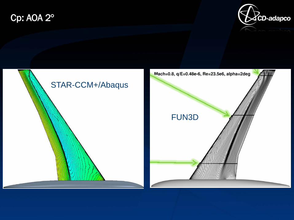
Cp: AOA 2°
FUN3D
STAR-CCM+/Abaqus

Cp: AOA 2°, Station 7
x/c
STAR-CCM+/Abaqus NASA FUN3D

Wind-off Vibration Modes : Abaqus vs Experiment
f=25.55 Hz (26.25)
f=80.25 Hz (78.20)
f=106.20 Hz
f=160.35 Hz (165.25)
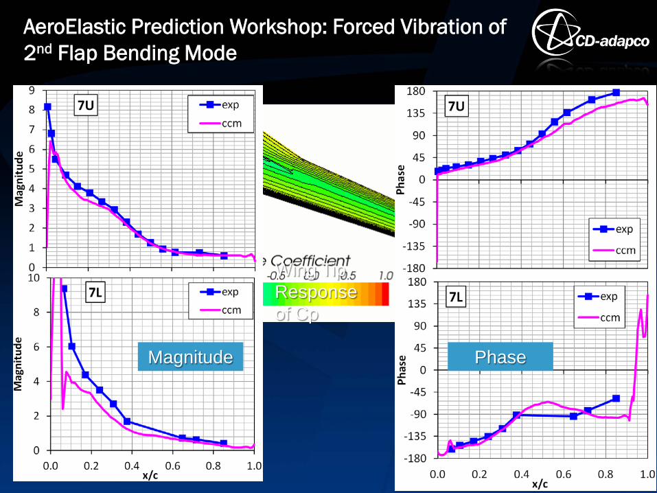
AeroElastic Prediction Workshop: Forced Vibration of 2nd Flap Bending Mode
Magnitude
Wing Tip Response of Cp
Phase

Fluid-Elastic Instabilities in a Tube Bundle
Weaver & Abd-Rabbo, “A Flow Visualization Study of a Square Array of Tubes in Water Crossflow”
31
HydroDynamic Damping: Simulation vs Measured Vibration RMS vs Inlet Velocity: Simulation vs Measured Tube Bundle Vorticity

Co-Simulation DOT Tank Impact
32 Experimental Test Impact

DOT Tank Impact Simulations
33
Von Mises Stress (Abaqus Explicit)
STAR-CCM+ Pressure

34
DOT Tank Impact Comparisons

Mapping Data Techniques Procedures for Exchanging Data Coupling Methods Dynamic Fluid Mesh Evolution Validations
The Challenges of FSI
35

Thank You For Your Attention & Enjoy
36