Embed Size (px)
Citation preview

Medium Pressure Filters
15/40/80CN SeriesMAX 600 I/min - 70 bar
Medium pressure filters
FEATURING
81
Medium Pressure Filters
15/40/80CN Series
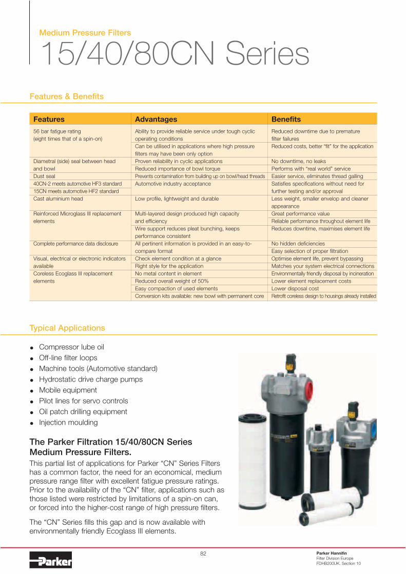
Typical Applications
Compressor lube oilOff-line filter loopsMachine tools (Automotive standard)Hydrostatic drive charge pumpsMobile equipmentPilot lines for servo controlsOil patch drilling equipmentInjection moulding
The Parker Filtration 15/40/80CN SeriesMedium Pressure Filters.This partial list of applications for Parker “CN” Series Filtershas a common factor, the need for an economical, mediumpressure range filter with excellent fatigue pressure ratings.Prior to the availability of the “CN” filter, applications such asthose listed were restricted by limitations of a spin-on can,or forced into the higher-cost range of high pressure filters.
The “CN” Series fills this gap and is now available withenvironmentally friendly Ecoglass III elements.
Features & Benefits
Parker HannifinFilter Division EuropeFDHB200UK. Section 10
82
Features
56 bar fatigue rating (eight times that of a spin-on)
Diametral (side) seal between head and bowlDust seal40CN-2 meets automotive HF3 standard15CN meets automotive HF2 standardCast aluminium head
Reinforced Microglass III replacementelements
Complete performance data disclosure
Visual, electrical or electronic indicatorsavailableCoreless Ecoglass III replacementelements
Advantages
Ability to provide reliable service under tough cyclicoperating conditionsCan be utilised in applications where high pressurefilters may have been only optionProven reliability in cyclic applicationsReduced importance of bowl torquePrevents contamination from building up on bowl/head threadsAutomotive industry acceptance
Low profile, lightweight and durable
Multi-layered design produced high capacity and efficiencyWire support reduces pleat bunching, keepsperformance consistentAll pertinent information is provided in an easy-to-compare formatCheck element condition at a glanceRight style for the applicationNo metal content in elementReduced overall weight of 50%Easy compaction of used elementsConversion kits available: new bowl with permanent core
Benefits
Reduced downtime due to premature filter failuresReduced costs, better “fit” for the application
No downtime, no leaksPerforms with “real world” serviceEasier service, eliminates thread gallingSatisfies specifications without need forfurther testing and/or approvalLess weight, smaller envelop and cleanerappearanceGreat performance valueReliable performance throughout element lifeReduces downtime, maximises element life
No hidden deficienciesEasy selection of proper filtrationOptimise element life, prevent bypassingMatches your system electrical connectionsEnvironmentally friendly disposal by incinerationLower element replacement costsLower disposal costRetrofit coreless design to housings already installed
Medium pressure filters
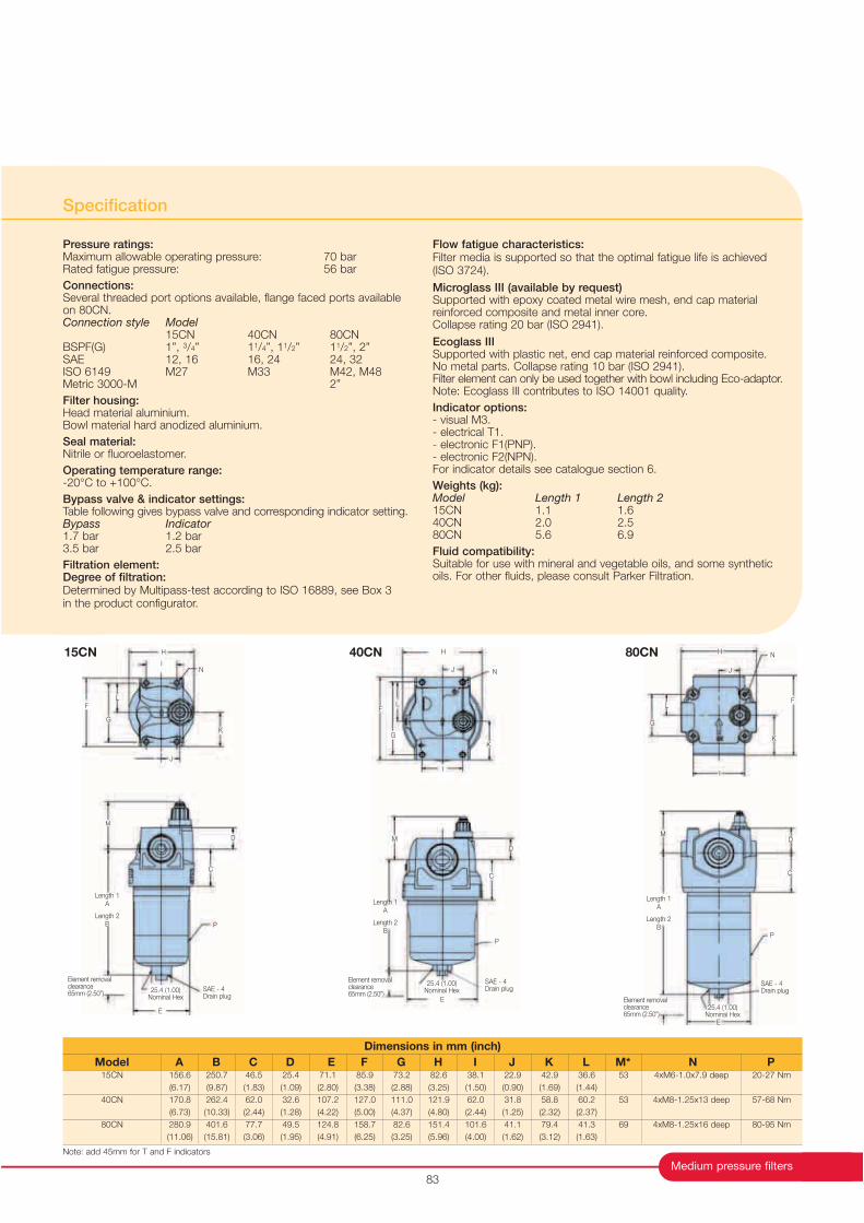
Specification
Flow fatigue characteristics:Filter media is supported so that the optimal fatigue life is achieved(ISO 3724).
Microglass III (available by request)Supported with epoxy coated metal wire mesh, end cap materialreinforced composite and metal inner core. Collapse rating 20 bar (ISO 2941).
Ecoglass IIISupported with plastic net, end cap material reinforced composite. No metal parts. Collapse rating 10 bar (ISO 2941).Filter element can only be used together with bowl including Eco-adaptor.Note: Ecoglass III contributes to ISO 14001 quality.Indicator options:- visual M3.- electrical T1.- electronic F1(PNP).- electronic F2(NPN).For indicator details see catalogue section 6.Weights (kg):Model Length 1 Length 215CN 1.1 1.640CN 2.0 2.580CN 5.6 6.9Fluid compatibility:Suitable for use with mineral and vegetable oils, and some syntheticoils. For other fluids, please consult Parker Filtration.
83
15CN
40CN
80CN
156.6(6.17)170.8(6.73)280.9(11.06)
250.7(9.87)262.4(10.33)401.6(15.81)
46.5(1.83)62.0(2.44)77.7(3.06)
25.4(1.09)32.6(1.28)49.5(1.95)
71.1(2.80)107.2(4.22)124.8(4.91)
85.9(3.38)127.0(5.00)158.7(6.25)
73.2(2.88)111.0(4.37)82.6(3.25)
82.6(3.25)121.9(4.80)151.4(5.96)
38.1(1.50)62.0(2.44)101.6(4.00)
22.9(0.90)31.8(1.25)41.1(1.62)
42.9(1.69)58.8(2.32)79.4(3.12)
36.6(1.44)60.2(2.37)41.3(1.63)
53
53
69
4xM6-1.0x7.9 deep
4xM8-1.25x13 deep
4xM8-1.25x16 deep
20-27 Nm
57-68 Nm
80-95 Nm
Dimensions in mm (inch)Model A B C D E F G H I J K L M* N P
H
I
F
G
L
J
K
N
D
C
E
Length 1A
Length 2B P
SAE - 4Drain plug
Element removalclearance65mm (2.50”) 25.4 (1.00)
Nominal Hex
H
J
F
G
N
K
I
L
15CN 80CN40CN
Length 1A
Length 2B
Element removalclearance65mm (2.50”)
SAE - 4Drain plug
25.4 (1.00)Nominal Hex
P
D
C
H
J
G
L
K
F
I
N
SAE - 4Drain plug
P
25.4 (1.00)Nominal Hex
E
C
DM
Length 1A
Length 2B
Element removalclearance65mm (2.50”)
M
M
E
Note: add 45mm for T and F indicators
Pressure ratings:Maximum allowable operating pressure: 70 barRated fatigue pressure: 56 barConnections:Several threaded port options available, flange faced ports availableon 80CN.Connection style Model
15CN 40CN 80CNBSPF(G) 1”, 3/4” 11/4”, 11/2” 11/2”, 2”SAE 12, 16 16, 24 24, 32ISO 6149 M27 M33 M42, M48Metric 3000-M 2”Filter housing:Head material aluminium.Bowl material hard anodized aluminium.Seal material:Nitrile or fluoroelastomer.Operating temperature range:-20°C to +100°C.Bypass valve & indicator settings:Table following gives bypass valve and corresponding indicator setting.Bypass Indicator1.7 bar 1.2 bar3.5 bar 2.5 barFiltration element:Degree of filtration:Determined by Multipass-test according to ISO 16889, see Box 3 in the product configurator.
Medium Pressure Filters
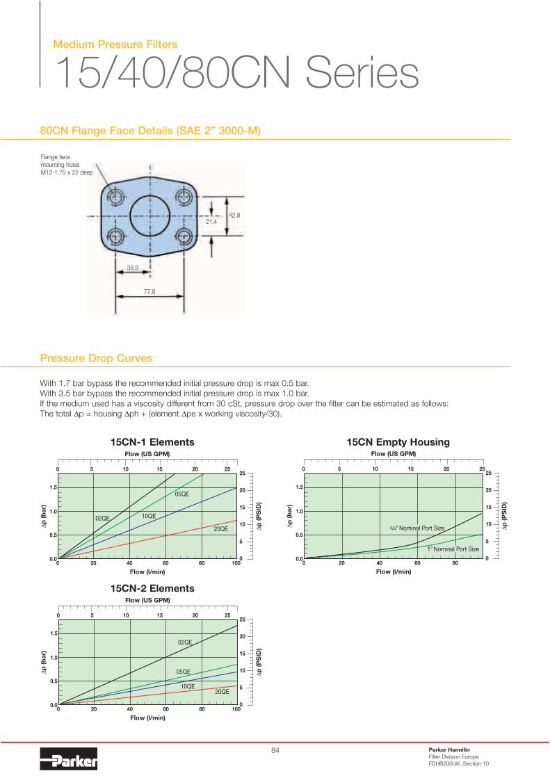
15/40/80CN Series80CN Flange Face Details (SAE 2” 3000-M)
Parker HannifinFilter Division EuropeFDHB200UK. Section 10
84
38.9
77.8
21.442.8
Flange facemounting holesM12-1.75 x 22 deep
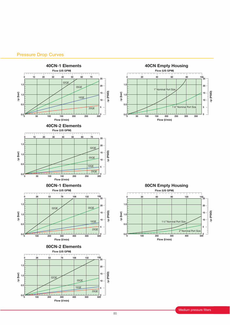
Pressure Drop Curves
With 1.7 bar bypass the recommended initial pressure drop is max 0.5 bar.With 3.5 bar bypass the recommended initial pressure drop is max 1.0 bar.If the medium used has a viscosity different from 30 cSt, pressure drop over the filter can be estimated as follows:The total Δp = housing Δph + (element Δpe x working viscosity/30).
15CN-2 Elements
15CN-1 Elements 15CN Empty Housing
25
20
15
5
0
10
Flow (US GPM)
Flow (l/min)20 40 60
0.0
Δp (b
ar)
0.5
1.0
1.5
0
10 15 20 2550
80 100
02QE
05QE
20QE10QE
Δp (P
SID
)
25
20
15
5
0
10
Flow (US GPM)
Flow (l/min)20 40 60
0.0
Δp (b
ar)
0.5
1.0
1.5
0
0 5 10 15 20 25
80
3/4” Nominal Port Size
1” Nominal Port Size
Δp (P
SID
)
25
20
15
5
0
10
Flow (US GPM)
Flow (l/min)20 40 60
0.0
Δp (b
ar)
0.5
1.0
1.5
0
10 15 20 2550
80 100
02QE
05QE
20QE
10QE
Δp (P
SID
)
Medium pressure filters
Pressure Drop Curves
85
80CN-1 Elements
80CN-2 Elements
40CN-2 Elements
80CN Empty Housing
25
20
15
5
0
10
Flow (US GPM)
Flow (l/min)
0.0
Δp (b
ar)
0.5
1.0
1.5
02QE 05QE
20QE
10QE Δp (P
SID
)
0 100 200 300 400 500 600
0 26 53 79 106 132 159
25
20
15
5
0
10
Flow (US GPM)
Flow (l/min)
0.0
Δp (b
ar)
0.5
1.0
1.5
02QE05QE
20QE
10QE
Δp (P
SID
)
0 100 200 300 400 500 600
0 26 53 79 106 132 159
25
20
15
5
0
10
Flow (US GPM)
Flow (l/min)
0.0
Δp (b
ar)
0.5
1.0
1.5
02QE
05QE
20QE
10QE
Δp (P
SID
)
0 70
50 100 150 200 250 3000
10 20 30 40 50 60
40CN Empty Housing
25
20
15
5
0
10
0 20 40 60 100
Flow (US GPM)
Flow (l/min)50 100 150 200 250 300 350
0.0
Δp (b
ar)
0.5
1.0
1.5
0
80
11/2” Nominal Port Size
1” Nominal Port Size
Δp (P
SID
)
25
20
15
5
0
10
0 30 60 90 150
Flow (US GPM)
Flow (l/min)100 200 300 400
0.0
Δp (b
ar)
0.5
1.0
1.5
0
120
500
11/2” Nominal Port Size
2” Nominal Port Size
Δp (P
SID
)
40CN-1 Elements
25
20
15
5
0
10
0 70
Flow (US GPM)
Flow (l/min)50 100 150 200 250 300
0.0
Δp (b
ar)
0.5
1.0
1.5
0
10 20 30 40 50 60
02QE
05QE
20QE
10QE
Δp (P
SID
)
Medium Pressure Filters
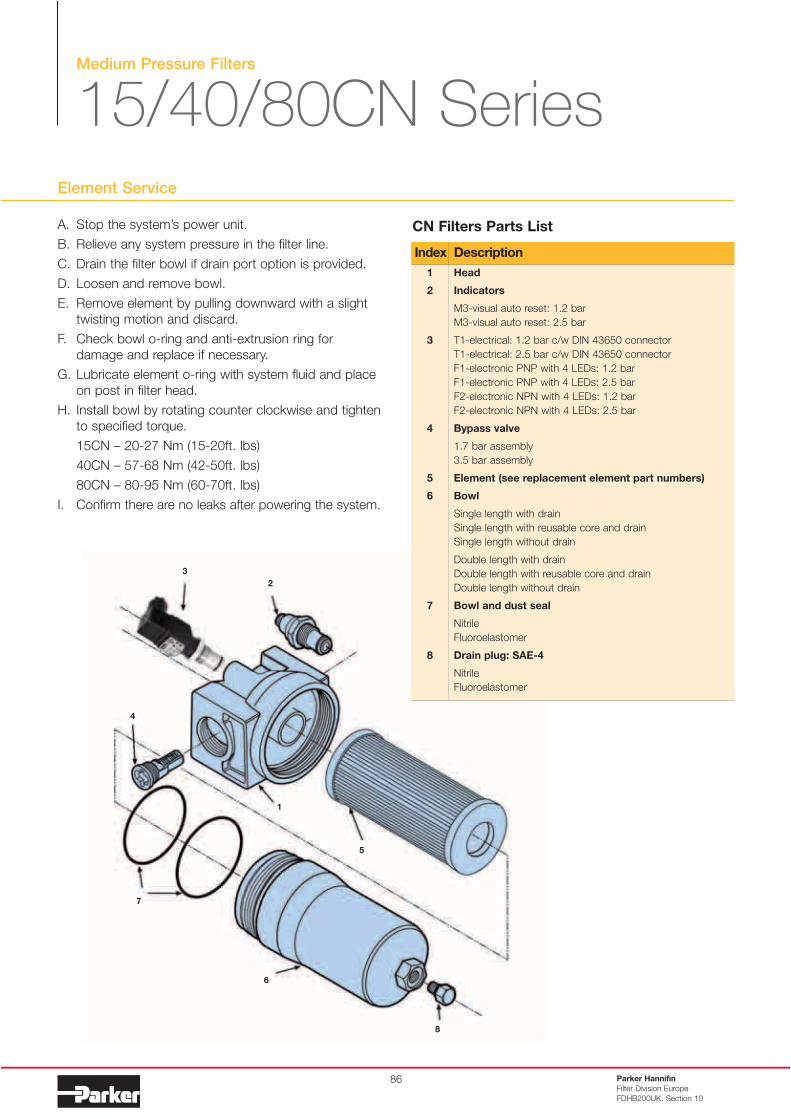
15/40/80CN SeriesElement Service
8
32
1
6
5
4
7
A. Stop the system’s power unit.
B. Relieve any system pressure in the filter line.
C. Drain the filter bowl if drain port option is provided.
D. Loosen and remove bowl.
E. Remove element by pulling downward with a slighttwisting motion and discard.
F. Check bowl o-ring and anti-extrusion ring fordamage and replace if necessary.
G. Lubricate element o-ring with system fluid and placeon post in filter head.
H. Install bowl by rotating counter clockwise and tightento specified torque.
15CN – 20-27 Nm (15-20ft. lbs)
40CN – 57-68 Nm (42-50ft. lbs)
80CN – 80-95 Nm (60-70ft. lbs)
I. Confirm there are no leaks after powering the system.
Parker HannifinFilter Division EuropeFDHB200UK. Section 10
86
Head
Indicators
M3-visual auto reset: 1.2 barM3-visual auto reset: 2.5 bar
T1-electrical: 1.2 bar c/w DIN 43650 connectorT1-electrical: 2.5 bar c/w DIN 43650 connectorF1-electronic PNP with 4 LEDs: 1.2 barF1-electronic PNP with 4 LEDs: 2.5 barF2-electronic NPN with 4 LEDs: 1.2 barF2-electronic NPN with 4 LEDs: 2.5 bar
Bypass valve
1.7 bar assembly3.5 bar assembly
Element (see replacement element part numbers)
Bowl
Single length with drainSingle length with reusable core and drainSingle length without drain
Double length with drainDouble length with reusable core and drainDouble length without drain
Bowl and dust seal
NitrileFluoroelastomer
Drain plug: SAE-4
NitrileFluoroelastomer
1
2
3
4
5
6
7
8
Index Description
CN Filters Parts List
Medium pressure filters
Ordering Information
87
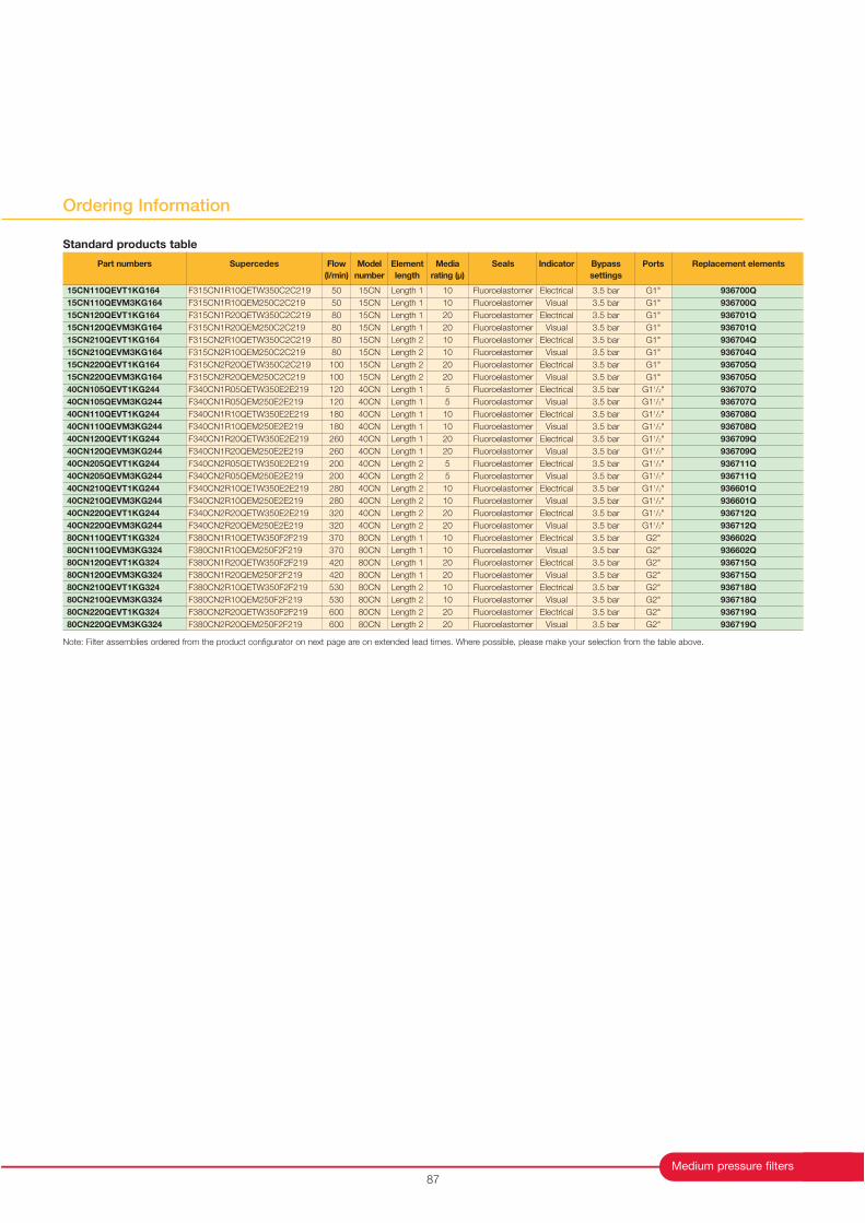
Note: Filter assemblies ordered from the product configurator on next page are on extended lead times. Where possible, please make your selection from the table above.
Part numbers
15CN110QEVT1KG16415CN110QEVM3KG16415CN120QEVT1KG16415CN120QEVM3KG16415CN210QEVT1KG16415CN210QEVM3KG16415CN220QEVT1KG16415CN220QEVM3KG16440CN105QEVT1KG24440CN105QEVM3KG24440CN110QEVT1KG24440CN110QEVM3KG24440CN120QEVT1KG24440CN120QEVM3KG24440CN205QEVT1KG24440CN205QEVM3KG24440CN210QEVT1KG24440CN210QEVM3KG24440CN220QEVT1KG24440CN220QEVM3KG24480CN110QEVT1KG32480CN110QEVM3KG32480CN120QEVT1KG32480CN120QEVM3KG32480CN210QEVT1KG32480CN210QEVM3KG32480CN220QEVT1KG32480CN220QEVM3KG324
Supercedes
F315CN1R10QETW350C2C219F315CN1R10QEM250C2C219F315CN1R20QETW350C2C219F315CN1R20QEM250C2C219F315CN2R10QETW350C2C219F315CN2R10QEM250C2C219F315CN2R20QETW350C2C219F315CN2R20QEM250C2C219F340CN1R05QETW350E2E219F340CN1R05QEM250E2E219F340CN1R10QETW350E2E219F340CN1R10QEM250E2E219F340CN1R20QETW350E2E219F340CN1R20QEM250E2E219F340CN2R05QETW350E2E219F340CN2R05QEM250E2E219F340CN2R10QETW350E2E219F340CN2R10QEM250E2E219F340CN2R20QETW350E2E219F340CN2R20QEM250E2E219F380CN1R10QETW350F2F219F380CN1R10QEM250F2F219F380CN1R20QETW350F2F219F380CN1R20QEM250F2F219F380CN2R10QETW350F2F219F380CN2R10QEM250F2F219F380CN2R20QETW350F2F219F380CN2R20QEM250F2F219
Flow(l/min)
505080808080100100120120180180260260200200280280320320370370420420530530600600
Modelnumber
15CN15CN15CN15CN15CN15CN15CN15CN40CN40CN40CN40CN40CN40CN40CN40CN40CN40CN40CN40CN80CN80CN80CN80CN80CN80CN80CN80CN
Elementlength
Length 1Length 1Length 1Length 1Length 2Length 2Length 2Length 2Length 1Length 1Length 1Length 1Length 1Length 1Length 2Length 2Length 2Length 2Length 2Length 2Length 1Length 1Length 1Length 1Length 2Length 2Length 2Length 2
Mediarating (μ)
1010202010102020551010202055101020201010202010102020
Seals
FluoroelastomerFluoroelastomerFluoroelastomerFluoroelastomerFluoroelastomerFluoroelastomerFluoroelastomerFluoroelastomerFluoroelastomerFluoroelastomerFluoroelastomerFluoroelastomerFluoroelastomerFluoroelastomerFluoroelastomerFluoroelastomerFluoroelastomerFluoroelastomerFluoroelastomerFluoroelastomerFluoroelastomerFluoroelastomerFluoroelastomerFluoroelastomerFluoroelastomerFluoroelastomerFluoroelastomerFluoroelastomer
Indicator
ElectricalVisual
ElectricalVisual
ElectricalVisual
ElectricalVisual
ElectricalVisual
ElectricalVisual
ElectricalVisual
ElectricalVisual
ElectricalVisual
ElectricalVisual
ElectricalVisual
ElectricalVisual
ElectricalVisual
ElectricalVisual
Bypasssettings
3.5 bar3.5 bar3.5 bar3.5 bar3.5 bar3.5 bar3.5 bar3.5 bar3.5 bar3.5 bar3.5 bar3.5 bar3.5 bar3.5 bar3.5 bar3.5 bar3.5 bar3.5 bar3.5 bar3.5 bar3.5 bar3.5 bar3.5 bar3.5 bar3.5 bar3.5 bar3.5 bar3.5 bar
Replacement elements
936700Q936700Q936701Q936701Q936704Q936704Q936705Q936705Q936707Q936707Q936708Q936708Q936709Q936709Q936711Q936711Q936601Q936601Q936712Q936712Q936602Q936602Q936715Q936715Q936718Q936718Q936719Q936719Q
Ports
G1"G1"G1"G1"G1"G1"G1"G1"
G11/2"G11/2"G11/2"G11/2"G11/2"G11/2"G11/2"G11/2"G11/2"G11/2"G11/2"G11/2"G2"G2"G2"G2"G2"G2"G2"G2"
Standard products table
Medium Pressure Filters
15/40/80CN Series
Parker HannifinFilter Division EuropeFDHB200UK. Section 10
88
* Fluoroelastomers are available under various registered trademarks,including Viton (a registered trademark of DuPont) and Fluorel (a registeredtrademark of 3M)
02Q928935Q928953Q926696Q926697Q932656Q932662Q
05QG04041QG04169QG04048QG04167Q932657Q932663Q
10Q928934Q928952Q926835Q926837Q932658Q932664Q
20Q930367Q930368Q930099Q930118Q929899Q929923Q
Model15CN-115CN-240CN-140CN-280CN-180CN-2
Elements with nitrile seals02Q
932610Q932616Q926716Q926717Q932659Q932665Q
05QG04189QG04190QG04191QG04192Q932660Q932666Q
10Q932612Q932618Q926836Q926838Q832661Q932667Q
20Q930369Q930370Q930100Q930119Q929903Q929927Q
Model15CN-115CN-240CN-140CN-280CN-180CN-2
Elements with Fluoroelastomer seals
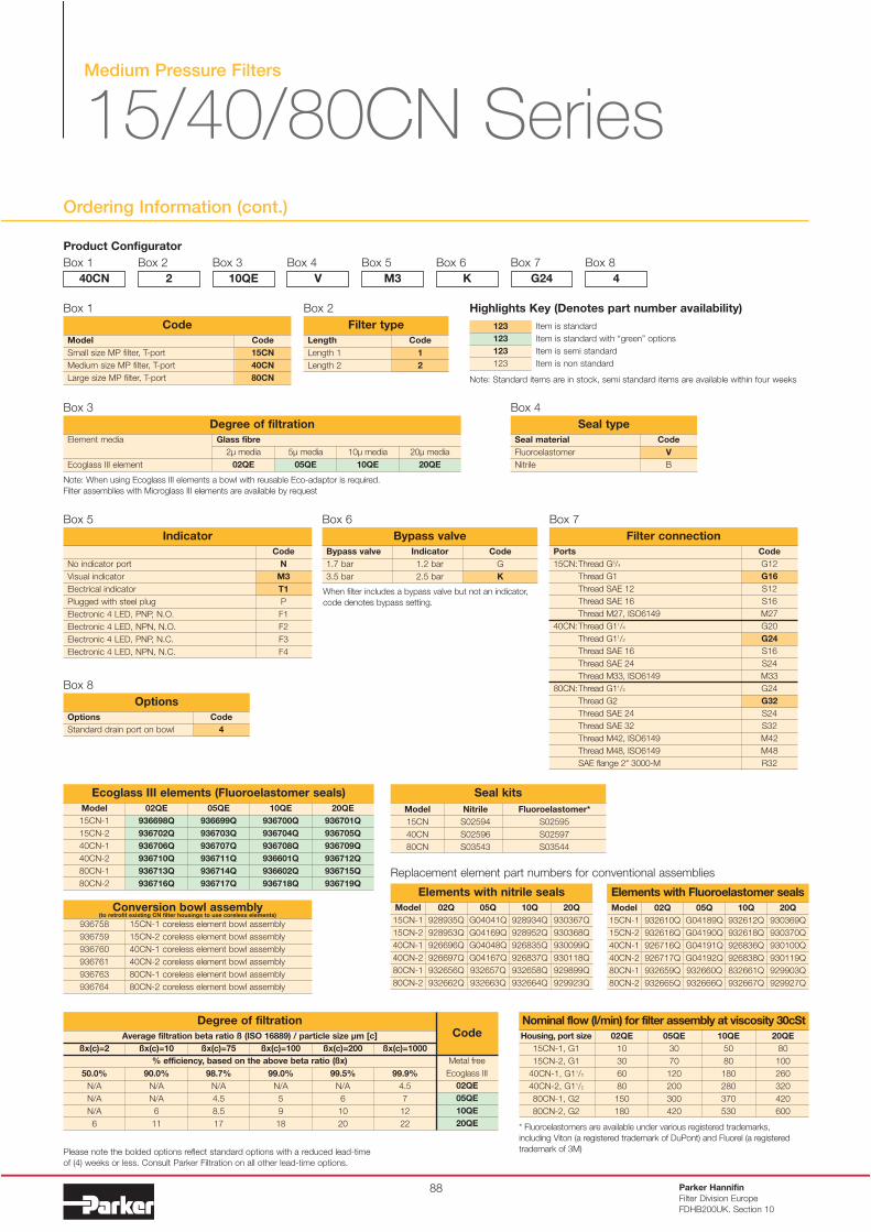
02QE10306080150180
05QE3070120200300420
10QE5080180280370530
20QE80100260320420600
Housing, port size15CN-1, G115CN-2, G1
40CN-1, G11/2
40CN-2, G11/2
80CN-1, G280CN-2, G2
Nominal flow (l/min) for filter assembly at viscosity 30cSt
Ordering Information (cont.)
Product ConfiguratorBox 1
Code12
LengthLength 1Length 2
Filter typeBox 2
40CNBox 2
2Box 3
10QEBox 4
VBox 5
M3Box 6
KBox 7
G24Box 8
4
Please note the bolded options reflect standard options with a reduced lead-timeof (4) weeks or less. Consult Parker Filtration on all other lead-time options.
CodeVB
Seal materialFluoroelastomerNitrile
Seal typeBox 4
Bypass valve1.7 bar3.5 bar
Bypass valveIndicator
1.2 bar2.5 bar
CodeGK
Box 6
CodeN
M3T1PF1F2F3F4
No indicator portVisual indicatorElectrical indicatorPlugged with steel plugElectronic 4 LED, PNP, N.O.Electronic 4 LED, NPN, N.O.Electronic 4 LED, PNP, N.C.Electronic 4 LED, NPN, N.C.
IndicatorBox 5
CodeG12G16S12S16M27G20G24S16S24M33G24G32S24S32M42M48R32
Ports15CN:Thread G3/4
Thread G1Thread SAE 12Thread SAE 16Thread M27, ISO6149
40CN:Thread G11/4
Thread G11/2
Thread SAE 16Thread SAE 24Thread M33, ISO6149
80CN:Thread G11/2
Thread G2Thread SAE 24Thread SAE 32Thread M42, ISO6149Thread M48, ISO6149SAE flange 2" 3000-M
Filter connectionBox 7
Code4
OptionsStandard drain port on bowl
OptionsBox 8
Code15CN40CN80CN
ModelSmall size MP filter, T-portMedium size MP filter, T-portLarge size MP filter, T-port
CodeBox 1
Note: When using Ecoglass III elements a bowl with reusable Eco-adaptor is required.Filter assemblies with Microglass III elements are available by request
Model15CN-115CN-240CN-140CN-280CN-180CN-2
Ecoglass III elements (Fluoroelastomer seals)02QE
936698Q936702Q936706Q936710Q936713Q936716Q
05QE936699Q936703Q936707Q936711Q936714Q936717Q
10QE936700Q936704Q936708Q936601Q936602Q936718Q
20QE936701Q936705Q936709Q936712Q936715Q936719Q
936758936759936760936761936763936764
Conversion bowl assembly15CN-1 coreless element bowl assembly15CN-2 coreless element bowl assembly40CN-1 coreless element bowl assembly40CN-2 coreless element bowl assembly80CN-1 coreless element bowl assembly80CN-2 coreless element bowl assembly
(to retrofit existing CN filter housings to use coreless elements)
Model15CN40CN80CN
Seal kitsNitrile
S02594S02596S03543
Fluoroelastomer*S02595S02597S03544
Replacement element part numbers for conventional assemblies
When filter includes a bypass valve but not an indicator,code denotes bypass setting.
Item is standardItem is standard with “green” optionsItem is semi standardItem is non standard
123123123123
Highlights Key (Denotes part number availability)
Note: Standard items are in stock, semi standard items are available within four weeks
Box 3
Element media
Ecoglass III element20μ media
20QE10μ media
10QE5μ media
05QE2μ media
02QE
Glass fibre
Degree of filtration
Average filtration beta ratio ß (ISO 16889) / particle size μm [c]
% efficiency, based on the above beta ratio (ßx)ßx(c)=2
50.0%N/AN/AN/A6
Degree of filtrationCode
ßx(c)=10
90.0%N/AN/A611
ßx(c)=75
98.7%N/A4.58.517
ßx(c)=100
99.0%N/A5918
ßx(c)=200
99.5%N/A61020
ßx(c)=1000
99.9%4.571222
02QE05QE10QE20QE
Metal freeEcoglass III

Medium Pressure Filters
45M/45M Eco SeriesMAX 260 I/min - 40 bar
89Medium pressure filters
FEATURING
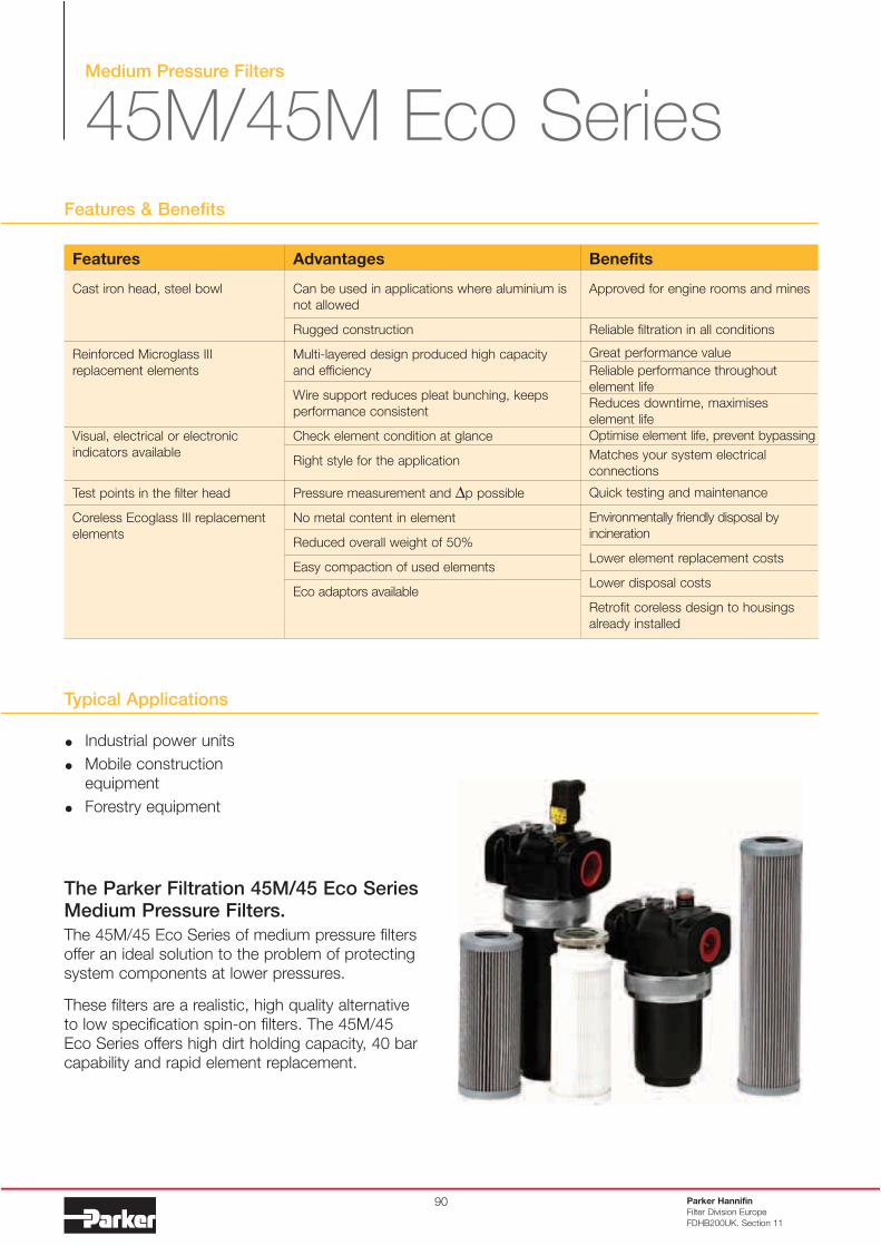
Medium Pressure Filters
45M/45M Eco Series
Typical Applications
Industrial power unitsMobile constructionequipmentForestry equipment
The Parker Filtration 45M/45 Eco Series Medium Pressure Filters.The 45M/45 Eco Series of medium pressure filtersoffer an ideal solution to the problem of protectingsystem components at lower pressures.
These filters are a realistic, high quality alternativeto low specification spin-on filters. The 45M/45Eco Series offers high dirt holding capacity, 40 barcapability and rapid element replacement.
Features & Benefits
Parker HannifinFilter Division EuropeFDHB200UK. Section 11
90
Features
Cast iron head, steel bowl
Reinforced Microglass IIIreplacement elements
Visual, electrical or electronicindicators available
Test points in the filter head
Coreless Ecoglass III replacementelements
Advantages
Can be used in applications where aluminium isnot allowed
Rugged construction
Multi-layered design produced high capacity and efficiency
Wire support reduces pleat bunching, keepsperformance consistent
Check element condition at glance
Right style for the application
Pressure measurement and Δp possible
No metal content in element
Reduced overall weight of 50%
Easy compaction of used elements
Eco adaptors available
Benefits
Approved for engine rooms and mines
Reliable filtration in all conditions
Great performance valueReliable performance throughoutelement lifeReduces downtime, maximises element lifeOptimise element life, prevent bypassingMatches your system electricalconnections
Quick testing and maintenance
Environmentally friendly disposal byincineration
Lower element replacement costs
Lower disposal costs
Retrofit coreless design to housingsalready installed
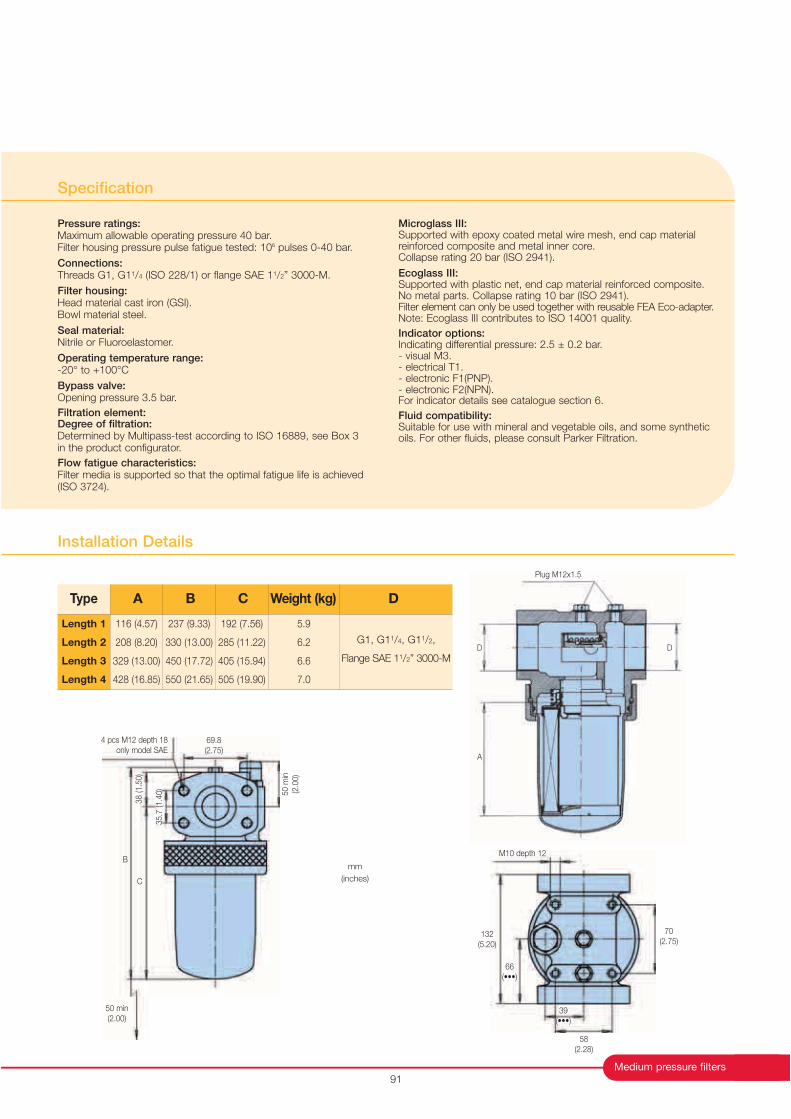
Type
116 (4.57)
208 (8.20)
329 (13.00)
428 (16.85)
237 (9.33)
330 (13.00)
450 (17.72)
550 (21.65)
192 (7.56)
285 (11.22)
405 (15.94)
505 (19.90)
G1, G11/4, G11/2,
Flange SAE 11/2” 3000-M
Length 1
Length 2
Length 3
Length 4
A B C Weight (kg) D
5.9
6.2
6.6
7.0
38 (1
.50)
C
B
50 min(2.00)
Plug M12x1.5
DD
A
70(2.75)
132(5.20)
58(2.28)
M10 depth 12
69.8(2.75)
4 pcs M12 depth 18only model SAE
35.7
(1.4
0)
mm(inches)
Medium pressure filters
Installation Details
Specification
Pressure ratings:Maximum allowable operating pressure 40 bar.Filter housing pressure pulse fatigue tested: 106 pulses 0-40 bar.
Connections:Threads G1, G11/4 (ISO 228/1) or flange SAE 11/2” 3000-M.
Filter housing:Head material cast iron (GSI).Bowl material steel.
Seal material:Nitrile or Fluoroelastomer.
Operating temperature range:-20° to +100°C
Bypass valve:Opening pressure 3.5 bar.Filtration element:Degree of filtration:Determined by Multipass-test according to ISO 16889, see Box 3 in the product configurator.Flow fatigue characteristics:Filter media is supported so that the optimal fatigue life is achieved(ISO 3724).
Microglass III: Supported with epoxy coated metal wire mesh, end cap materialreinforced composite and metal inner core. Collapse rating 20 bar (ISO 2941).
Ecoglass III:Supported with plastic net, end cap material reinforced composite. No metal parts. Collapse rating 10 bar (ISO 2941).Filter element can only be used together with reusable FEA Eco-adapter.Note: Ecoglass III contributes to ISO 14001 quality.Indicator options:Indicating differential pressure: 2.5 ± 0.2 bar.- visual M3.- electrical T1.- electronic F1(PNP).- electronic F2(NPN).For indicator details see catalogue section 6.Fluid compatibility:Suitable for use with mineral and vegetable oils, and some syntheticoils. For other fluids, please consult Parker Filtration.
91
50 m
in(2
.00)
39(•••)
66(•••)

Medium Pressure Filters
45M/45M Eco SeriesPressure Drop Curves
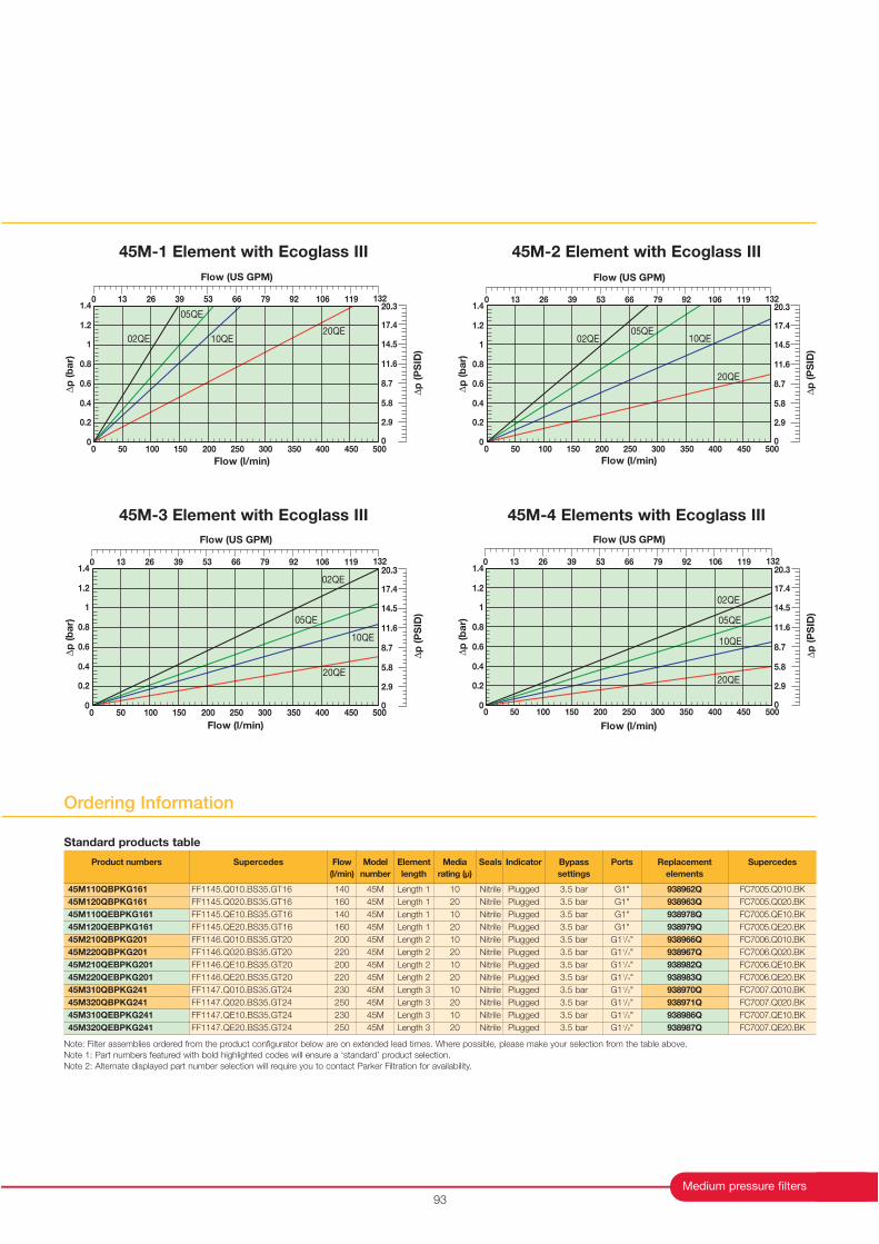
The recommended level of the initial pressure drop is max 1.0 bar.If the medium used has a viscosity different from 30 cSt, pressure drop over the filter can be estimated as follows:The total Δp = housing Δph + (element Δpe x working viscosity/30).
Parker HannifinFilter Division EuropeFDHB200UK. Section 11
92
45M-1 Element with Microglass III
45M-3 Element with Microglass III
45M Series Empty Housing
45M-2 Element with Microglass III
45M-4 Element with Microglass III
0
0.2
0.4
0.6
0.8
1
1.2
1.4
0 50 100 150 200 250 300 350 400 450 500Flow (l/min)
02Q
Δp (b
ar)
05Q 10Q 20Q
Δp (P
SID
)
0
2.9
5.8
8.7
11.6
14.5
17.4
20.3
Flow (US GPM)
0 13 26 39 53 66 79 92 106 119 132
0
0.2
0.4
0.6
0.8
1
1.2
1.4
0 50 100 150 200 250 300 350 400 450 500Flow (l/min)
02Q
Δp (b
ar)
05Q
10Q
20Q
Δp (P
SID
)
0
2.9
5.8
8.7
11.6
14.5
17.4
20.3
Flow (US GPM)
0 13 26 39 53 66 79 92 106 119 132
0
0.2
0.4
0.6
0.8
1
1.2
1.4
0 50 100 150 200 250 300 350 400 450 500Flow (l/min)
02Q
Δp (b
ar)
05Q
10Q
20Q Δp (P
SID
)
0
2.9
5.8
8.7
11.6
14.5
17.4
20.3
Flow (US GPM)
0 13 26 39 53 66 79 92 106 119 132
0
0.2
0.4
0.6
0.8
1
1.2
1.4
1.6
0 25 50 75 100 125 150 175 200 225 250
G24R24
G20G16
23.2
20.3
14.5
2.9
0
8.7 Δp (P
SID
)
Flow (l/min)
Δp (b
ar)
0 6.3 32.3 53 66
Flow (US GPM)
13 19.3 26 39 45.3 59.3
5.8
11.6
17.4
0
0.2
0.4
0.6
0.8
1
1.2
1.4
0 50 100 150 200 250 300 350 400 450 500Flow (l/min)
02Q
Δp (b
ar) 05Q
10Q
20Q Δp (P
SID
)
Flow (US GPM)
0
2.9
5.8
8.7
11.6
14.5
17.4
20.30 13 26 39 53 66 79 92 106 119 132
Medium pressure filters93
45M-1 Element with Ecoglass III
45M-3 Element with Ecoglass III 45M-4 Elements with Ecoglass III
45M-2 Element with Ecoglass III
0
0.2
0.4
0.6
0.8
1
1.2
1.4
0 50 100 150 200 250 300 350 400 450 500Flow (l/min)
02QE
Δp (b
ar)
05QE
10QE20QE
Δp (P
SID
)
0
2.9
5.8
8.7
11.6
14.5
17.4
20.3
Flow (US GPM)
0 13 26 39 53 66 79 92 106 119 132
0
0.2
0.4
0.6
0.8
1
1.2
1.4
0 50 100 150 200 250 300 350 400 450 500Flow (l/min)
02QE
Δp (b
ar)
05QE10QE
20QE
Δp (P
SID
)
0
2.9
5.8
8.7
11.6
14.5
17.4
20.3
Flow (US GPM)
0 13 26 39 53 66 79 92 106 119 132
0
0.2
0.4
0.6
0.8
1
1.2
1.4
0 50 100 150 200 250 300 350 400 450 500Flow (l/min)
02QE
Δp (b
ar) 05QE
10QE
20QE
Δp (P
SID
)
0
2.9
5.8
8.7
11.6
14.5
17.4
20.3
Flow (US GPM)
0 13 26 39 53 66 79 92 106 119 132
0
0.2
0.4
0.6
0.8
1
1.2
1.4
0 50 100 150 200 250 300 350 400 450 500
Flow (l/min)
02QE
Δp (b
ar) 05QE
10QE
20QE
Δp (P
SID
)
0
2.9
5.8
8.7
11.6
14.5
17.4
20.3
Flow (US GPM)
0 13 26 39 53 66 79 92 106 119 132
Ordering Information
Note: Filter assemblies ordered from the product configurator below are on extended lead times. Where possible, please make your selection from the table above.Note 1: Part numbers featured with bold highlighted codes will ensure a ‘standard’ product selection.Note 2: Alternate displayed part number selection will require you to contact Parker Filtration for availability.
Product numbers
45M110QBPKG16145M120QBPKG16145M110QEBPKG16145M120QEBPKG16145M210QBPKG20145M220QBPKG20145M210QEBPKG20145M220QEBPKG20145M310QBPKG24145M320QBPKG24145M310QEBPKG24145M320QEBPKG241
Supercedes
FF1145.Q010.BS35.GT16FF1145.Q020.BS35.GT16FF1145.QE10.BS35.GT16FF1145.QE20.BS35.GT16FF1146.Q010.BS35.GT20FF1146.Q020.BS35.GT20FF1146.QE10.BS35.GT20FF1146.QE20.BS35.GT20FF1147.Q010.BS35.GT24FF1147.Q020.BS35.GT24FF1147.QE10.BS35.GT24FF1147.QE20.BS35.GT24
Flow(l/min)
140160140160200220200220230250230250
Modelnumber
45M45M45M45M45M45M45M45M45M45M45M45M
Elementlength
Length 1Length 1Length 1Length 1Length 2Length 2Length 2Length 2Length 3Length 3Length 3Length 3
Mediarating (μ)
102010201020102010201020
Seals
NitrileNitrileNitrileNitrileNitrileNitrileNitrileNitrileNitrileNitrileNitrileNitrile
Indicator
PluggedPluggedPluggedPluggedPluggedPluggedPluggedPluggedPluggedPluggedPluggedPlugged
Bypasssettings
3.5 bar3.5 bar3.5 bar3.5 bar3.5 bar3.5 bar3.5 bar3.5 bar3.5 bar3.5 bar3.5 bar3.5 bar
Replacementelements
938962Q938963Q938978Q938979Q938966Q938967Q938982Q938983Q938970Q938971Q938986Q938987Q
Supercedes
FC7005.Q010.BKFC7005.Q020.BKFC7005.QE10.BKFC7005.QE20.BKFC7006.Q010.BKFC7006.Q020.BKFC7006.QE10.BKFC7006.QE20.BKFC7007.Q010.BKFC7007.Q020.BKFC7007.QE10.BKFC7007.QE20.BK
Ports
G1"G1"G1"G1"
G11/4"G11/4"G11/4"G11/4"G11/2"G11/2"G11/2"G11/2"
Standard products table
Medium Pressure Filters
45M/45M Eco SeriesOrdering Information (cont.)
Parker HannifinFilter Division EuropeFDHB200UK. Section 11
94
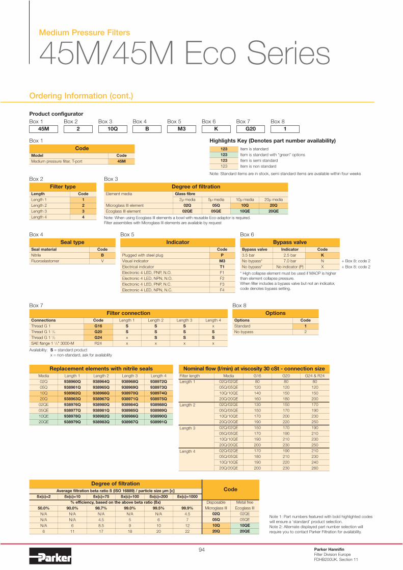
Product configuratorBox 1
Code1234
LengthLength 1Length 2Length 3Length 4
Filter typeBox 2
45MBox 2
2Box 3
10QBox 4
BBox 5
M3Box 6
KBox 7
G20Box 8
1
Note 1: Part numbers featured with bold highlighted codeswill ensure a ‘standard’ product selection.Note 2: Alternate displayed part number selection willrequire you to contact Parker Filtration for availability.
CodeBV
Seal materialNitrileFluoroelastomer
Seal typeBox 4
Bypass valve3.5 barNo bypass*No bypass*
Bypass valveIndicator
2.5 bar7.0 bar
No indicator (P)
CodeKNX
+ Box 8: code 2+ Box 8: code 2
Box 6
CodeP
M3T1F1F2F3F4
Plugged with steel plugVisual indicatorElectrical indicatorElectronic 4 LED, PNP, N.O.Electronic 4 LED, NPN, N.O.Electronic 4 LED, PNP, N.C.Electronic 4 LED, NPN, N.C.
IndicatorBox 5
CodeG16G20G24R24
ConnectionsThread G 1Thread G 1 1/4
Thread G 1 1/2
SAE flange 1 1/2" 3000-M
Filter connectionLength 1
SSxx
Length 2SSSx
Length 3SSSx
Length 4xSSx
Box 7
Code12
OptionsStandardNo bypass
OptionsBox 8
Code45M
ModelMedium pressure filter, T-port
CodeBox 1
* High collapse element must be used if MAOP is higherthan element collapse pressure.When filter includes a bypass valve but not an indicator,code denotes bypass setting.
Availability: S = standard productx = non-standard, ask for availability
Media02Q05Q10Q20Q
02QE05QE10QE20QE
Replacement elements with nitrile sealsLength 1938960Q938961Q938962Q938963Q938976Q938977Q938978Q938979Q
Length 2938964Q938965Q938966Q938967Q938980Q938981Q938982Q938983Q
Length 3938968Q938969Q938970Q938971Q938984Q938985Q938986Q938987Q
Length 4938972Q938973Q938974Q938975Q938988Q938989Q938990Q938991Q
Filter lengthLength 1
Length 2
Length 3
Length 4
Nominal flow (I/min) at viscosity 30 cSt - connection sizeMedia
02Q/02QE05Q/05QE10Q/10QE20Q/20QE02Q/02QE05Q/05QE10Q/10QE20Q/20QE02Q/02QE05Q/05QE10Q/10QE20Q/20QE02Q/02QE05Q/05QE10Q/10QE20Q/20QE
G1680
120140160130150170190150170190200170180190200
G2080
120150180150170200220170190210230190210220230
G24 & R2480
120150200170190230250190210230250210230240260
Item is standardItem is standard with “green” optionsItem is semi standardItem is non standard
123123123123
Highlights Key (Denotes part number availability)
Note: Standard items are in stock, semi standard items are available within four weeks
Note: When using Ecoglass III elements a bowl with reusable Eco-adaptor is required.Filter assemblies with Microglass III elements are available by request
Box 3
Element media
Microglass III elementEcoglass III element
20μ media20Q
20QE
10μ media10Q
10QE
5μ media05Q
05QE
2μ media02Q
02QE
Glass fibre
Degree of filtration
Average filtration beta ratio ß (ISO 16889) / particle size μm [c]
% efficiency, based on the above beta ratio (ßx)ßx(c)=2
50.0%N/AN/AN/A6
Degree of filtrationCode
ßx(c)=10
90.0%N/AN/A611
ßx(c)=75
98.7%N/A4.58.517
ßx(c)=100
99.0%N/A5918
ßx(c)=200
99.5%N/A61020
ßx(c)=1000
99.9%4.571222
02Q05Q10Q20Q
DisposableMicroglass III
02QE05QE10QE20QE
Metal freeEcoglass III
Medium Pressure Filters
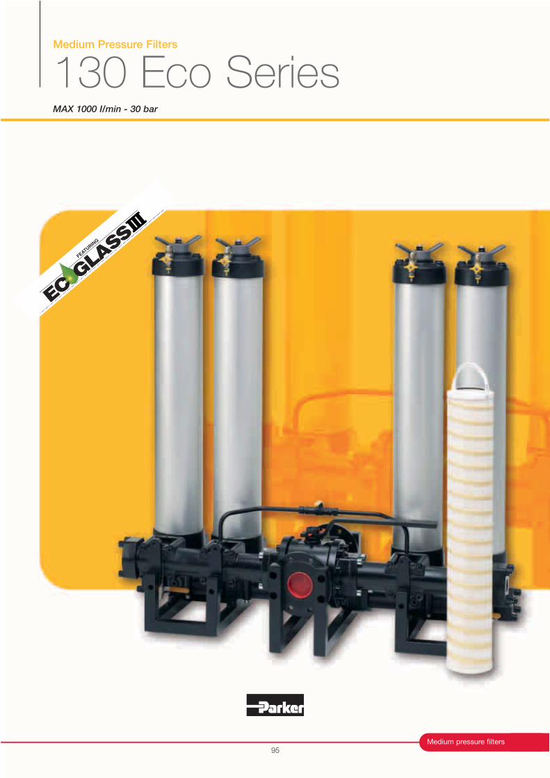
130 Eco SeriesMAX 1000 I/min - 30 bar
Medium pressure filters
FEATURING
95
Medium Pressure Filters
130 Eco Series
96
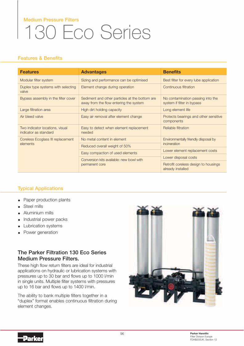
Typical Applications
Paper production plantsSteel millsAluminium millsIndustrial power packsLubrication systemsPower generation
Features & Benefits
Parker HannifinFilter Division EuropeFDHB200UK. Section 12
The Parker Filtration 130 Eco Series Medium Pressure Filters.These high flow return filters are ideal for industrialapplications on hydraulic or lubrication systems withpressures up to 30 bar and flows up to 1000 l/minin single units. Multiple filter systems with pressuresup to 16 bar and flows up to 1400 l/min.
The ability to bank multiple filters together in a“duplex” format enables continuous filtration duringelement changes.
Features
Modular filter system
Duplex type systems with selectingvalve
Bypass assembly in the filter cover
Large filtration area
Air bleed valve
Two indicator locations, visualindicator as standard
Coreless Ecoglass III replacementelements
Advantages
Sizing and performance can be optimised
Element change during operation
Sediment and other particles at the bottom areaway from the flow entering the system
High dirt holding capacity
Easy air removal after element change
Easy to detect when element replacementneeded
No metal content in element
Reduced overall weight of 50%
Easy compaction of used elements
Conversion kits available: new bowl withpermanent core
Benefits
Best filter for every lube application
Continuous filtration
No contamination passing into thesystem if filter in bypass
Long element life
Protects bearings and other sensitivecomponents
Reliable filtration
Environmentally friendly disposal byincineration
Lower element replacement costs
Lower disposal costs
Retrofit coreless design to housingsalready installed
Medium pressure filters
Installation Details
Specification
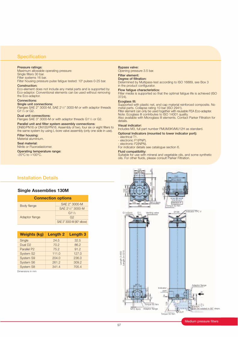
Pressure ratings:Maximum allowable operating pressure:Single filters 30 bar.Filter systems 16 bar.Filter housing pressure pulse fatigue tested: 106 pulses 0-25 bar.Construction:Eco-element does not include any metal parts and is supported byEco-adaptor. Conventional elements can be used without removingthe Eco-adaptor.Connections:Single unit connections:Flanges SAE 2” 3000-M, SAE 21/2” 3000-M or with adaptor threadsG11/2 or G2.
Dual unit connections:Flanges SAE 3” 3000-M or with adaptor threads G11/2 or G2.
Parallel unit and filter system assembly connections: DN80/PN16 or DN100/PN16. Assembly of two, four six or eight filters tothe same system by using L-bore valve assembly (only one side in use).Filter housing:Material aluminium.Seal material:Nitrile or Fluoroelastomer.Operating temperature range:-20°C to +100°C.
Bypass valve:Opening pressure 3.5 bar.Filter element:Degree of filtration:Determined by Multipass-test according to ISO 16889, see Box 3 in the product configurator.Flow fatigue characteristics:Filter media is supported so that the optimal fatigue life is achieved (ISO3724).Ecoglass III:Supported with plastic net, end cap material reinforced composite. Nometal parts. Collapse rating 10 bar (ISO 2941).Filter element can only be used together with reusable FEA Eco-adapter.Note: Ecoglass III contributes to ISO 14001 quality.Also available with Microglass III elements. Contact Parker Filtration fordetails.Visual indicator:Includes M3, full part number FMUM3KVMU12H as standard.Optional Indicators (mounted to lower indicator port):- electrical T1.- electronic F1(PNP).- electronic F2(NPN).For indicator details see catalogue section 6.Fluid compatibility:Suitable for use with mineral and vegetable oils, and some syntheticoils. For other fluids, please consult Parker Filtration.
97
SAE 2” 3000-MSAE 21/2” 3000-M
G11/2
G2SAE 3” 3000-M (90° elbow)
Body flange
Adaptor flange
Connection options
24.570.275.2111.0204.0261.2341.4
32.586.291.2127.0236.0309.2705.4
SingleDual D2Parallel P2System S2System S9System S6System S8
Weights (kg) Length 2 Length 3
G1/2x2pcs G1/8 Venting valve Indicator FPC VØ196
Leng
th 2
=65
0Le
ngth
3=
1210
Indicatorport
A
Adaptor flange
128
Torque 50 Nm
Option.can be rotated in 90° steps.
In
OUT
12763
Torque 50 Nm
Adaptor flange
3550
.8
M12 4pcs
G1 /
2
42
88.9
102
50.8
100200
M12 8pcs
9612
635
222
10288.9
150M12 4pcs
Torque 50 Nm
3647
Direction A
Single Assemblies 130M
Dimensions in mm
Medium Pressure Filters
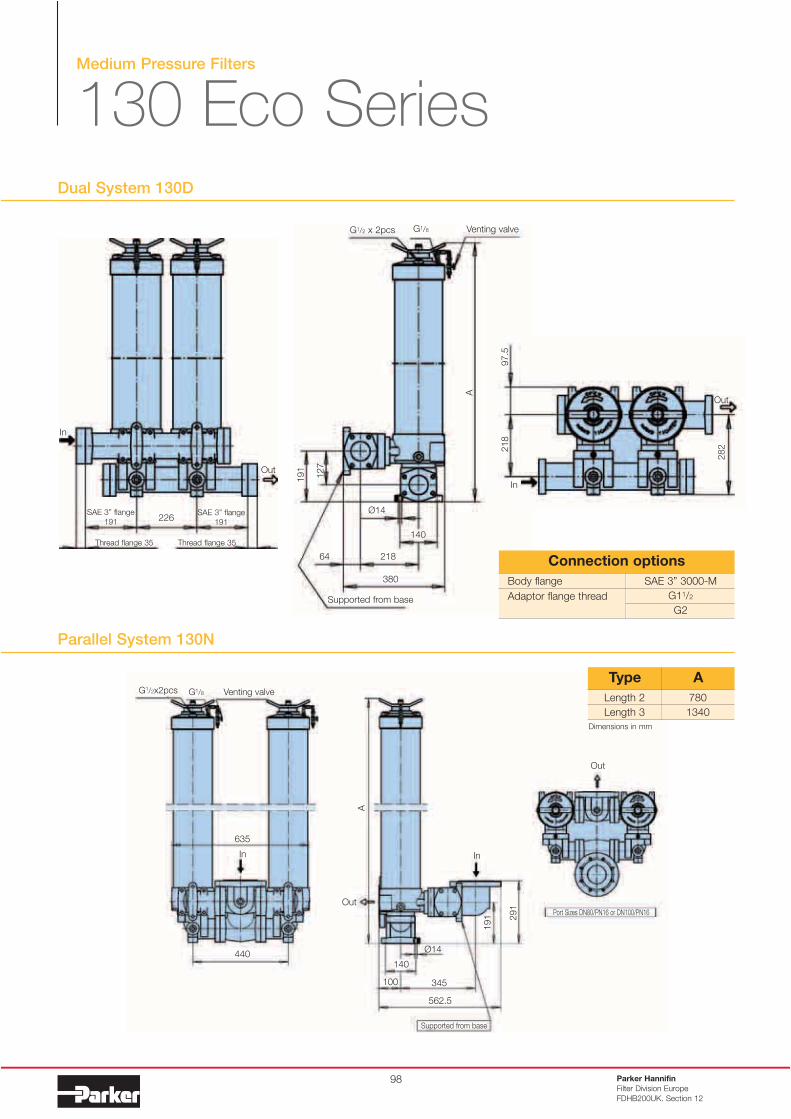
130 Eco SeriesDual System 130D
Parker HannifinFilter Division EuropeFDHB200UK. Section 12
98
In
Out
SAE 3” flange191
SAE 3” flange191
Thread flange 35 Thread flange 35
22697
.521
8
In
Out
282
635
440
In In
Out
Out
291
191
100
140
Ø14
345
562.5
Supported from base
G1/2x2pcs G1/8 Venting valve
A
Port Sizes DN80/PN16 or DN100/PN16
Parallel System 130N
Length 2Length 3
7801340
Type A
SAE 3” 3000-MG11/2
G2
Body flangeAdaptor flange thread
Connection options
G1/2 x 2pcs G1/8 Venting valve
A
191
127
64 218
140
380
Ø14
Supported from base
Dimensions in mm
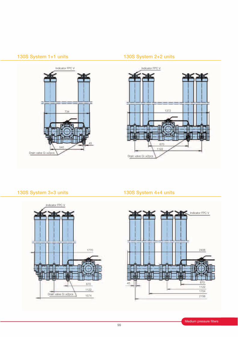
130S System 2+2 units
Medium pressure filters
130S System 1+1 units
99
Indicator FPC V
Drain valve G1/2x2pcs
54045
734
Indicator FPC V
Drain valve G1/2x2pcs
1372
670
1122
Indicator FPC V
Drain valve G1/2x2pcs
1122
670
1574
1770
Indicator FPC V
2406
670
1122
1704
2156
45
130S System 3+3 units 130S System 4+4 units

Medium Pressure Filters
130 Eco SeriesValve Assembly Connection - T-Model
Parker HannifinFilter Division EuropeFDHB200UK. Section 12
100
G1/2x2pcs G1/8 Venting valve
191
InOut
A
140
178
493/503
393/403
Ø14
Indicator port
Valve supported from base Port sizes DN80/PN16 or DN100/PN16
In
Out Slow fill valve
Length 2Length 3
7801340
Type A
Valve supported from base
Valve supported from base
Indicator port
In
Out
A
G1/2x2pcs G1/8 Venting valve
191 36
6/37
6
140
178
Ø14
100 218
462/513
G1/2x2pcs G1/8 Venting valve
A
In
Out
191
Ø14
293/303
393/403
491/501
140
L-Model C-Model
Handle turns counterclockwise
254
Dimensions in mm
Medium pressure filters
Pressure Drop Curves
101
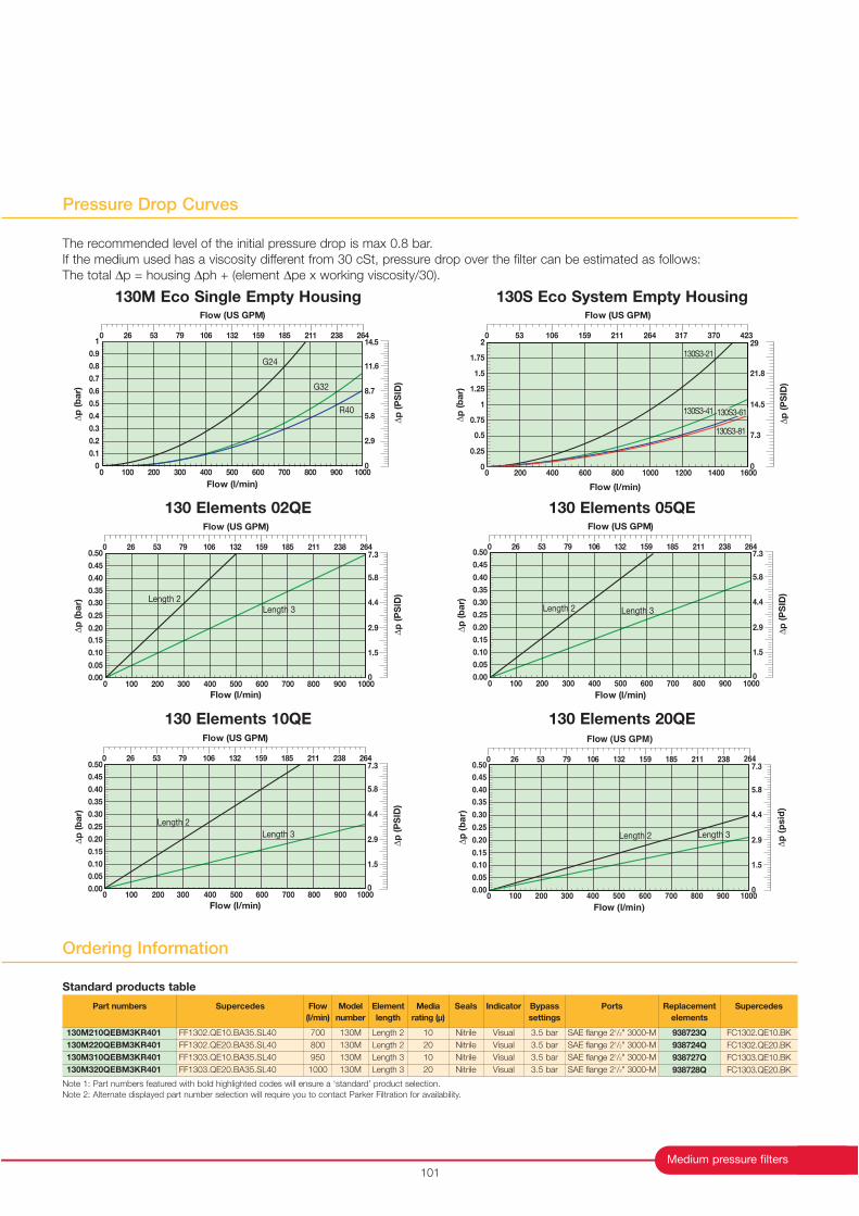
The recommended level of the initial pressure drop is max 0.8 bar.If the medium used has a viscosity different from 30 cSt, pressure drop over the filter can be estimated as follows:The total Δp = housing Δph + (element Δpe x working viscosity/30).
G32
R40
G24
0
0.1
0.2
0.3
0.4
0.5
0.6
0.7
0.8
0.9
1
0 100 200 600 700 1000300 500 900
Δp (b
ar)
Flow (l/min)400 800
Flow (US GPM)
0 26 53 159 185 26479 132 238106 211
Δp (P
SID
)
0
2.9
5.8
8.7
11.6
14.5
Flow (l/min)
Δp (b
ar)
130S3-21
130S3-41
130S3-81
130S3-61
0 200 400 600 800 1000 1200 1400 16000
0.25
0.5
0.75
1
1.25
1.5
1.75
2
Δp (P
SID
)
0
7.3
14.5
21.8
29
Flow (US GPM)
0 53 106 159 211 264 317 370 423
Flow (l/min)
Length 2Length 3
0 100 200 300 400 500 600 700 800 900 10000.000.05
0.10
0.150.20
0.25
0.300.35
0.40
0.45
0.50
Δp (b
ar)
Flow (US GPM)
0 26 53 159 185 26479 132 238106 211
Δp (P
SID
)
0
1.5
2.9
4.4
5.8
7.3
Length 2 Length 3
Flow (l/min)0 100 200 300 400 500 600 700 800 900 1000
0.00
0.05
0.10
0.15
0.20
0.25
0.30
0.35
0.40
0.45
0.50
Δp (b
ar)
Flow (US GPM)
0 26 53 159 185 26479 132 238106 211
Δp (P
SID
)
0
1.5
2.9
4.4
5.8
7.3
Δp (b
ar)
Flow (l/min)
Length 2Length 3
0 100 200 300 400 500 600 700 800 900 10000.00
0.050.10
0.15
0.20
0.25
0.30
0.35
0.40
0.450.50
Flow (US GPM)
0 26 53 159 185 26479 132 238106 211
Δp (P
SID
)
0
1.5
2.9
4.4
5.8
7.3
Flow (l/min)
Length 2 Length 3
0 100 200 300 400 500 600 700 800 900 10000.00
0.05
0.100.15
0.20
0.25
0.30
0.350.40
0.450.50
Δp (
bar
)
Flow (US GPM)
0 26 53 159 185 26479 132 238106 211
Δp (
psi
d)
0
1.5
2.9
4.4
5.8
7.3
130M Eco Single Empty Housing 130S Eco System Empty Housing
130 Elements 05QE
130 Elements 20QE
130 Elements 02QE
130 Elements 10QE
Ordering Information
Note 1: Part numbers featured with bold highlighted codes will ensure a ‘standard’ product selection.Note 2: Alternate displayed part number selection will require you to contact Parker Filtration for availability.
Part numbers
130M210QEBM3KR401130M220QEBM3KR401130M310QEBM3KR401130M320QEBM3KR401
Supercedes
FF1302.QE10.BA35.SL40FF1302.QE20.BA35.SL40FF1303.QE10.BA35.SL40FF1303.QE20.BA35.SL40
Flow(l/min)
700800950
1000
Modelnumber
130M130M130M130M
Elementlength
Length 2Length 2Length 3Length 3
Mediarating (μ)
10201020
Seals
NitrileNitrileNitrileNitrile
Indicator
VisualVisualVisualVisual
Bypasssettings
3.5 bar3.5 bar3.5 bar3.5 bar
Replacementelements
938723Q938724Q938727Q938728Q
Supercedes
FC1302.QE10.BKFC1302.QE20.BKFC1303.QE10.BKFC1303.QE20.BK
Ports
SAE flange 21/2" 3000-MSAE flange 21/2" 3000-MSAE flange 21/2" 3000-MSAE flange 21/2" 3000-M
Standard products table
Parker HannifinFilter Division EuropeFDHB200UK. Section 12
102
Medium Pressure Filters
130 Eco SeriesOrdering Information (cont.)
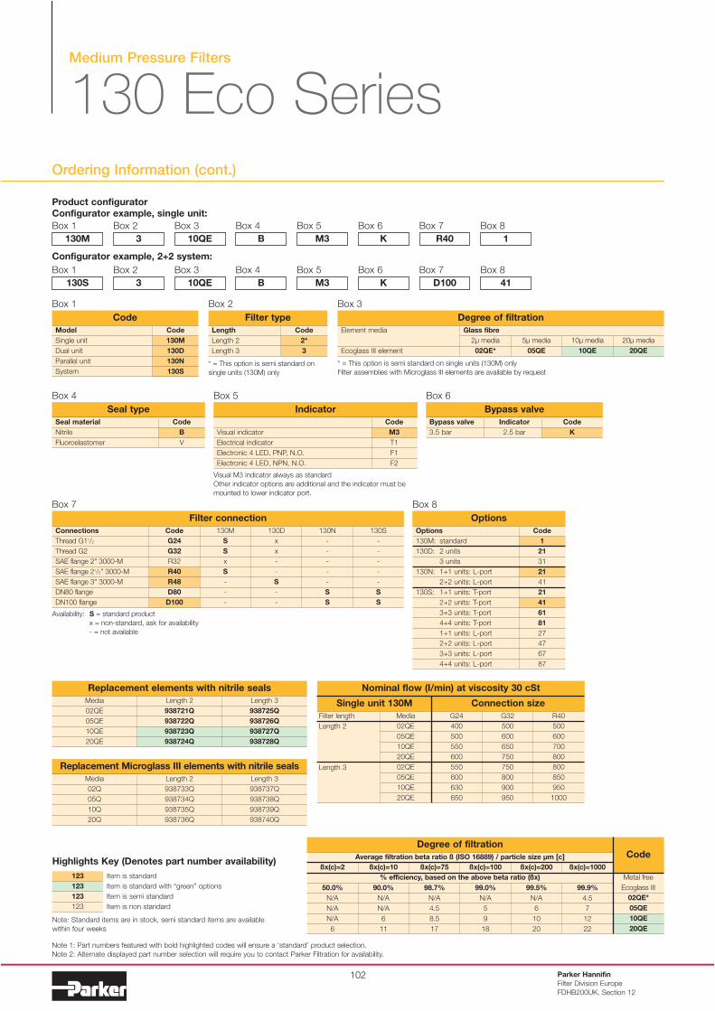
Product configuratorConfigurator example, single unit:Box 1
Code2*3
LengthLength 2Length 3
Filter typeBox 2
130MBox 2
3Box 3
10QEBox 4
BBox 5
M3Box 6
KBox 7
R40Box 8
1
Configurator example, 2+2 system:Box 1
130SBox 2
3Box 3
10QEBox 4
BBox 5
M3Box 6
KBox 7
D100Box 8
41
Note 1: Part numbers featured with bold highlighted codes will ensure a ‘standard’ product selection.Note 2: Alternate displayed part number selection will require you to contact Parker Filtration for availability.
CodeBV
Seal materialNitrileFluoroelastomer
Seal typeBox 4
Bypass valve3.5 bar
Bypass valveIndicator
2.5 barCode
K
Box 6
CodeM3T1F1F2
Visual indicatorElectrical indicatorElectronic 4 LED, PNP, N.O.Electronic 4 LED, NPN, N.O.
IndicatorBox 5
CodeG24G32R32R40R48D80
D100
ConnectionsThread G11/2
Thread G2SAE flange 2" 3000-MSAE flange 21/2" 3000-MSAE flange 3" 3000-MDN80 flangeDN100 flange
Filter connection130M
SSxS---
130Dxx--S--
130N-----SS
130S-----SS
Box 7
Code1213121412141618127476787
Options130M: standard130D: 2 units
3 units130N: 1+1 units: L-port
2+2 units: L-port130S: 1+1 units: T-port
2+2 units: T-port3+3 units: T-port4+4 units: T-port1+1 units: L-port2+2 units: L-port3+3 units: L-port4+4 units: L-port
OptionsBox 8
Code130M130D130N130S
ModelSingle unitDual unitParallel unitSystem
CodeBox 1
Availability: S = standard productx = non-standard, ask for availability- = not available
Media02QE05QE10QE20QE
Replacement elements with nitrile sealsLength 2938721Q938722Q938723Q938724Q
Length 3938725Q938726Q938727Q938728Q
Media02Q05Q10Q20Q
Replacement Microglass III elements with nitrile sealsLength 2938733Q938734Q938735Q938736Q
Length 3938737Q938738Q938739Q938740Q
Filter lengthLength 2
Length 3
Connection sizeSingle unit 130M
Nominal flow (I/min) at viscosity 30 cSt
Media02QE05QE10QE20QE02QE05QE10QE20QE
G24400500550600550600630650
G32500600650750750800900950
R40500600700800800850950
1000
* = This option is semi standard onsingle units (130M) only
Visual M3 indicator always as standardOther indicator options are additional and the indicator must bemounted to lower indicator port.
Item is standardItem is standard with “green” optionsItem is semi standardItem is non standard
123123123123
Highlights Key (Denotes part number availability)
Note: Standard items are in stock, semi standard items are availablewithin four weeks
* = This option is semi standard on single units (130M) onlyFilter assemblies with Microglass III elements are available by request
Box 3
Element media
Ecoglass III element20μ media
20QE10μ media
10QE5μ media
05QE2μ media02QE*
Glass fibre
Degree of filtration
Average filtration beta ratio ß (ISO 16889) / particle size μm [c]
% efficiency, based on the above beta ratio (ßx)ßx(c)=2
50.0%N/AN/AN/A6
Degree of filtrationCode
ßx(c)=10
90.0%N/AN/A611
ßx(c)=75
98.7%N/A4.58.517
ßx(c)=100
99.0%N/A5918
ßx(c)=200
99.5%N/A61020
ßx(c)=1000
99.9%4.571222
02QE*05QE10QE20QE
Metal freeEcoglass III