Embed Size (px)
Citation preview
MedioTM L40 User's Guide Revision 1.7
April 2011
Medio L40 - User's Guide
April 2011 Revision 1.7 2/53
Publishing Information Disclaimer and Limitation of Liability All information herein is either public information or is the property of and owned solely by TAGSYS who shall have and keep the sole right to file patent applications or any other kind of intellectual property protection in connection with such information.
Nothing herein shall be construed as implying or granting to you any rights, by license, grant or otherwise, under any intellectual and/or industrial property rights of or concerning any of TAGSYS’ information.
This document can be used for informational, non-commercial, internal and personal use only provided that:
� The copyright notice below, the confidentiality and proprietary legend and this full warning notice appear in all copies.
� This document shall not be posted on any network computer or broadcast in any media and no modification of any part of this document shall be made.
Use for any other purpose is expressly prohibited and may result in severe civil and criminal liabilities.
The information contained in this document is provided “AS IS” without any warranty of any kind. Unless otherwise expressly agreed in writing, TAGSYS makes no warranty as to the value or accuracy of information contained herein. The document could include technical inaccuracies or typographical errors. Changes are periodically added to the information herein. Furthermore, TAGSYS reserves the right to make any change or improvement in the specifications data, information, and the like described herein, at any time.
Therefore TAGSYS assumes no liability and is not responsible for customer applications or product or software which includes TAGSYS products.
TAGSYS HEREBY DISCLAIMS ALL WARRANTIES AND CONDITIONS WITH REGARD TO THE INFORMATION CONTAINED HEREIN, INCLUDING ALL IMPLIED WARRANTIES OF MERCHANTABILITY, FITNESS FOR A PARTICULAR PURPOSE, TITLE AND NON-INFRINGEMENT. IN NO EVENT SHALL TAGSYS BE LIABLE, WHETHER IN CONTRACT, TORT OR OTHERWISE, FOR ANY INDIRECT, SPECIAL OR CONSEQUENTIAL DAMAGES OR ANY DAMAGES WHATSOEVER INCLUDING BUT NOT LIMITED TO DAMAGES RESULTING FROM LOSS OF USE, DATA, PROFITS, REVENUES, OR CUSTOMERS, ARISING OUT OF OR IN CONNECTION WITH THE USE OR PERFORMANCE OF INFORMATION CONTAINED IN THIS DOCUMENT.
TAGSYS does not and shall not warrant that this product/system/equipment will be resistant to all possible attacks, and shall not incur, and disclaims, any liability in this respect. Even if each product is compliant with current security standards in force on the date of their design, security mechanisms' resistance necessarily evolves according to the state-of-the-art in security and notably under the emergence of new attacks. Under no circumstances shall TAGSYS be held liable for any third party actions, and in particular in case of any successful attack against systems or equipment incorporating TAGSYS products.
TAGSYS disclaims any liability with respect to security for direct, indirect, incidental or consequential damages that result from any use of its products. It is further stressed that independent testing and verification by the person using the product is particularly encouraged, especially in any application in which defective, incorrect, or insecure functioning could result in damage to persons or property, denial of service, or loss of privacy.
© 2000-2011 TAGSYS. All rights reserved.
Microsoft, Visual C++, Windows, and Windows NT are either registered trademarks or trademarks of Microsoft Corporation in the U.S.A. and/or other countries.
I-Code is a registered trademark of Philips.
TAGSYS, MEDIO, E-connectware are registered trademarks of TAGSYS
Printed in France.
TAGSYS – 785 Voie Antiope, Athélia III, 13600 La Ciotat, France.
Tel: +33 (0) 4.42.18.89.00 / Fax: +33 (0) 4.42.18.89.01
Document Reference: DOC14467A7.
Medio L40 - User's Guide
April 2011 Revision 1.7 3/53
Read This First Welcome to the TAGSYS range of products operating at the 13.56 MHz frequency. This range of products is used to implement high-quality RFID systems for demanding applications.
This document provides information about how to install and use the Medio L40 reader.
Audience
This document requires familiarity with RFID technology. It is intended for people in charge of installing and using the product.
Conventions
Symbol Meaning
CAUTION: A note that advises users that a specific action could result in the loss of data or damage the hardware. WARNING: A note that advises users that a specific action may result in physical harm.
A note that provides additional information that helps the user performs a task or obtains the best performance from the product.
If you need assistance Please contact your nearest TAGSYS sales representative or the TAGSYS welcome desk at:
Telephone: +33 (0) 4 42 18 89 00
Fax: +33 (0) 4 42 18 89 01
E-Mail: [email protected]
Website: http://www.tagsysrfid.com
Contact for Comments
We welcome your feedback to help us provide high quality documentation.
For technical comments, please contact our welcome desk:
Telephone: +33 (0) 4 42 18 89 00
Fax: +33 (0) 4 42 18 89 01
E-Mail: [email protected]
Please remember to quote the Document Reference Number DOC14467A7, your job title and your company.
Medio L40 - User's Guide
4/53 Revision 1.7 April 2011
Quality Issues TAGSYS implements stringent quality controls at all stages of its manufacturing process. However, should you find a defect with this product, please notify your TAGSYS Quality Service representative using the dedicated Product Return Form.
Telephone: +33 (0) 4 42 18 89 36
Fax: +33 (0) 4 42 18 89 01
Medio L40 - User's Guide
April 2011 Revision 1.7 5/53
Table of Contents
PUBLISHING INFORMATION __________________________________________________________ 2
DISCLAIMER AND LIMITATION OF LIABILITY___________________________________________________ 2
READ THIS FIRST ____________________________________________________________________ 3
AUDIENCE_____________________________________________________________________________ 3 CONVENTIONS _________________________________________________________________________ 3 IF YOU NEED ASSISTANCE ________________________________________________________________ 3 CONTACT FOR COMMENTS _______________________________________________________________ 3 QUALITY ISSUES _______________________________________________________________________ 4
1 FOR YOUR SAFETY _______________________________________________________________ 7
1.1 GENERAL USE ____________________________________________________________________ 7 1.2 CARE AND MAINTENANCE ___________________________________________________________ 7 1.3 IMPORTANT SAFETY INFORMATION ____________________________________________________ 8 1.3.1 OPERATING ENVIRONMENT ________________________________________________________ 8
2 CERTIFICATION___________________________________________________________________ 9
2.1 OCCUPATIONAL HEALTH AND SAFETY NOTICES _________________________________________ 9 2.2 REGULATORY NOTICES _____________________________________________________________ 9 2.2.1 IN EUROPE (CE AND RTTE DIRECTIVES) _____________________________________________ 9 2.2.2 FCC ID CROSS REFERENCE TABLE _________________________________________________ 9 2.2.3 IN USA (FCC DIRECTIVE)_________________________________________________________ 13 2.2.4 IN CANADA _____________________________________________________________________ 14 2.3 ROHS AND WEEE DIRECTIVES _____________________________________________________ 14 2.3.1 ROHS (RESTRICTION OF THE USES OF CERTAIN HAZARDOUS SUBSTANCES) _______________ 14 2.3.2 WEEE (WASTE ELECTRICAL AND ELECTRONIC EQUIPMENT) ____________________________ 15
3 OVERVIEW ______________________________________________________________________ 16
3.1 KEY FEATURES___________________________________________________________________ 17 3.2 DELIVERY _______________________________________________________________________ 18 3.3 PHYSICAL DESCRIPTION ___________________________________________________________ 18 3.3.1 FRONT PANEL __________________________________________________________________ 18 3.3.2 REAR PANEL ___________________________________________________________________ 19
4 INSTALLATION __________________________________________________________________ 20
4.1 MECHANICAL ASPECTS ____________________________________________________________ 20 4.2 CABLING REQUIREMENTS __________________________________________________________ 20 4.3 USING USB INTERFACE ____________________________________________________________ 21 4.3.1 INSTALLING USB DRIVERS ________________________________________________________ 21 4.3.2 USING THE USB INTERFACE_______________________________________________________ 21 4.4 USING RS-232 INTERFACE _________________________________________________________ 22 4.5 USING 10/100 ETHERNET INTERFACE ________________________________________________ 22 4.6 RESTORING FACTORY CONFIGURATION _______________________________________________ 23
Medio L40 - User's Guide
6/53 Revision 1.7 April 2011
4.7 RUNNING TAGSYS EXPLORER FOR THE FIRST TIME _____________________________________ 23 4.7.1 INSTALLING TAGSYS EXPLORER____________________________________________________ 23 4.7.2 CONNECTING TO A DEVICE USING TAGSYS EXPLORER WIZARD __________________________ 25 4.7.3 READING THE UID OF ISO 15693 TAGS _____________________________________________ 30 4.7.4 READING AND WRITING ISO 15693 TAG MEMORY _____________________________________ 31 4.7.5 UPGRADING SYSTEM OR RADIO FIRMWARE __________________________________________ 32
5 ADVANCED NOTIONS ____________________________________________________________ 35
5.1 READER ARCHITECTURE ___________________________________________________________ 35 5.2 READER TO HOST PROTOCOLS______________________________________________________ 36 5.2.1 TAGSYS STXNG _______________________________________________________________ 36 5.2.2 HEARTBEAT ____________________________________________________________________ 36 5.2.3 TELNET________________________________________________________________________ 37 5.2.4 SERIAL CONSOLE________________________________________________________________ 37 5.2.5 STANDALONE MODE _____________________________________________________________ 37 5.3 READER OPERATION PRINCIPLES ____________________________________________________ 38 5.3.1 NOTION OF READ MODES _________________________________________________________ 38 5.3.2 NOTION OF EVENTS ______________________________________________________________ 39
6 TECHNICAL SPECIFICATIONS ____________________________________________________ 40
6.1 TECHNICAL DATA _________________________________________________________________ 40 6.2 RS232 INTERFACE________________________________________________________________ 41 6.3 GPIO CONNECTOR _______________________________________________________________ 42 6.3.1 PIN ASSIGNMENT________________________________________________________________ 42 6.3.2 ELECTRICAL CHARACTERISTICS____________________________________________________ 42 6.3.3 USING INPUTS __________________________________________________________________ 42 6.3.4 USING OUTPUTS ________________________________________________________________ 44
7 ELECTRICAL CHARACTERISTICS _________________________________________________ 45
7.1 ABSOLUTE MAXIMUM RATINGS ______________________________________________________ 45 7.2 POWER SUPPLY DC CHARACTERISTICS AND START-UP __________________________________ 46 7.3 RS232 COMMUNICATION PORT CHARACTERISTICS _____________________________________ 47 7.4 USB COMMUNICATION PORT CHARACTERISTICS _______________________________________ 48 7.5 ANTENNA ELECTRICAL CHARACTERISTICS_____________________________________________ 48 7.6 INPUT / OUTPUT ELECTRICAL CHARACTERISTICS _______________________________________ 49
8 MECHANICAL CHARACTERISTICS ________________________________________________ 50
8.1 DIMENSIONS AND GENERAL MECHANICAL INFORMATION _________________________________ 50 8.2 FIXING THE PRODUCT______________________________________________________________ 50
9 WARRANTY CONDITIONS ________________________________________________________ 51
9.1 WARRANTY ______________________________________________________________________ 51 9.2 WARRANTY EXCLUSIONS___________________________________________________________ 51 9.2.1 GENERAL PROVISIONS ___________________________________________________________ 52 9.2.2 HOW TO RETURN DEFECTIVE PRODUCTS ____________________________________________ 52
Medio L40 - User's Guide
April 2011 Revision 1.7 7/53
1 For Your Safety 1.1 General Use
The Medio L40 reader is designed to be reliable and to provide continuous, trouble-free service. Please observe the following general tips:
� Take care not to scratch the device. Keep the device clean. When working with the device, use only TAGSYS-approved accessories.
� This device is not waterproof and should not be exposed to rain or moisture. Under extreme conditions, water may enter the circuitry.
� Protect the device from extreme temperatures. For example, do not place the device in a windowed area where the sun may cause extreme temperatures, and keep it away from heaters and other heat sources.
� Do not store or use the device in any location that is extremely dusty, damp, or wet.
� Use a soft, damp cloth to clean the device. If the surface of the device becomes soiled, clean it with a soft cloth moistened with a diluted window-cleaning solution.
1.2 Care and Maintenance
This device should be handled with care. The suggestions below will increase the lifetime of this device.
• Keep the device and all parts and accessories out of the reach of small children.
• Keep the device dry. Precipitation, humidity and liquids contain minerals that will corrode electronic circuits.
• Do not use or store the device in dusty, dirty areas. Its moving parts can be damaged.
• Do not store in hot areas. High temperatures can shorten the life of electronic devices, damage batteries and warp or melt certain plastics.
• Do not store in cold areas. When the device warms up (to its normal temperature), moisture can form inside the device, which may damage electronic circuit boards.
• Do not attempt to open the device. Non-professional handling of the device may damage it and will void the TAGSYS warranty.
• Handle the device with care. Shock and vibration may break internal circuit boards.
• Do not clean the device with harsh chemicals, cleaning solvents or strong detergents. Gently wipe the device with a soft cloth slightly dampened in a mild soap-and-water solution.
• Do not paint the device. Paint may clog the device’s moving parts and prevent proper operation. Paint with metallic contents may limit device performances.
• If the device or any accessory are not working properly, take it to your nearest qualified TAGSYS representative.

Medio L40 - User's Guide
8/53 Revision 1.7 April 2011
1.3 Important Safety Information
1.3.1 Operating Environment When connecting the device or any accessory to another device, read its user’s guide for detailed safety instructions. Do not connect incompatible products.
As with all RF equipment, users are advised that the equipment should only be used in its normal operating mode described in this document.
Medio L40 - User's Guide
April 2011 Revision 1.7 9/53
2 Certification 2.1 Occupational Health and Safety Notices
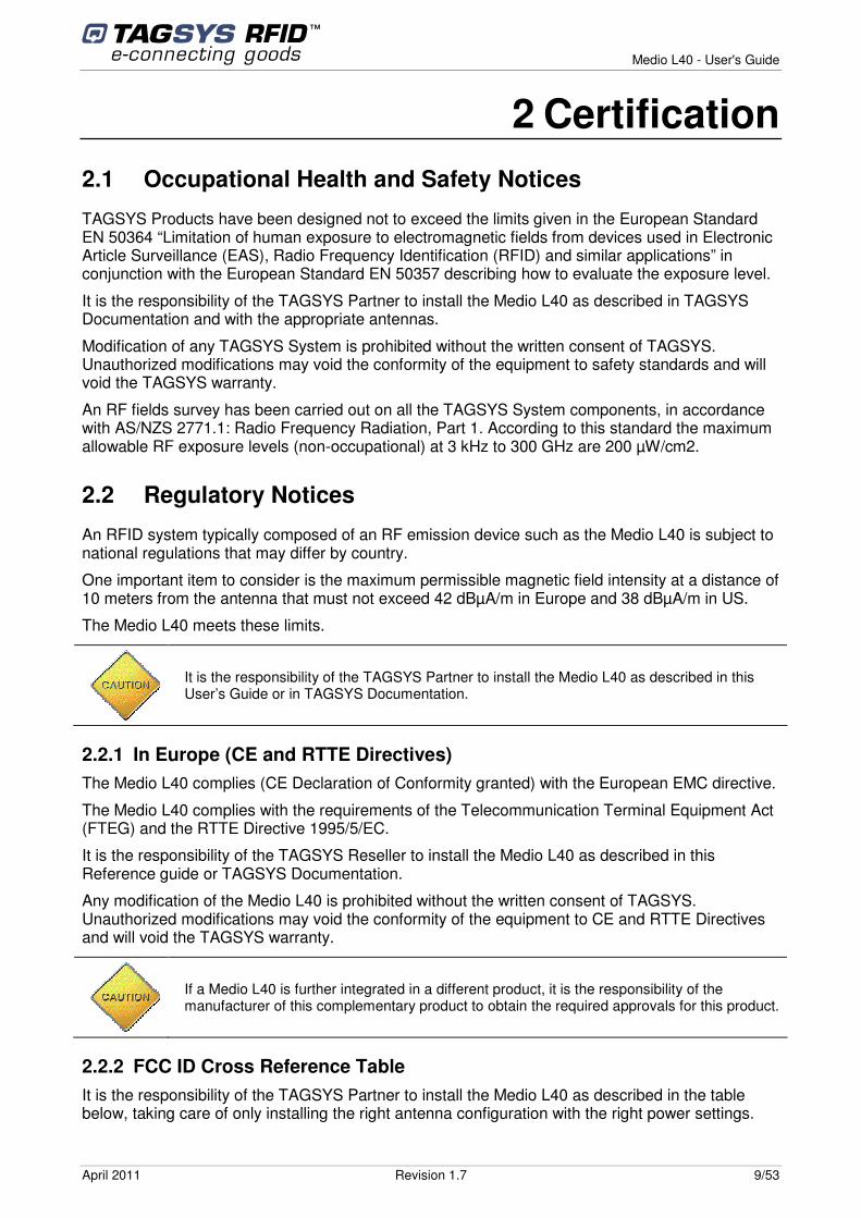
TAGSYS Products have been designed not to exceed the limits given in the European Standard EN 50364 “Limitation of human exposure to electromagnetic fields from devices used in Electronic Article Surveillance (EAS), Radio Frequency Identification (RFID) and similar applications” in conjunction with the European Standard EN 50357 describing how to evaluate the exposure level.
It is the responsibility of the TAGSYS Partner to install the Medio L40 as described in TAGSYS Documentation and with the appropriate antennas.
Modification of any TAGSYS System is prohibited without the written consent of TAGSYS. Unauthorized modifications may void the conformity of the equipment to safety standards and will void the TAGSYS warranty.
An RF fields survey has been carried out on all the TAGSYS System components, in accordance with AS/NZS 2771.1: Radio Frequency Radiation, Part 1. According to this standard the maximum allowable RF exposure levels (non-occupational) at 3 kHz to 300 GHz are 200 µW/cm2.
2.2 Regulatory Notices
An RFID system typically composed of an RF emission device such as the Medio L40 is subject to national regulations that may differ by country.
One important item to consider is the maximum permissible magnetic field intensity at a distance of 10 meters from the antenna that must not exceed 42 dBµA/m in Europe and 38 dBµA/m in US.
The Medio L40 meets these limits.
2.2.1 In Europe (CE and RTTE Directives) The Medio L40 complies (CE Declaration of Conformity granted) with the European EMC directive.
The Medio L40 complies with the requirements of the Telecommunication Terminal Equipment Act (FTEG) and the RTTE Directive 1995/5/EC.
It is the responsibility of the TAGSYS Reseller to install the Medio L40 as described in this Reference guide or TAGSYS Documentation.
Any modification of the Medio L40 is prohibited without the written consent of TAGSYS. Unauthorized modifications may void the conformity of the equipment to CE and RTTE Directives and will void the TAGSYS warranty.
2.2.2 FCC ID Cross Reference Table It is the responsibility of the TAGSYS Partner to install the Medio L40 as described in the table below, taking care of only installing the right antenna configuration with the right power settings.
It is the responsibility of the TAGSYS Partner to install the Medio L40 as described in this User’s Guide or in TAGSYS Documentation.
If a Medio L40 is further integrated in a different product, it is the responsibility of the manufacturer of this complementary product to obtain the required approvals for this product.
Medio L40 - User's Guide
10/53 Revision 1.7 April 2011
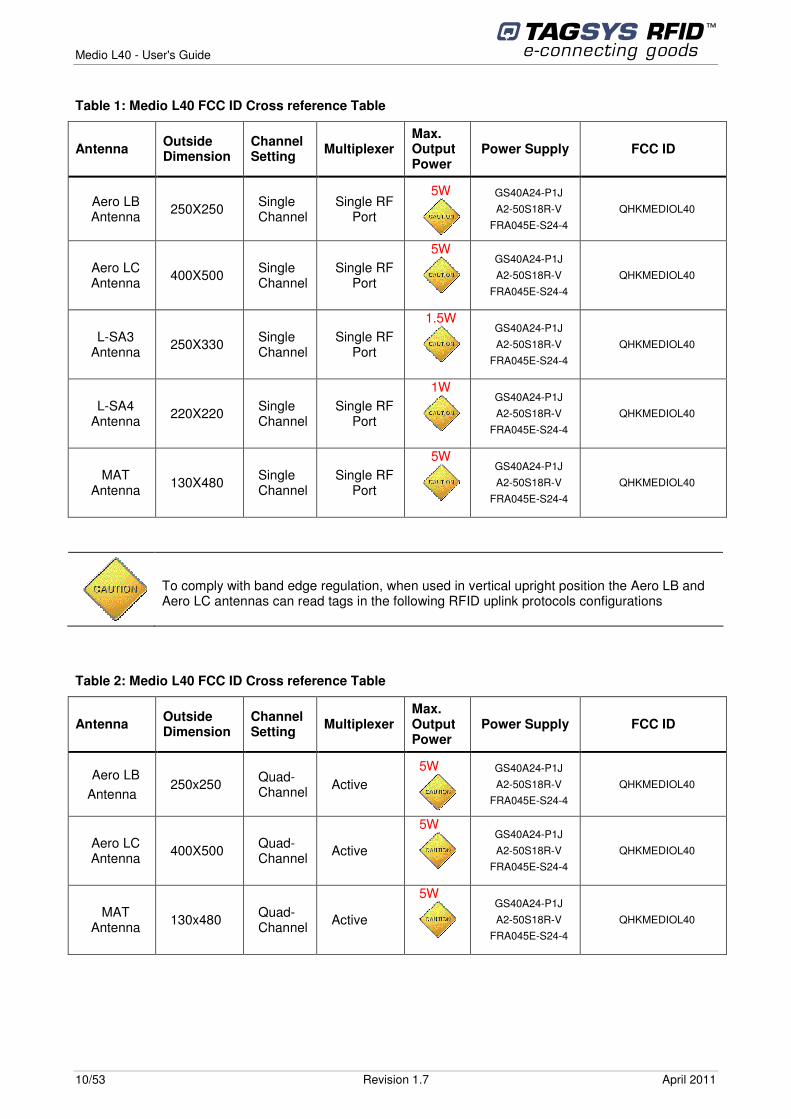
Table 1: Medio L40 FCC ID Cross reference Table
Antenna Outside Dimension
Channel Setting Multiplexer
Max. Output Power
Power Supply FCC ID
Aero LB Antenna 250X250 Single
Channel Single RF
Port
5W
GS40A24-P1J A2-50S18R-V
FRA045E-S24-4 QHKMEDIOL40
Aero LC Antenna 400X500 Single
Channel Single RF
Port
5W
GS40A24-P1J A2-50S18R-V
FRA045E-S24-4 QHKMEDIOL40
L-SA3 Antenna 250X330 Single
Channel Single RF
Port
1.5W
GS40A24-P1J A2-50S18R-V
FRA045E-S24-4 QHKMEDIOL40
L-SA4 Antenna 220X220 Single
Channel Single RF
Port
1W
GS40A24-P1J A2-50S18R-V
FRA045E-S24-4 QHKMEDIOL40
MAT Antenna 130X480 Single
Channel Single RF
Port
5W
GS40A24-P1J A2-50S18R-V
FRA045E-S24-4 QHKMEDIOL40
Table 2: Medio L40 FCC ID Cross reference Table
Antenna Outside Dimension
Channel Setting Multiplexer
Max. Output Power
Power Supply FCC ID
Aero LB Antenna
250x250 Quad-Channel Active
5W
GS40A24-P1J A2-50S18R-V
FRA045E-S24-4 QHKMEDIOL40
Aero LC Antenna 400X500 Quad-
Channel Active
5W
GS40A24-P1J A2-50S18R-V
FRA045E-S24-4 QHKMEDIOL40
MAT Antenna 130x480 Quad-
Channel Active
5W
GS40A24-P1J A2-50S18R-V
FRA045E-S24-4 QHKMEDIOL40
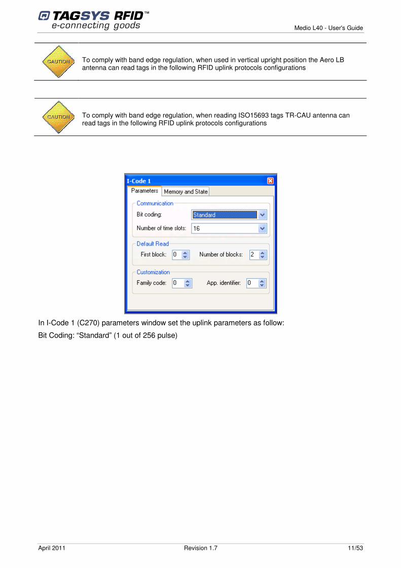
To comply with band edge regulation, when used in vertical upright position the Aero LB and Aero LC antennas can read tags in the following RFID uplink protocols configurations
Medio L40 - User's Guide
April 2011 Revision 1.7 11/53
In I-Code 1 (C270) parameters window set the uplink parameters as follow:
Bit Coding: “Standard” (1 out of 256 pulse)
To comply with band edge regulation, when used in vertical upright position the Aero LB antenna can read tags in the following RFID uplink protocols configurations
To comply with band edge regulation, when reading ISO15693 tags TR-CAU antenna can read tags in the following RFID uplink protocols configurations
Medio L40 - User's Guide
12/53 Revision 1.7 April 2011
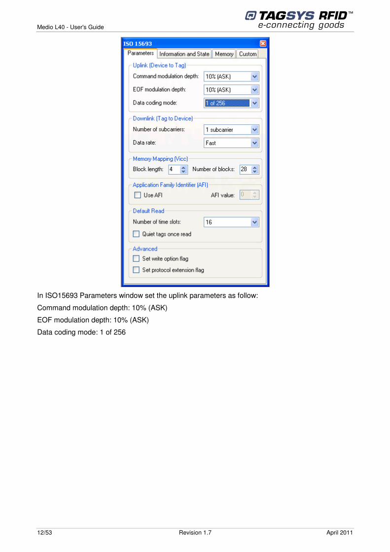
In ISO15693 Parameters window set the uplink parameters as follow:
Command modulation depth: 10% (ASK)
EOF modulation depth: 10% (ASK)
Data coding mode: 1 of 256
Medio L40 - User's Guide
April 2011 Revision 1.7 13/53
2.2.3 In USA (FCC Directive) The Medio L40 has been designed to comply with Part 15 of the FCC Rules. Furthermore typical configurations listed section 2.2.2 FCC ID Cross Reference Table have been successfully tested with Part 15 of the FCC rules (FCC ID Numbers are listed on all system-mounted TAGSYS Antennas).
Medio L40 WARNING TO USERS IN THE UNITED STATES
FEDERAL COMMUNCIATIONS COMMISSION (FCC) RADIO
INTERFERENCE STATEMENT 47 CFR Section 15.105(b)
This equipment has been tested and found to comply with the limits for a Class B digital device, pursuant to Part 15 of the FCC Rules. These limits are designed to provide reasonable protection against harmful interference in a residential installation. This equipment generates, uses and can radiate radio frequency energy and if not installed and used in accordance with the instructions may cause harmful interference to radio communications. However, there is no guarantee that interference will not occur in a particular installation. If this equipment does cause harmful interference to radio or television reception, which can be determined by turning the equipment off and on, the user is encouraged to try to correct the interference by one or more of the following measures:
� Reorient or relocate the receiving antenna.
� Increase the separation between the equipment and receiver.
� Connect the equipment into an outlet on a circuit different to that to which the receiver is connected.
� Consult the dealer or an experienced radio/TV technician for help.
NO UNAUTHORIZED MODIFICATIONS
47 CFR Section 15.21
CAUTION: This equipment may not be modified, altered, or changed in any way without signed written permission from TAGSYS SA. Unauthorized modification may void the equipment authorization from the FCC and will void the TAGSYS warranty.
ANTENNA REQUIREMENT
47 CFR Section 15.203
CAUTION: This equipment must be professionally installed. The installer shall be responsible for ensuring that the proper antenna is employed so that the limits in this part are not exceeded. Non-professional installation or installation of the equipment with an improper antenna may void the equipment authorization from the FCC and will void the TAGSYS warranty.
Operation is subject to the following two conditions: (1) The system devices may not cause harmful interference, and (2) The system devices must accept any interference received, including interference that may cause undesired operation.

Medio L40 - User's Guide
14/53 Revision 1.7 April 2011
2.2.4 In Canada Under Industry Canada regulations, this radio transmitter may only operate using an
antenna of a type and maximum (or lesser) gain approved for the transmitter by Industry Canada. To reduce potential radio interference to other users, the antenna type and its gain should be so chosen that the equivalent isotropically radiated power (e.i.r.p.) is not more than that necessary for successful communication.
Conformément à la réglementation d'Industrie Canada, le présent émetteur radio peut fonctionner avec une antenne d'un type et d'un gain maximal (ou inférieur) approuvé pour l'émetteur par Industrie Canada. Dans le but de réduire les risques de brouillage radioélectrique à l'intention des autres utilisateurs, il faut choisir le type d'antenne et son gain de sorte que la puissance isotrope rayonnée équivalente (p.i.r.e.) ne dépasse pas l'intensité nécessaire à l'établissement d'une communication satisfaisante.
This radio transmitter (IC: 7562A-MEDIOL40) has been approved by Industry Canada to operate with the antenna types listed below with the maximum permissible gain and required antenna impedance for each antenna type indicated. Antenna types not included in this list, having a gain greater than the maximum gain indicated for that type, are strictly prohibited for use with this device.
Le présent émetteur radio (IC: 7562A-MEDIOL40) a été approuvé par Industrie Canada pour fonctionner avec les types d'antenne énumérés ci-dessous et ayant un gain admissible maximal et l'impédance requise pour chaque type d'antenne. Les types d'antenne non inclus dans cette liste, ou dont le gain est supérieur au gain maximal indiqué, sont strictement interdits pour l'exploitation de l'émetteur.
The Medio L40 device has been designed to operate with the antennas listed below, and having a maximum gain of -25 dBi. Antenna not included in this list or having a gain greater than -25 dBi are striclly prohibited for use with this device. The require antenna impedance is 50 ohms.
Aero LB, Aero LC, LSA3, LSA4 and Mat Antenna antennas meet this requirement with a gain less than -25dBi. Le lecteur Medio L40 a été conçu pour fonctionner avec les antennes citées ci-dessous et ayant un gain maixumum de -25dBi. Les antennes non inclus dans cette liste ou ayant un gain supérieur à -25dBi sont strictement interdites pour un usage avec ce lecteur. L’impédance de l’antenne doit être de 50 ohms. Les antennes Aero LB, Aero LC, LSA3, LSA4 et Mat Antenna satisfont à cette exigence avec un gain inférieur à -25dBi.
This device complies with Industry Canada licence-exempt RSS standard(s). Operation is subject to the following two conditions: (1) this device may not cause interference, and (2) this device must accept any interference, including interference that may cause undesired operation of the device.
Le présent appareil est conforme aux CNR d'Industrie Canada applicables aux appareils radio exempts de licence. L'exploitation est autorisée aux deux conditions suivantes : (1) l'appareil ne doit pas produire de brouillage, et (2) l'utilisateur de l'appareil doit accepter tout brouillage radioélectrique subi, même si le brouillage est susceptible d'en compromettre le fonctionnement.
2.3 RoHS and WEEE Directives
2.3.1 RoHS (Restriction of the uses of certain Hazardous Substances) TAGSYS certifies that this product is compliant with the European Directive 2002/95/EC for the restriction in Electric and Electronic Equipments (RoHS) of the use of the following hazardous substances:
• Lead
Medio L40 - User's Guide
April 2011 Revision 1.7 15/53
• Mercury
• Cadmium
• Hexavalent Chromium
• Polybrominated biphenyl flame retardants
• Polybrominated diphenyl ether flame retardants
This declaration is based on information provided by our suppliers and subcontractors.
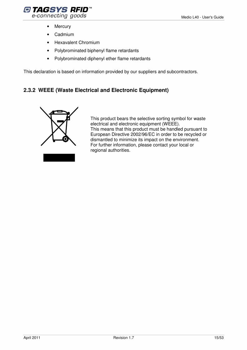
2.3.2 WEEE (Waste Electrical and Electronic Equipment)
This product bears the selective sorting symbol for waste electrical and electronic equipment (WEEE). This means that this product must be handled pursuant to European Directive 2002/96/EC in order to be recycled or dismantled to minimize its impact on the environment. For further information, please contact your local or regional authorities.
Medio L40 - User's Guide
16/53 Revision 1.7 April 2011
3 Overview The Medio L40 is a long-range 13.56MHz RFID reader intended for RFID applications
requiring a high performance, long range RFID infrastructure.
The L40 uses advances in Digital Signal Processing (DSP) and RF Front End technology to achieve breakthrough performance in read range and read speed with industry leading signal to noise ratio. The L40 has been specifically designed to operate in noisy environments such as manufacturing plants and distribution facilities while maintaining the highest levels of data integrity for item level track and trace, inventory management and security. Designed as a network device, the L40 conserves critical network bandwidth by filtering tag data to remove redundancies before transmitting to enterprise systems.
With breakthrough sensor technology and self diagnostic capability, the L40 is the industry’s first self-correcting intelligent RFID reader. The L40 can be remotely managed and administered to ensure you get the highest levels of performance from your RFID infrastructure. The L40 and e-connectware, TAGSYS’ comprehensive set of management and administrative tools, create an intelligent platform to allow you to manage your RFID infrastructure just as you do a voice or data network to enable scalable, secure and persistent RFID Quality of Service.
Medio L40 - User's Guide
April 2011 Revision 1.7 17/53
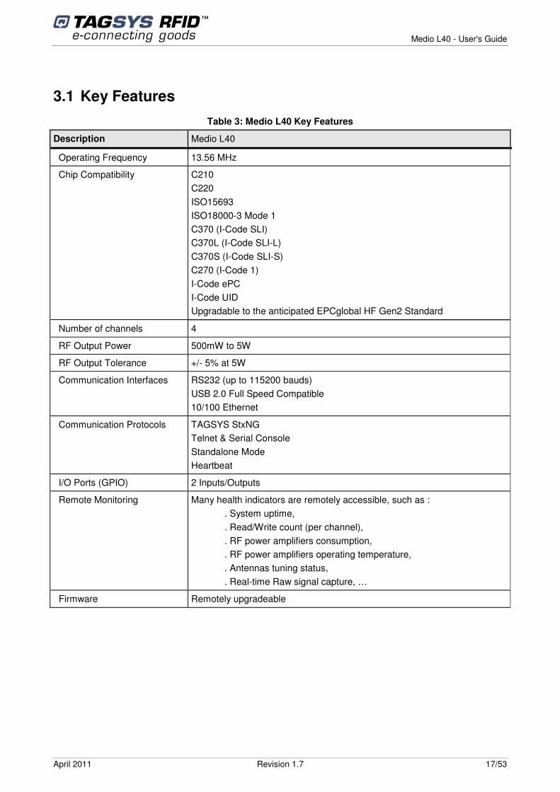
3.1 Key Features Table 3: Medio L40 Key Features
Description Medio L40
Operating Frequency 13.56 MHz
Chip Compatibility C210 C220 ISO15693 ISO18000-3 Mode 1 C370 (I-Code SLI) C370L (I-Code SLI-L) C370S (I-Code SLI-S) C270 (I-Code 1) I-Code ePC I-Code UID Upgradable to the anticipated EPCglobal HF Gen2 Standard
Number of channels 4
RF Output Power 500mW to 5W
RF Output Tolerance +/- 5% at 5W
Communication Interfaces RS232 (up to 115200 bauds) USB 2.0 Full Speed Compatible 10/100 Ethernet
Communication Protocols TAGSYS StxNG Telnet & Serial Console Standalone Mode Heartbeat
I/O Ports (GPIO) 2 Inputs/Outputs
Remote Monitoring Many health indicators are remotely accessible, such as : . System uptime, . Read/Write count (per channel), . RF power amplifiers consumption, . RF power amplifiers operating temperature, . Antennas tuning status, . Real-time Raw signal capture, …
Firmware Remotely upgradeable
Medio L40 - User's Guide
18/53 Revision 1.7 April 2011
3.2 Delivery
The Medio L40 reader kit contains the following items:
Table 4: Package Contents
Quantity Item
1 Medio L40 reader
2 CD-ROMs : • Medio L40 User’s Guide & Medio L400/L40 Designer’s guide • USB Drivers for Windows® 2000, 2003, XP, Vista & Seven • Tagsys Explorer software (reader configuration and upgrade on Windows® 9x,
NT®, 2000, XP, Vista & Seven platforms) • Software development kits (SDKs) including documentation and sample codes
(Win32 Native DLL, .NET component, JAVA archive)
1 Welcome Letter / Product Return Form
3.3 Physical Description
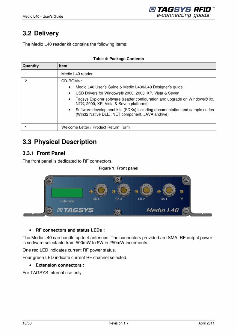
3.3.1 Front Panel The front panel is dedicated to RF connectors.
Figure 1: Front panel
• RF connectors and status LEDs :
The Medio L40 can handle up to 4 antennas. The connectors provided are SMA. RF output power is software selectable from 500mW to 5W in 250mW increments.
One red LED indicates current RF power status.
Four green LED indicate current RF channel selected.
• Extension connectors :
For TAGSYS Internal use only.
Medio L40 - User's Guide
April 2011 Revision 1.7 19/53
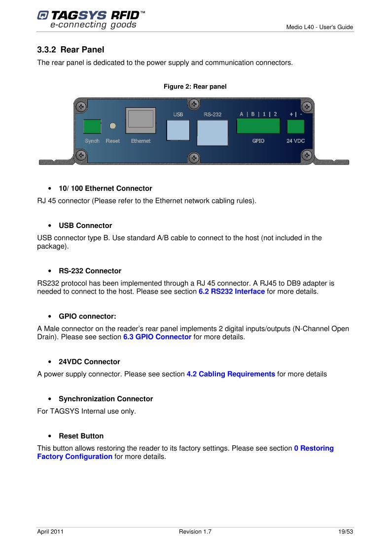
3.3.2 Rear Panel The rear panel is dedicated to the power supply and communication connectors.
Figure 2: Rear panel
• 10/ 100 Ethernet Connector
RJ 45 connector (Please refer to the Ethernet network cabling rules).
• USB Connector
USB connector type B. Use standard A/B cable to connect to the host (not included in the package).
• RS-232 Connector
RS232 protocol has been implemented through a RJ 45 connector. A RJ45 to DB9 adapter is needed to connect to the host. Please see section 6.2 RS232 Interface for more details.
• GPIO connector:
A Male connector on the reader’s rear panel implements 2 digital inputs/outputs (N-Channel Open Drain). Please see section 6.3 GPIO Connector for more details.
• 24VDC Connector
A power supply connector. Please see section 4.2 Cabling Requirements for more details
• Synchronization Connector
For TAGSYS Internal use only.
• Reset Button
This button allows restoring the reader to its factory settings. Please see section 0 Restoring Factory Configuration for more details.
Medio L40 - User's Guide
20/53 Revision 1.7 April 2011
4 Installation This section describes how to install the Medio L40 reader.
4.1 Mechanical Aspects
The Medio L40 is delivered six slots allowing easily fastening off the reader on your system. Please see section Erreur ! Source du renvoi introuvable. Mechanical Data for more details.
4.2 Cabling Requirements
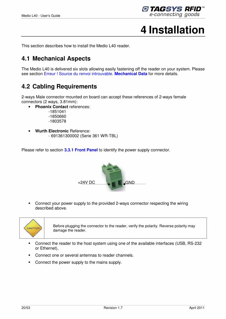
2-ways Male connector mounted on board can accept these references of 2-ways female connectors (2 ways, 3.81mm):
• Phoenix Contact references: -1851041 -1850660 -1803578
• Wurth Electronic Reference: - 691361300002 (Serie 361 WR-TBL)
Please refer to section 3.3.1 Front Panel to identify the power supply connector.
� Connect your power supply to the provided 2-ways connector respecting the wiring described above.
Before plugging the connector to the reader, verify the polarity. Reverse polarity may damage the reader.
� Connect the reader to the host system using one of the available interfaces (USB, RS-232 or Ethernet),
� Connect one or several antennas to reader channels.
� Connect the power supply to the mains supply.
+24V DC GND
Medio L40 - User's Guide
April 2011 Revision 1.7 21/53
For USA and countries under FCC Part 15 regulation only use the Antenna and Power Supply Unit combination tested and specified in the cross reference table of the corresponding Medio L40 (see section 2.2.2 FCC ID Cross Reference Table). The use of any other combination of reader version, antenna type and Power Supply Unit is subject to obtaining a specific FCC ID either by TAGSYS or by its Qualified Partner under TAGSYS supervision. For other countries, only use Power Supply Units GS40A24-P1J or A2-50S118R-V or FRA045E-S24-4. If using any other Power Supply Unit , the selected Power Supply Unit must meet all following criteria:
• UL Listed UL60950 and CB Certified for Information Technology Equipment • Class B Emission CISPR22 EN55022 • CE marked • LPS
4.3 Using USB Interface
4.3.1 Installing USB Drivers At first connection to the PC USB port, Windows® will detect the TAGSYS Medio L40 reader and will ask to install a driver. The USB drivers are located into the USB Drivers folder on the product CD-ROM.
Two drivers will be installed:
- The USB device driver.
- The virtual COM port (VCP) driver. The VCP driver emulates a standard PC COM port.
After installation of the drivers, power up and connect your Medio L40 to a spare USB port on your PC to launch the Windows Found New hardware Wizard
� Select “No, not this time” and click next to proceed with the installation.
� Select “Install from a list or specific location (Advanced)” and then click “Next”.
� Select “Search for the best driver in these locations” and click the Browse button to select the TAGSYS USB Drivers folder on the Product CR-Rom. Then click “Next” to proceed.
� Windows should then display a message indicating that the installation was successful. Click Finish to complete the installation.
Repeat the procedure above when Windows® asks for drivers again (virtual com port).
To confirm that the installation has completed successfully, open the Device Manager and select “View > Devices by type”. The TAGSYS Medio L40 reader now appears as an additional COM port.
4.3.2 Using the USB interface Once the USB drivers are properly installed, the reader appears as a new COM port. Simply connect to this COM port at 115200 Bauds to access the reader.
Drivers for Windows 98 are not provided. They are available upon request (please contact TAGSYS).
Medio L40 - User's Guide
22/53 Revision 1.7 April 2011
4.4 Using RS-232 Interface
RS-232 interface does not require specific drivers’ installation. Default RS-232 speed is 115200 bauds, and can be modified by software. Supported baud rates are 4800 bauds, 9600 bauds, 19200 bauds, 38400 bauds, 57600 bauds and 115200 bauds.
Please see section 6.2 RS232 Interface for more details.
4.5 Using 10/100 Ethernet Interface
10/100 Ethernet interface does not require specific drivers installation. Default TCP/IP configuration is the following:
Table 5: Default TCP/IP configuration
Parameter Value
DHCP Active (The reader will try to automatically configure using DHCP. If it fails, the reader will use the following fallback configuration)
Fallback IP Address 169.254.0.100
Fallback Netmask 255.255.0.0
Fallback Gateway 169.254.0.1
The MAC address of each reader is written on a sticker positioned at the bottom right corner of the reader.
The green Ethernet Activity LED acts as well as the Ethernet Link LED.
Green LED constantly ON signals that the reader is connected to an Ethernet network. Green LED starts blinking to signal activity on the Ethernet with the L40 reader.
Orange LED is only used to provide feedback on the reader being powered up or not.
Either straight or crossed Ethernet cable can be used, as the reader auto-detect the cable type.
Virtual COM port speed is always 115200 Bauds and can not be changed.
Beware to plug your RS-232 interface on the correct RJ45 connector (i.e. RS232)
Beware to plug your Ethernet interface on the correct RJ45 connector (i.e. Ethernet)
Medio L40 - User's Guide
April 2011 Revision 1.7 23/53
4.6 Restoring Factory Configuration
To restore factory configuration, please follow these steps:
� Turn reader off.
� Press and hold the “Reset” button.
� Turn reader on.
� After 3 seconds, release the “Reset” button.
Default configuration is now restored.
4.7 Running Tagsys Explorer for the First Time
The Medio L40 reader is delivered with the Tagsys Explorer software tool intended to easily setup the reader, test it and perform RFID reading and writing operations. In addition, Tagsys Explorer can be used to display additional information about the reader (Firmware and hardware versions and revisions) as well as to upgrade reader firmware. This section describes how to start with Tagsys Explorer.
4.7.1 Installing Tagsys Explorer Tagsys Explorer is based Microsoft’s .NET technology and requires the following minimum system configuration:
• IBM-PC compatible computer with a 400 MHz or higher processor (1 GHz recommended) ;
• Microsoft® Windows 2000 SP 3, Windows Server 2003, Windows XP SP 2, Windows Vista or windows Seven operating system recommended. Microsoft® Windows 98, Windows 98 SE, Windows ME legacy operating systems are supported but not recommended ;
• Microsoft® .NET Framework version 2.0 or 3.0 ;
• 128 megabytes (MB) of RAM (256 MB recommended) ;
• 300 MB of free hard disk space. This includes .NET Framework requirements ;
• 1024x768 16-bits (1280x1024, 32-bits recommended) ;
• CD-ROM drive ;
• 1 serial port and/or 1USB port and/or 1 Ethernet port.
To install the Tagsys Explorer software on your PC:
1. Insert the product CD-ROM into the disk drive on your PC.
2. In Windows Explorer, open the CD-ROM drive window and run “Tagsys Explorer Installer.msi” in “Tagsys Explorer” folder.
All cables must be correctly shielded. The shielding effectiveness of the material used should be of good performance (60 dB minimum), especially in the frequency range of 10 to 60 MHz. The addition of ferrite clamps near the reader unit will increase common mode rejection. TAGSYS antenna products are delivered with good performance shielded coaxial cables with 6 ferrite beads already mounted to increase shielding effectiveness at low frequencies.
Medio L40 - User's Guide
24/53 Revision 1.7 April 2011
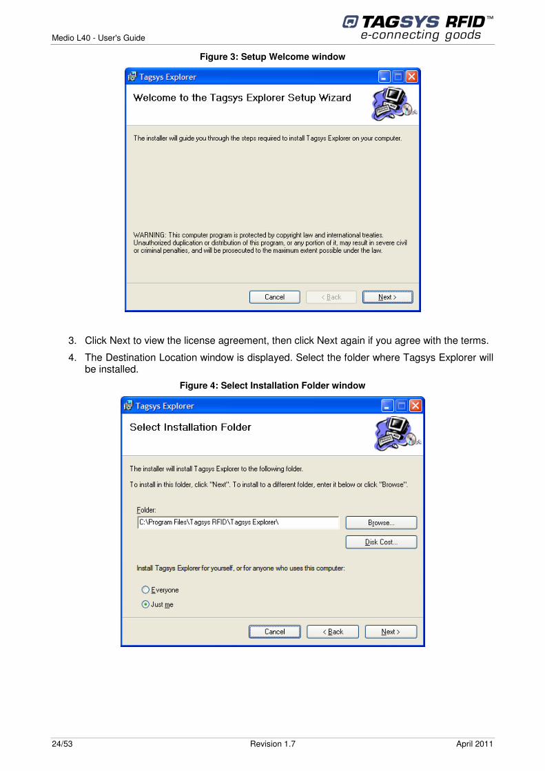
Figure 3: Setup Welcome window
3. Click Next to view the license agreement, then click Next again if you agree with the terms.
4. The Destination Location window is displayed. Select the folder where Tagsys Explorer will be installed.
Figure 4: Select Installation Folder window
Medio L40 - User's Guide
April 2011 Revision 1.7 25/53
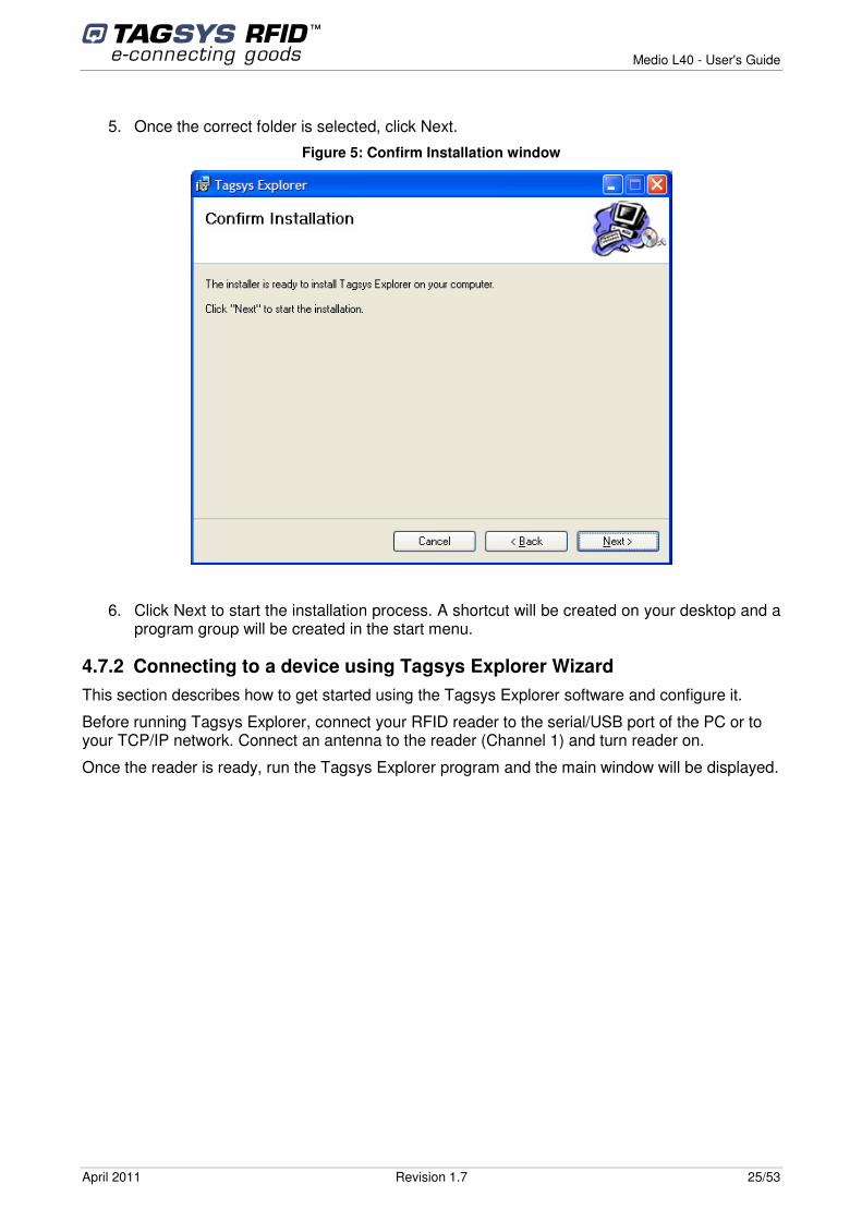
5. Once the correct folder is selected, click Next.
Figure 5: Confirm Installation window
6. Click Next to start the installation process. A shortcut will be created on your desktop and a program group will be created in the start menu.
4.7.2 Connecting to a device using Tagsys Explorer Wizard This section describes how to get started using the Tagsys Explorer software and configure it.
Before running Tagsys Explorer, connect your RFID reader to the serial/USB port of the PC or to your TCP/IP network. Connect an antenna to the reader (Channel 1) and turn reader on.
Once the reader is ready, run the Tagsys Explorer program and the main window will be displayed.
Medio L40 - User's Guide
26/53 Revision 1.7 April 2011
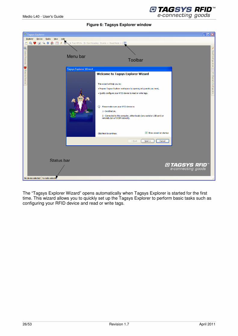
Figure 6: Tagsys Explorer window
The “Tagsys Explorer Wizard” opens automatically when Tagsys Explorer is started for the first time. This wizard allows you to quickly set up the Tagsys Explorer to perform basic tasks such as configuring your RFID device and read or write tags.
Toolbar
Menu bar
Status bar
Medio L40 - User's Guide
April 2011 Revision 1.7 27/53
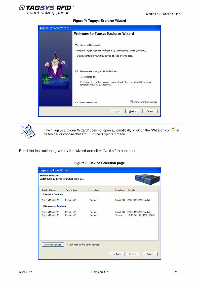
Figure 7: Tagsys Explorer Wizard
If the “Tagsys Explorer Wizard” does not open automatically, click on the “Wizard” icon in the toolbar or choose “Wizard…” in the “Explorer” menu.
Read the instructions given by the wizard and click “Next >” to continue.
Figure 8: Device Selection page
Medio L40 - User's Guide
28/53 Revision 1.7 April 2011
The Tagsys Explorer Wizard can automatically discover and display RFID devices plugged into your computer’s serial or USB ports or connected on a TCP/IP network.
Discovered devices are displayed under the “Discovered Devices” group. The same device can be displayed one or more times depending on the number of communication interfaces (Serial/USB, Ethernet) this device is connected to. The preferred connection is the “Ethernet” interface when available as it is the fastest communication interface.
You can restart a discovery at any time by clicking “Discover Devices”.
Devices that have been previously registered in Tagsys Explorer will appear under the “Favorite Devices” group. Favorite Devices are shortcuts to devices you are working with often and can be managed using the “Favorite Devices” panel. See Tagsys Explorer User’s Guide for more information.
To continue, choose the device you would like to use and click “Next >”. If necessary, this device will be automatically added to your “Favorite Devices”.
If a device with the same interface details appears both in “Favorite Devices” and in “Discovered Devices” groups, it does not matter in which group you select this device.
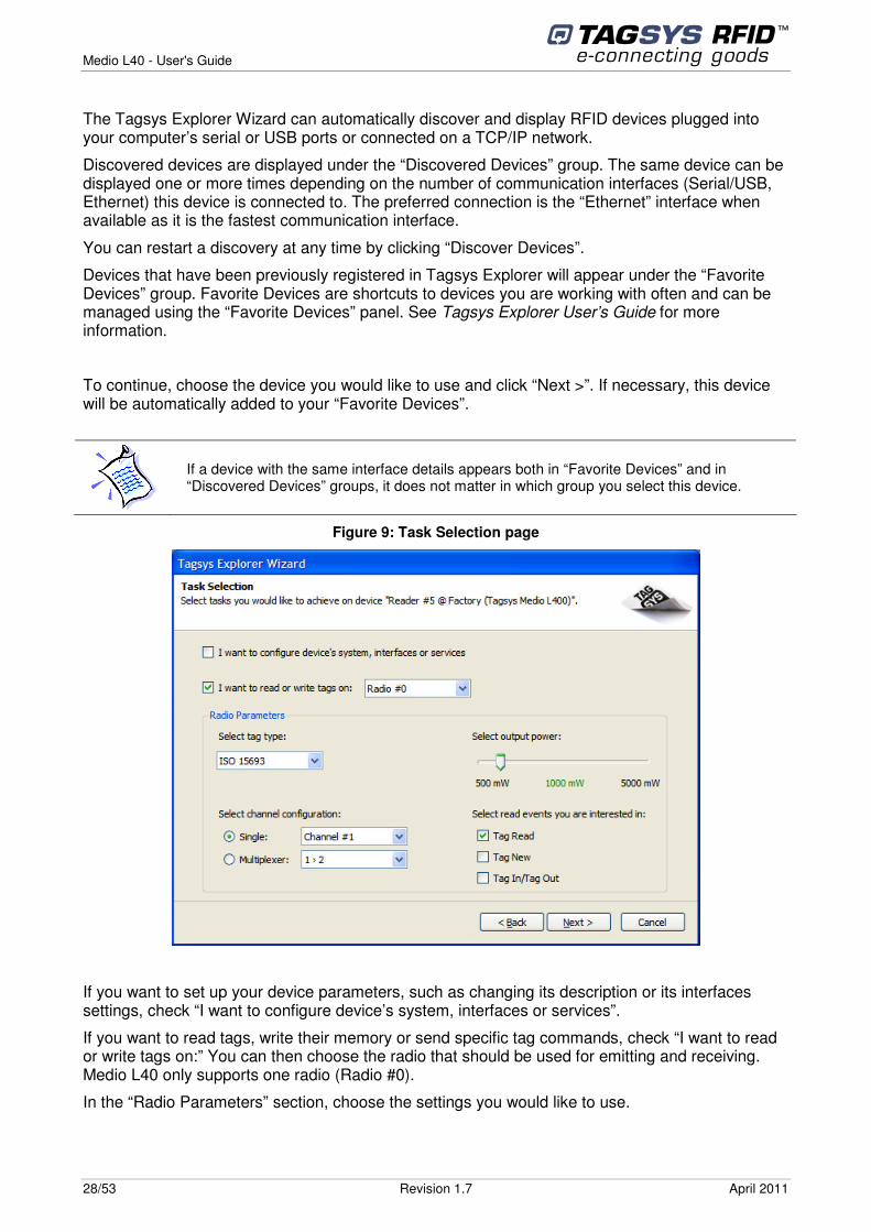
Figure 9: Task Selection page
If you want to set up your device parameters, such as changing its description or its interfaces settings, check “I want to configure device’s system, interfaces or services”.
If you want to read tags, write their memory or send specific tag commands, check “I want to read or write tags on:” You can then choose the radio that should be used for emitting and receiving. Medio L40 only supports one radio (Radio #0).
In the “Radio Parameters” section, choose the settings you would like to use.
Medio L40 - User's Guide
April 2011 Revision 1.7 29/53
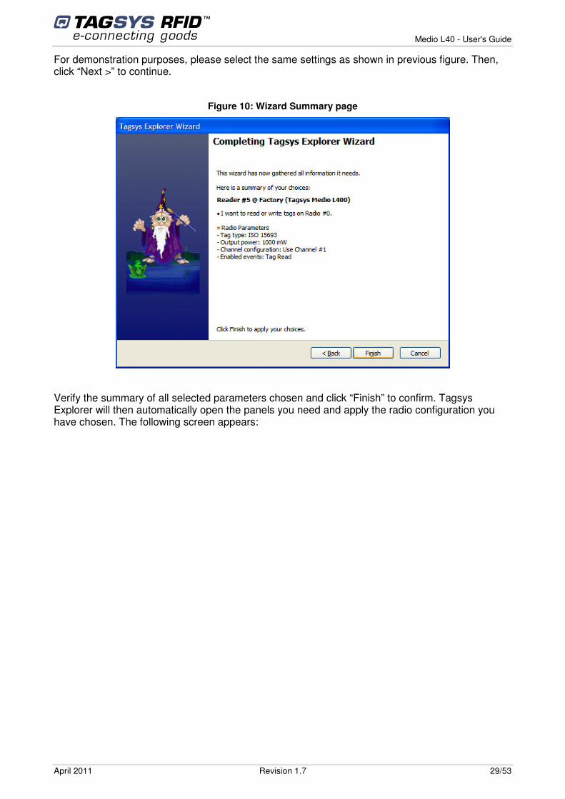
For demonstration purposes, please select the same settings as shown in previous figure. Then, click “Next >” to continue.
Figure 10: Wizard Summary page
Verify the summary of all selected parameters chosen and click “Finish” to confirm. Tagsys Explorer will then automatically open the panels you need and apply the radio configuration you have chosen. The following screen appears:
Medio L40 - User's Guide
30/53 Revision 1.7 April 2011
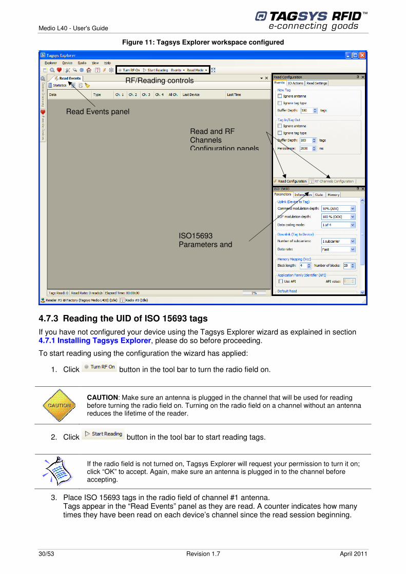
Figure 11: Tagsys Explorer workspace configured
4.7.3 Reading the UID of ISO 15693 tags If you have not configured your device using the Tagsys Explorer wizard as explained in section 4.7.1 Installing Tagsys Explorer, please do so before proceeding.
To start reading using the configuration the wizard has applied:
1. Click button in the tool bar to turn the radio field on.
CAUTION: Make sure an antenna is plugged in the channel that will be used for reading before turning the radio field on. Turning on the radio field on a channel without an antenna reduces the lifetime of the reader.
2. Click button in the tool bar to start reading tags.
If the radio field is not turned on, Tagsys Explorer will request your permission to turn it on; click “OK” to accept. Again, make sure an antenna is plugged in to the channel before accepting.
3. Place ISO 15693 tags in the radio field of channel #1 antenna. Tags appear in the “Read Events” panel as they are read. A counter indicates how many times they have been read on each device’s channel since the read session beginning.
RF/Reading controls
Read Events panel
Read and RF Channels Configuration panels
ISO15693
Parameters and Commands panel
Medio L40 - User's Guide
April 2011 Revision 1.7 31/53
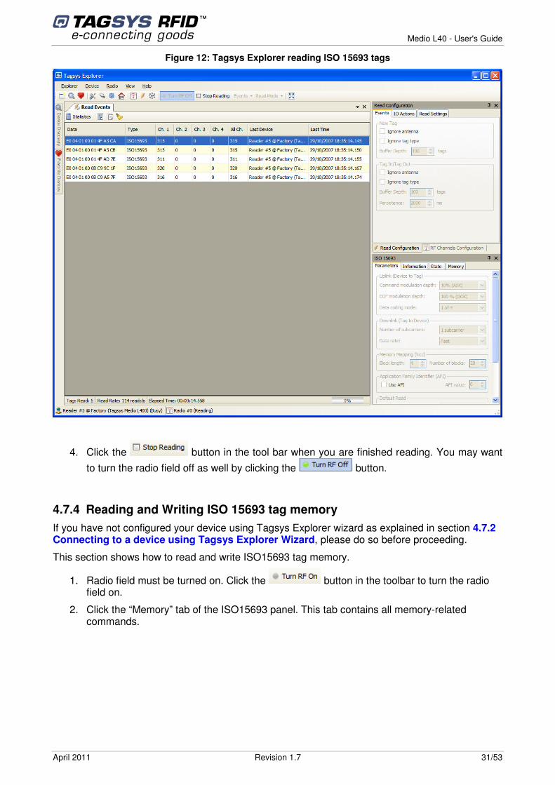
Figure 12: Tagsys Explorer reading ISO 15693 tags
4. Click the button in the tool bar when you are finished reading. You may want to turn the radio field off as well by clicking the button.
4.7.4 Reading and Writing ISO 15693 tag memory If you have not configured your device using Tagsys Explorer wizard as explained in section 4.7.2 Connecting to a device using Tagsys Explorer Wizard, please do so before proceeding.
This section shows how to read and write ISO15693 tag memory.
1. Radio field must be turned on. Click the button in the toolbar to turn the radio field on.
2. Click the “Memory” tab of the ISO15693 panel. This tab contains all memory-related commands.
Medio L40 - User's Guide
32/53 Revision 1.7 April 2011
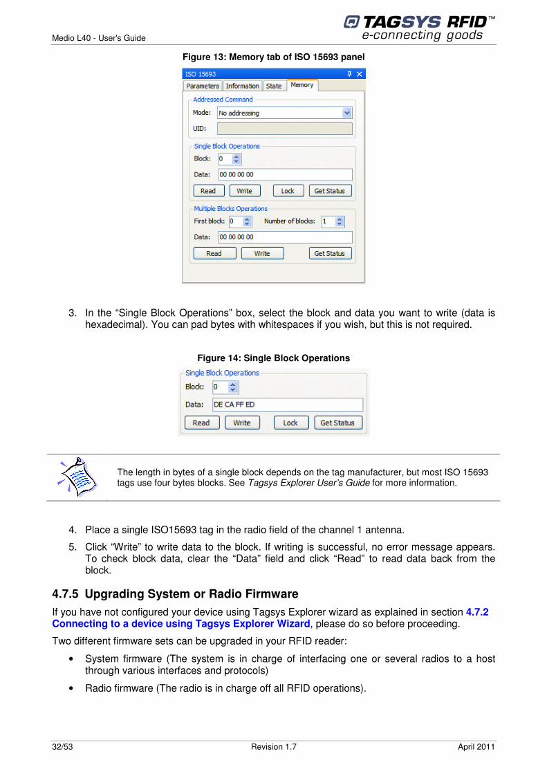
Figure 13: Memory tab of ISO 15693 panel
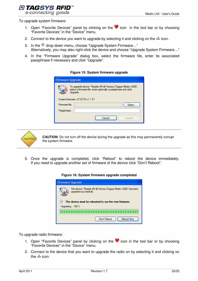
3. In the “Single Block Operations” box, select the block and data you want to write (data is hexadecimal). You can pad bytes with whitespaces if you wish, but this is not required.
Figure 14: Single Block Operations
The length in bytes of a single block depends on the tag manufacturer, but most ISO 15693 tags use four bytes blocks. See Tagsys Explorer User’s Guide for more information.
4. Place a single ISO15693 tag in the radio field of the channel 1 antenna.
5. Click “Write” to write data to the block. If writing is successful, no error message appears. To check block data, clear the “Data” field and click “Read” to read data back from the block.
4.7.5 Upgrading System or Radio Firmware If you have not configured your device using Tagsys Explorer wizard as explained in section 4.7.2 Connecting to a device using Tagsys Explorer Wizard, please do so before proceeding.
Two different firmware sets can be upgraded in your RFID reader:
• System firmware (The system is in charge of interfacing one or several radios to a host through various interfaces and protocols)
• Radio firmware (The radio is in charge off all RFID operations).
Medio L40 - User's Guide
April 2011 Revision 1.7 33/53
To upgrade system firmware:
1. Open “Favorite Devices” panel by clicking on the icon in the tool bar or by choosing “Favorite Devices” in the “Device” menu.
2. Connect to the device you want to upgrade by selecting it and clicking on the icon.
3. In the drop down menu, choose “Upgrade System Firmware…” Alternatively, you may also right-click the device and choose “Upgrade System Firmware…”
4. In the “Firmware Upgrade” dialog box, select the firmware file, enter its associated passphrase if necessary and click “Upgrade”.
Figure 15: System firmware upgrade
CAUTION: Do not turn off the device during the upgrade as this may permanently corrupt the system firmware.
5. Once the upgrade is completed, click “Reboot” to reboot the device immediately. If you need to upgrade another set of firmware of the device click “Don’t Reboot”.
Figure 16: System firmware upgrade completed
To upgrade radio firmware:
1. Open “Favorite Devices” panel by clicking on the icon in the tool bar or by choosing “Favorite Devices” in the “Device” menu.
2. Connect to the device that you want to upgrade the radio on by selecting it and clicking on the icon.
Medio L40 - User's Guide
34/53 Revision 1.7 April 2011
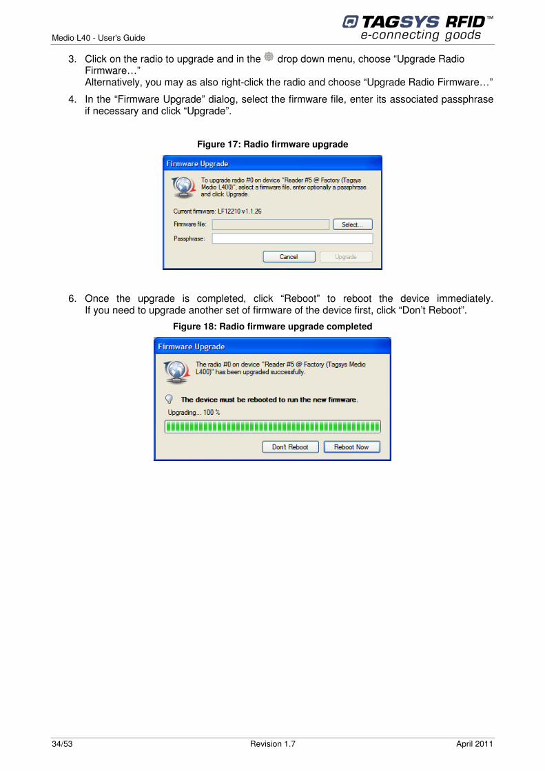
3. Click on the radio to upgrade and in the drop down menu, choose “Upgrade Radio Firmware…” Alternatively, you may as also right-click the radio and choose “Upgrade Radio Firmware…”
4. In the “Firmware Upgrade” dialog, select the firmware file, enter its associated passphrase if necessary and click “Upgrade”.
Figure 17: Radio firmware upgrade
6. Once the upgrade is completed, click “Reboot” to reboot the device immediately. If you need to upgrade another set of firmware of the device first, click “Don’t Reboot”.
Figure 18: Radio firmware upgrade completed
Medio L40 - User's Guide
April 2011 Revision 1.7 35/53
5 Advanced Notions 5.1 Reader Architecture
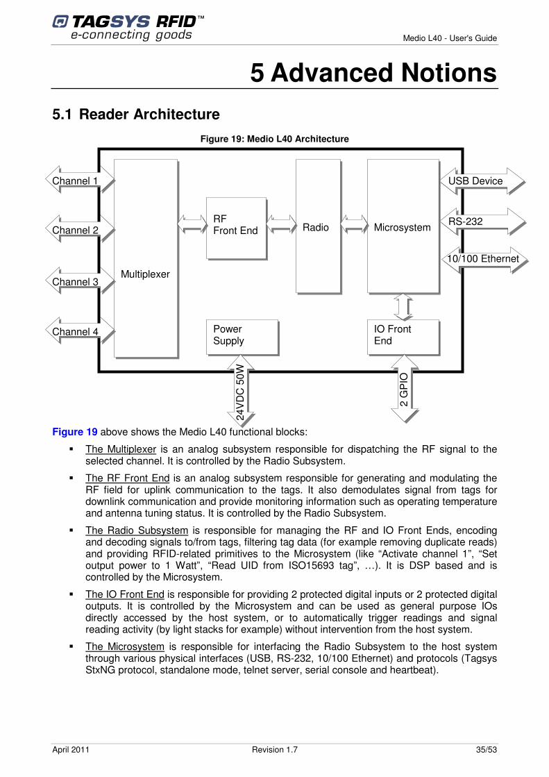
Figure 19: Medio L40 Architecture
Figure 19 above shows the Medio L40 functional blocks:
� The Multiplexer is an analog subsystem responsible for dispatching the RF signal to the selected channel. It is controlled by the Radio Subsystem.
� The RF Front End is an analog subsystem responsible for generating and modulating the RF field for uplink communication to the tags. It also demodulates signal from tags for downlink communication and provide monitoring information such as operating temperature and antenna tuning status. It is controlled by the Radio Subsystem.
� The Radio Subsystem is responsible for managing the RF and IO Front Ends, encoding and decoding signals to/from tags, filtering tag data (for example removing duplicate reads) and providing RFID-related primitives to the Microsystem (like “Activate channel 1”, “Set output power to 1 Watt”, “Read UID from ISO15693 tag”, …). It is DSP based and is controlled by the Microsystem.
� The IO Front End is responsible for providing 2 protected digital inputs or 2 protected digital outputs. It is controlled by the Microsystem and can be used as general purpose IOs directly accessed by the host system, or to automatically trigger readings and signal reading activity (by light stacks for example) without intervention from the host system.
� The Microsystem is responsible for interfacing the Radio Subsystem to the host system through various physical interfaces (USB, RS-232, 10/100 Ethernet) and protocols (Tagsys StxNG protocol, standalone mode, telnet server, serial console and heartbeat).
Radio
Microsystem
Multiplexer
RF Front End
Channel 1
Channel 2
Channel 3
Channel 4
USB Device
RS-232
10/100 Ethernet
Power Supply
24V
DC
50W
IO Front End
2 G
PIO
Medio L40 - User's Guide
36/53 Revision 1.7 April 2011
5.2 Reader to Host Protocols
5.2.1 TAGSYS StxNG TAGSYS StxNG is the protocol used by the Medio L40 reader to communicate with the host system. Upon start up, the Medio L40 reader starts listening for incoming frames over all of its interfaces:
� USB (seen as a virtual COM port from the host side)
� RS-232
� Primary and Secondary TCP ports (default ports are ports 4000 and 4001. Only one connection per port is accepted).
After a valid frame is received from one of the interfaces, the corresponding command is executed and a reply is sent back to the host.
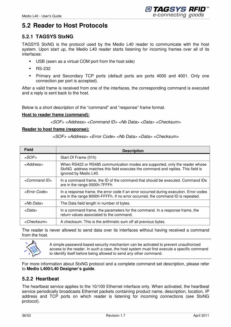
Below is a short description of the “command” and “response” frame format.
Host to reader frame (command):
<SOF> <Address> <Command ID> <Nb Data> <Data> <Checksum>
Reader to host frame (response):
<SOF> <Address> <Error Code> <Nb Data> <Data> <Checksum>
Field Description
<SOF> Start Of Frame (01h)
<Address> When RS422 or RS485 communication modes are supported, only the reader whose StxNG address matches this field executes the command and replies. This field is ignored by Medio L40.
<Command ID> In a command frame, the ID of the command that should be executed. Command IDs are in the range 0000h-7FFFh
<Error Code> In a response frame, the error code if an error occurred during execution. Error codes are in the range 8000h-FFFFh. If no error occurred, the command ID is repeated.
<Nb Data> The Data field length in number of bytes.
<Data> In a command frame, the parameters for the command. In a response frame, the return values associated to the command.
<Checksum> A checksum. This is the arithmetic sum off all previous bytes.
The reader is never allowed to send data over its interfaces without having received a command from the host.
For more information about StxNG protocol and a complete command set description, please refer to Medio L400/L40 Designer’s guide.
5.2.2 Heartbeat The heartbeat service applies to the 10/100 Ethernet interface only. When activated, the heartbeat service periodically broadcasts Ethernet packets containing product name, description, location, IP address and TCP ports on which reader is listening for incoming connections (see StxNG protocol).
A simple password-based security mechanism can be activated to prevent unauthorized access to the reader. In such a case, the host system must first execute a specific command to identify itself before being allowed to send any other command.
Medio L40 - User's Guide
April 2011 Revision 1.7 37/53
This heartbeat is useful to:
• Show Medio L40 readers connected to the same physical network as the host.
• Check that a Medio L40 reader is operating properly (in this case, the heartbeat acts as a watchdog).
For more information about heartbeat please refer to Medio L400/L40 Designer’s guide.
5.2.3 Telnet The telnet server applies to 10/100 Ethernet interface only. A host can connect to the reader using any standard telnet client. The Telnet server makes it possible to configure the microsystem only (serial port configuration, TCP/IP stack configuration, date/time configuration, version query…).
For more information about telnet server please refer to Medio L400/L40 Designer’s guide.
5.2.4 Serial console The serial console applies to RS-232 and USB interfaces only. A host can connect to the reader using any standard terminal application. The serial console makes it possible to configure the microsystem only (serial port configuration, TCP/IP stack configuration, date/time configuration, version query…).
The reader automatically detects if current data exchanges over its serial and USB ports are StxNG protocol frames or console frames and reacts accordingly. Consequently, there’s no need to configure those interfaces for console or StxNG protocol operation: both are simultaneously available.
For more information about serial console please refer to Medio L400/L40 Designer’s guide.
5.2.5 Standalone mode Standalone mode makes it possible to use the reader without the need for a host to control it. In this case, only the tag reading operation is available.
When standalone mode is activated, the reader automatically loads its last saved configuration upon start-up and initiates a read session. Each time a read event occurs, the reader sends a
RFID configuration and control (for example activating a channel and reading a tag) is not allowed with telnet server.
A simple password-based security mechanism can be activated to prevent unauthorized access to the reader.
RFID configuration and control (for example activating a channel and reading a tag) is not allowed with serial console.
A simple password-based security mechanism can be activated to prevent unauthorized access to the reader.
Medio L40 - User's Guide
38/53 Revision 1.7 April 2011
frame over its serial port. Frame format is as the following (all fields are ASCII, optional and customizable):
<Header><Timestamp><Radio ID><Event Type><Channel><Tag Type><Tag Data><Footer>
A watchdog can also be activated. In this case, a customizable frame is sent periodically over the serial port to indicate the reader is operating properly.
For more information about standalone mode operation and configuration, please refer to Medio L400/L40 Designer’s guide.
5.3 Reader operation principles
Most of the reader commands are executed in a synchronous manner. This means that the reader waits for an incoming request from the host, executes the associated operation then sends a reply containing operation execution status back to the host. Between the reception of two consecutive commands, the reader does nothing but wait for the next command.
The following commands are examples of commands executed in a synchronous manner:
• Configuration commands (configuring the TCP/IP stack, for example).
• Tag writing commands (writing an ISO15693 tag memory block, for example).
• Most tag reading commands (reading the locking status of an ISO15693 tag memory block, for example).
Synchronous commands that actually perform an operation on tags in the RF field (such as a writing operation, opposed to a configuration command) can only use a single channel (multiplexer can not be used). The channel and RF power that should be used for any subsequent synchronous tag operation is called the default RF configuration (specific commands exist to get/set this configuration).
An exception to the mechanism described above exists: the asynchronous read (or default read). Asynchronous read (or default read) can be activated or deactivated using the appropriate commands in the command set. During asynchronous read, the reader continuously tries to read all tags in the field. When a tag is detected, one or several read events are asynchronously pushed into an internal buffer (the event buffer). The host system then needs to poll the event buffer periodically to retrieve the latest events.
One can specify the kind of read events that should be reported during asynchronous read, as well as several options (called read modes) that should be applied during asynchronous read. The following sections provide more details about the different read events, as well as the different read modes.
5.3.1 Notion of read modes During asynchronous read (or default read), the reader continuously tries to read all tags in the RF field. Several options can be applied that modify the reader’s behavior during asynchronous read:
• “Multiplexer”: If this mode is active, the reader uses the multiplexer instead of the default RF configuration for reading. The multiplexer makes it possible to define a sequence of antennas, tag types and RF output powers that will be automatically used during the reading process. For example, a user can configure the multiplexer so that reader tries to read ISO15693 tags for 100ms on channel 1 at 1Watt, then ICode UID tags for 50ms on channel 1 at 2Watts, then ISO15693 tags for 100ms on channel 2 at 1Watt, then ICode UID tags for 50ms on channel 2 at 2Watts.
• “Input triggered”: If this mode is active, the reader waits for GPIO Input #1 to become active in order to activate the RF field and start reading. When GPIO Input #1 gets back to
Medio L40 - User's Guide
April 2011 Revision 1.7 39/53
inactive state, RF field is turned off and the reader stops reading until input is active again. Active input level (low or high) is software configurable.
• “Output feedback”: If this mode is active, the reader uses GPIO Outputs #2 to signal reading activity. GPIO Output #2 is activated when the reader “sees” tags in the RF field. The time an output remains active after the corresponding event has occurred is software configurable.
A user can activate one or several read modes at once, depending on the application requirements.
5.3.2 Notion of events During asynchronous read (or default read), the reader continuously tries to read all tags in the RF field. When a tag is detected, one or several events are pushed into an internal event buffer. Those events contain information such as the kind of event (see below), a timestamp, the channel on which the event occurred, the tag type and the associated tag data (UID, memory…). The following events are supported:
• “Tag Read”: This event is pushed each time a valid tag frame is decoded, without further processing. When activated, this event may be triggered several hundreds of times per second and is consequently bandwidth consuming. It is often used for testing purpose only.
• “Tag New”: This event is pushed each time a new tag is detected. If the same tag is detected several times, it will be reported only once.
• “Tag In”: This event is pushed each time a tag enters the RF field.
• “Tag Out”: This event is pushed each time a tag leaves the RF field.
• “Tag No Read”: When Input triggered read mode is active, this event is pushed when the trigger condition ends and no tag was detected in the RF field. When Input triggered read mode is inactive, this event is never pushed.
A user can register for one or several events at once, depending on the application requirements.
For example, if a user registers for all events and a tag enters the RF field, stays in the field for some time, and then leaves the field, the sequence of events pushed into the event buffer will be:
• “Tag Read”
• “Tag New”
• “Tag In”
• “Tag Read” (repeated as long as the tag remains in the field)
• “Tag Out”
If the same tag re-enters the RF field at a later time, stays in the field for a period of time, then leaves the field, the sequence of events pushed into the event buffer will be:
• “Tag Read”
• “Tag In”
• “Tag Read” (repeated as long as the tag remains in the field)
• “Tag Out”
Medio L40 - User's Guide
40/53 Revision 1.7 April 2011
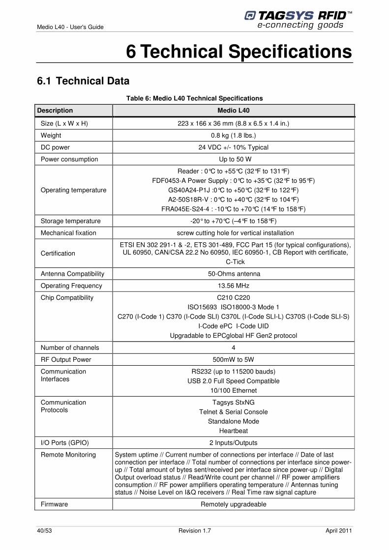
6 Technical Specifications 6.1 Technical Data
Table 6: Medio L40 Technical Specifications
Description Medio L40
Size (L x W x H) 223 x 166 x 36 mm (8.8 x 6.5 x 1.4 in.)
Weight 0.8 kg (1.8 lbs.)
DC power 24 VDC +/- 10% Typical
Power consumption Up to 50 W
Operating temperature
Reader : 0°C to +55°C (32°F to 131°F) FDF0453-A Power Supply : 0°C to +35°C (32°F to 95°F)
GS40A24-P1J :0°C to +50°C (32°F to 122°F) A2-50S18R-V : 0°C to +40°C (32°F to 104°F)
FRA045E-S24-4 : -10°C to +70°C (14°F to 158°F)
Storage temperature -20° to +70°C (–4°F to 158°F)
Mechanical fixation screw cutting hole for vertical installation
Certification ETSI EN 302 291-1 & -2, ETS 301-489, FCC Part 15 (for typical configurations), UL 60950, CAN/CSA 22.2 No 60950, IEC 60950-1, CB Report with certificate,
C-Tick
Antenna Compatibility 50-Ohms antenna
Operating Frequency 13.56 MHz
Chip Compatibility C210 C220 ISO15693 ISO18000-3 Mode 1
C270 (I-Code 1) C370 (I-Code SLI) C370L (I-Code SLI-L) C370S (I-Code SLI-S) I-Code ePC I-Code UID
Upgradable to EPCglobal HF Gen2 protocol
Number of channels 4
RF Output Power 500mW to 5W
Communication Interfaces
RS232 (up to 115200 bauds) USB 2.0 Full Speed Compatible
10/100 Ethernet
Communication Protocols
Tagsys StxNG Telnet & Serial Console
Standalone Mode Heartbeat
I/O Ports (GPIO) 2 Inputs/Outputs
Remote Monitoring System uptime // Current number of connections per interface // Date of last connection per interface // Total number of connections per interface since power-up // Total amount of bytes sent/received per interface since power-up // Digital Output overload status // Read/Write count per channel // RF power amplifiers consumption // RF power amplifiers operating temperature // Antennas tuning status // Noise Level on I&Q receivers // Real Time raw signal capture
Firmware Remotely upgradeable
Medio L40 - User's Guide
April 2011 Revision 1.7 41/53
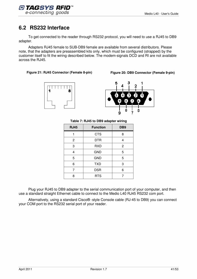
6.2 RS232 Interface
To get connected to the reader through RS232 protocol, you will need to use a RJ45 to DB9 adapter.
Adapters RJ45 female to SUB-DB9 female are available from several distributors. Please note, that the adapters are preassembled kits only, which must be configured (strapped) by the customer itself to fit the wiring described below. The modem-signals DCD and RI are not available across the RJ45.
Table 7: RJ45 to DB9 adapter wiring
RJ45 Function DB9
1 CTS 8
2 DTR 4
3 RXD 2
4 GND 5
5 GND 5
6 TXD 3
7 DSR 6
8 RTS 7
Plug your RJ45 to DB9 adapter to the serial communication port of your computer, and then use a standard straight Ethernet cable to connect to the Medio L40 RJ45 RS232 com port.
Alternatively, using a standard Cisco® -style Console cable (RJ-45 to DB9) you can connect your COM port to the RS232 serial port of your reader.
Figure 21: RJ45 Connector (Female 8-pin)
Figure 20: DB9 Connector (Female 9-pin)
Medio L40 - User's Guide
42/53 Revision 1.7 April 2011
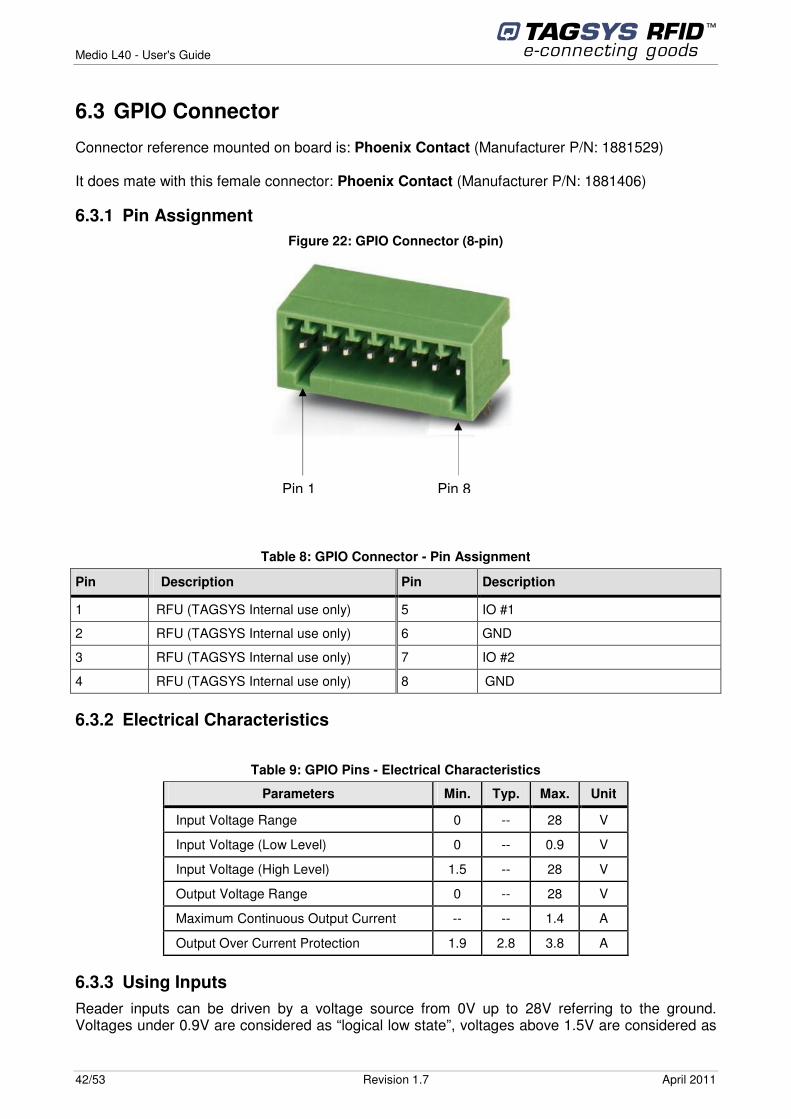
6.3 GPIO Connector
Connector reference mounted on board is: Phoenix Contact (Manufacturer P/N: 1881529) It does mate with this female connector: Phoenix Contact (Manufacturer P/N: 1881406)
6.3.1 Pin Assignment Figure 22: GPIO Connector (8-pin)
Table 8: GPIO Connector - Pin Assignment
Pin Description Pin Description
1 RFU (TAGSYS Internal use only) 5 IO #1
2 RFU (TAGSYS Internal use only) 6 GND
3 RFU (TAGSYS Internal use only) 7 IO #2
4 RFU (TAGSYS Internal use only) 8 GND
6.3.2 Electrical Characteristics
Table 9: GPIO Pins - Electrical Characteristics
Parameters Min. Typ. Max. Unit
Input Voltage Range 0 -- 28 V
Input Voltage (Low Level) 0 -- 0.9 V
Input Voltage (High Level) 1.5 -- 28 V
Output Voltage Range 0 -- 28 V
Maximum Continuous Output Current -- -- 1.4 A
Output Over Current Protection 1.9 2.8 3.8 A
6.3.3 Using Inputs Reader inputs can be driven by a voltage source from 0V up to 28V referring to the ground. Voltages under 0.9V are considered as “logical low state”, voltages above 1.5V are considered as
Pin 1 Pin 8
Medio L40 - User's Guide
April 2011 Revision 1.7 43/53
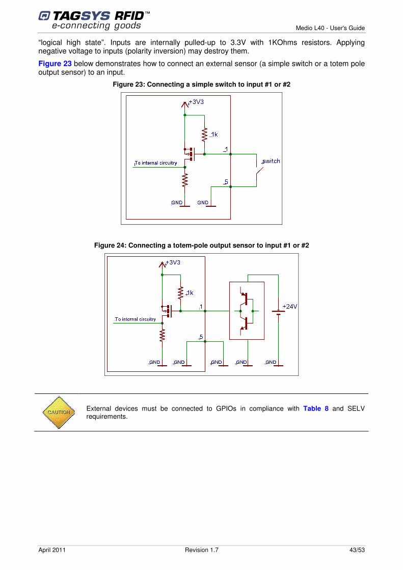
“logical high state”. Inputs are internally pulled-up to 3.3V with 1KOhms resistors. Applying negative voltage to inputs (polarity inversion) may destroy them.
Figure 23 below demonstrates how to connect an external sensor (a simple switch or a totem pole output sensor) to an input.
Figure 23: Connecting a simple switch to input #1 or #2
Figure 24: Connecting a totem-pole output sensor to input #1 or #2
External devices must be connected to GPIOs in compliance with Table 8 and SELV requirements.
Medio L40 - User's Guide
44/53 Revision 1.7 April 2011
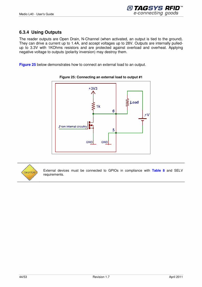
6.3.4 Using Outputs The reader outputs are Open Drain, N-Channel (when activated, an output is tied to the ground). They can drive a current up to 1.4A, and accept voltages up to 28V. Outputs are internally pulled-up to 3.3V with 1KOhms resistors and are protected against overload and overheat. Applying negative voltage to outputs (polarity inversion) may destroy them.
Figure 25 below demonstrates how to connect an external load to an output.
Figure 25: Connecting an external load to output #1
External devices must be connected to GPIOs in compliance with Table 8 and SELV requirements.
Medio L40 - User's Guide
April 2011 Revision 1.7 45/53
7 Electrical Characteristics This chapter provides information about AC and DC and characteristics for all connectors. It
also gives timing characteristics for the different interfaces.
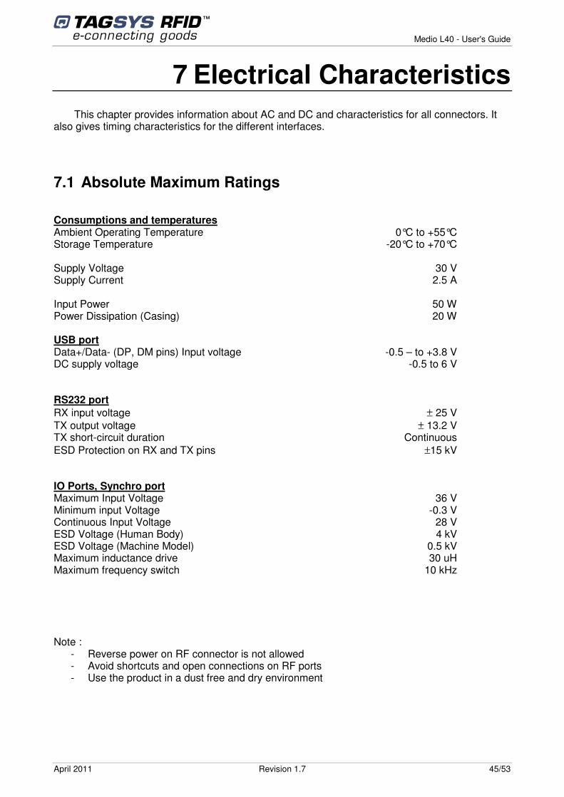
7.1 Absolute Maximum Ratings
Consumptions and temperatures Ambient Operating Temperature 0°C to +55°C Storage Temperature -20°C to +70°C Supply Voltage 30 V Supply Current 2.5 A Input Power 50 W Power Dissipation (Casing) 20 W USB port Data+/Data- (DP, DM pins) Input voltage -0.5 – to +3.8 V DC supply voltage -0.5 to 6 V RS232 port RX input voltage ± 25 V TX output voltage ± 13.2 V TX short-circuit duration Continuous ESD Protection on RX and TX pins ±15 kV IO Ports, Synchro port Maximum Input Voltage 36 V Minimum input Voltage -0.3 V Continuous Input Voltage 28 V ESD Voltage (Human Body) 4 kV ESD Voltage (Machine Model) 0.5 kV Maximum inductance drive 30 uH Maximum frequency switch 10 kHz Note :
- Reverse power on RF connector is not allowed - Avoid shortcuts and open connections on RF ports - Use the product in a dust free and dry environment
Medio L40 - User's Guide
46/53 Revision 1.7 April 2011
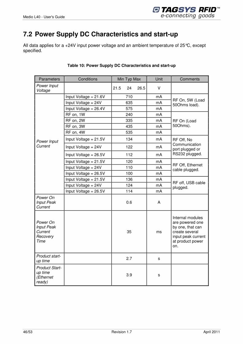
7.2 Power Supply DC Characteristics and start-up
All data applies for a +24V input power voltage and an ambient temperature of 25°C, except specified.
Table 10: Power Supply DC Characteristics and start-up
Parameters Conditions Min Typ Max Unit Comments
Power Input Voltage 21.5 24 26.5 V
Input Voltage = 21.6V 710 mA Input Voltage = 24V 635 mA Input Voltage = 26.4V 575 mA
RF On, 5W (Load 50Ohms load).
RF on, 1W 240 mA RF on, 2W 335 mA RF on, 3W 435 mA RF on, 4W 535 mA
RF On (Load 50Ohms).
Input Voltage = 21.5V 134 mA
Input Voltage = 24V 122 mA
Input Voltage = 26.5V 112 mA
RF Off, No Communication port plugged or RS232 plugged.
Input Voltage = 21.5V 120 mA Input Voltage = 24V 110 mA Input Voltage = 26.5V 100 mA
RF Off, Ethernet cable plugged.
Input Voltage = 21.5V 136 mA Input Voltage = 24V 124 mA
Power Input Current
Input Voltage = 26.5V 114 mA
RF off, USB cable plugged.
Power On Input Peak Current
0.6 A
Power On Input Peak Current Recovery Time
35 ms
Internal modules are powered one by one, that can create several input peak current at product power on.
Product start-up time 2.7 s
Product Start-up time (Ethernet ready)
3.9 s
Medio L40 - User's Guide
April 2011 Revision 1.7 47/53
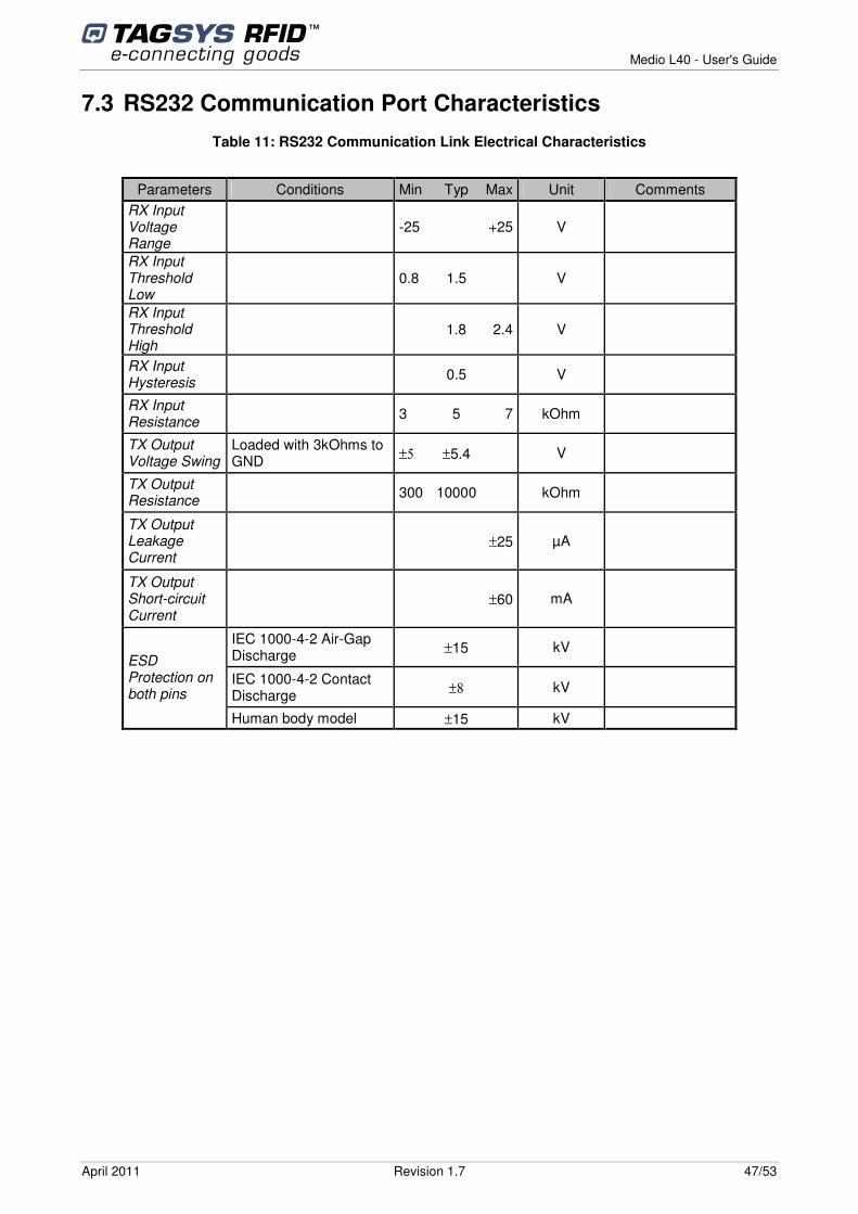
7.3 RS232 Communication Port Characteristics Table 11: RS232 Communication Link Electrical Characteristics
Parameters Conditions Min Typ Max Unit Comments
RX Input Voltage Range
-25 +25 V
RX Input Threshold Low
0.8 1.5 V
RX Input Threshold High
1.8 2.4 V
RX Input Hysteresis 0.5 V
RX Input Resistance 3 5 7 kOhm
TX Output Voltage Swing
Loaded with 3kOhms to GND ±5 ±5.4 V
TX Output Resistance 300 10000 kOhm
TX Output Leakage Current
±25 µA
TX Output Short-circuit Current
±60 mA
IEC 1000-4-2 Air-Gap Discharge ±15 kV
IEC 1000-4-2 Contact Discharge ±8 kV
ESD Protection on both pins
Human body model ±15 kV
Medio L40 - User's Guide
48/53 Revision 1.7 April 2011
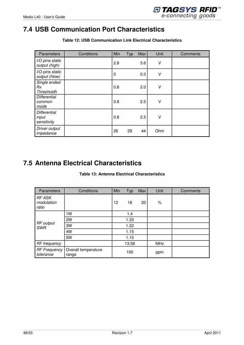
7.4 USB Communication Port Characteristics Table 12: USB Communication Link Electrical Characteristics
Parameters Conditions Min Typ Max Unit Comments
I/O pins static output (high) 2.8 3.6 V
I/O pins static output (hlow) 0 0.3 V
Single ended Rx Thresholdh
0.8 2.0 V
Differential common mode
0.8 2.5 V
Differential input sensitivity
0.8 2.5 V
Driver output impedance 26 29 44 Ohm
7.5 Antenna Electrical Characteristics Table 13: Antenna Electrical Characteristics
Parameters Conditions Min Typ Max Unit Comments
RF ASK modulation ratio
12 16 20 %
1W 1.4 2W 1.33 3W 1.22 4W 1.15
RF output SWR
5W 1.15 RF frequency 13.56 MHz RF Frequency tolerance
Overall temperature range 100 ppm
Medio L40 - User's Guide
April 2011 Revision 1.7 49/53
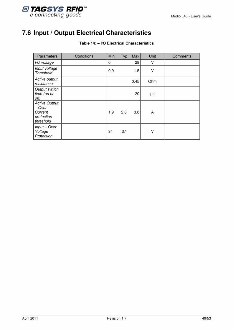
7.6 Input / Output Electrical Characteristics Table 14: – I/O Electrical Characteristics
Parameters Conditions Min Typ Max Unit Comments
I/O voltage 0 28 V Input voltage Threshold 0.9 1.5 V
Active output resistance 0.45 Ohm
Output switch time (on or off)
20 µs
Active Output – Over Current protection threshold
1.9 2.8 3.8 A
Input – Over Voltage Protection
34 37 V
Medio L40 - User's Guide
50/53 Revision 1.7 April 2011
8 Mechanical Characteristics
8.1 Dimensions and General Mechanical Information
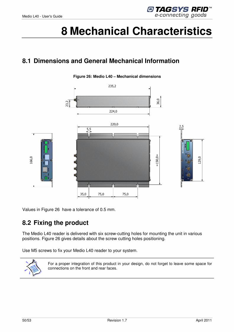
Figure 26: Medio L40 – Mechanical dimensions
Values in Figure 26 have a tolerance of 0.5 mm.
8.2 Fixing the product
The Medio L40 reader is delivered with six screw-cutting holes for mounting the unit in various positions. Figure 26 gives details about the screw cutting holes positioning.
Use M5 screws to fix your Medio L40 reader to your system.
For a proper integration of this product in your design, do not forget to leave some space for connections on the front and rear faces.
April 2011 Revision 1.7 51/53
9 Warranty Conditions 9.1 Warranty
TAGSYS warrants that this Product shall comply with the functional specifications set forth herein for a period of one year from the date of delivery to the Buyer.
This warranty is valid for the original Buyer of the Product and is not assignable or transferable to any other party.
TAGSYS cannot be responsible in any way for, and disclaims any liability in connection with the operation or performance of:
� any product in which the Product is incorporated;
� any equipment not supplied by TAGSYS which is attached to or used in connection with the Product; or
� the Product with any equipment
This warranty does only cover the Product to the exclusion of any such other equipment.
Optimal operation and performance of the Product are obtained by using TAGSYS’ readers, by applying TAGSYS installation guidelines and by having your installation reviewed by a TAGSYS’ technical consultant.
TAGSYS warranty does not cover the installation, maintenance or service of the Product and is strictly limited to the replacement of Products considered as defective by TAGSYS and returned according to the return procedure defined below; in such case, TAGSYS will, at TAGSYS’ option, either replace every defective Product by one new Product or refund the purchase price paid by Buyer to TAGSYS for the defective Product.
9.2 Warranty Exclusions
� Defects or damages resulting from storage of the Product under conditions which do not comply with TAGSYS specifications or normal usage
� Defects or damages resulting from use of the Product in abnormal conditions (abnormal conditions being defined as any conditions exceeding the ones stated in the product specifications).
� Defects or damages from misuse, accident or neglect.
� Defects from improper testing, operation, maintenance or installation.
� Defects from alteration, modification except modifications or adjustments specifically described in this Product reference guide, adjustment or repair, or any attempt to do any of the foregoing, by anyone other than TAGSYS.
� Any action on Product that prevents TAGSYS from performing an inspection and test of the Product in case of a warranty claim.
� Tampering with or abuse of the Product.
� Any use or incorporation by the Buyer or a third party of TAGSYS' Product into life saving or life support devices or systems, or any related products; TAGSYS expressly excludes any liability for such use.
Medio L40 - User's Guide
52/53 Revision 1.7 April 2011
9.2.1 General Provisions This warranty sets forth the full extent of TAGSYS responsibility regarding the Product.
In any event, TAGSYS warranty is strictly limited to (at TAGSYS’ sole option) the replacement or refund of the Products purchase price to TAGSYS, of Products considered as defective by TAGSYS.
The remedy provided above is in lieu and to the exclusion of all other remedies, obligations or liabilities on the part of TAGSYS for damages, whether in contract, tort or otherwise, and including but not limited to, damages for any defects in the Products or for any injury, damage, or loss resulting from such defects or from any work done in connection therewith or for consequential loss, whether based upon lost goodwill, lost resale profits, impairment of other goods or arising from claims by third parties or otherwise.
TAGSYS disclaims any explicit warranty not provided herein and any implied warranty, guaranty or representation as to performance, quality and absence of hidden defects, and any remedy for breach of contract, which but for this provision, might arise by implication, operation of law, custom of trade or course of dealing, including implied warranties of merchantability and fitness for a particular purpose.
9.2.2 How to Return Defective Products The Buyer shall notify TAGSYS of the defects within 15 working days after the defects are discovered.
Defective Products must be returned to TAGSYS after assignment by a TAGSYS Quality Department representative of an RMA (Return Material Authorization) number. No Products shall be returned without their proof of purchase and without the acceptance number relating to the return procedure.
All Products shall be returned with a report from the Buyer stating the complete details of the alleged defect.
Call +33 (0) 4 42 18 89 36 for return authorization and shipping address.
If returned Products prove to be non-defective, a charge will be applied to cover TAGSYS’ analysis cost and shipping costs.
If the warranty does not apply for returned Products (due to age, or application of a warranty exclusion clause), a quote for replacement will be issued, and no replacement will be granted until a valid purchase order is received. If no purchase order is received within 30 days after the date of TAGSYS quote, TAGSYS will return the products and charge the analysis cost and shipping costs.
All replaced Products shall become the property of TAGSYS.
The Product Return Form is included on the following page. This form should accompany any product you need to return to TAGSYS for analysis in the event of a problem.

April 2011 Revision 1.7 53/53
Product Return Form Customer Profile: Company: ................................................................ Address: .................................................................................................................................................................................................................................... City & State:............................................................. Zip Code: ................................................................. Country: ...................................................................
Contact Name: ....................................................... Contact e-mail: ...................................................... Contact Phone: ...................................................... Contact Fax:...........................................................
Order identification: Product Name:......................................................... Order Number (OEF):..............................................
Invoice Number: ..................................................... Return Quantity: ....................................................
Reason for return: ......................................................................................................................................................................... ......................................................................................................................................................................... ......................................................................................................................................................................... ......................................................................................................................................................................... .........................................................................................................................................................................
To inform TAGSYS of this return, please email it to [email protected]
Address to ship the product with this document attached: TAGSYS
QUALITY DEPARTMENT TAGSYS – 785 Voie Antiope, Athélia III,
13600 La Ciotat, France
To inform TAGSYS of this return, please also fax it to your Customer Service Representative
+33 (0) 4 42 18 89 01
Return Procedure: The product returned will go through stringent quality controls. A final analysis report will be sent to you as soon as possible.
Please contact your Quality Service representative for further details. +33 (0) 4 42 18 89 36
This product bears the selective sorting symbol for waste electrical and electronic equipment (WEEE) This means that this product must be handled pursuant to European Directive 2002/96/EC in order to be recycled or dismantled to minimize its impact on the environment. For further information, please contact your local or regional authorities.


![conv60310acu17114anexo1 - Trivia [SP]data.triviasp.com.ar/files/parte3/conv60310acu17114anexo1.pdf · medio oficial medio oficial a dante medio oficial udante udante ante medio oficial](https://img.pdfslide.us/doc/110x75/5e3099bd91239e6f90165708/conv60310acu17114anexo1-trivia-spdata-medio-oficial-medio-oficial-a-dante-medio.jpg)