Embed Size (px)
Citation preview

8/2/2019 Medidor Electrico Analizador de Redes Pm800 Shneider
http://slidepdf.com/reader/full/medidor-electrico-analizador-de-redes-pm800-shneider 1/72
PowerLogic ® Series 800 Power MeterPM820, PM850, PM870
63230-500-224A1 6/2006
Retain for future use.
Installation manual

8/2/2019 Medidor Electrico Analizador de Redes Pm800 Shneider
http://slidepdf.com/reader/full/medidor-electrico-analizador-de-redes-pm800-shneider 2/72

8/2/2019 Medidor Electrico Analizador de Redes Pm800 Shneider
http://slidepdf.com/reader/full/medidor-electrico-analizador-de-redes-pm800-shneider 3/72
© 2006 Schneider Electric All Rights Reserved EN–i
E N G
L I S H
HAZARD CATEGORIES AND SPECIAL SYMBOLS
Read these instructions carefully and look at the equipment to
become familiar with the device before trying to install, operate,
service, or maintain it. The following special messages may appearthroughout this bulletin or on the equipment to warn of potential
hazards or to call attention to information that clarifies or simplifies a
procedure.
The addition of either symbol to a “Danger” or “Warning” safety label
indicates that an electrical hazard exists which will result in personal
injury if the instructions are not followed.
This is the safety alert symbol. It is used to alert you to potential
personal injury hazards. Obey all safety messages that follow thissymbol to avoid possible injury or death.
NOTE: Provides additional information to clarify or simplify a
procedure.
PLEASE NOTE
Electrical equipment should be installed, operated, serviced, and
maintained only by qualified personnel. No responsibility is assumed
by Schneider Electric for any consequences arising out of the use ofthis material.
DANGERDANGER indicates an imminently hazardous situation which, if not avoided,
will result in death or serious injury.
WARNING
WARNING indicates a potentially hazardous situation which, if not avoided,can result in death or serious injury.
CAUTION
CAUTION indicates a potentially hazardous situation which, if not avoided,
can result in minor or moderate injury.
CAUTION
CAUTION, used without the safety alert symbol, indicates a potentially
hazardous situation which, if not avoided, can result in property damage.

8/2/2019 Medidor Electrico Analizador de Redes Pm800 Shneider
http://slidepdf.com/reader/full/medidor-electrico-analizador-de-redes-pm800-shneider 4/72
© 2006 Schneider Electric All Rights ReservedEN–ii
E NG
L I S H
CLASS A FCC STATEMENT
This equipment has been tested and found to comply with the limits
for a Class A digital device, pursuant to part 15 of the FCC Rules.
These limits are designed to provide reasonable protection againstharmful interference when the equipment is operated in a commercial
environment. This equipment generates, uses, and can radiate radio
frequency energy and, if not installed and used in accordance with
the instruction manual, may cause harmful interference to radio
communications. Operation of this equipment in a residential area is
likely to cause harmful interference in which case the user will be
required to correct the interference at his own expense. This Class A
digital apparatus complies with Canadian ICES-003.
8/2/2019 Medidor Electrico Analizador de Redes Pm800 Shneider
http://slidepdf.com/reader/full/medidor-electrico-analizador-de-redes-pm800-shneider 5/72
© 2006 Schneider Electric All Rights Reserved
63230-500-224A1 PowerLogic ® Series 800 Power Meter6/2006 Table of Contents
EN–iii
E N
G L I S H
CHAPTER 1—TABLE OF CONTENTS
CHAPTER 1—INTRODUCTION . . . . . . . . . . . . . . . . . . . . . . . . . . . . . . . . . . . . . . . . . . . . . . . . . . 1
About This Manual . . . . . . . . . . . . . . . . . . . . . . . . . . . . . . . . . . . . . . . . . . . . . . . . . . . . . . . . . . 1
Topics Not Covered in This Manual . . . . . . . . . . . . . . . . . . . . . . . . . . . . . . . . . . . . . . . . . 2
Power Meter Hardware . . . . . . . . . . . . . . . . . . . . . . . . . . . . . . . . . . . . . . . . . . . . . . . . . . . . . . 3Power Meter Without Display . . . . . . . . . . . . . . . . . . . . . . . . . . . . . . . . . . . . . . . . . . . . . . 4
Power Meter With Remote Display . . . . . . . . . . . . . . . . . . . . . . . . . . . . . . . . . . . . . . . . . . 5
Power Meter Parts and Accessories . . . . . . . . . . . . . . . . . . . . . . . . . . . . . . . . . . . . . . . . . 6
Box Contents . . . . . . . . . . . . . . . . . . . . . . . . . . . . . . . . . . . . . . . . . . . . . . . . . . . . . . . . . . . . . . 7
Features . . . . . . . . . . . . . . . . . . . . . . . . . . . . . . . . . . . . . . . . . . . . . . . . . . . . . . . . . . . . . . . . . . 8
Firmware . . . . . . . . . . . . . . . . . . . . . . . . . . . . . . . . . . . . . . . . . . . . . . . . . . . . . . . . . . . . . . . . . 9
CHAPTER 2—SAFETY PRECAUTIONS . . . . . . . . . . . . . . . . . . . . . . . . . . . . . . . . . . . . . . . . . . 11
CHAPTER 3—INSTALLATION . . . . . . . . . . . . . . . . . . . . . . . . . . . . . . . . . . . . . . . . . . . . . . . . . . 13
Installation Considerations . . . . . . . . . . . . . . . . . . . . . . . . . . . . . . . . . . . . . . . . . . . . . . . . . . . 13
Power Meter With Integrated Display . . . . . . . . . . . . . . . . . . . . . . . . . . . . . . . . . . . . . . . . . . 15
Dimensions . . . . . . . . . . . . . . . . . . . . . . . . . . . . . . . . . . . . . . . . . . . . . . . . . . . . . . . . . . . 15
Mounting . . . . . . . . . . . . . . . . . . . . . . . . . . . . . . . . . . . . . . . . . . . . . . . . . . . . . . . . . . . . . 15
Mounting a Power Meter with an Integrated Display . . . . . . . . . . . . . . . . . . . . . . . . . 17
Replacing Analog Meters . . . . . . . . . . . . . . . . . . . . . . . . . . . . . . . . . . . . . . . . . . . . . 18
Power Meter Without Display . . . . . . . . . . . . . . . . . . . . . . . . . . . . . . . . . . . . . . . . . . . . . . . . . 20
DIN Rail Mounting . . . . . . . . . . . . . . . . . . . . . . . . . . . . . . . . . . . . . . . . . . . . . . . . . . . . . . 20
Power Meter With Remote Display . . . . . . . . . . . . . . . . . . . . . . . . . . . . . . . . . . . . . . . . . . . . 21
PM8RDA Dimensions . . . . . . . . . . . . . . . . . . . . . . . . . . . . . . . . . . . . . . . . . . . . . . . . . . . 21
PM8RDA Installation . . . . . . . . . . . . . . . . . . . . . . . . . . . . . . . . . . . . . . . . . . . . . . . . . . . . 22
PM8RD Dimensions and Mounting Options . . . . . . . . . . . . . . . . . . . . . . . . . . . . . . . . . . 23Square Cutout . . . . . . . . . . . . . . . . . . . . . . . . . . . . . . . . . . . . . . . . . . . . . . . . . . . . . . 23
Surface Mount for CM3000/CM4000 Display Retrofit . . . . . . . . . . . . . . . . . . . . . . . . 24
Replacing Analog Meters . . . . . . . . . . . . . . . . . . . . . . . . . . . . . . . . . . . . . . . . . . . . . 24
CHAPTER 4—WIRING . . . . . . . . . . . . . . . . . . . . . . . . . . . . . . . . . . . . . . . . . . . . . . . . . . . . . . . . 25
Introduction . . . . . . . . . . . . . . . . . . . . . . . . . . . . . . . . . . . . . . . . . . . . . . . . . . . . . . . . . . . . . . 25
Supported System Types . . . . . . . . . . . . . . . . . . . . . . . . . . . . . . . . . . . . . . . . . . . . . . . . . . . 26
Wiring Diagrams . . . . . . . . . . . . . . . . . . . . . . . . . . . . . . . . . . . . . . . . . . . . . . . . . . . . . . . . . . 28
CHAPTER 5—COMMUNICATIONS . . . . . . . . . . . . . . . . . . . . . . . . . . . . . . . . . . . . . . . . . . . . . . 35
Onboard Communications Capabilities . . . . . . . . . . . . . . . . . . . . . . . . . . . . . . . . . . . . . . . . . 35
Daisy-chaining Devices to the Power Meter . . . . . . . . . . . . . . . . . . . . . . . . . . . . . . . . . . . . . 36
2-wire Devices . . . . . . . . . . . . . . . . . . . . . . . . . . . . . . . . . . . . . . . . . . . . . . . . . . . . . . . . . 37
4-wire Devices for 2-wire Modbus or Jbus . . . . . . . . . . . . . . . . . . . . . . . . . . . . . . . . . . . . . . . 37
Connecting the First Device . . . . . . . . . . . . . . . . . . . . . . . . . . . . . . . . . . . . . . . . . . . . . . 38
Terminating the Communications Link . . . . . . . . . . . . . . . . . . . . . . . . . . . . . . . . . . . . . . 38
Using the MCT2W Terminator . . . . . . . . . . . . . . . . . . . . . . . . . . . . . . . . . . . . . . . . . 38
Connecting to a 4-Wire Daisy Chain (CM2000) . . . . . . . . . . . . . . . . . . . . . . . . . . . . . . . . . . . 39
Connecting to an Ethernet Gateway (EGX) . . . . . . . . . . . . . . . . . . . . . . . . . . . . . . . . . . . . . . 41
Power Meter With Remote Display Communications Capabilities . . . . . . . . . . . . . . . . . . . . . 42
Power Meter With Remote Display Connections . . . . . . . . . . . . . . . . . . . . . . . . . . . . . . . . . . 43
RS485, 4-wire . . . . . . . . . . . . . . . . . . . . . . . . . . . . . . . . . . . . . . . . . . . . . . . . . . . . . . . . . 44RS485, 2-wire . . . . . . . . . . . . . . . . . . . . . . . . . . . . . . . . . . . . . . . . . . . . . . . . . . . . . . . . . 44

8/2/2019 Medidor Electrico Analizador de Redes Pm800 Shneider
http://slidepdf.com/reader/full/medidor-electrico-analizador-de-redes-pm800-shneider 6/72
© 2006 Schneider Electric All Rights Reserved
PowerLogic ® Series 800 Power Meter 63230-500-224A1Table of Contents 6/2006
EN–iv
E N G L
I S H
RS232 Mode . . . . . . . . . . . . . . . . . . . . . . . . . . . . . . . . . . . . . . . . . . . . . . . . . . . . . . . . . . 45
CHAPTER 6—OPERATION . . . . . . . . . . . . . . . . . . . . . . . . . . . . . . . . . . . . . . . . . . . . . . . . . . . . 47
Operating the Display . . . . . . . . . . . . . . . . . . . . . . . . . . . . . . . . . . . . . . . . . . . . . . . . . . . . . . 47
How the Buttons Work . . . . . . . . . . . . . . . . . . . . . . . . . . . . . . . . . . . . . . . . . . . . . . . . . . 47Changing Values . . . . . . . . . . . . . . . . . . . . . . . . . . . . . . . . . . . . . . . . . . . . . . . . . . . 48
Menu Overview . . . . . . . . . . . . . . . . . . . . . . . . . . . . . . . . . . . . . . . . . . . . . . . . . . . . . . . . . . . 48
CHAPTER 7—MINIMUM SETUP . . . . . . . . . . . . . . . . . . . . . . . . . . . . . . . . . . . . . . . . . . . . . . . . 51
Set Up the Power Meter . . . . . . . . . . . . . . . . . . . . . . . . . . . . . . . . . . . . . . . . . . . . . . . . . . . . 51
Set Up CTs . . . . . . . . . . . . . . . . . . . . . . . . . . . . . . . . . . . . . . . . . . . . . . . . . . . . . . . . . . . 51
Set Up PTs . . . . . . . . . . . . . . . . . . . . . . . . . . . . . . . . . . . . . . . . . . . . . . . . . . . . . . . . . . . 52
Set Up Frequency . . . . . . . . . . . . . . . . . . . . . . . . . . . . . . . . . . . . . . . . . . . . . . . . . . . . . . 52
Set Up the Meter System Type . . . . . . . . . . . . . . . . . . . . . . . . . . . . . . . . . . . . . . . . . . . . 53
Power Meter With Integrated Display Communications Setup . . . . . . . . . . . . . . . . . . . . 53
Power Meter With Remote Display Communications Setup . . . . . . . . . . . . . . . . . . . . . . 54Comm1 Setup . . . . . . . . . . . . . . . . . . . . . . . . . . . . . . . . . . . . . . . . . . . . . . . . . . . . . 54
Comm2 Setup . . . . . . . . . . . . . . . . . . . . . . . . . . . . . . . . . . . . . . . . . . . . . . . . . . . . . 54
CHAPTER 8—MAINTENANCE AND TROUBLESHOOTING . . . . . . . . . . . . . . . . . . . . . . . . . . 55
Introduction . . . . . . . . . . . . . . . . . . . . . . . . . . . . . . . . . . . . . . . . . . . . . . . . . . . . . . . . . . . . . . 55
Power Meter Memory . . . . . . . . . . . . . . . . . . . . . . . . . . . . . . . . . . . . . . . . . . . . . . . . . . . . . . 56
Identifying the Firmware Version . . . . . . . . . . . . . . . . . . . . . . . . . . . . . . . . . . . . . . . . . . . . . . 56
Viewing the Display in Different Languages . . . . . . . . . . . . . . . . . . . . . . . . . . . . . . . . . . . . . 57
Technical Support . . . . . . . . . . . . . . . . . . . . . . . . . . . . . . . . . . . . . . . . . . . . . . . . . . . . . . . . . 58
Troubleshooting . . . . . . . . . . . . . . . . . . . . . . . . . . . . . . . . . . . . . . . . . . . . . . . . . . . . . . . . . . 58
Heartbeat LED . . . . . . . . . . . . . . . . . . . . . . . . . . . . . . . . . . . . . . . . . . . . . . . . . . . . . . . . 59APPENDIX A—SPECIFICATIONS . . . . . . . . . . . . . . . . . . . . . . . . . . . . . . . . . . . . . . . . . . . . . . . 61
Power Meter Specifications . . . . . . . . . . . . . . . . . . . . . . . . . . . . . . . . . . . . . . . . . . . . . . . . . . 61
INDEX . . . . . . . . . . . . . . . . . . . . . . . . . . . . . . . . . . . . . . . . . . . . . . . . . . . . . . . . . . . . . . . . . . . . . 65

8/2/2019 Medidor Electrico Analizador de Redes Pm800 Shneider
http://slidepdf.com/reader/full/medidor-electrico-analizador-de-redes-pm800-shneider 7/72
© 2006 Schneider Electric All Rights Reserved
63230-500-224A1 PowerLogic ® Series 800 Power Meter6/2006 Chapter 1—Introduction
EN–1
E N
G L I S H
CHAPTER 1—INTRODUCTION
About This Manual
This instruction manual explains how to install and set up a
PowerLogic ® Series 800 Power Meter. Unless otherwise noted, the
information contained in this manual refers to the following Power
Meters:
• Power Meter with integrated display
• Power Meter without a display
• Power Meter with a remote display.
Refer to “Power Meter Parts and Accessories” on page EN–6 for all
available models and model numbers. For a list of supported
features, see “Features” on page EN–8.

8/2/2019 Medidor Electrico Analizador de Redes Pm800 Shneider
http://slidepdf.com/reader/full/medidor-electrico-analizador-de-redes-pm800-shneider 8/72
© 2006 Schneider Electric All Rights Reserved
PowerLogic ® Series 800 Power Meter 63230-500-224A1Chapter 1—Introduction 6/2006
EN–2
E N G L
I S H
Topics Not Covered in This Manual
Some of the power meter’s advanced features, such as onboard data
logs and alarm log files, can only be set up over the communications
link using System ManagerTM Software (SMS) from PowerLogic. Thispower meter instruction bulletin describes these advanced features,
but does not explain how to set them up. For instructions on using
SMS, refer to the SMS online help and the SMS setup guide, which is
available in English, French, and Spanish. See Table 1 – 1 for a list of
power meter models supported by SMS.
NOTE: For additional information, download the reference manual at
powerlogic.com. Select your country > Literature > Meters > Series
800 Power Meter > Instructional > PM800 Reference Manual.
Table 1 – 1: Power Meter Models Supported By SMS
SMS Type SMS Version PM820 PM850 PM870
SMS121 3.3.2.2 or higher —
SMS1500 3.3.2.2 or higher —
SMS3000 3.3.2.2 or higher —
SMSDL4.0 or 4.0 with Service Update 1 —
4.0 with Service Update 2 or higher
SMSSE4.0 or 4.0 with Service Update 1 —
4.0 with Service Update 2 or higher
SMSPE4.0 or 4.0 with Service Update 1 —
4.0 with Service Update 2 or higher

8/2/2019 Medidor Electrico Analizador de Redes Pm800 Shneider
http://slidepdf.com/reader/full/medidor-electrico-analizador-de-redes-pm800-shneider 9/72
© 2006 Schneider Electric All Rights Reserved
63230-500-224A1 PowerLogic ® Series 800 Power Meter6/2006 Chapter 1—Introduction
EN–3
E N
G L I S H
Power Meter Hardware
Figure 1 – 1: Parts of the Series 800 Power Meter
1
23
5
6
7
4
8
Bottom View
Back View P L S D 1 1 0 0 4 2
Table 1 – 2: Parts of the Power Meter
No. Part Description
1Control power supplyconnector
Connection for control power to the power meter.
2 Voltage inputs Voltage metering connections.
3 I/O connector KY pulse output/digital input connections
4 Heartbeat LED A green flashing LED indicates the power meter is ON.
5 RS485 port (COM1)The RS485 port is used for communications with a monitoring and
control system. This port can be daisy-chained to multiple devices.
6 Option module connector Used to connect an option module to the power meter.
7 Current inputs Current metering connections.
8 Integrated display Visual interface to configure and operate the power meter.

8/2/2019 Medidor Electrico Analizador de Redes Pm800 Shneider
http://slidepdf.com/reader/full/medidor-electrico-analizador-de-redes-pm800-shneider 10/72
© 2006 Schneider Electric All Rights Reserved
PowerLogic ® Series 800 Power Meter 63230-500-224A1Chapter 1—Introduction 6/2006
EN–4
E N G L
I S H
Power Meter Without Display
Figure 1 – 2: Parts of the Series 800 Power Meter without display
1
23
5
6
7
4
Bottom View
Back View
P L S D 1 1 0 3 1 7
Table 1 – 3: Parts of the Series 800 Power Meter Without Display
No. Part Description
1 Control power supply connector Connection for control power to the power meter.
2 Voltage inputs Voltage metering connections.
3 I/O connector KY pulse output/digital input connections
4 Heartbeat LED A green flashing LED indicates the power meter is ON.
5 RS485 port (COM1)The RS485 port is used for communications with a monitoring andcontrol system. This port can be daisy-chained to multiple devices.
6 Option module connector Used to connect an option module to the power meter.
7 Current inputs Current metering connections.
8/2/2019 Medidor Electrico Analizador de Redes Pm800 Shneider
http://slidepdf.com/reader/full/medidor-electrico-analizador-de-redes-pm800-shneider 11/72
© 2006 Schneider Electric All Rights Reserved
63230-500-224A1 PowerLogic ® Series 800 Power Meter6/2006 Chapter 1—Introduction
EN–5
E N
G L I S H
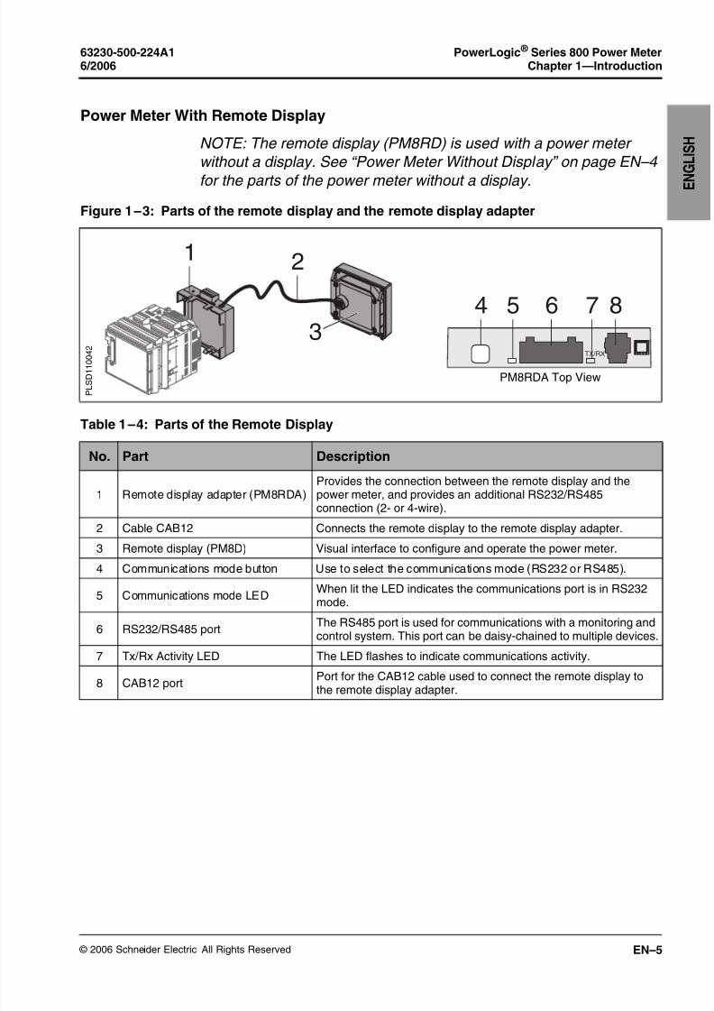
Power Meter With Remote Display
NOTE: The remote display (PM8RD) is used with a power meter
without a display. See “Power Meter Without Display” on page EN–4
for the parts of the power meter without a display.
Figure 1 – 3: Parts of the remote display and the remote display adapter
2
3
1
TX/RX
4 5 6 87
P L S D 1 1 0 0 4
2
PM8RDA Top View
Table 1 – 4: Parts of the Remote Display
No. Part Description
1 Remote display adapter (PM8RDA)Provides the connection between the remote display and thepower meter, and provides an additional RS232/RS485connection (2- or 4-wire).
2 Cable CAB12 Connects the remote display to the remote display adapter.
3 Remote display (PM8D) Visual interface to configure and operate the power meter.
4 Communications mode button Use to select the communications mode (RS232 or RS485).
5 Communications mode LEDWhen lit the LED indicates the communications port is in RS232mode.
6 RS232/RS485 portThe RS485 port is used for communications with a monitoring andcontrol system. This port can be daisy-chained to multiple devices.
7 Tx/Rx Activity LED The LED flashes to indicate communications activity.
8 CAB12 portPort for the CAB12 cable used to connect the remote display tothe remote display adapter.

8/2/2019 Medidor Electrico Analizador de Redes Pm800 Shneider
http://slidepdf.com/reader/full/medidor-electrico-analizador-de-redes-pm800-shneider 12/72
© 2006 Schneider Electric All Rights Reserved
PowerLogic ® Series 800 Power Meter 63230-500-224A1Chapter 1—Introduction 6/2006
EN–6
E N G L
I S H
Power Meter Parts and Accessories
Table 1 – 5: Power Meter Parts and Accessories
DescriptionModel Number
Square D Merlin Gerin
Power Meters
Power Meter with Integrated Display
PM820➀
PM850➁
PM870➂
PM820MG➀
PM850MG➁
PM870MG➂
Power Meter without Display
PM820U➀
PM850U➁
PM870U➂
PM820UMG➀
PM850UMG➁
PM870UMG➂
Power Meter with Remote Display
PM820RD➀
PM850RD➁
PM870RD➂
PM820RDMG➀
PM850RDMG➁
PM870RDMG➂
Accessories
Remote Display with Remote DisplayAdapter PM8RD PM8RDMG
Remote Display Adapter PM8RDA
Input/Output Modules PM8M22, PM8M26, PM8M2222
Cable (12 inch) Extender Kit fordisplays
RJ11EXT
Retrofit Gasket (for 4 in. round holemounting) PM8G
CM2000 Retrofit Mounting Adapter PM8MA
➀ The Power Meter units for these models are identical and support the same features (see “Features” onpage EN–8).
➁ The Power Meter units for these models are identical and support the same features (see “Features” onpage EN–8).
➂ The Power Meter units for these models are identical and support the same features (see “Features” onpage EN–8).
8/2/2019 Medidor Electrico Analizador de Redes Pm800 Shneider
http://slidepdf.com/reader/full/medidor-electrico-analizador-de-redes-pm800-shneider 13/72
© 2006 Schneider Electric All Rights Reserved
63230-500-224A1 PowerLogic ® Series 800 Power Meter6/2006 Chapter 1—Introduction
EN–7
E N
G L I S H
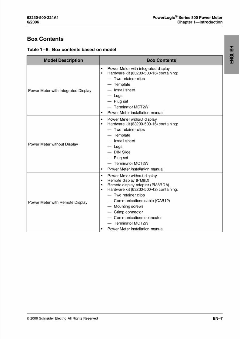
Box Contents
Table 1 – 6: Box contents based on model
Model Description Box Contents
Power Meter with Integrated Display
• Power Meter with integrated display• Hardware kit (63230-500-16) containing:
— Two retainer clips
— Template
— Install sheet
— Lugs
— Plug set
— Terminator MCT2W
• Power Meter installation manual
Power Meter without Display
• Power Meter without display• Hardware kit (63230-500-16) containing:
— Two retainer clips
— Template
— Install sheet
— Lugs
— DIN Slide
— Plug set
— Terminator MCT2W
• Power Meter installation manual
Power Meter with Remote Display
• Power Meter without display• Remote display (PM8D)• Remote display adapter (PM8RDA)• Hardware kit (63230-500-42) containing:
— Two retainer clips
— Communications cable (CAB12)
— Mounting screws
— Crimp connector
— Communications connector
— Terminator MCT2W
• Power Meter installation manual

8/2/2019 Medidor Electrico Analizador de Redes Pm800 Shneider
http://slidepdf.com/reader/full/medidor-electrico-analizador-de-redes-pm800-shneider 14/72
© 2006 Schneider Electric All Rights Reserved
PowerLogic ® Series 800 Power Meter 63230-500-224A1Chapter 1—Introduction 6/2006
EN–8
E N G L
I S H
Features
Table 1 – 7: Series 800 Power Meter Features
PM820 PM850 PM870
True rms metering to the 63rd harmonic
Accepts standard CT and PT inputs
600 volt direct connection on voltage inputs
High accuracy — 0.075% current and voltage (typical conditions)
Min/max readings of metered data
Input metering (five channels) with PM8M22, PM8M26, or PM8M2222installed
Power quality readings — THD
Downloadable firmware
Easy setup through the integrated or remote display (password protected)
Setpoint-controlled alarm and relay functions
Onboard alarm logging
Wide operating temperature range: –25° to +70°C for the power meterunit
Communications:
Onboard: one Modbus RS485 (2-wire)
PM8RD: one configurable Modbus RS232/RS485 (2- or 4-wire)
Active energy accuracy: IEC 62053-22 and ANSI C12.20 Class 0.5S
Nonvolatile clock
Onboard data logging 80 KB 800 KB 800 KB
Real-time harmonic magnitudes and angles (I and V):
To the 31st harmonic
To the 63rd harmonic
—
—
—
Waveform capture
Standard
Advanced
—
—
—
EN50160 evaluations —
Current and voltage sag/swell detection and logging — —

8/2/2019 Medidor Electrico Analizador de Redes Pm800 Shneider
http://slidepdf.com/reader/full/medidor-electrico-analizador-de-redes-pm800-shneider 15/72
© 2006 Schneider Electric All Rights Reserved
63230-500-224A1 PowerLogic ® Series 800 Power Meter6/2006 Chapter 1—Introduction
EN–9
E N
G L I S H
Firmware
This instruction bulletin is written to be used with firmware version
10.5. See “Identifying the Firmware Version” on page EN–56 for
instructions on how to determine the firmware version. To downloadthe latest firmware version, follow the steps below:
1. Using a web browser, go to http://www.powerlogic.com.
2. Select United States.
3. Click downloads.
4. Enter your login information, then click LogIn.
5. Click PM8 Firmware under the POWERLOGIC section.
6. Follow the instructions on the web page that explains how to
download and install the new firmware.

8/2/2019 Medidor Electrico Analizador de Redes Pm800 Shneider
http://slidepdf.com/reader/full/medidor-electrico-analizador-de-redes-pm800-shneider 16/72
© 2006 Schneider Electric All Rights Reserved
PowerLogic ® Series 800 Power Meter 63230-500-224A1Chapter 1—Introduction 6/2006
EN–10
E N G L
I S H

8/2/2019 Medidor Electrico Analizador de Redes Pm800 Shneider
http://slidepdf.com/reader/full/medidor-electrico-analizador-de-redes-pm800-shneider 17/72
© 2006 Schneider Electric All Rights Reserved
63230-500-224A1 PowerLogic ® Series 800 Power Meter6/2006 Chapter 2—Safety Precautions
EN–11
E N
G L I S H
CHAPTER 2—SAFETY PRECAUTIONS
DANGERHAZARD OF ELECTRIC SHOCK, BURN, OR ARC FLASH
• Apply appropriate personal protective equipment (PPE) and follow safe electrical
work practices. For example, in the United States, see NFPA 70E.
• This equipment must only be installed and serviced by qualified electrical
personnel.
• NEVER work alone.
• Before performing visual inspections, tests, or maintenance on this equipment,disconnect all sources of electric power. Assume that all circuits are live until they
have been completely de-energized, tested, and tagged. Pay particular attention to
the design of the power system. Consider all sources of power, including the
possibility of backfeeding.
• Turn off all power supplying this equipment before working on or inside equipment.
• Always use a properly rated voltage sensing device to confirm that all power is off.
• Beware of potential hazards and carefully inspect the work area for tools and
objects that may have been left inside the equipment.
• Use caution while removing or installing panels so that they do not extend into theenergized bus; avoid handling the panels, which could cause personal injury.
• The successful operation of this equipment depends upon proper handling,
installation, and operation. Neglecting fundamental installation requirements may
lead to personal injury as well as damage to electrical equipment or other property.
• NEVER bypass external fusing.
• Before performing Dielectric (Hi-Pot) or Megger testing on any equipment in which
the power meter is installed, disconnect all input and output wires to the power
meter. High voltage testing may damage electronic components contained in the
power meter.
Failure to follow this instruction will result in death or serious injury.

8/2/2019 Medidor Electrico Analizador de Redes Pm800 Shneider
http://slidepdf.com/reader/full/medidor-electrico-analizador-de-redes-pm800-shneider 18/72
© 2006 Schneider Electric All Rights Reserved
PowerLogic ® Series 800 Power Meter 63230-500-224A1Chapter 2—Safety Precautions 6/2006
EN–12
E N G L
I S H

8/2/2019 Medidor Electrico Analizador de Redes Pm800 Shneider
http://slidepdf.com/reader/full/medidor-electrico-analizador-de-redes-pm800-shneider 19/72
© 2006 Schneider Electric All Rights Reserved
63230-500-224A1 PowerLogic ® Series 800 Power Meter6/2006 Chapter 3—Installation
EN–13
E N
G L I S H
CHAPTER 3—INSTALLATION
Installation Considerations
When choosing a mounting location, consider the following points:
• Allow for easy access to all parts of the power meter. Allow extra
space for all wires, fuse disconnects, shorting blocks,
accessories, or other components. Make sure to route the wires
so that they do not cover the back of the unit or cooling vents on
the power meter.
• Install the power meter in a protective enclosure (for example, in
the USA use a NEMA Type 1 rated enclosure or better).
Table 3 – 1: Mounting Summary for Power Meter Models and Accessories
DescriptionModel Number
SectionSquare D Merlin Gerin
Power Meters
Power Meter with IntegratedDisplay
PM820
PM850
PM870
PM820MG
PM850MG
PM870MG
“Dimensions” on page EN–15
“Mounting” on page EN–15
Power Meter without Display
PM820U
PM850U
PM870U
PM820UMG
PM850UMG
PM870UMG
“DIN Rail Mounting” on page EN–20
Power Meter with Remote Display
PM820RD
PM850RD
PM870RD
PM820RDMG
PM850RDMG
PM870RDMG
“PM8RD Dimensions and MountingOptions” on page EN–23
Accessories
Remote Display with Remote
Display AdapterPM8RD PM8RDMG
“PM8RDA Dimensions” on page EN–21
“PM8RD Dimensions and MountingOptions” on page EN–23
Remote Display Adapter PM8RDA
“PM8RDA Dimensions” on page EN–21
“PM8RDA Installation” on page EN–22
Retrofit Gasket (for 4 in. roundcutout mounting)
PM8G “Replacing Analog Meters” onpage EN–18
CM2000 Retrofit Mounting Adapter PM8MA

8/2/2019 Medidor Electrico Analizador de Redes Pm800 Shneider
http://slidepdf.com/reader/full/medidor-electrico-analizador-de-redes-pm800-shneider 20/72
© 2006 Schneider Electric All Rights Reserved
PowerLogic ® Series 800 Power Meter 63230-500-224A1Chapter 3—Installation 6/2006
EN–14
E N G L
I S H
• For European Community (CE) compliance, the disconnect circuit
breaker must be placed within reach of the power meter and
labeled: Disconnect Circuit Breaker for Power Meter.
NOTE: The disconnect circuit breaker must be rated for the short circuit current at the connection points.
• Locate the power meter in an area where ambient conditions fall
within the acceptable range. For control power voltages above
300 Vac, the temperature range for the meter block is -25°C to
+65°C. The front display has a range of -10°C to +50°C.
NOTE: Ambient temperature refers to the immediate environment
of the power meter, including the temperature within the enclosure in which it is mounted.
CAUTION
IMPROPER VENTILATION
• Only mount the power meter as described in this instruction
bulletin.
• Provide the clearances around the power meter as illustrated inFigure 3 – 1, Figure 3 – 2, and Figure 3 – 3.
Failure to follow this instruction can result in equipment damage.
8/2/2019 Medidor Electrico Analizador de Redes Pm800 Shneider
http://slidepdf.com/reader/full/medidor-electrico-analizador-de-redes-pm800-shneider 21/72
© 2006 Schneider Electric All Rights Reserved
63230-500-224A1 PowerLogic ® Series 800 Power Meter6/2006 Chapter 3—Installation
EN–15
E N
G L I S H
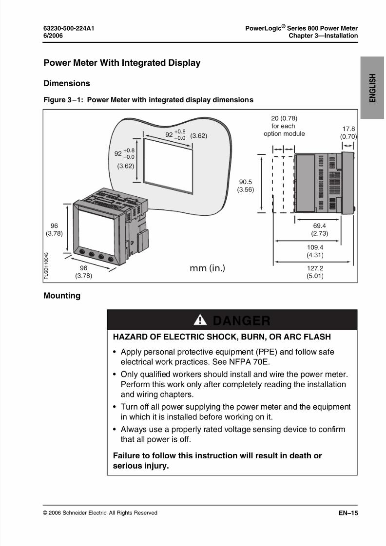
Power Meter With Integrated Display
Dimensions
Mounting
Figure 3 – 1: Power Meter with integrated display dimensions
96(3.78)
96(3.78)
69.4(2.73)
17.8(0.70)
90.5
(3.56)
20 (0.78)for each
option module
127.2(5.01)
109.4(4.31)
92+0.8–0.0
(3.62)
92+0.8–0.0 (3.62)
mm (in.) P L S D 1 1 0 0 4 3
DANGERHAZARD OF ELECTRIC SHOCK, BURN, OR ARC FLASH
• Apply personal protective equipment (PPE) and follow safe
electrical work practices. See NFPA 70E.
• Only qualified workers should install and wire the power meter.
Perform this work only after completely reading the installationand wiring chapters.
• Turn off all power supplying the power meter and the equipment
in which it is installed before working on it.
• Always use a properly rated voltage sensing device to confirm
that all power is off.
Failure to follow this instruction will result in death or
serious injury.

8/2/2019 Medidor Electrico Analizador de Redes Pm800 Shneider
http://slidepdf.com/reader/full/medidor-electrico-analizador-de-redes-pm800-shneider 22/72
© 2006 Schneider Electric All Rights Reserved
PowerLogic ® Series 800 Power Meter 63230-500-224A1Chapter 3—Installation 6/2006
EN–16
E N G L
I S H
Figure 3 – 2: Clearances for mounting a single power meter
20 (0.787)
20 (0.787)
5
(0.197)
5
(0.197)
106 (4.174)
136
(5.354)
P L S D 1 1 0 0 4 7
Figure 3 – 3: Clearances for mounting multiple power meters
mm (in.)
10 (0.39)
92 (3.62)+0.8
–0.0
92
(3.62)
+0.8
–0.0
HORIZONTAL
P L S D 1 1 0 0 4 5
mm (in)
40
(1.57)
92 (3.62)+0.8
–0.0
92
(3.62)
+0.8
–0.0
VERTICAL
P L S D 1 1 0 0 4 6

8/2/2019 Medidor Electrico Analizador de Redes Pm800 Shneider
http://slidepdf.com/reader/full/medidor-electrico-analizador-de-redes-pm800-shneider 23/72
© 2006 Schneider Electric All Rights Reserved
63230-500-224A1 PowerLogic ® Series 800 Power Meter6/2006 Chapter 3—Installation
EN–17
E N
G L I S H
Mounting a Power Meter with an Integrated Display
1. Refer to “Installation Considerations” on
page EN–13, “Dimensions” on page EN–15,
and “Mounting” on page EN–15.
2. Using the template included with the power
meter, make a square cut-out 3.622 in. x 3.622
in. (92 mm x 92 mm).
3. Insert the power meter through the cut-out.
4. Attach the two retainer clips to the power meter
as shown.
There are two sets of retainer slots. The first set
is for installation locations thinner than 1/8 in. (3mm). The second set is for installation locations
1/8 in. to 1/4 in. (3 to 6 mm).
NOTE: Use on a flat surface of a protective
enclosure (for example, in the USA use a NEMA
Type 1 rated enclosure or better).
3
<1/ 8
3 to 6
(1/ 8 to 1/4)
mm (in.)

8/2/2019 Medidor Electrico Analizador de Redes Pm800 Shneider
http://slidepdf.com/reader/full/medidor-electrico-analizador-de-redes-pm800-shneider 24/72
© 2006 Schneider Electric All Rights Reserved
PowerLogic ® Series 800 Power Meter 63230-500-224A1Chapter 3—Installation 6/2006
EN–18
E N G L
I S H
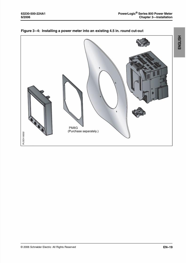
Replacing Analog Meters
1. Refer to “Installation Considerations” on page EN–13,
“Dimensions” on page EN–15, and “Mounting” on page EN–15.
2. Remove the original meter. Refer to the meter’s documentation
for instructions.
NOTE: After removing the original meter, you should have a 4 in.
round cut-out. The power meter will be inserted into this opening.
3. Ground yourself and discharge any static charge.
4. Remove the display from the power meter.
a. Insert a screwdriver into the engraved slot of one of the clips
on the display.
b. Gently, but firmly pull the screwdriver towards the front of thepower meter display until the clip releases. Be sure to hold the
display to keep the clip from reattaching.
c. Repeat steps 3a and 3b to release the adjacent clip and the
clips on the other side.
d. Gently pull the display off of the power meter.
5. Place the power meter behind the round cut-out.
6. Replace the display onto the power meter. The clips on the top
and bottom of the display will securely snap into place.
7. Attach the two retainer clips to the power meter.
CAUTION
ESD-SENSITIVE EQUIPMENT
You must ground yourself and discharge any static charge before
removing or attaching the display.
Failure to follow this instruction can result in equipment damage.
8/2/2019 Medidor Electrico Analizador de Redes Pm800 Shneider
http://slidepdf.com/reader/full/medidor-electrico-analizador-de-redes-pm800-shneider 25/72
© 2006 Schneider Electric All Rights Reserved
63230-500-224A1 PowerLogic ® Series 800 Power Meter6/2006 Chapter 3—Installation
EN–19
E N
G L I S H
Figure 3 – 4: Installing a power meter into an existing 4.5 in. round cut-out
PM8G
P L S D 1 1 0 0 3 2 (Purchase separately.)

8/2/2019 Medidor Electrico Analizador de Redes Pm800 Shneider
http://slidepdf.com/reader/full/medidor-electrico-analizador-de-redes-pm800-shneider 26/72
© 2006 Schneider Electric All Rights Reserved
PowerLogic ® Series 800 Power Meter 63230-500-224A1Chapter 3—Installation 6/2006
EN–20
E N G L
I S H
Power Meter Without Display
DIN Rail Mounting
1. Refer to “Installation Considerations” on
page EN–13.
2. Place the power meter so that the slot in the
base rests on one edge of the DIN rail and
snap it into place securely.
NOTE: DIN rail mounting is only used to install
power meters that do not have displays (see
Table 1 – 5 on page EN–6 for a list of models).
P L S D 1 1 0 0 3

8/2/2019 Medidor Electrico Analizador de Redes Pm800 Shneider
http://slidepdf.com/reader/full/medidor-electrico-analizador-de-redes-pm800-shneider 27/72
© 2006 Schneider Electric All Rights Reserved
63230-500-224A1 PowerLogic ® Series 800 Power Meter6/2006 Chapter 3—Installation
EN–21
E N
G L I S H
Power Meter With Remote Display
This section explains how to install a remote display and a remote
display adapter. A Power Meter without a display (PM8XXU models)
can be used with a remote display kit (PM8RD).
PM8RDA Dimensions
NOTE: Refer to “Installation Considerations” on page EN–13,
“Dimensions” on page EN–15, and “Mounting” on page EN–15 for
additional information
Figure 3 – 5: PM8RDA Dimensions
111[4.382]
132[5.236]
91[3.600]
112[4.409]
91[3.569]
A
B DC
mm[in]
A. 35 mm DIN railB. Option modulesC. Power Meter without
displayD. Remote display
adapter (PM8RDA)
8/2/2019 Medidor Electrico Analizador de Redes Pm800 Shneider
http://slidepdf.com/reader/full/medidor-electrico-analizador-de-redes-pm800-shneider 28/72
© 2006 Schneider Electric All Rights Reserved
PowerLogic ® Series 800 Power Meter 63230-500-224A1Chapter 3—Installation 6/2006
EN–22
E N G L
I S H
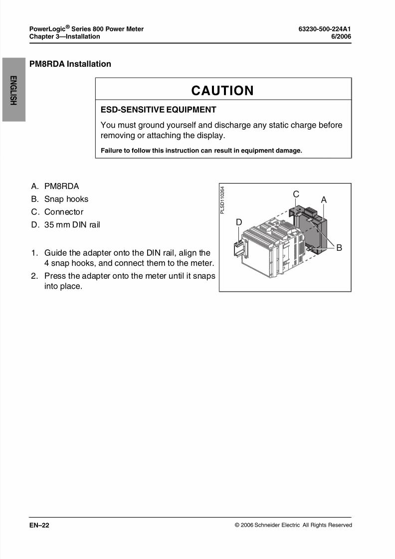
PM8RDA Installation
CAUTION
ESD-SENSITIVE EQUIPMENT
You must ground yourself and discharge any static charge before
removing or attaching the display.
Failure to follow this instruction can result in equipment damage.
A. PM8RDA
B. Snap hooks
C. Connector
D. 35 mm DIN rail
1. Guide the adapter onto the DIN rail, align the
4 snap hooks, and connect them to the meter.
2. Press the adapter onto the meter until it snaps
into place.
B
C A
D
P L S D 1 1 0
2 6 4

8/2/2019 Medidor Electrico Analizador de Redes Pm800 Shneider
http://slidepdf.com/reader/full/medidor-electrico-analizador-de-redes-pm800-shneider 29/72
© 2006 Schneider Electric All Rights Reserved
63230-500-224A1 PowerLogic ® Series 800 Power Meter6/2006 Chapter 3—Installation
EN–23
E N
G L I S H
PM8RD Dimensions and Mounting Options
NOTE: Refer to “Installation Considerations” on page EN–13,
“Dimensions” on page EN–15, and “Mounting” on page EN–15 for additional information
Square Cutout
DANGERHAZARD OF ELECTRIC SHOCK, BURN, OR ARC FLASH
• Apply personal protective equipment (PPE) and follow safe
electrical work practices. For example, in the USA, see NFPA
70E.
• Only qualified workers should install and wire the power meter.Perform this work only after completely reading the installation
and wiring chapters.
• Turn off all power supplying the power meter and the equipment
in which it is installed before working on it.
• Always use a properly rated voltage sensing device to confirm
that all power is off.
Failure to follow this instruction will result in death or
serious injury.
92
(3.622)
92
(3.622)
12
(0.457)
96
(3.780)
21
(0.839)
19
(0.751)
mm(in)

8/2/2019 Medidor Electrico Analizador de Redes Pm800 Shneider
http://slidepdf.com/reader/full/medidor-electrico-analizador-de-redes-pm800-shneider 30/72
© 2006 Schneider Electric All Rights Reserved
PowerLogic ® Series 800 Power Meter 63230-500-224A1Chapter 3—Installation 6/2006
EN–24
E N G L
I S H
Surface Mount for CM3000/CM4000 Display Retrofit
Replacing Analog Meters
76
[3.000]
54
[2.125]
27
[1.063]
13 [0.500]
4 x Ø4
[Ø0.157]
Ø22 (Ø32 max)
[Ø0.880]96
[3.780]
10
[0.394]
82
[3.230]
31
[1.220]mm[in]
mm[in]
4 x Ø4
[Ø0.157]
86
[3.376]
86
[3.376]
Ø102
[Ø4.000]
12
[0.457]
96
[3.780]
21
[0.839]
82
[3.230]
19
[0.751]
PM8G

8/2/2019 Medidor Electrico Analizador de Redes Pm800 Shneider
http://slidepdf.com/reader/full/medidor-electrico-analizador-de-redes-pm800-shneider 31/72
© 2006 Schneider Electric All Rights Reserved
63230-500-224A1 PowerLogic ® Series 800 Power Meter6/2006 Chapter 4—Wiring
EN–25
E N
G L I S H
CHAPTER 4—WIRING
Introduction
This chapter explains how to make the wiring connections for the
power meter.
The following symbols are used in the diagrams:
NOTE: The disconnect circuit breaker must be placed within reach of
the power meter and labeled: Disconnect Circuit Breaker for Power Meter .
Table 4 – 1: Wiring Diagram Symbols
Symbol Description
Voltage disconnect switch
Fuse
Earth ground
Current transformer
Shorting block
Potential transformer
US equivalent:
S2
S1
8/2/2019 Medidor Electrico Analizador de Redes Pm800 Shneider
http://slidepdf.com/reader/full/medidor-electrico-analizador-de-redes-pm800-shneider 32/72
© 2006 Schneider Electric All Rights Reserved
PowerLogic ® Series 800 Power Meter 63230-500-224A1Chapter 4—Wiring 6/2006
EN–26
E N G L
I S H
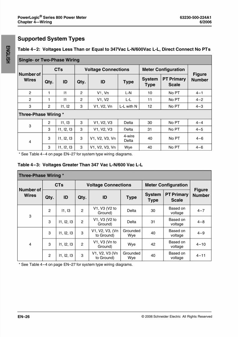
Supported System Types
Table 4 – 2: Voltages Less Than or Equal to 347Vac L-N/600Vac L-L, Direct Connect No PTs
Single- or Two-Phase Wiring
Number of
Wires
CTs Voltage Connections Meter ConfigurationFigure
NumberQty. ID Qty. ID TypeSystem
Type
PT Primary
Scale
2 1 I1 2 V1, Vn L-N 10 No PT 4 – 1
2 1 I1 2 V1, V2 L-L 11 No PT 4 – 2
3 2 I1, I2 3 V1, V2, Vn L-L with N 12 No PT 4 – 3
Three-Phase Wiring *
32 I1, I3 3 V1, V2, V3 Delta 30 No PT 4 – 4
3 I1, I2, I3 3 V1, V2, V3 Delta 31 No PT 4 – 5
43 I1, I2, I3 3 V1, V2, V3, Vn
4-wireDelta
40 No PT 4 – 6
3 I1, I2, I3 3 V1, V2, V3, Vn Wye 40 No PT 4 – 6
* See Table 4 – 4 on page EN–27 for system type wiring diagrams.
Table 4 – 3: Voltages Greater Than 347 Vac L-N/600 Vac L-L
Three-Phase Wiring *
Number of
Wires
CTs Voltage Connections Meter ConfigurationFigure
NumberQty. ID Qty. ID TypeSystem
Type
PT Primary
Scale
3
2 I1, I3 2V1, V3 (V2 to
Ground)Delta 30
Based onvoltage
4 – 7
3 I1, I2, I3 2V1, V3 (V2 to
Ground)Delta 31
Based onvoltage
4 – 8
4
3 I1, I2, I3 3V1, V2, V3, (Vn
to Ground)
Grounded
Wye40
Based on
voltage4 – 9
3 I1, I2, I3 2V1, V3 (Vn to
Ground)Wye 42
Based onvoltage
4 – 10
2 I1, I2, I3 3V1, V2, V3 (Vn
to Ground)Grounded
Wye40
Based onvoltage
4 – 11
* See Table 4 – 4 on page EN–27 for system type wiring diagrams.

8/2/2019 Medidor Electrico Analizador de Redes Pm800 Shneider
http://slidepdf.com/reader/full/medidor-electrico-analizador-de-redes-pm800-shneider 33/72
© 2006 Schneider Electric All Rights Reserved
63230-500-224A1 PowerLogic ® Series 800 Power Meter6/2006 Chapter 4—Wiring
EN–27
E N
G L I S H
Table 4 – 4: System Type Wiring Diagrams
Diagram System Type
Delta
4-wire Delta
Wye
Grounded Wye
NOTE: In 2 PT systems, these connections are equivalent.
N
L1
L2
L3
V1
V2
V3
L1
L2
L3
V1
V2
V3

8/2/2019 Medidor Electrico Analizador de Redes Pm800 Shneider
http://slidepdf.com/reader/full/medidor-electrico-analizador-de-redes-pm800-shneider 34/72
© 2006 Schneider Electric All Rights Reserved
PowerLogic ® Series 800 Power Meter 63230-500-224A1Chapter 4—Wiring 6/2006
EN–28
E N G L
I S H
Wiring Diagrams
DANGERHAZARD OF ELECTRIC SHOCK, BURN, OR ARC FLASH
• Apply appropriate personal protective equipment (PPE) and
follow safe electrical work practices. For example, in the United
States, see NFPA 70E.
• This equipment must only be installed and serviced by qualified
electrical personnel.
• Perform this work only after completely reading the installation
and wiring chapters.
• Turn off all power supplying the power meter and the equipment
in which it is installed before working on it.
• Always use a properly rated voltage sensing device to verify that
the power is off.
• Never short the secondary of a PT.
• Never open circuit a CT; use the shorting block to short circuit the
leads of the CT before removing the connection from the power
meter.
Failure to follow these instructions will result in death or
serious injury.

8/2/2019 Medidor Electrico Analizador de Redes Pm800 Shneider
http://slidepdf.com/reader/full/medidor-electrico-analizador-de-redes-pm800-shneider 35/72
© 2006 Schneider Electric All Rights Reserved
63230-500-224A1 PowerLogic ® Series 800 Power Meter6/2006 Chapter 4—Wiring
EN–29
E N
G L I S H
Figure 4 – 1: 1-Phase Line-to-Neutral 2-WireSystem 1 CT
Figure 4 – 2: 2-Phase Line-to-Line 2-Wire System1 CT
NOTES:
• To avoid distortion, use parallel wires for controlpower and voltage inputs. Keep the fuse close tothe power source.
• Use system type 10.
NOTES:
• To avoid distortion, use parallel wires for controlpower and voltage inputs. Keep the fuses close tothe power source.
• Use system type 11.
Figure 4 – 3: 2-Phase 3-Wire Direct VoltageConnection 2 CT
Figure 4 – 4: 3-Phase 3-Wire 2 CT no PT
NOTE:
• To avoid distortion, use parallel wires for controlpower and voltage inputs. Keep the fuses close tothe power source.
• Use system type 12.
NOTES:
• Use system type 30.
N L1
PM800
8
9
10
11
12
1314
15
1617
S2
S1
P L S D 1 1 0 0 5 1
PM800
L1 L2
8
9
10
11
12
1314
15
16
17
VL-L=< 600V
S2
S1
P L S D 1 1 0 0 5 0
L1 L2N
PM800
8
9
10
11
12
1314
15
16
17
S2
S1
S2
S1
P L S D 1 1 0 0 4 9
L 1 L 2 L 3
PM800
8
9
10
11
12
1314
15
16
17
S2
S1
S2
S1
P L S D 1 1 0 0 5 4

8/2/2019 Medidor Electrico Analizador de Redes Pm800 Shneider
http://slidepdf.com/reader/full/medidor-electrico-analizador-de-redes-pm800-shneider 36/72
© 2006 Schneider Electric All Rights Reserved
PowerLogic ® Series 800 Power Meter 63230-500-224A1Chapter 4—Wiring 6/2006
EN–30
E N G L
I S H
Figure 4 – 5: 3-Phase 3-Wire 3 CT no PT Figure 4 – 6: 3-Phase 4-Wire Wye Direct VoltageInput Connection 3 CT
NOTES:
• Use system type 31.
NOTES:
• Use with 480Y/277 V and 208Y/120 V systems.• Use system type 40.
Figure 4 – 7: 3-Phase 3-Wire Delta Connection 2CT 2 PT
Figure 4 – 8: 3-Phase 3-Wire Delta Connection3CT 2PT
NOTES:
• For an open delta PT connection with 120 V L-Lsecondaries, use system type 30.
• Pay close attention to polarity marks whenconnecting CTs (S1, S2) and PTs ( =X1).
NOTES:
• Use System type 31.• For an open delta PT connection with 120 V L-L
secondaries, use system type 31.• Pay close attention to polarity marks when
connecting CTs (S1, S2) and PTs ( =X1).
L1 L2 L3
PM800
8
9
10
11
12
1314
15
16
17
S2
S1
S2
S1
S2
S1
P L S D 1 1 0 0 5 3
L1 L2 L3N
PM800
8
9
10
11
12
13
14
15
16
17
VL-L=<600V
S2
S1
S2
S1
S2
S1
P L S D 1 1 0 0 5 9
L1 L2 L3
PM800
8
9
10
11
12
1314
15
16
17
S2
S1
S2
S1
P L S D 1 1 0 0 5 5
L1 L2 L3
PM800
8
9
10
11
12
1314
15
16
17
S2
S1
S2
S1
S2
S1
P L S D 1 1 0 0 5 6

8/2/2019 Medidor Electrico Analizador de Redes Pm800 Shneider
http://slidepdf.com/reader/full/medidor-electrico-analizador-de-redes-pm800-shneider 37/72
© 2006 Schneider Electric All Rights Reserved
63230-500-224A1 PowerLogic ® Series 800 Power Meter6/2006 Chapter 4—Wiring
EN–31
E N
G L I S H
Figure 4 – 9: 3-Phase 4-Wire Wye Connection 3CT 3 PT
Figure 4 – 10: 3-Phase 4-Wire Wye 3CT 2PT (forbalanced voltage)
NOTES:
• Use system type 40.• Pay close attention to polarity marks when
connecting CTs (S1, S2) and PTs ( =X1).
NOTES:
• Use system type 42.• Pay close attention to polarity marks when
connecting CTs (S1, S2) and PTs ( =X1).
Figure 4 – 11: 3-Phase 4-Wire Wye 3-wire 3 PT 2CT (for balanced 3-wire loads)
NOTES:
• Use system type 40.• Neutral current readings will be reported as zero.• Pay close attention to polarity marks when
connecting CTs (S1, S2) and PTs ( =X1).
8
9
10
11
12
1314
15
1617
PM800
S2
S1
S2
S1
S2
S1
L1 L2 L3
N
P L S D 1 1 0 0 6 0
L1 L2 L3
N
PM800
8
9
10
11
12
1314
15
16
17
S2
S1
S2
S1
S2
S1
P L S D 1 1 0 0 5 8
PM800
8
9
10
11
12
1314
15
16
17
S2
S1
S2
S1
L1 L2 L3N
P L S D 1 1 0 0 5 7

8/2/2019 Medidor Electrico Analizador de Redes Pm800 Shneider
http://slidepdf.com/reader/full/medidor-electrico-analizador-de-redes-pm800-shneider 38/72
© 2006 Schneider Electric All Rights Reserved
PowerLogic ® Series 800 Power Meter 63230-500-224A1Chapter 4—Wiring 6/2006
EN–32
E N G L
I S H
Figure 4 – 12: Direct Connect Control Power(Phase to Phase)
Figure 4 – 13: Direct Connect Control Power(Phase to Neutral)
Figure 4 – 14: Direct Connect Control Power (DCControl Power)
Figure 4 – 15: Control Power TransformerConnection
L1 L2 L3
8
9
10
11
1 2 3
PM800
Phase to Phase only whenvoltage<415 ± 10 % VAC max.
P L S D 1 1 0 0 7 2
L1L2L3N
8
9
10
11
1 2 3
PM800
Phase to Neutral only whenvoltage<415± 10 % VAC max.
P L S
D 1 1 0 0 7 1
8
9
10
11
1 2 3
DC Control Power100 Vdc < V < 300 Vdc
P L S D 1 1 0 0 6 5
L1 L2 L3N
CPT
8
9
10
11
1 23
PM800
Control Power Transformer120 or 240 Vac Secondary 50 Va max.
P L S D 1 1 0 0 7 0
Table 4 – 5: Fuse Recommendation
Control Power Source Source Voltage (Vs) Fuse Fuse Amperage
CPT Vs ≤125 V FNM or MDL 250 mA
CPT 125 < Vs ≤240 V FNQ or FNQ-R 250 mA
CPT 240 < Vs ≤305 V FNQ or FNQ-R 250 mA
Line Voltage Vs ≤240 V FNQ-R 250 mA
Line Voltage Vs > 240 V FNQ-R 250 mA
DC Vs ≤300 V LP-CC 500 mA
The voltage input protection devices must be rated for the short circuit current at the connection points.

8/2/2019 Medidor Electrico Analizador de Redes Pm800 Shneider
http://slidepdf.com/reader/full/medidor-electrico-analizador-de-redes-pm800-shneider 39/72
© 2006 Schneider Electric All Rights Reserved
63230-500-224A1 PowerLogic ® Series 800 Power Meter6/2006 Chapter 4—Wiring
EN–33
E N
G L I S H
Switching of inductive devices such as relay coils and motors results
in high voltage transients from back electromotive force (EMF). To
monitor this type of circuit, use an isolated power supply, such as the
24 Vdc power supply included with the PM8M26, and an auxiliary
contact on the circuit breaker or switch.
Figure 4 – 16: Standard Input/Output Wiring
8
9
10
11
Y C
PM800
K 1S1
Load
≤ 100 mA
~=
≤ 100 mA
Power Source
3 - 250 Vdc6 - 220 Vac
Power Source24 - 125 Vdc / Vac
Status Switch orAuxiliary Contact
Digital Output / Pulse OutputKY is a solid state pulse output
rated for 250 VDC max. or220 Vac max.
Maximum load current is 100 mAat 25°C. Derate 0.56 mA per °Cabove 25°C.
Digital Input / Status Input / Pulse InputC1 is the common or voltage reference.
S1 is the status input signal.
Overcurrent Protective Device(not supplied)
~=
NOTE: The overc u rrent protective device
m us t b e r a ted for the s hort circ u it c u rrent a t the connection point.
CAUTIONVOLTAGE TRANSIENTS OVER 500 V CAN DAMAGE DIGITAL
INPUTS
• Do not use digital inputs to directly monitor circuits with highly
inductive loads.
• Use auxiliary contacts and isolated power supply when
monitoring inductive loads.
Failure to follow this instruction will result in equipment
damage.

8/2/2019 Medidor Electrico Analizador de Redes Pm800 Shneider
http://slidepdf.com/reader/full/medidor-electrico-analizador-de-redes-pm800-shneider 40/72
© 2006 Schneider Electric All Rights Reserved
PowerLogic ® Series 800 Power Meter 63230-500-224A1Chapter 4—Wiring 6/2006
EN–34
E N G L
I S H

8/2/2019 Medidor Electrico Analizador de Redes Pm800 Shneider
http://slidepdf.com/reader/full/medidor-electrico-analizador-de-redes-pm800-shneider 41/72
© 2006 Schneider Electric All Rights Reserved
63230-500-224A1 PowerLogic ® Series 800 Power Meter6/2006 Chapter 5—Communications
EN–35
E N
G L I S H
CHAPTER 5—COMMUNICATIONS
Onboard Communications Capabilities
Table 5 – 1: 2-wire, RS485 Port Capabilities
Communications Port
RS485:
• 2-wire with shield• EIA compliant• Allows the power meter to be
connected to a daisy-chain of up to 32devices
Baud Rate
9600
19200
38400
Communications Distances See Table 5 – 2.
Protocols
Modbus RTU
Jbus
7-, 8-bit ASCII
Parity
ODD
EVEN
NONE
Table 5 – 2: 2-wire, RS485 Communications Distances
Baud Rate
Maximum Communication Distances
1 to 32 Devices
Feet Meters
9600 8,000 2,438
19200 6,000 1,829
38400 3,000 914
NOTES: • Distances are for 2-wire devices and 4-wire devices configured for 2-wire operation,
such as the Series 600 Power Meter and the Series 3000 and 4000 Circuit Monitor.• Distances listed should be used as a guide only and cannot be guaranteed for non-
POWERLOGIC devices. Refer to the master device’s documentation for anyadditional distance limitations.

8/2/2019 Medidor Electrico Analizador de Redes Pm800 Shneider
http://slidepdf.com/reader/full/medidor-electrico-analizador-de-redes-pm800-shneider 42/72
© 2006 Schneider Electric All Rights Reserved
PowerLogic ® Series 800 Power Meter 63230-500-224A1Chapter 5—Communications 6/2006
EN–36
E N G L
I S H
Daisy-chaining Devices to the Power Meter
The RS485 slave port allows the power meter to be connected in a
daisy chain with up to 31, 2-wire devices. In this bulletin,
communications link refers to a chain of devices that are connected
by a communications cable.
To daisy-chain devices to the power meter, use communications
cable containing a twisted-shielded pair (Belden 9841 or equivalent)
and the three-terminal connector of the RS485 port on the power
meter.To connect to the power meter, follow these steps:
1. Strip 0.25 in. (6 mm) of insulation from both ends of the cable
wires and insert one end into the holes in the connector.
2. On the top of the connector, torque the wire binding screws 5–7
in-lb (0.56–0.79 N•m).
Figure 5 – 1: Power meters with integrated displays connected to a PC serial port through
the onboard 2-wire RS485 port
Belden 9841(or equivalent
cable)
1 to 32 power meters
Host
RS232/485Modbus RTU 2-wire converter
P L S D 1 1 0 0 8 3
Figure 5 – 2: RS485 connection
–+
18
19
20
Silver
White with blue
stripe
Blue with white
stripePLSD110085
0.56–0.79 N•m

8/2/2019 Medidor Electrico Analizador de Redes Pm800 Shneider
http://slidepdf.com/reader/full/medidor-electrico-analizador-de-redes-pm800-shneider 43/72
© 2006 Schneider Electric All Rights Reserved
63230-500-224A1 PowerLogic ® Series 800 Power Meter6/2006 Chapter 5—Communications
EN–37
E N
G L I S H
2-wire Devices
To daisy-chain the power meter to another 2-wire POWERLOGIC
device, wire the power meter’s RS485 communications terminals to
the matching communications terminals of the next device. In otherwords, wire the + terminal of the power meter to the + terminal of the
next device, wire – to –, and shield to shield as shown in Figure 5 – 3.
• If the power meter is the first device on the daisy chain, connect itto the host device using the MCI-101 kit (or equivalent RS232 to
RS422/RS485 converter). See “Connecting the First Device” on
page EN–38 in this chapter for instructions.
• If the power meter is the last device on the daisy chain, terminate
it. See “Terminating the Communications Link” on page EN–38 in
this chapter for instructions.
• See Table 5 – 2 on page EN–35 for the maximum daisy-chain
communications distances for 2-wire devices.
4-wire Devices for 2-wire Modbus or Jbus
When wiring Modbus 4-wire communications terminals for 2-wire
Modbus or Jbus, jumper RX+ to TX+ and RX– to TX– as shown in
Figure 5 – 4.
Figure 5 – 3: Daisy-chaining 2-wire devices
–+
Power Meter 800 or other POWERLOGIC 2-wire compatible devices
Belden 9841 or equivalent
Belden 9841 wire colors: blue with white stripe (+), white with blue stripe (–), and silver (shield)
MCT2W terminator onthe last device of the
daisy chain
P L S D 1 1 0 0 8 7

8/2/2019 Medidor Electrico Analizador de Redes Pm800 Shneider
http://slidepdf.com/reader/full/medidor-electrico-analizador-de-redes-pm800-shneider 44/72
© 2006 Schneider Electric All Rights Reserved
PowerLogic ® Series 800 Power Meter 63230-500-224A1Chapter 5—Communications 6/2006
EN–38
E N G L
I S H
Connecting the First Device
If the power meter is the first device on the daisy chain, refer to Figure
5 – 4.
Terminating the Communications Link
For proper RS485 communications performance, you must terminate
the last device on the communications link using the MCT2W
terminator, which inserts directly into the connector in the RS485 port
of the power meter as illustrated in Figure 5 – 3 on page EN–37.
NOTES :
• Terminate only the last device on the link. If a link has only one
device, terminate that device.
• Some POWERLOGIC devices use a removable communications
connector. If the last device on the communications link is not a
power meter, refer to the instruction bulletin for that device for
termination instructions.
Using the MCT2W Terminator
To terminate the power meter using the MCT2W terminator, insert the
wires of the terminator directly into terminals 19 and 20 of the RS485
communications connector on the power meter as shown in Figure
5 – 3.
Figure 5 – 4: Jumpers for 4-wire devices on 2-wire daisy chain
20 RX+
21 RX–
22 TX+
23 TX–
24 SHLD
18
19 –
20 +
Belden 9841 orequivalent
CM3000, CM4000,or PM600
PM800
Jumpers
Belden 8723 or equivalent
From Master(Host) Device
MCT2W
2-wire Mode
NOTE: This only applies to devices that support 2-wire mode. P L S D 1 1 0 0 8 6

8/2/2019 Medidor Electrico Analizador de Redes Pm800 Shneider
http://slidepdf.com/reader/full/medidor-electrico-analizador-de-redes-pm800-shneider 45/72
© 2006 Schneider Electric All Rights Reserved
63230-500-224A1 PowerLogic ® Series 800 Power Meter6/2006 Chapter 5—Communications
EN–39
E N
G L I S H
Connecting to a 4-Wire Daisy Chain (CM2000)
When wiring a power meter to a 4-wire daisy chain supporting a
CM2000, you will need to use a 4- to 2-wire converter.
Figure 5 – 5: Using a 4- to 2-wire converter to connect a PM800 to a CM2000
Notes:
• CM2000 to CNV100:CM2000 (RX+ = Green, RX– = White, TX+ = Red, TX– = Black, Shield = Gray) CNV100 (RX+ = Green, RX– = White, TX+ = Red, TX– = Black, Shield = Gray)
• PS24 to CNV100: + = Red, – = Black• CNV100 to PM800: Shield = Gray, – = White with blue stripe, + = Blue with white stripe
RX+RX– TX+ TX– T X +
T X –
R X +
R X –
S H L D
– + 1
8 1
9 2 0
PM800
CM2000
— +
— + – +
CNV100PS24
Belden 8723 orequivalent
3090MCT485Terminator
MCT2WTerminator
P L S D 1 1 0 0 6 3
(supplied with CNV100)

8/2/2019 Medidor Electrico Analizador de Redes Pm800 Shneider
http://slidepdf.com/reader/full/medidor-electrico-analizador-de-redes-pm800-shneider 46/72
© 2006 Schneider Electric All Rights Reserved
PowerLogic ® Series 800 Power Meter 63230-500-224A1Chapter 5—Communications 6/2006
EN–40
E N G L
I S H
Figure 5 – 6: Connect Power Meters with integrated displays to a 4-wire daisy chain (Series
2000 Circuit Monitor)
2 0 R X +
2 1 R X –
2 2 T X +
2 3 T X –
2 4 S H L D
18
1 9
–
20
+
2 0 R X +
2 1 R X –
2 2 T X
+
2 3 T X
–
2 4 S H L D
18
1 9
–
20
+
o AMMETER(A)
o VOLTMETER,L-L(V)
o VOLTMETER,L-N(V)
o WATTMETER(W)
o VARMETER(VAr)
o VAMETER(VA)
o POWERFACTORMETER
o FREQUENCYMETER(Hz)
o DEMANDAMMETER(A)
o DEMANDPOWER(W)
o DEMANDPOWER(VA)
o WATTHOURMETER
o VARHOURMETER
oTHD,CURRE NT( %)
o THD,VOLTAGE(%)
o K-FACTOR
CIRCUITMONITOR
[CTPrimary]
[PTPrimary]
[Sys.Type]
[Dmd.Int.]
[WH/Pulse]
[Address]
[BaudRate]
[Nom.Freq.]
[Reset]
[Reset]
[Reset]
[Reset]
[Reset]
[Rst.Min/Max]
[SetPassword]
[Accept]
3-PHASE
A(A-B)
B(B-C)
C(C-A)
N
SELECTMETER[Value]
METERS
MIN
MAX
ALARM
[Setup]
Kilo
Mega
PHASE
MODE
Optical
CommPort
®
Kilo
o AMMETER(A)
o VOLTMETER,L-L(V)
o VOLTMETER,L-N(V)
o WATTMETER(W)
o VARMETER(VAr)
o VAMETER(VA)
o POWERFACTORMETER
o FREQUENCYMETER(Hz)
o DEMANDAMMETER(A)
o DEMANDPOWER(W)
o DEMANDPOWER(VA)
o WATTHOURMETER
o VARHOURMETER
oTHD,CURRE NT( %)
o THD,VOLTAGE(%)
o K-FACTOR
CIRCUITMONITOR
[CTPrimary]
[PTPrimary]
[Sys.Type]
[Dmd.Int.]
[WH/Pulse]
[Address]
[BaudRate]
[Nom.Freq.]
[Reset]
[Reset]
[Reset]
[Reset]
[Reset]
[Rst.Min/Max]
[SetPassword]
[Accept]
3-PHASE
A(A-B)
B(B-C)
C(C-A)
N
SELECTMETER[Value]
METERS
MIN
MAX
ALARM
[Setup]
Mega
PHASE
MODE
Optical
CommPort
®
o AMMETER(A)
o VOLTMETER,L-L(V)
o VOLTMETER,L-N(V)
o WATTMETER(W)
o VARMETER(VAr)
o VAMETER(VA)
o POWERFACTORMETER
o FREQUENCYMETER(Hz)
o DEMANDAMMETER(A)
o DEMANDPOWER(W)
o DEMANDPOWER(VA)
o WATTHOURMETER
o VARHOURMETER
oTHD,CURRE NT( %)
o THD,VOLTAGE(%)
o K-FACTOR
CIRCUITMONITOR
[CTPrimary]
[PTPrimary]
[Sys.Type]
[Dmd.Int.]
[WH/Pulse]
[Address]
[BaudRate]
[Nom.Freq.]
[Reset]
[Reset]
[Reset]
[Reset]
[Reset]
[Rst.Min/Max]
[SetPassword]
[Accept]
3-PHASE
A(A-B)
B(B-C)
C(C-A)
N
SELECTMETER[Value]
METERS
MIN
MAX
ALARM
[Setup]
Kilo
Mega
PHASE
MODE
Optical
CommPort
®
—
+
—
+
Belden 8723 orequivalent
3090MCT485Terminator
CNV100 Converter
MCT2WTerminator
CNV-100Converter
MCT2WTerminator
Belden 8723equivalent
Belden 9841 orequivalent
Up to 32PM800s
Up to 32PM800s Belden 9841 or
equivalent
CM2000
PM800
PS24PowerSupply*
IsolatedPS24 PowerSupply*
P L S D 1 1 0 0 6 2
* Included with the CNV100

8/2/2019 Medidor Electrico Analizador de Redes Pm800 Shneider
http://slidepdf.com/reader/full/medidor-electrico-analizador-de-redes-pm800-shneider 47/72
© 2006 Schneider Electric All Rights Reserved
63230-500-224A1 PowerLogic ® Series 800 Power Meter6/2006 Chapter 5—Communications
EN–41
E N
G L I S H
Connecting to an Ethernet Gateway (EGX)
The POWERLOGIC Ethernet Gateway is a network communications
interface that performs protocol conversion between POWERLOGIC-
compatible devices and standard Ethernet network protocols.
An Ethernet Gateway has serial ports that support from 8 to 32
POWERLOGIC devices, depending on the Ethernet Gateway model.
More devices can be daisy-chained when a signal repeater is used.
Refer to the instruction bulletin that ships with your Ethernet Gateway
for more information and installation procedures.
Figure 5 – 7: Power meters connected to Ethernet using a POWERLOGIC Ethernet Gateway
system
Lk
Tx
RxCOM 1 (RS-485)
COM 2 (RS-485)
RS-485
Tx
Rx
Rx-Tx- Tx+
Rx+RS-485 Con f
igura tion
C O M2
C O M 1
COM 2 (RS-232 )
214
7 9 1086
35
24V8W
10 9 8 7 6
+10 / 100 BaseT
5 43 2 1
+
Rx-Tx- Tx+
Rx+
100 Base FX
POWERLOGICNetwork Server
with Client
POWERLOGICEthernet Gateway (EGX)
Ethernet
Belden 9841or equivalent cable
MCT2W Terminator
1–32 Devices (power meters, Series 3000 or4000 Circuit Monitors, or other Modbus or
Jbus compatible devices)
1–32 Devices (power meters, Series 3000 or4000 Circuit Monitors, or other Modbus or
Jbus compatible devices)
MCT2W Terminator
P L S D 1 1 0 0 8 1

8/2/2019 Medidor Electrico Analizador de Redes Pm800 Shneider
http://slidepdf.com/reader/full/medidor-electrico-analizador-de-redes-pm800-shneider 48/72
© 2006 Schneider Electric All Rights Reserved
PowerLogic ® Series 800 Power Meter 63230-500-224A1Chapter 5—Communications 6/2006
EN–42
E N G L
I S H
Power Meter With Remote Display Communications Capabilities
The communications port on the remote display adapter can be
configured to operate as a 2-wire, RS485 port; a 4-wire, RS485 port;
or a RS232 port.
NOTE: The 4-wire, RS485 configuration is useful for integrating
Power Meters into existing 4-wire, RS485 daisy chains because extra
converters (CNV100) are not required.
Table 5 – 3: RS485 Port Capabilities
2-wire 4-wire
Communications Port
• 2-wire with shield
• EIA compliant• Allows the power meter to be
connected to a daisy-chain of upto 32 devices
• 4-wire with shield
• EIA compliant• Allows the power meter to be
connected to a daisy-chain of upto 32 devices
Baud Rate
9600
19200
38400
9600
19200
38400
Communications Distances See Table 5 – 4. See Table 5 – 4.
Protocols
Modbus RTU
Jbus
7-, 8-bit ASCII
Modbus RTU
Jbus
7-, 8-bit ASCII
Parity
ODD
EVEN
NONE
ODD
EVEN
NONE
Table 5 – 4: 2-wire, RS485 Communications Distances
Baud Rate
Maximum Communication Distances
1 to 32 Devices
Feet Meters
9600 8,000 2,438
19200 6,000 1,829
38400 3,000 914
NOTE: Distances listed should be used as a guide only and cannot be guaranteed for non-POWERLOGIC devices. Refer to the master device’s documentation for any additional distance limitations.

8/2/2019 Medidor Electrico Analizador de Redes Pm800 Shneider
http://slidepdf.com/reader/full/medidor-electrico-analizador-de-redes-pm800-shneider 49/72
© 2006 Schneider Electric All Rights Reserved
63230-500-224A1 PowerLogic ® Series 800 Power Meter6/2006 Chapter 5—Communications
EN–43
E N
G L I S H
Power Meter With Remote Display Connections
Table 5 – 5: 4-wire, RS485 Communications Distances
Baud RateMaximum Communication Distances
1 to 16 Devices 17 to 32 Devices
9600 3,048 m (10,000 ft.) 1,219 m (4,000 ft.)
19200 1,548 m (5,000 ft.) 762 m (2,500 ft.)
38400 1,524 m (5,000 ft.) 762 m (2,500 ft.)
NOTE: Distances listed should be used as a guide only and cannot be guaranteed for non-POWERLOGIC devices. Refer to the master device’s documentation for any additional distance limitations.
DANGERHAZARD OF ELECTRIC SHOCK, BURN, OR ARC FLASH
• Apply appropriate personal protective equipment (PPE) and
follow safe electrical work practices. For example, in the United
States, see NFPA 70E.
• This equipment must only be installed and serviced by qualified
electrical personnel.• Perform this work only after completely reading the installation
and wiring chapters.
• Turn off all power supplying the power meter and the equipment
in which it is installed before working on it.
• Always use a properly rated voltage sensing device to verify that
the power is off.
• Never short the secondary of a PT.
• Never open circuit a CT; use the shorting block to short circuit the
leads of the CT before removing the connection from the powermeter.
Failure to follow these instructions will result in death or
serious injury.

8/2/2019 Medidor Electrico Analizador de Redes Pm800 Shneider
http://slidepdf.com/reader/full/medidor-electrico-analizador-de-redes-pm800-shneider 50/72
© 2006 Schneider Electric All Rights Reserved
PowerLogic ® Series 800 Power Meter 63230-500-224A1Chapter 5—Communications 6/2006
EN–44
E N G L
I S H
RS485, 4-wire
RS485, 2-wire
• Use Belden 8723,
9842, or equivalent— RX+ Green, RX-
White— TX+ Red, TX-
Black— Shield Silver (use
crimp connector).
• For Belden 9842
— RX+ Blue/Whitestripe
— RX- White/Bluestripe TX+
Orange/Whitestripe
— TX- White/Orangestripe
• Connect shield to earthground at the masterport only.
• If the display is the lastdevice, terminate itwith 3090MCTAS485terminator (notincluded).
TX–
RX–
TX+
T X / R X
RX+
TX–
RX–
TX+
RX+
TX–
RX–
TX+
RX+
3090MCTAS485
2 4
2 3
2 2
2 1
2 0
Terminal block
Crimpconnector
Master port
PM8RDA
• Use Belden 9841 orequivalent.
— TX+ Blue— TX- White
• Jumper RX+ to TX+and RX- to TX-
• See “Communications”on page EN–35 for
more information aboutRS485, 2-wireconnections.
TX–
RX–
TX+
T X
/ R X
RX+
TX–
RX–
TX+
RX+
TX–
RX–
TX+
RX+
2 4
2 3
2 2
2 1
2 0
To nextdevice orterminate
Crimpconnector
Master port
PM8RDA

8/2/2019 Medidor Electrico Analizador de Redes Pm800 Shneider
http://slidepdf.com/reader/full/medidor-electrico-analizador-de-redes-pm800-shneider 51/72
© 2006 Schneider Electric All Rights Reserved
63230-500-224A1 PowerLogic ® Series 800 Power Meter6/2006 Chapter 5—Communications
EN–45
E N
G L I S H
RS232 Mode
To connect the power meter to a computer, follow the instructions
below:
1. Make the RS232connections from theserial RS232 port onthe computer to theRS232 port on thePM8RDA.
2. Apply control power tothe meter only.
3. To change to RS232mode, press and holdthe mode button until
the LED is lit. LED is litin RS232 mode.
NOTE: Communications mode default is RS485.LED is unlit.
TX
RX
T X
/ R X
3
25
TX
RX
DB9
2 4
2 3
2 2
2 1
2 0
TX/RX
RS485
RS232 C l i c k
To nextdevice orterminate
To computerserial RS232 port
NOTE: Maximum cable length is 15 m (50 ft.)
PM8RDA
PM8RDA
LED is lit inRS232 mode
CAB-106(RS232) cable(see Figure 5 – 8)
Figure 5 – 8: CAB-106 (RS232) cable pinout
20
21 Rx
22
23 Tx
24
2
3
5
RS232Port
DB9Connector

8/2/2019 Medidor Electrico Analizador de Redes Pm800 Shneider
http://slidepdf.com/reader/full/medidor-electrico-analizador-de-redes-pm800-shneider 52/72
© 2006 Schneider Electric All Rights Reserved
PowerLogic ® Series 800 Power Meter 63230-500-224A1Chapter 5—Communications 6/2006
EN–46
E N G L
I S H

8/2/2019 Medidor Electrico Analizador de Redes Pm800 Shneider
http://slidepdf.com/reader/full/medidor-electrico-analizador-de-redes-pm800-shneider 53/72
© 2006 Schneider Electric All Rights Reserved
63230-500-224A1 PowerLogic ® Series 800 Power Meter6/2006 Chapter 6—Operation
EN–47
E N
G L I S H
CHAPTER 6—OPERATION
This section explains how to use a display with a power meter. For a
list of all power meter models using an integrated display or a remotedisplay, see Table 1 – 5 on page EN–6.
Operating the Display
The power meter is equipped with a large, back-lit LCD display. It can
display up to five lines of information plus a sixth row of menu
options. Figure 6 – 1 shows the different parts of the power meter.
How the Buttons Work
The buttons are used to select menu items, display more menu items
in a menu list, and return to previous menus. A menu item appears
over one of the four buttons. Pressing a button selects the menu item
and displays the menu item’s screen. When you have reached the
highest menu level, a black triangle appears beneath the selected
menu item. To return to the previous menu level, press the button
Figure 6 – 1: Power Meter Display
A. Type of measurement
B. Screen Title
C. Alarm indicator
D. Maintenance icon
E. Bar Chart (%)
F. Units
G. Display more menu items
H. Menu item
I. Selected menu indicator
J. Button
K. Return to previous menu
L. Values
M. Phase
0(!3%
!-030%20(!3%
!
)$-$
ZZZZZ\\\\\\
!
!
!
"
#
.
)
!
ZZZZZ\\\\\\
ZZZZZ\\\\\\
A B C D
E
G
HIK
L
M
J
F
P L S D 1 1 0 0 9 7

8/2/2019 Medidor Electrico Analizador de Redes Pm800 Shneider
http://slidepdf.com/reader/full/medidor-electrico-analizador-de-redes-pm800-shneider 54/72
© 2006 Schneider Electric All Rights Reserved
PowerLogic ® Series 800 Power Meter 63230-500-224A1Chapter 6—Operation 6/2006
EN–48
E N G L
I S H
below 1;. To cycle through the menu items in a menu list, press the
button below ###: (see Figure 6 – 1).
NOTE: Each time you read “ press” in this manual, press and release
the appropriate button beneath the menu item. For example, if you are asked to “ Press PHASE,” you would press and release the button
below the PHASE menu item.
Changing Values
When a value is selected, it flashes to indicate that it can be modified.
A value is changed by doing the following:
• Press + or – to change numbers or scroll through available
options.
• If you are entering more than one number, press <- to move tothe next number in the sequence.
• To save your changes and move to the next field, press OK.
Menu Overview
The figure below shows the menu items of the first two levels of the
power meter. Level 1 contains all of the menu items available on the
first screen of the power meter. Selecting a Level 1 menu item takes
you to the next screen level containing the Level 2 menu items.
NOTE: The ###: is used to scroll through all menu items on a level.

8/2/2019 Medidor Electrico Analizador de Redes Pm800 Shneider
http://slidepdf.com/reader/full/medidor-electrico-analizador-de-redes-pm800-shneider 55/72
© 2006 Schneider Electric All Rights Reserved
63230-500-224A1 PowerLogic ® Series 800 Power Meter6/2006 Chapter 6—Operation
EN–49
E N
G L I S H
Figure 6 – 2: Abbreviated List of PM820(RD), PM850(RD), and PM870(RD) Menu Items
➀ Available with some models.
➁ IEC is the default for Merlin Gerin branded power meters, and IEEE is the default mode for Square Dbranded power meters.
PHASE DMD UNBAL
V L-L V L-N
WH VAH VARH INC
PWR PHASE DMD
TRUE DISPL
V L-L (U) V L-N (V) I
MINMX AMPS (I) VOLTS (U-V) UNBAL PWR (PQS) PF HZ (F) THD V THD I
V L-L (U) V L-N (V) I
ACTIV HIST
D OUT D IN A OUT A IN
DATE TIME LANG COMMS (COM) METER ALARM I/O PASSW TIMER ADVAN
METER REG CLOCK
AMPS (I)
VOLTS (U-V)
PWR (PQS)
ENERG (E)
PF
HZ (F)
THD
MINMX
HARM
ALARM
I/O
RESET
SETUP
DIAGN.
MAINT
TIMER
PM8M2222
CONTR
COMM1
COMM2
PM8RD
1
D OUT [Digital KY Out]
D IN [Digital In]
A OUT [Analog Out]
A IN [Analog In]
PM8M2222
PM8M2222, PM8M26, and PM8M22
METER ENERG (E) DMD MINMX MODE TIMER2
LEVEL 1 LEVEL 2
P
L S D 1 1 0 0 7 8

8/2/2019 Medidor Electrico Analizador de Redes Pm800 Shneider
http://slidepdf.com/reader/full/medidor-electrico-analizador-de-redes-pm800-shneider 56/72
© 2006 Schneider Electric All Rights Reserved
PowerLogic ® Series 800 Power Meter 63230-500-224A1Chapter 6—Operation 6/2006
EN–50
E N G L
I S H

8/2/2019 Medidor Electrico Analizador de Redes Pm800 Shneider
http://slidepdf.com/reader/full/medidor-electrico-analizador-de-redes-pm800-shneider 57/72
© 2006 Schneider Electric All Rights Reserved
63230-500-224A1 PowerLogic ® Series 800 Power Meter6/2006 Chapter 7—Minimum Setup
EN–51
E N
G L I S H
CHAPTER 7—MINIMUM SETUP
Set Up the Power Meter
This section explains how to setup a Power Meter using a display. To
configure a Power Meter without a display use System Manager
Software (SMS).
NOTE: If you are setting up the Power Meter using SMS, it is
recommended you set up communications first. The default settings
are 1) Protocol: Modbus RTU, 2) Address: 1, 3) Baud rate: 9600, and
4) Parity: Even.
To begin power meter setup, do the following:
1. Scroll through the Level 1 menu list until you see MAINT.
2. Press MAINT.
3. Press SETUP.
4. Enter your password.
NOTE: The default password is 0000.
Follow the directions in the following sections to set up the meter for
first time use.
Set Up CTs
1. Press ###: until METER is visible.
2. Press METER.
3. Press CT.
4. Enter the PRIM (primary CT) number.
5. Press OK.
6. Enter the SEC. (secondary CT) number.
7. Press OK.
8. Press1; until you are asked to save your
changes.
9. Press YES to save the changes.
#42!4)/
/+
02)-
3%#
#4
#4
P L S D 1 1 0 1 0 6

8/2/2019 Medidor Electrico Analizador de Redes Pm800 Shneider
http://slidepdf.com/reader/full/medidor-electrico-analizador-de-redes-pm800-shneider 58/72
© 2006 Schneider Electric All Rights Reserved
PowerLogic ® Series 800 Power Meter 63230-500-224A1Chapter 7—Minimum Setup 6/2006
EN–52
E N G L
I S H
Set Up PTs
Set Up Frequency
1. Press ###: until METER is visible.
2. Press METER.3. Press PT.
4. Enter the SCALE value: x1, x10, x100, NO
PT (for direct connect).
5. Press OK.
6. Enter the PRIM (primary) value.
7. Press OK.
8. Enter the SEC. (secondary) value.
9. Press OK.10.Press1; until you are asked to save your
changes.
11. Press YES to save the changes.
042!4)/
/+
02)-
3#!,%
3%#
8
P L S D 1 1 0 1
1 2
1. Press ###: until METER is visible.
2. Press METER.
3. Press ###: until HZ is visible.
4. Press HZ.
5. Select the frequency.
6. Press OK.
7. Press1; until you are asked to save your
changes.
8. Press YES to save the changes.
3934%-&QDPTD.BX
/+
(Y
&2%1
P L S D 1 1 0 1 0 9

8/2/2019 Medidor Electrico Analizador de Redes Pm800 Shneider
http://slidepdf.com/reader/full/medidor-electrico-analizador-de-redes-pm800-shneider 59/72
© 2006 Schneider Electric All Rights Reserved
63230-500-224A1 PowerLogic ® Series 800 Power Meter6/2006 Chapter 7—Minimum Setup
EN–53
E N
G L I S H
Set Up the Meter System Type
Power Meter With Integrated Display Communications Setup
1. Press ###: until METER is visible.
2. Press METER.3. Press ###: until SYS is visible.
4. Press SYS.
5. Select your system type based on the (A)
number of wires, (B) number of CTs, (C)
the number of voltage connections (either
direct connect or with PT), and (D) the
SMS system type.
6. Press OK.
7. Press1; until you are asked to save your
changes.
8. Press YES to save the changes.
0(!3%3934%-
#4
04
393
7)2%
/+
A
B
C
D
1. Press ###: until COMMS
(communications) is visible.
2. Press COMMS (communications).
3. Select the protocol: MB.RTU (ModbusRTU), Jbus, MB. A.8 (Modbus ASCII 8
bits), MB. A.7 (Modbus ASCII 7 bits).
4. Press OK.
5. Enter the ADDR (power meter address).
6. Press OK.
7. Select the BAUD (baud rate).
8. Press OK.
9. Select the parity: EVEN, ODD, or NONE.10.Press OK.
11.Press1; until you are asked to save your
changes.
12. Press YES to save the changes.
#/--33%450
/+
!$$2
A@T$
.N.D
-"245
P
L S D 1 1 0 1 0 0
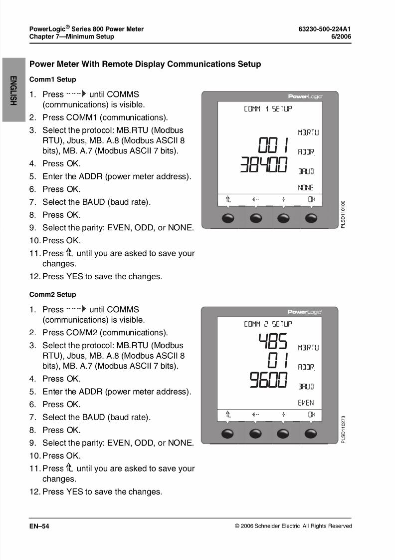
8/2/2019 Medidor Electrico Analizador de Redes Pm800 Shneider
http://slidepdf.com/reader/full/medidor-electrico-analizador-de-redes-pm800-shneider 60/72
© 2006 Schneider Electric All Rights Reserved
PowerLogic ® Series 800 Power Meter 63230-500-224A1Chapter 7—Minimum Setup 6/2006
EN–54
E N G L
I S H
Power Meter With Remote Display Communications Setup
Comm1 Setup
Comm2 Setup
1. Press###:
until COMMS(communications) is visible.
2. Press COMM1 (communications).
3. Select the protocol: MB.RTU (Modbus
RTU), Jbus, MB. A.8 (Modbus ASCII 8
bits), MB. A.7 (Modbus ASCII 7 bits).
4. Press OK.
5. Enter the ADDR (power meter address).
6. Press OK.
7. Select the BAUD (baud rate).
8. Press OK.
9. Select the parity: EVEN, ODD, or NONE.
10.Press OK.
11.Press1; until you are asked to save your
changes.
12. Press YES to save the changes.
#/--3%450
/+
!$$2
A@T$
.N.D
-"245
P L S D 1 1 0 1 0 0
1. Press ###: until COMMS
(communications) is visible.
2. Press COMM2 (communications).
3. Select the protocol: MB.RTU (Modbus
RTU), Jbus, MB. A.8 (Modbus ASCII 8
bits), MB. A.7 (Modbus ASCII 7 bits).
4. Press OK.
5. Enter the ADDR (power meter address).6. Press OK.
7. Select the BAUD (baud rate).
8. Press OK.
9. Select the parity: EVEN, ODD, or NONE.
10.Press OK.
11.Press1; until you are asked to save your
changes.
12. Press YES to save the changes.
#/--3%450
/+
!$$2
A@T$
%6%.
-"245
P L S D 1 1 0 2 7 3

8/2/2019 Medidor Electrico Analizador de Redes Pm800 Shneider
http://slidepdf.com/reader/full/medidor-electrico-analizador-de-redes-pm800-shneider 61/72
© 2006 Schneider Electric All Rights Reserved
63230-500-224A1 PowerLogic ® Series 800 Power Meter6/2006 Chapter 8—Maintenance and Troubleshooting
EN–55
E N
G L I S H
CHAPTER 8—MAINTENANCE AND TROUBLESHOOTING
Introduction
This chapter describes information related to maintenance of your
power meter.
The power meter does not contain any user-serviceable parts. If the
power meter requires service, contact your local sales representative.
Do not open the power meter. Opening the power meter voids the
warranty.
DANGERHAZARD OF ELECTRIC SHOCK, EXPLOSION, OR ARC
FLASH
Do not attempt to service the power meter. CT and PT inputs may
contain hazardous currents and voltages. Only authorized service
personnel from the manufacturer should service the power meter.
Failure to follow this instruction will result in death or serious
injury.
CAUTION
HAZARD OF EQUIPMENT DAMAGE
Do not perform a Dielectric (Hi-Pot) or Megger test on the power
meter. High voltage testing of the power meter may damage the
unit. Before performing Hi-Pot or Megger testing on any equipment
in which the power meter is installed, disconnect all input and
output wires to the power meter.
Failure to follow this instruction can result in equipment
damage.

8/2/2019 Medidor Electrico Analizador de Redes Pm800 Shneider
http://slidepdf.com/reader/full/medidor-electrico-analizador-de-redes-pm800-shneider 62/72
© 2006 Schneider Electric All Rights Reserved
PowerLogic ® Series 800 Power Meter 63230-500-224A1Chapter 8—Maintenance and Troubleshooting 6/2006
EN–56
E N G L
I S H
Power Meter Memory
The power meter uses its nonvolatile memory to retain all data and
metering configuration values. Under the operating temperature
range specified for the power meter, this nonvolatile memory has anexpected life of up to 100 years. The power meter stores its data logs
on a memory chip, which has a life expectancy of up to 20 years
under the operating temperature range specified for the power meter.
The life of the power meter’s internal battery-backed clock is over 10
years at 25°C.
NOTE: Life expectancy is a function of operating conditions; this does
not constitute any expressed or implied warranty.
Identifying the Firmware Version
1. From the first menu level, press ###:
until MAINT is visible.
2. Press MAINT.
3. Press DIAG.
4. Press METER.
The number next to O.S. is the firmware
version. In this example, 10.500 is the
firmware version.
5. After you’re finished, press 1; to return to
the METER SETUP screen.
-%4%2).&/
0-
2%3%4
3.
-/$%,
6
6
P L S D 1 1 0 0 9 4

8/2/2019 Medidor Electrico Analizador de Redes Pm800 Shneider
http://slidepdf.com/reader/full/medidor-electrico-analizador-de-redes-pm800-shneider 63/72
© 2006 Schneider Electric All Rights Reserved
63230-500-224A1 PowerLogic ® Series 800 Power Meter6/2006 Chapter 8—Maintenance and Troubleshooting
EN–57
E N
G L I S H
Viewing the Display in Different Languages
The power meter can be set to use one of three different languages:
English, French, and Spanish. Other languages are available. Please
contact your local sales representative for more information aboutother language options.
The power meter language can be selected by doing the following:
1. From the first menu level, press ###: until
MAINT is visible.
2. Press MAINT.
3. Press SETUP.
4. Enter your password, then press OK.5. Press ###: until LANG is visible.
6. Press LANG.
7. Select the language: ENGL, SPAN, or
FREN.
8. Press OK.
9. Press1;.
10. Press YES to save your changes.
,!.'5!'%
%.',
/+
P L S D 1 1 0 1 0 3

8/2/2019 Medidor Electrico Analizador de Redes Pm800 Shneider
http://slidepdf.com/reader/full/medidor-electrico-analizador-de-redes-pm800-shneider 64/72
© 2006 Schneider Electric All Rights Reserved
PowerLogic ® Series 800 Power Meter 63230-500-224A1Chapter 8—Maintenance and Troubleshooting 6/2006
EN–58
E N G L
I S H
Technical Support
Please refer to the Technical Support Contacts provided in the power
meter shipping carton for a list of support phone numbers by country.
Troubleshooting
The information in Table 8 – 1 describes potential problems and their
possible causes. It also describes checks you can perform or
possible solutions for each. After referring to this table, if you cannot
resolve the problem, contact your local Square D/Schneider Electric
sales representative for assistance.
DANGERHAZARD OF ELECTRIC SHOCK, BURN, OR ARC FLASH
• Apply personal protective equipment (PPE) and follow safe
electrical work practices. See NFPA 70E.
• This equipment must be installed and serviced only by qualified
personnel.
• Turn off all power supplying this equipment before working on or
inside.
• Always use a properly rated voltage sensing device to confirmthat all power is off.
• Qualified persons performing diagnostics or troubleshooting that
require electrical conductors to be energized must comply with
NFPA 70 E - Standard for Electrical Safety Requirements for
Employee Workplaces and OSHA Standards - 29 CFR Part 1910
Subpart S - Electrical.
• Carefully inspect the work area for tools and objects that may
have been left inside the equipment.
• Use caution while removing or installing panels so that they do
not extend into the energized bus; avoid handling the panels,
which could cause personal injury.
Failure to follow this instruction will result in death or
serious injury.

8/2/2019 Medidor Electrico Analizador de Redes Pm800 Shneider
http://slidepdf.com/reader/full/medidor-electrico-analizador-de-redes-pm800-shneider 65/72
© 2006 Schneider Electric All Rights Reserved
63230-500-224A1 PowerLogic ® Series 800 Power Meter6/2006 Chapter 8—Maintenance and Troubleshooting
EN–59
E N
G L I S H
Heartbeat LED
The heartbeat LED helps to troubleshoot the power meter. The LED
works as follows:
• Normal operation — the LED flashes at a steady rate during
normal operation.
• Communications — the LED flash rate changes as the
communications port transmits and receives data. If the LED flash
rate does not change when data is sent from the host computer,
the power meter is not receiving requests from the host computer.
• Hardware — if the heartbeat LED remains lit and does not flash
ON and OFF, there is a hardware problem. Do a hard reset of the
power meter (turn OFF power to the power meter, then restorepower to the power meter). If the heartbeat LED remains lit,
contact your local sales representative.
• Control power and display — if the heartbeat LED flashes, but
the display is blank, the display is not functioning properly. If the
display is blank and the LED is not lit, verify that control power is
connected to the power meter.
Table 8 – 1: Troubleshooting
Potential Problem Possible Cause Possible Solution
The maintenance icon isilluminated on the powermeter display.
When the maintenance icon isilluminated, it indicates a potentialhardware or firmware problem in thepower meter.
When the maintenance icon is illuminated,go to DIAGNOSTICS > MAINTENANCE.Error messages display to indicate thereason the icon is illuminated. Note theseerror messages and call Technical Supportor contact your local sales representativefor assistance.
The display is blank afterapplying control power tothe power meter.
The power meter may not bereceiving the necessary power.
• Verify that the power meter line (L) andneutral (N) terminals (terminals 25 and27) are receiving the necessary power.
• Verify that the heartbeat LED is
blinking.• Check the fuse.

8/2/2019 Medidor Electrico Analizador de Redes Pm800 Shneider
http://slidepdf.com/reader/full/medidor-electrico-analizador-de-redes-pm800-shneider 66/72
© 2006 Schneider Electric All Rights Reserved
PowerLogic ® Series 800 Power Meter 63230-500-224A1Chapter 8—Maintenance and Troubleshooting 6/2006
EN–60
E N G L
I S H
The data being displayed isinaccurate or not what youexpect.
Power meter is grounded incorrectly.Verify that the power meter is grounded asdescribed in “Grounding the Power Meter”
in the installation manual.
Incorrect setup values.
Check that the correct values have beenentered for power meter setup parameters(CT and PT ratings, System Type, NominalFrequency, and so on). See “Set Up thePower Meter” on page EN–51 for setupinstructions.
Incorrect voltage inputs.Check power meter voltage input terminalsL (8, 9, 10, 11) to verify that adequatevoltage is present.
Power meter is wired improperly.
Check that all CTs and PTs are connectedcorrectly (proper polarity is observed) and
that they are energized. Check shortingterminals. See “Wiring Diagrams” onpage EN–28. Initiate a wiring check usingSMS.
Cannot communicate withpower meter from a remotepersonal computer.
Power meter address is incorrect.
Check to see that the power meter iscorrectly addressed. See “Power MeterWith Integrated Display CommunicationsSetup” on page EN–53 for instructions.
Power meter baud rate is incorrect.
Verify that the baud rate of the power metermatches the baud rate of all other deviceson its communications link. See “PowerMeter With Integrated Display
Communications Setup” on page EN–53for instructions.
Communications lines are improperlyconnected.
Verify the power meter communicationsconnections. Refer to theCommunications chapter in theinstallation manual for instructions.
Communications lines are improperlyterminated.
Check to see that a multipointcommunications terminator is properlyinstalled. See “Terminating theCommunications Link” on page EN–38 inthe installation manual for instructions.
Incorrect route statement to powermeter.
Check the route statement. Refer to the
SMS online help for instructions on definingroute statements.
Table 8 – 1: Troubleshooting

8/2/2019 Medidor Electrico Analizador de Redes Pm800 Shneider
http://slidepdf.com/reader/full/medidor-electrico-analizador-de-redes-pm800-shneider 67/72
© 2006 Schneider Electric All Rights Reserved
63230-500-224A1 PowerLogic ® Series 800 Power Meter6/2006 Appendix A—Specifications
EN–61
E N
G L I S H
APPENDIX A—SPECIFICATIONS
Power Meter Specifications
Table A – 1: Specifications
Current Inputs (Each Channel)
Current Range 0 –10 A ac
Nominal Current 5 A ac
Withstand:
Continuous
10 sec/hr
1 sec/hr
15 A
50 A
500 A
Burden < 0.15 VA
Input Impedance < 0.1 Ohm
Voltage Inputs (Each Channel)
Nominal Full Scale 0 – 600 Vac L-L, 347 Vac L-N
Metering Over-range 50%
Input Impedance 5 M Ohm
Metering Frequency Range 45–67 Hz, 350–450 Hz
Metering Category III
Accuracy
Current ±[0.075% Reading + 0.025% full scale]➀
Voltage ±[0.075% Reading + 0.025% full scale]➁
Power ±[0.15% Reading + 0.025% full scale]➂
True Power Factor ±0.002 to 0.500 leading and
±0.002 to 0.500 lagging
Frequency ±0.01 Hz at 45–67 Hz
±0.01 Hz at 350–450 Hz
Energy:
Active
Reactive
IEC 62053-22 and ANSI C12.20 Class 0.5S
IEC 62053-23 Class 2
Specifications based on 50/60 Hz nominal systems.
➀Full scale = 10A. Add 0.006%(°C - 25) to the upper limit error for temperaturesbelow 25°C.
➁Full scale = 600V. Add 0.001%(°C) to the upper limit error for temperaturesabove 50°C.
➂Full scale = 120V x 10A. Add 0.006%(°C) to the upper limit error for temperaturesbelow 25°C.
➃Requires 5°C derating when using the display and control power above 305 Vac.
➄Derate load current 0.56 mA per °C above 25°C.

8/2/2019 Medidor Electrico Analizador de Redes Pm800 Shneider
http://slidepdf.com/reader/full/medidor-electrico-analizador-de-redes-pm800-shneider 68/72
© 2006 Schneider Electric All Rights Reserved
PowerLogic ® Series 800 Power Meter 63230-500-224A1Appendix A—Specifications 6/2006
EN–62
E N G L
I S H
Sampling
Technique Zero blind (takes samples from every cycle)
Samples per cycle 128
Harmonic Resolution
Metered Values 63rd harmonic
Waveform Capture (PM850, PM870)
Capture Initiation Manual or alarm
Cycles Captured PM850: 3 cycles at 128 samples/cycle
PM870: Configurable. From 185 cycles onone channel at 16 samples/cycle to 3 cycleson six channels at 128 samples/cycle. SeeChapter 9—Waveform Capture in thePM800 Reference Manual for moreinformation.
Maximum Captures 5
I/O
Standard KY output
Load Voltage 3–250 ±10% Vdc 6–220 ±10% Vac
Isolation 1350 Vrms isolation
Load Current 100 mA max. at 25°C➄
Maximum Output Frequency 25 HzON Resistance 50 Ohms maximum
Leakage Current 0.03 µA (typical)
Turn ON/OFF Time 3 ms
Standard Digital Input
Turn on voltage 24–125 ±10% Vac/Vdc
Turn off voltage 5 V
Maximum input frequency 25 Hz
Isolation 1350 Vrms
Burden < 5 mA
Table A – 1: Specifications
Specifications based on 50/60 Hz nominal systems.
➀Full scale = 10A. Add 0.006%(°C - 25) to the upper limit error for temperaturesbelow 25°C.
➁Full scale = 600V. Add 0.001%(°C) to the upper limit error for temperaturesabove 50°C.
➂Full scale = 120V x 10A. Add 0.006%(°C) to the upper limit error for temperaturesbelow 25°C.
➃Requires 5°C derating when using the display and control power above 305 Vac.
➄Derate load current 0.56 mA per °C above 25°C.

8/2/2019 Medidor Electrico Analizador de Redes Pm800 Shneider
http://slidepdf.com/reader/full/medidor-electrico-analizador-de-redes-pm800-shneider 69/72
© 2006 Schneider Electric All Rights Reserved
63230-500-224A1 PowerLogic ® Series 800 Power Meter6/2006 Appendix A—Specifications
EN–63
E N
G L I S HControl Power
AC Control Power
Operating Range 115–415 ±10% Vac
Burden 15 VA maximum with options
Frequency 45–67 Hz, 350–450 Hz
Ride Through 45 ms at 120 Vac
DC Control Power
Operating Range 125–250 ±20% Vdc
Burden 10 W maximum with options
Ride Through 45 ms at 125 Vdc
Environment
Operating Temperature
Meter -25°C to +70°C➃
Display -10°C to +50°C
Operating Environment
Relative Humidity 5–95% (non-condensing)
Maximum Elevation 3,000 m
Pollution Degree 2
IP Rating
Meter 30Display
NOTE: The display must be mounted on a flat surface.
52
Regulatory/Standards Compliance
Emissions
Radiated FCC part 15 Class A, EN55011
Conducted FCC part 15 Class A, EN55011
Harmonics IEC 61000-3-2
Flicker IEC 61000-3-3
Table A – 1: Specifications
Specifications based on 50/60 Hz nominal systems.
➀Full scale = 10A. Add 0.006%(°C - 25) to the upper limit error for temperaturesbelow 25°C.
➁Full scale = 600V. Add 0.001%(°C) to the upper limit error for temperaturesabove 50°C.
➂Full scale = 120V x 10A. Add 0.006%(°C) to the upper limit error for temperaturesbelow 25°C.
➃Requires 5°C derating when using the display and control power above 305 Vac.
➄Derate load current 0.56 mA per °C above 25°C.

8/2/2019 Medidor Electrico Analizador de Redes Pm800 Shneider
http://slidepdf.com/reader/full/medidor-electrico-analizador-de-redes-pm800-shneider 70/72
© 2006 Schneider Electric All Rights Reserved
PowerLogic ® Series 800 Power Meter 63230-500-224A1Appendix A—Specifications 6/2006
EN–64
E N G L
I S H
Immunity IEC 61000-6
ESD IEC 61000-4-2 Level 3
Radiated IEC 61000-4-3 Level 3
EFT IEC 61000-4-4 Level 3
Surges IEC 61000-4-5 Level 3
Conducted IEC 61000-4-6 Level 3
Magnetic Field IEC 61000-4-8 Level 3
Voltage Dips IEC 61000-4-11 Level
Standards (listed)
USA UL 61010 / IEC 61010
Europe CE per EN 61010
Table A – 1: Specifications
Specifications based on 50/60 Hz nominal systems.
➀Full scale = 10A. Add 0.006%(°C - 25) to the upper limit error for temperaturesbelow 25°C.
➁Full scale = 600V. Add 0.001%(°C) to the upper limit error for temperaturesabove 50°C.
➂Full scale = 120V x 10A. Add 0.006%(°C) to the upper limit error for temperaturesbelow 25°C.
➃Requires 5°C derating when using the display and control power above 305 Vac.
➄Derate load current 0.56 mA per °C above 25°C.

8/2/2019 Medidor Electrico Analizador de Redes Pm800 Shneider
http://slidepdf.com/reader/full/medidor-electrico-analizador-de-redes-pm800-shneider 71/72
63230-500-224A1 PowerLogic ® Series 800 Power Meter6/2006 Index
© 2006 Schneider Electric All Rights Reserved EN–65
E N G
L I S H
INDEX
Aaddress
device address EN–60
Bbaud rate EN–60
onboard EN–35
remote display EN–42
box contents EN–7
Cchanging values EN–48CM2000
connecting to EN–39communications
daisy-chaining devices EN–
36
first device on daisy chain
EN–38
Modbus or Jbus EN–37
onboard
baud rate EN–35
distances EN–35
parity EN–35
port EN–35
protocols EN–35
problems with PC
communication EN–60
remote display
baud rate EN–42
distances EN–42
parity EN–42
port EN–42
protocols EN–42
setup EN–53, EN–54terminating EN–38
connectionswiring EN–25
contacting technical supportEN–58converter
4- to 2-wire EN–39
CTsetup EN–51
Ddaisy-chain
2-wire devices EN–37
2-wire Modbus or Jbus EN–
374-wire devices EN–37
to a CM2000 EN–39
data logstorage in power meter EN–
56
devicedaisy-chaining
communications EN–36
dimensionspower meter EN–15–EN–16
remote display EN–21
displaybutton operation EN–47
changing values EN–48
menu EN–48
operation EN–47
EEthernet Gateway
connections EN–41
Ffeatures EN–8firmware EN–9
identifying the version EN–
56
fuse recommendations EN–32
Ggetting technical support EN–58
Hheartbeat LED EN–59
Hi-Pot testing EN–55Iinstallation
considerations EN–13
Llanguage
changing EN–57
setup EN–57
LEDheartbeat EN–59
Mmaintenancemaintenance icon EN–59
of power meter EN–55
megger testing EN–55memory
power meter memory EN–56
menu EN–48mounting
dimensions EN–15–EN–16
on DIN rail EN–20
replacing analog meters
EN–18
with integrated display EN–
17
with remote display EN–23–
EN–24
without display EN–20
Nnetwork connections
using Ethernet
Communications Card EN–
41
using Ethernet Gateway
EN–41
nonvolatile memory EN–56Oonboard communications
baud rate EN–35
distances EN–35
parity EN–35
port EN–35
protocols EN–35
operationdisplay EN–47
problems with the power
meter EN–59
Pparity
onboard EN–35
remote display EN–42
portonboard EN–35
power meteraccessories EN–6
dimensions EN–15–EN–16
firmware EN–9hardware EN–3
8/2/2019 Medidor Electrico Analizador de Redes Pm800 Shneider
http://slidepdf.com/reader/full/medidor-electrico-analizador-de-redes-pm800-shneider 72/72
PowerLogic ® Series 800 Power Meter 63230-500-224A1Index 6/2006
E NG
L I S H
models EN–6, EN–13
remote display
dimensions EN–21
mounting EN–23–EN–24
setup EN–51
with display
parts EN–5
without display
mounting EN–20
parts EN–4
problemssee troubleshooting EN–58
protocolremote display EN–42
Rremote display
communications
baud rate EN–42
distances EN–42
parity EN–42
port EN–42
protocol EN–42
connections EN–43
mounting EN–23–EN–24
RS485, 2-wire connections
EN–44
RS485, 4-wire connections
EN–44, EN–45
route statement EN–60RS485
onboard
2-wire EN–35
remote display
2-wire EN–42, EN–44
4-wire EN–42, EN–44,
EN–45Ssetup
communications EN–53,
EN–54
setup EN–52, EN–53
system types EN–26
Ttechnical support EN–58termination
last device EN–38
testingdielectric (hi-pot) test EN–55
megger test EN–55
Wwiring
fuse recommendations EN–
32
Modbus or Jbus EN–37
troubleshooting EN–60