Embed Size (px)
Citation preview

www.iap.uni-jena.de
Medical Photonics Lecture 1.2Optical Engineering
Lecture 9: Instruments II
2017-12-21
Michael Kempe
Winter term 2017

2
Contents
No Subject Ref Detailed Content
1 Introduction Gross Materials, dispersion, ray picture, geometrical approach, paraxial approximation
2 Geometrical optics Gross Ray tracing, matrix approach, aberrations, imaging, Lagrange invariant
3 Diffraction Gross Basic phenomena, wave optics, interference, diffraction calculation, point spread function, transfer function
4 Components Kempe Lenses, micro-optics, mirrors, prisms, gratings, fibers
5 Optical systems Gross Field, aperture, pupil, magnification, infinity cases, lens makers formula, etendue, vignetting
6 Aberrations Gross Introduction, primary aberrations, miscellaneous7 Image quality Gross Spot, ray aberration curves, PSF and MTF, criteria
8 Instruments I Kempe Human eye, loupe, eyepieces, photographic lenses, zoom lenses, telescopes
9 Instruments II Kempe Microscopic systems, micro objectives, illumination, scanning microscopes, contrasts
10 Instruments III Kempe Medical optical systems, endoscopes, ophthalmic devices, surgical microscopes
11 Optic design Gross Aberration correction, system layouts, optimization, realization aspects
12 Photometry Gross Notations, fundamental laws, Lambert source, radiative transfer, photometry of optical systems, color theory
13 Illumination systems Gross Light sources, basic systems, quality criteria, nonsequential raytrace14 Metrology Gross Measurement of basic parameters, quality measurements
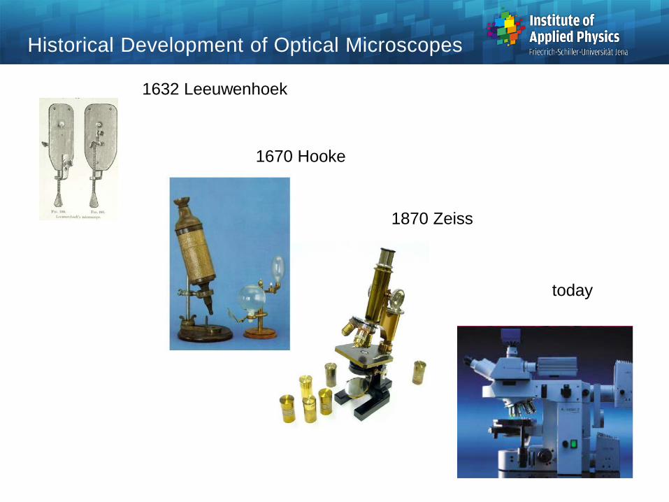
Historical Development of Optical Microscopes
1670 Hooke
1632 Leeuwenhoek
1870 Zeiss
today
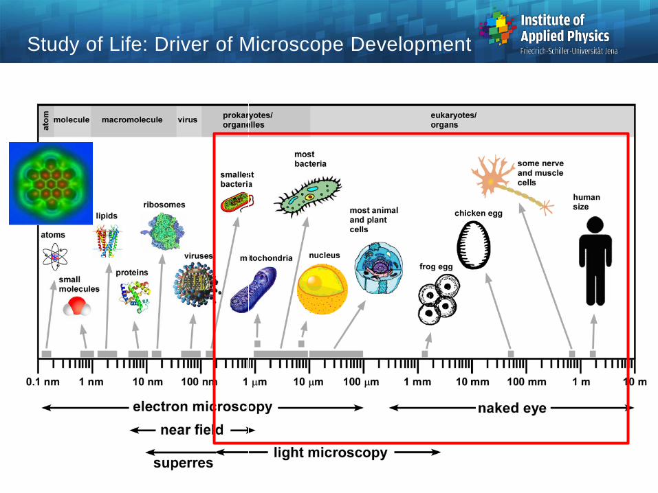
Study of Life: Driver of Microscope Development
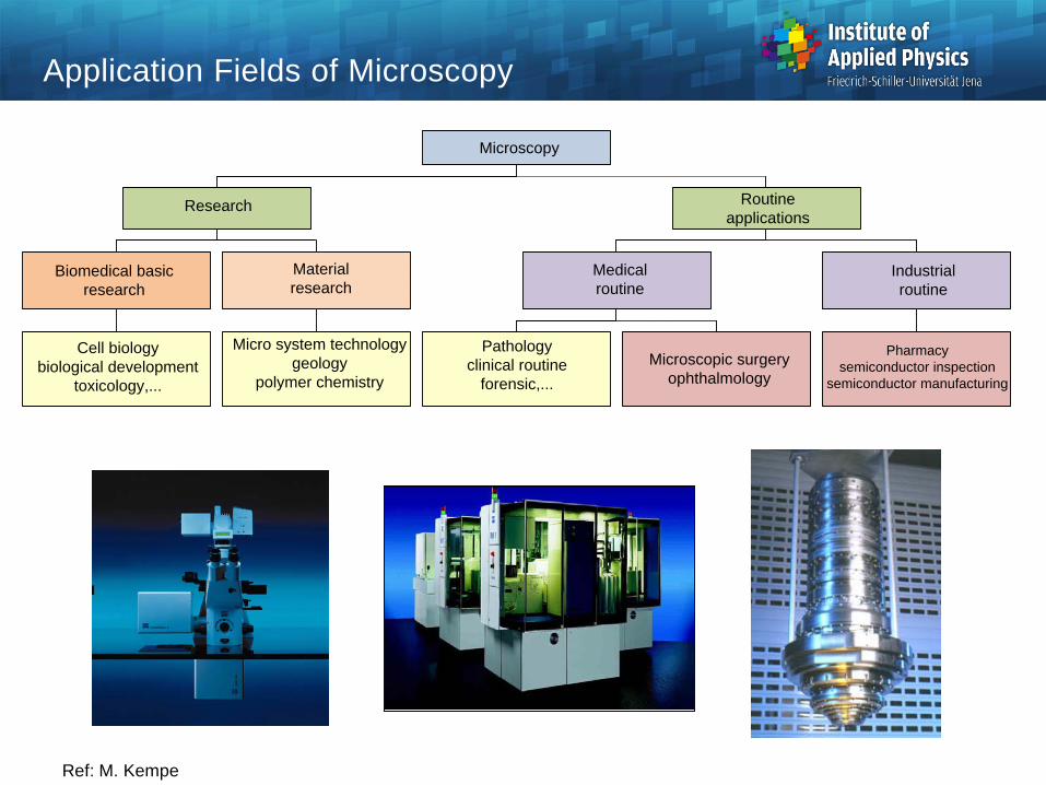
Application Fields of Microscopy
Ref: M. Kempe
Cell biologybiological development
toxicology,...
Biomedical basic research
Materialresearch
Research
Medicalroutine
Pharmacysemiconductor inspection
semiconductor manufacturing
Industrialroutine
Routine applications
Microscopy
Micro system technologygeology
polymer chemistry
Pathologyclinical routine
forensic,...Microscopic surgery
ophthalmology
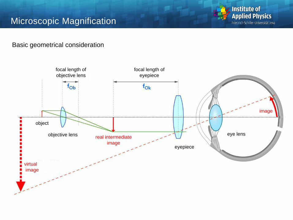
Microscopic Magnification
Basic geometrical consideration
objective lens
object
focal length of objective lens
focal length of eyepiece
eye lens
eyepiece
real intermediate image
image
virtual image

Image Planes and Pupils
Principal setup of a classical compound optical microscope upper row : image planes, lower row : pupil planes
Köhler illumination
source
collector condenser objective eyepiece eyetube lens
eyepupil
exit pupilobjective
aperture stop
field stop
object intermediate image image
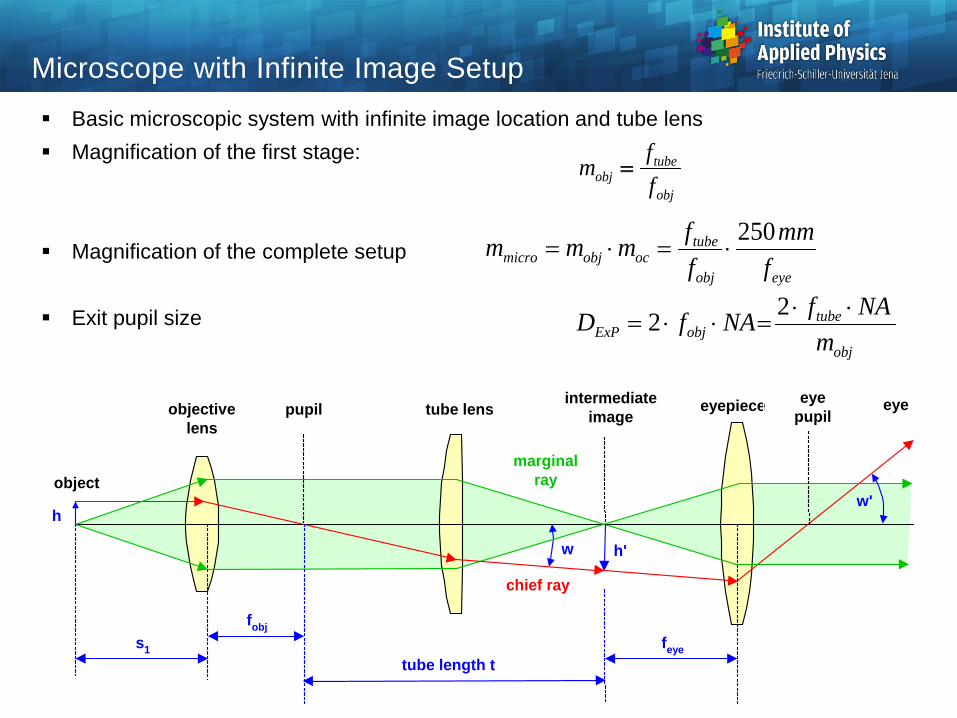
Microscope with Infinite Image Setup Basic microscopic system with infinite image location and tube lens Magnification of the first stage:
Magnification of the complete setup
Exit pupil size
eyeobj
tubeocobjmicro f
mmffmmm 250
⋅=⋅=
obj
tubeobj f
fm =
obj
tubeobjExP m
NAfNAfD ⋅⋅=⋅⋅=
22
marginalray
eyepiece
chief ray
w'
intermediateimageobjective
lens
object
eye
tube length t
h'
h
fobj
w
pupil tube lens
s1 feye
eyepupil
Microscope Resolution
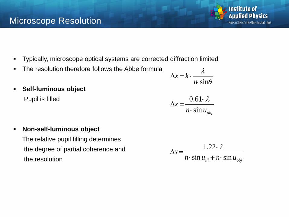
Typically, microscope optical systems are corrected diffraction limited The resolution therefore follows the Abbe formula
Self-luminous objectPupil is filled
Non-self-luminous objectThe relative pupil filling determinesthe degree of partial coherence and the resolution
objunx
sin61.0
⋅⋅
=λ
∆
objill ununx
sinsin22.1
⋅+⋅⋅
=λ
∆
θλsin⋅
⋅=∆n
kx
Resolution and Magnification
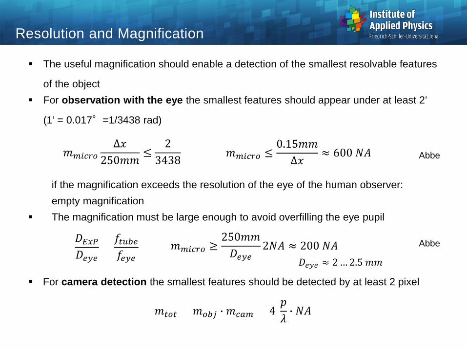
The useful magnification should enable a detection of the smallest resolvable features
of the object For observation with the eye the smallest features should appear under at least 2’
(1’ = 0.017°=1/3438 rad)
if the magnification exceeds the resolution of the eye of the human observer:empty magnification
The magnification must be large enough to avoid overfilling the eye pupil
For camera detection the smallest features should be detected by at least 2 pixel
𝑚𝑚𝑚𝑚𝑚𝑚𝑚𝑚𝑚𝑚𝑚𝑚∆𝑥𝑥
250𝑚𝑚𝑚𝑚≤
23438
𝑚𝑚𝑡𝑡𝑚𝑚𝑡𝑡 = 𝑚𝑚𝑚𝑚𝑜𝑜𝑜𝑜 � 𝑚𝑚𝑚𝑚𝑐𝑐𝑚𝑚 > 4𝑝𝑝𝜆𝜆 � 𝑁𝑁𝑁𝑁
𝑚𝑚𝑚𝑚𝑚𝑚𝑚𝑚𝑚𝑚𝑚𝑚 ≤0.15𝑚𝑚𝑚𝑚∆𝑥𝑥
≈ 600 𝑁𝑁𝑁𝑁
𝐷𝐷𝐸𝐸𝐸𝐸𝐸𝐸𝐷𝐷𝑒𝑒𝑒𝑒𝑒𝑒
=𝑓𝑓𝑡𝑡𝑡𝑡𝑜𝑜𝑒𝑒𝑓𝑓𝑒𝑒𝑒𝑒𝑒𝑒
𝑚𝑚𝑚𝑚𝑚𝑚𝑚𝑚𝑚𝑚𝑚𝑚 ≥250𝑚𝑚𝑚𝑚𝐷𝐷𝑒𝑒𝑒𝑒𝑒𝑒
2𝑁𝑁𝑁𝑁 ≈ 200 𝑁𝑁𝑁𝑁𝐷𝐷𝑒𝑒𝑒𝑒𝑒𝑒 ≈ 2 … 2.5 𝑚𝑚𝑚𝑚
Abbe
Abbe
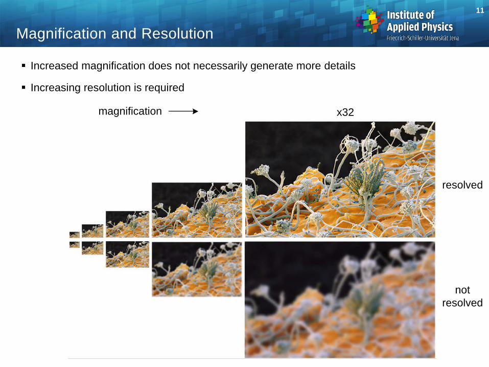
Increased magnification does not necessarily generate more details
Increasing resolution is required
11
Magnification and Resolution
x2x4
x8
x16
x32
resolved
magnification
not resolved
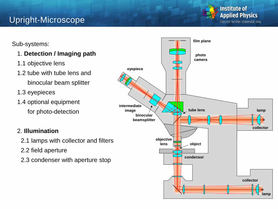
Upright-Microscope
Sub-systems:1. Detection / Imaging path1.1 objective lens1.2 tube with tube lens and
binocular beam splitter1.3 eyepieces1.4 optional equipment
for photo-detection
2. Illumination2.1 lamps with collector and filters2.2 field aperture2.3 condenser with aperture stop
eyepiece
photocamera
tube lens
objectivelens
lamp
lamp
collector
collector
condensor
intermediateimage
binocularbeamsplitter
object
film plane
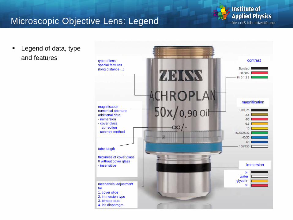
Microscopic Objective Lens: Legend
Legend of data, typeand features
immersion
contrast
magnification
oilwater
glycerinall
magnificationnumerical apertureadditional data:- immersion- cover glass correction- contrast method
mechanical adjustment for1. cover slide2. immersion type3. temperature4. iris diaphragm
tube length
thickness of cover glass0 without cover glass- insensitive
type of lensspecial features(long distance,...)
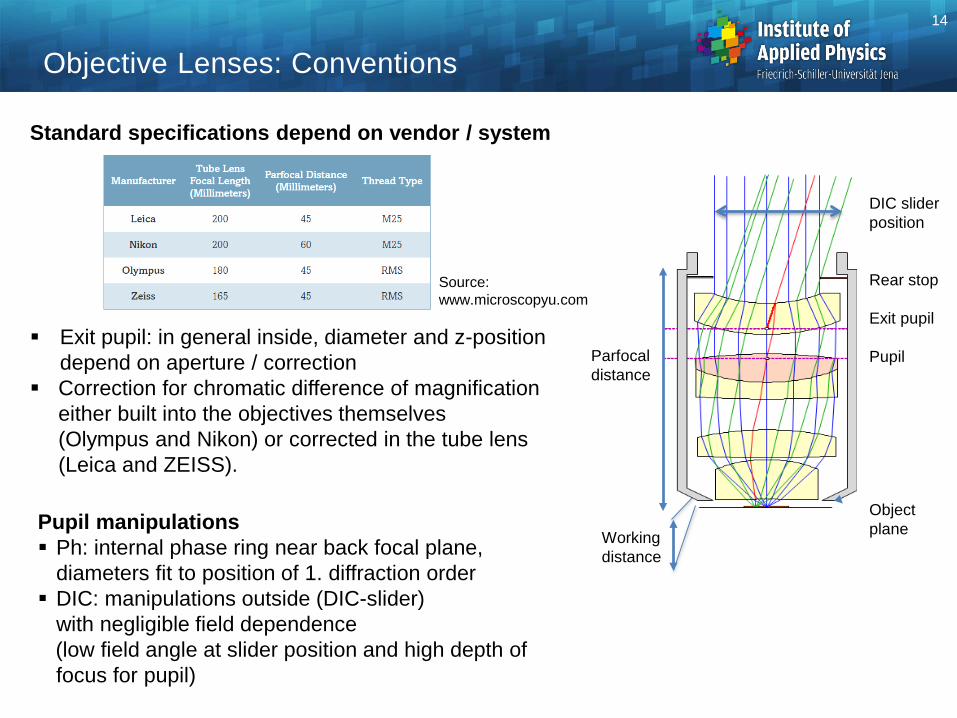
Standard specifications depend on vendor / system
Exit pupil: in general inside, diameter and z-position depend on aperture / correction
Correction for chromatic difference of magnification either built into the objectives themselves (Olympus and Nikon) or corrected in the tube lens (Leica and ZEISS).
DIC slider position
Rear stop
Exit pupil
Pupil
Object plane Pupil manipulations
Ph: internal phase ring near back focal plane, diameters fit to position of 1. diffraction order DIC: manipulations outside (DIC-slider)
with negligible field dependence(low field angle at slider position and high depth of focus for pupil)
Objective Lenses: Conventions14
Parfocaldistance
Working distance
Source:www.microscopyu.com
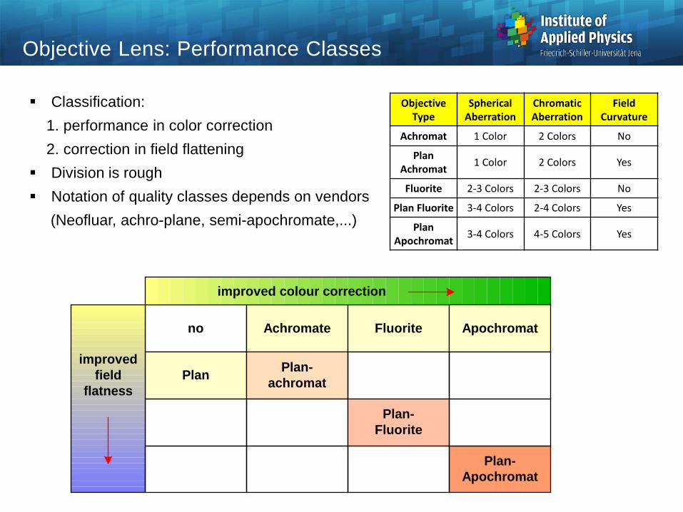
Objective Lens: Performance Classes
Classification:1. performance in color correction2. correction in field flattening
Division is rough Notation of quality classes depends on vendors
(Neofluar, achro-plane, semi-apochromate,...)
improvedfield
flatness
improved colour correction
Achromate
Plan-Apochromat
Fluorite Apochromatno
Plan Plan-achromat
Plan-Fluorite
ObjectiveType
SphericalAberration
ChromaticAberration
FieldCurvature
Achromat 1 Color 2 Colors No
Plan Achromat 1 Color 2 Colors Yes
Fluorite 2-3 Colors 2-3 Colors No
Plan Fluorite 3-4 Colors 2-4 Colors Yes
Plan Apochromat 3-4 Colors 4-5 Colors Yes
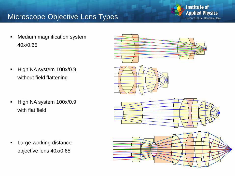
Microscope Objective Lens Types
Medium magnification system40x/0.65
High NA system 100x/0.9without field flattening
High NA system 100x/0.9with flat field
Large-working distanceobjective lens 40x/0.65

Microscope Objective Lens: High NA 100x/0.93
Point spread function Diffraction limit: 80% Strehl ratio Typical: performance in the blue critical
644 nm
0 1.5 µm0 1.5 µm 0 1.5 µm
546 nm480 nm
-1.5 µm
diffractionlimit
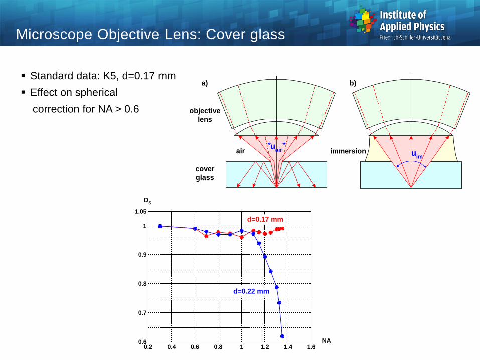
Microscope Objective Lens: Cover glass
Standard data: K5, d=0.17 mm Effect on spherical
correction for NA > 0.6
air uimimmersion
coverglass
objectivelens
uair
a) b)
0.2 0.4 0.6 0.8 1 1.2 1.4 1.60.6
0.7
0.8
0.9
1
1.05
DS
NA
d=0.22 mm
d=0.17 mm
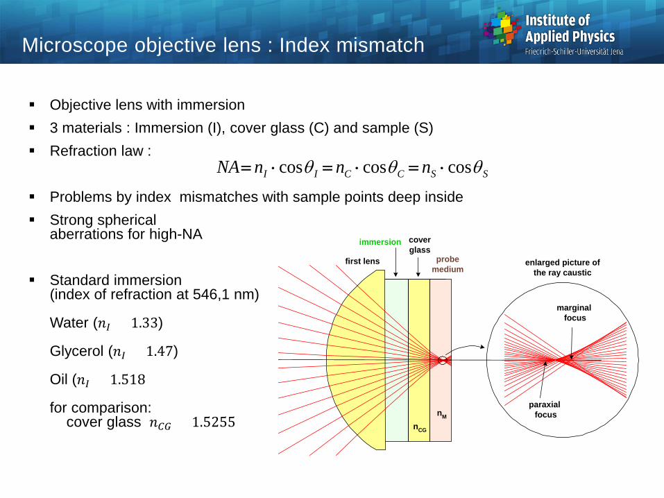
Microscope objective lens : Index mismatch
Objective lens with immersion 3 materials : Immersion (I), cover glass (C) and sample (S) Refraction law :
Problems by index mismatches with sample points deep inside Strong spherical
aberrations for high-NA
Standard immersion(index of refraction at 546,1 nm)
Water (𝑛𝑛𝐼𝐼 = 1.33)
Glycerol (𝑛𝑛𝐼𝐼 = 1.47)
Oil (𝑛𝑛𝐼𝐼 = 1.518)
for comparison: cover glass 𝑛𝑛𝐶𝐶𝐶𝐶 = 1.5255
first lens
immersion coverglass
probemedium
enlarged picture ofthe ray caustic
paraxial focus
marginal focus
nCG
nM
SSCCII nnnNA θθθ coscoscos ⋅=⋅=⋅=

Tube Optical System: Tube Lens
Simple tube lens Magnification
On axis : diffraction limited Dominant residual aberration:
lateral color (corrected together with objective lens)
objectiveexit pupil
d = 100 mmf'TL = 164 mm
tubelens
yTL
DFV = 25 mm
intermediateimage
DExP
480 nm
0
8.8 mm
12.5 mm
546 nm 644 nm
obj
tubeobj f
fm =
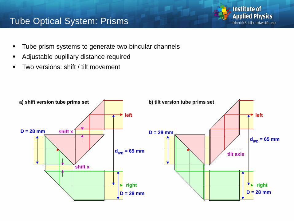
Tube Optical System: Prisms
Tube prism systems to generate two bincular channels Adjustable pupillary distance required Two versions: shift / tilt movement
a) shift version tube prims set
left
right
dIPD = 65 mm
D = 28 mm
D = 28 mm
left
right
dIPD = 65 mmD = 28 mm
D = 28 mm
shift x
b) tilt version tube prims set
shift x
tilt axis
22
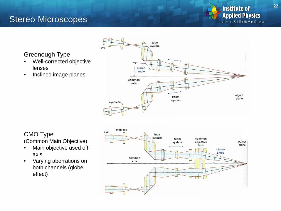
Stereo Microscopes
Greenough Type• Well-corrected objective
lenses• Inclined image planes
CMO Type (Common Main Objective)• Main objective used off-
axis • Varying aberrations on
both channels (globe effect)
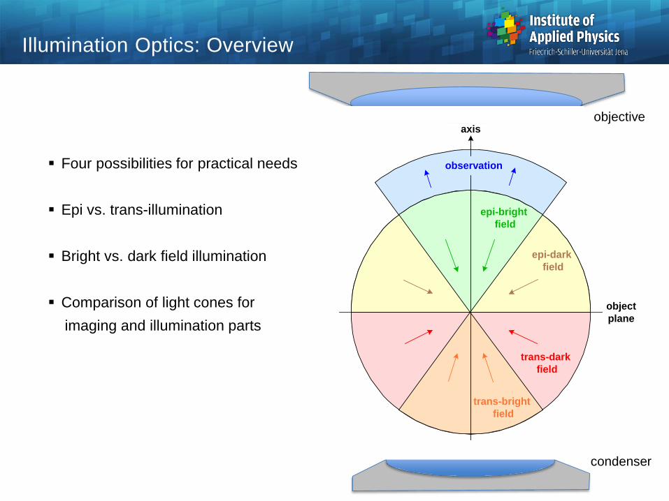
Illumination Optics: Overview
Four possibilities for practical needs
Epi vs. trans-illumination
Bright vs. dark field illumination
Comparison of light cones forimaging and illumination parts
axis
observation
epi-dark field
trans-bright field
trans-dark field
epi-bright field
objectplane
objective
condenser

Illumination Optics: Overview
Instrumental realizations
a) incident illuminationbright field
b) incident illuminationdark field
c) transmitted illuminationbright field
d) transmitted illuminationdark field
ringmirror
observation
illumination
objectplane
ringmirror
objectivelens
objectplane
observation
illumination
observation
ringcondenser
objectplane
illumination
condenser
objectplane
observation
illumination
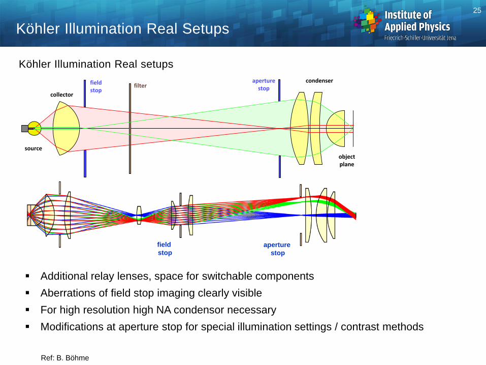
Köhler Illumination Real Setups
Additional relay lenses, space for switchable components Aberrations of field stop imaging clearly visible For high resolution high NA condensor necessary Modifications at aperture stop for special illumination settings / contrast methods
Köhler Illumination Real setups
aperture stop
field stop
condenser
objectplane
aperturestop
field stop
filtercollector
source
25
Ref: B. Böhme

Contrasts in Microscopy
• Biomedical specimen exhibit weak natural contrast in transilluminationor brightfield imaging
Source: zeiss-campus.magnet.fsu.edu
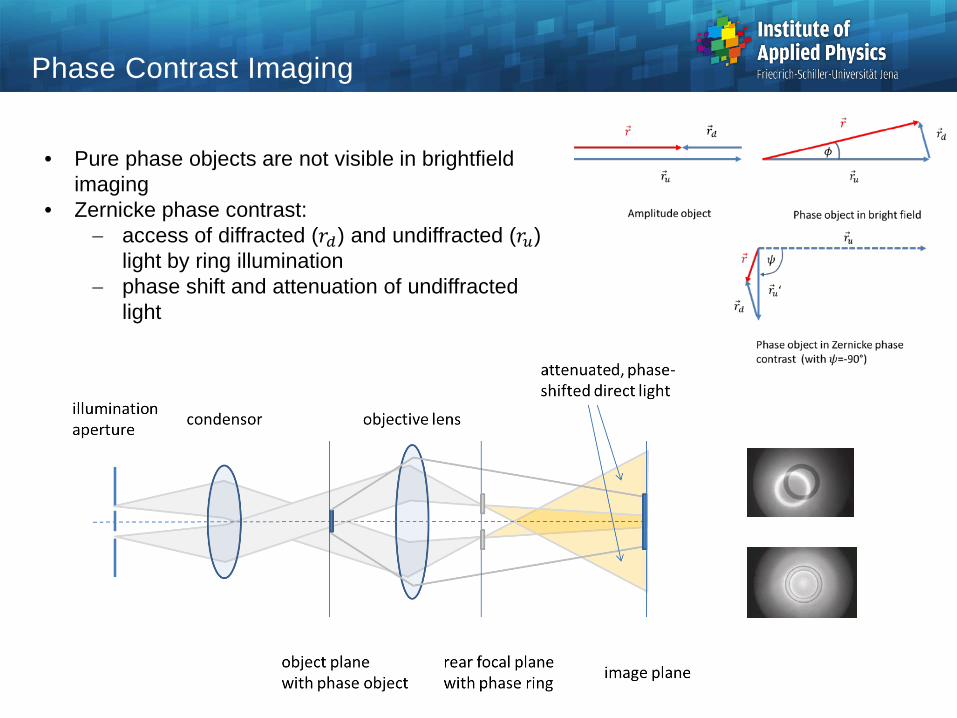
Phase Contrast Imaging
• Pure phase objects are not visible in brightfieldimaging
• Zernicke phase contrast: − access of diffracted (𝑟𝑟𝑑𝑑) and undiffracted (𝑟𝑟𝑡𝑡)
light by ring illumination − phase shift and attenuation of undiffracted
light
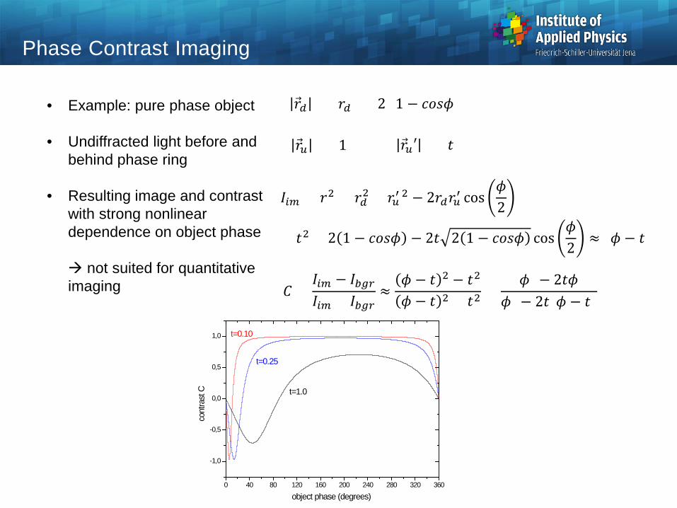
Phase Contrast Imaging
𝐼𝐼𝑚𝑚𝑚𝑚 = 𝑟𝑟2 = 𝑟𝑟𝑑𝑑2 + 𝑟𝑟𝑡𝑡′ 2 − 2𝑟𝑟𝑑𝑑𝑟𝑟𝑡𝑡′ cos𝜙𝜙2
= 𝑡𝑡2 + 2 1 − 𝑐𝑐𝑐𝑐𝑐𝑐𝜙𝜙 − 2𝑡𝑡 2 1 − 𝑐𝑐𝑐𝑐𝑐𝑐𝜙𝜙 cos𝜙𝜙2
≈ (𝜙𝜙 − 𝑡𝑡)²
)𝑟𝑟𝑑𝑑 ² = 𝑟𝑟𝑑𝑑² = 2 (1 − 𝑐𝑐𝑐𝑐𝑐𝑐𝜙𝜙
𝑟𝑟𝑡𝑡 ² = 1 𝑟𝑟𝑡𝑡′ ² = 𝑡𝑡²
• Example: pure phase object
• Undiffracted light before and behind phase ring
• Resulting image and contrast with strong nonlinear dependence on object phase
not suited for quantitative imaging 𝐶𝐶 =
𝐼𝐼𝑚𝑚𝑚𝑚 − 𝐼𝐼𝑜𝑜𝑏𝑏𝑚𝑚𝐼𝐼𝑚𝑚𝑚𝑚 + 𝐼𝐼𝑜𝑜𝑏𝑏𝑚𝑚
≈𝜙𝜙 − 𝑡𝑡 2 − 𝑡𝑡2
𝜙𝜙 − 𝑡𝑡 2 + 𝑡𝑡2=
𝜙𝜙² − 2𝑡𝑡𝜙𝜙)𝜙𝜙² − 2𝑡𝑡(𝜙𝜙 − 𝑡𝑡
0 40 80 120 160 200 240 280 320 360
-1,0
-0,5
0,0
0,5
1,0
cont
rast
C
object phase (degrees)
t=0.10
t=0.25
t=1.0
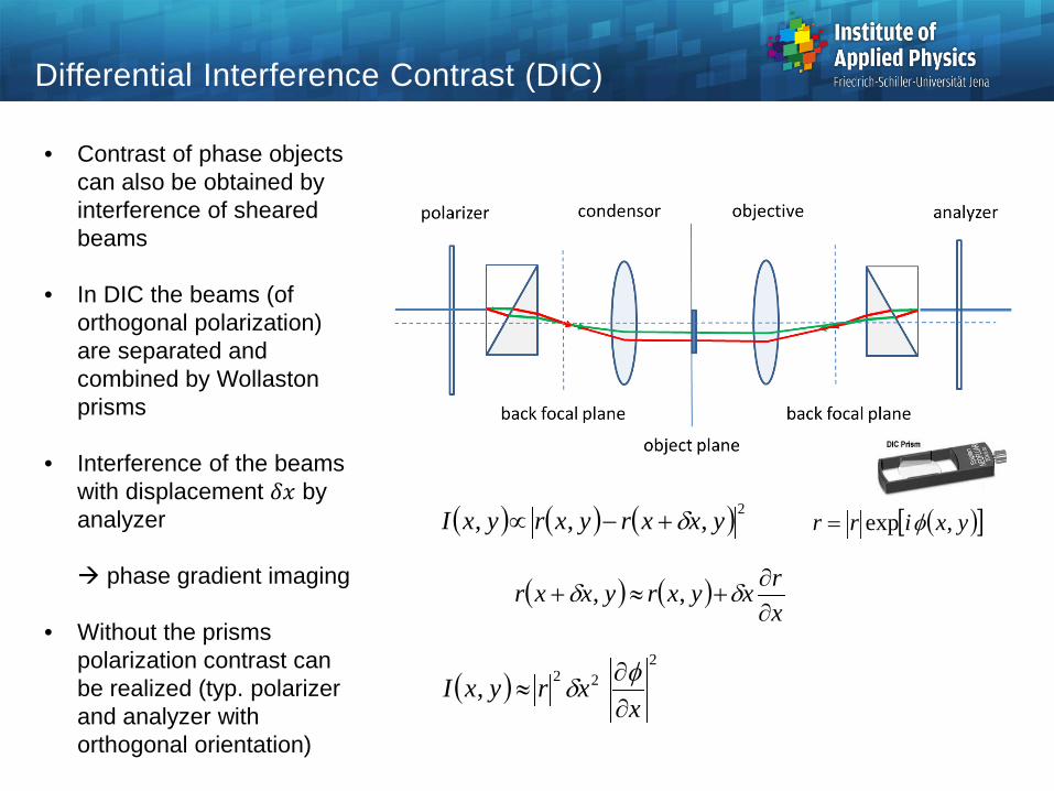
Differential Interference Contrast (DIC)
• Contrast of phase objects can also be obtained by interference of sheared beams
• In DIC the beams (of orthogonal polarization) are separated and combined by Wollaston prisms
• Interference of the beams with displacement 𝛿𝛿𝑥𝑥 by analyzer
phase gradient imaging
• Without the prisms polarization contrast can be realized (typ. polarizer and analyzer with orthogonal orientation)
( ) ( ) ( )2,,, yxxryxryxI δ+−∝ ( )[ ]yxirr ,exp φ=
( ) ( )xrxyxryxxr∂∂
+≈+ δδ ,,
( )2
22,x
xryxI∂∂
≈φδ
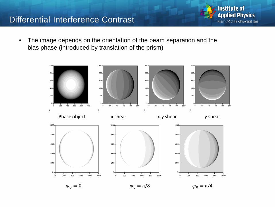
Differential Interference Contrast
• The image depends on the orientation of the beam separation and thebias phase (introduced by translation of the prism)
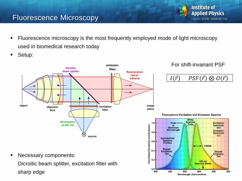
Fluorescence Microscopy
Fluorescence microscopy is the most frequently employed mode of light microscopy used in biomedical research today
Setup:
Necessary components:Dicroitic beam splitter, excitation filter withsharp edge
UVsource
object objectivelens
imageplane
illuminationat 365 nm
fluorescencered or
infrared
dicroiticbeam splitter
excitationfilter
UV blocfilter
emission filter
𝐼𝐼 𝑟𝑟 = 𝑃𝑃𝑃𝑃𝑃𝑃 𝑟𝑟 ⊗ 𝑂𝑂 𝑟𝑟
For shift-invariant PSF
Source: zeiss-campus.magnet.fsu.edu
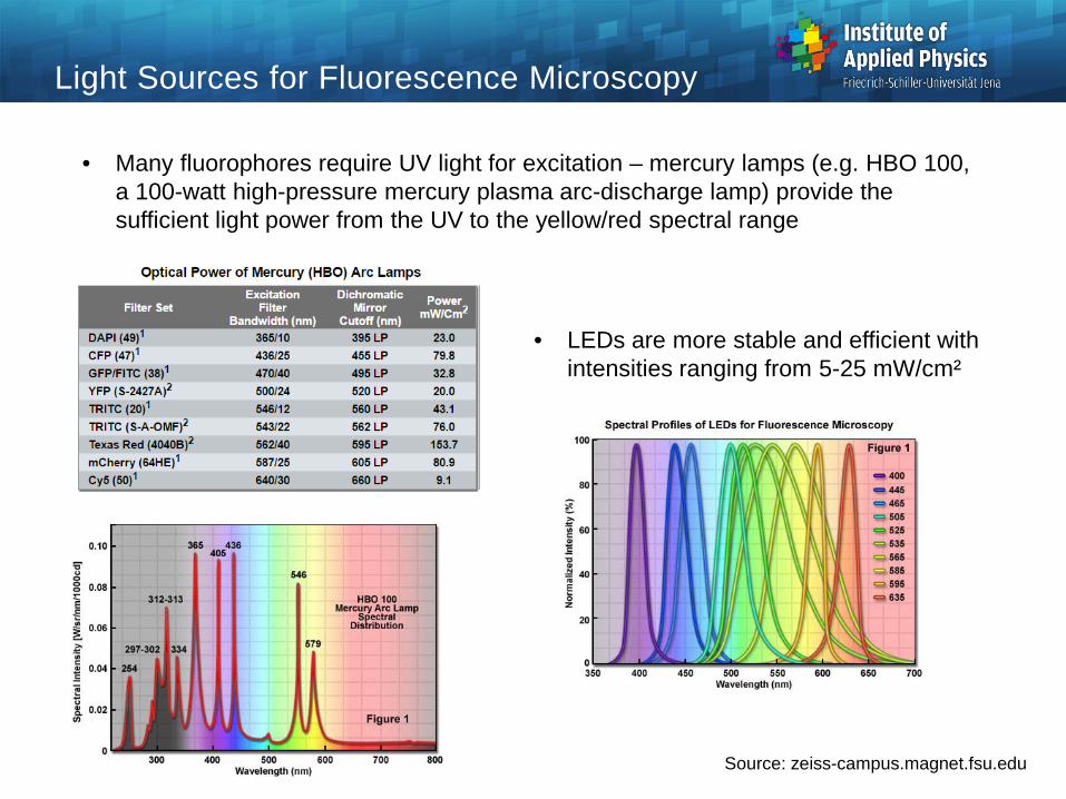
Light Sources for Fluorescence Microscopy
• Many fluorophores require UV light for excitation – mercury lamps (e.g. HBO 100, a 100-watt high-pressure mercury plasma arc-discharge lamp) provide the sufficient light power from the UV to the yellow/red spectral range
• LEDs are more stable and efficient with intensities ranging from 5-25 mW/cm²
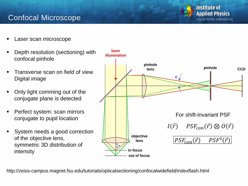
Laser scan microscope
Depth resolution (sectioning) withconfocal pinhole
Transverse scan on field of viewDigital image
Only light comming out of theconjugate plane is detected
Perfect system: scan mirrorsconjugate to pupil location
System needs a good correctionof the objective lens,symmetric 3D distribution ofintensity
http://zeiss-campus.magnet.fsu.edu/tutorials/opticalsectioning/confocalwidefield/indexflash.html
Confocal Microscope
θ'
objectivelens
pinhole lens pinhole CCD
θin focusout of focus
laserillumination
𝐼𝐼 𝑟𝑟 = 𝑃𝑃𝑃𝑃𝑃𝑃𝑚𝑚𝑚𝑚𝑐𝑐 𝑟𝑟 ⊗ 𝑂𝑂 𝑟𝑟
For shift-invariant PSF
𝑃𝑃𝑃𝑃𝑃𝑃𝑚𝑚𝑚𝑚𝑐𝑐 𝑟𝑟 = 𝑃𝑃𝑃𝑃𝑃𝑃𝑃 𝑟𝑟
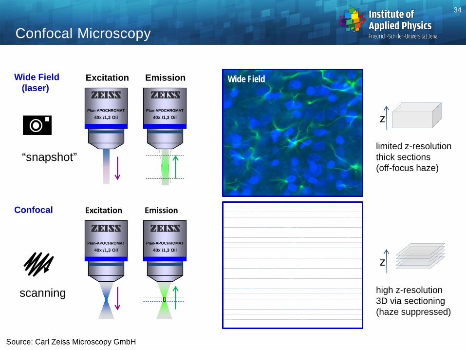
Confocal Microscopy
34
Confocal
Wide FieldWide Field(laser)
Confocal
high z-resolution3D via sectioning(haze suppressed)
limited z-resolutionthick sections(off-focus haze)
“snapshot”
scanning
z
z
Excitation
Plan-APOCHROMAT
40x /1,3 Oil
Emission
Plan-APOCHROMAT
40x /1,3 Oil
Excitation
Plan-APOCHROMAT
40x /1,3 Oil
Emission
Plan-APOCHROMAT
40x /1,3 Oil
Source: Carl Zeiss Microscopy GmbH
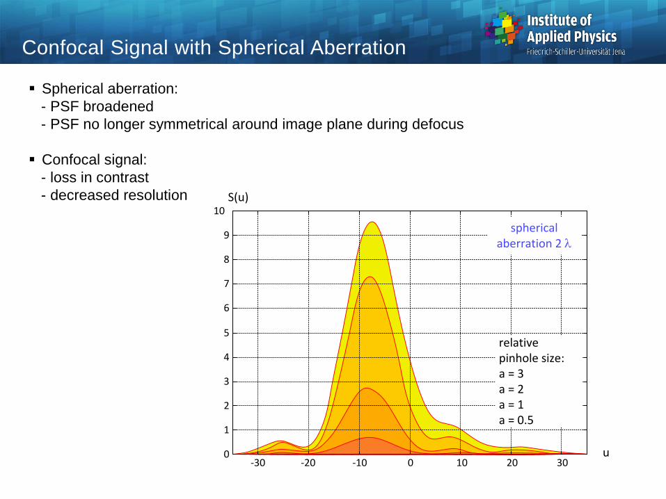
Confocal Signal with Spherical Aberration
S(u)
u-30 -20 -10 0 10 20 30
0
1
2
3
4
5
6
7
8
9
10
relative pinhole size:a = 3a = 2a = 1a = 0.5
spherical aberration 2 λ
Spherical aberration:- PSF broadened- PSF no longer symmetrical around image plane during defocus
Confocal signal:- loss in contrast- decreased resolution

Multispectral Detection
• Simultaneous imaging of many colors by spectrally resolved detection enables the imaging of multi-label samples
• Particularly relevant for fluorophores with overlapping spectra (e.g. fluorescent proteins)
Source: Carl Zeiss Microscopy GmbH
grating
32-Channel PMT
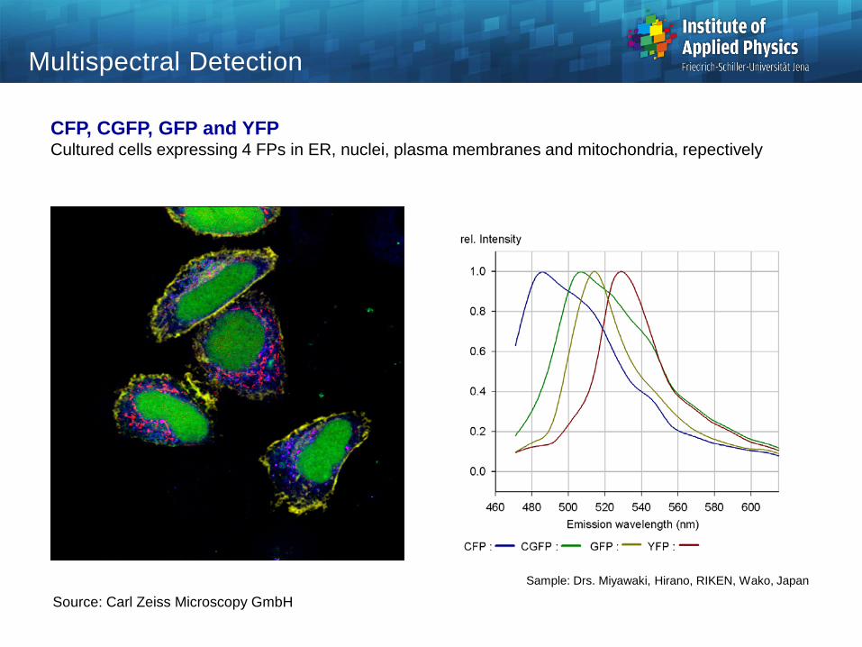
Multispectral Detection
CFP, CGFP, GFP and YFPCultured cells expressing 4 FPs in ER, nuclei, plasma membranes and mitochondria, repectively
Sample: Drs. Miyawaki, Hirano, RIKEN, Wako, Japan
CFP CGFP
GFP YFP
Source: Carl Zeiss Microscopy GmbH
CFP CGFP
GFP YFP
Nice Holidays and a Happy New Year!