Embed Size (px)
Citation preview
8/8/2019 Medical Dosimetry p124
http://slidepdf.com/reader/full/medical-dosimetry-p124 1/11
doi:10.1016/j.meddos.2008.02.005
USE OF THE BRAINLAB EXACTRAC X-RAY 6D SYSTEM IN
IMAGE-GUIDED RADIOTHERAPY
JIAN-YUE JIN, PH.D., FANG-FANG YIN, PH.D., STEPHEN E. TENN, PH.D.,PAUL M. MEDIN, PH.D., and TIMOTHY D. SOLBERG, PH.D.Department of Radiation Oncology, Henry Ford Health System, Detroit, MI; Department of Radiation Oncology,
Duke University Medical Center, Durham, NC; Department of Radiation Oncology, David Geffen School of Medicine at UCLA, Los Angeles, CA; and Department of Radiation Oncology, University of Nebraska, Nebraska
Medical Center, Omaha, NE
( Received 1 November 2007; accepted 29 February 2008)
Abstract—The ExacTrac X-Ray 6D image-guided radiotherapy (IGRT) system will be described and itsperformance evaluated. The system is mainly an integration of 2 subsystems: (1) an infrared (IR)-based opticalpositioning system (ExacTrac) and (2) a radiographic kV x-ray imaging system (X-Ray 6D). The infrared systemconsists of 2 IR cameras, which are used to monitor reflective body markers placed on the patient’s skin to assistin patient initial setup, and an IR reflective reference star, which is attached to the treatment couch and can assistin couch movement with spatial resolution to better than 0.3 mm. The radiographic kV devices consist of 2
oblique x-ray imagers to obtain high-quality radiographs for patient position verification and adjustment. Theposition verification is made by fusing the radiographs with the simulation CT images using either 3 degree-of-freedom (3D) or 6 degree-of-freedom (6D) fusion algorithms. The position adjustment is performed using theinfrared system according to the verification results. The reliability of the fusion algorithm will be describedbased on phantom and patient studies. The results indicated that the 6D fusion method is better compared to the 3Dmethod if there are rotational deviations between the simulation and setup positions. Recently, the system has beenaugmented with the capabilities for image-guided positioning of targets in motion due to respiration and for gatedtreatment of those targets. The infrared markers provide a respiratory signal for tracking and gating of the treatmentbeam, with the x-ray system providing periodic confirmation of patient position relative to the gating windowthroughout the duration of the gated delivery. © 2008 American Association of Medical Dosimetrists.
Key Words: Image-guided radiation therapy, X-ray guidance, Image fusion, Respiratory gating.
INTRODUCTION
Image guidance plays an important role in radiosurgery
and intensity modulated radiotherapy (IMRT) because it
supports accurate target localization and avoidance of
adjacent organs-at-risks (OAR). A number of imaging
modalities including: ultrasound,1,2 video imaging,3,4
2-dimensional radiographic imaging (kV and MV),5–7
computed tomography (CT) (conventional CT as well as
kV and MV cone beam CT),8–12 and magnetic resonance
imaging (MRI)13–15 are used in image-guided radiotherapy
(IGRT). Several IGRT systems are now commercially
available and have been successfully implemented for clin-
ical applications. The BrainLAB ExacTrac X-Ray 6D ste-reotactic IGRT system (BrainLAB AG, Feldkirchen, Ger-
many) uses a combination of optical positioning and kV
radiographic imaging to accurately position patients and
make online positioning corrections. It has been success-
fully used clinically for intra-cranial and extra-cranial ra-
diosurgery.16–19 The ExacTrac X-Ray 6D system is mainly
an integration of 2 subsystems: (1) an infrared (IR)-based
optical positioning system (ExacTrac) for initial patient
setup and precise control of couch movement, and (2) a
radiographic kV x-ray imaging system (X-Ray 6D) for
position verification and readjustment based on the in-
ternal anatomy or implanted fiducials. In addition, the IR
system can be used to monitor a patient’s respiration and
provide a signal to the linac for tracking and gating of the
treatment beam. Used in conjunction with the x-ray
system, image-guided verification of target position rel-
ative to the gating window can be performed throughout
the duration of the gated delivery. It should be pointed
out that besides the IR devices and the x-ray imagers, the
system includes a digital video camera for monitoring a
patient’s position during treatment. In addition, the
system software supports an ultrasound module thatcould replace the radiographic kV x-ray imagers for
positioning guidance around soft tissue targets such as
the prostate. This article will present a detailed de-
scription of the ExacTrac X-Ray 6D system including
evaluations of performance and limitations, only for
the infrared and x-ray components.
SYSTEM DESCRIPTION
Infrared
The infrared tracking component of the ExacTrac
X-Ray 6D system includes 2 IR cameras, passive IR-
Reprint requests to: Jian-Yue Jin, Ph.D., Department of Radia-tion Oncology, Henry Ford Hospital, Detroit, MI 48202. E-mail:[email protected]
Medical Dosimetry, Vol. 33, No. 2, pp. 124-134, 2008Copyright © 2008 American Association of Medical Dosimetrists
Printed in the USA. All rights reserved0958-3947/08/$–see front matter
124
8/8/2019 Medical Dosimetry p124
http://slidepdf.com/reader/full/medical-dosimetry-p124 2/11
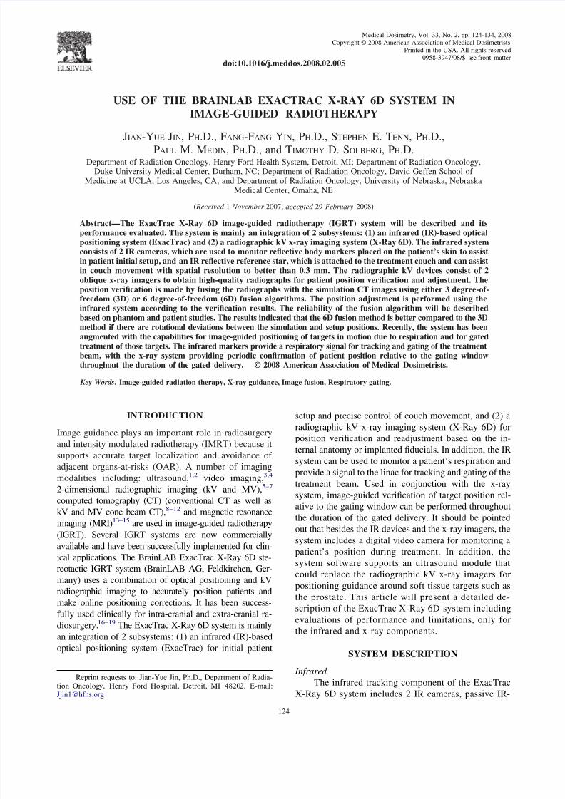
reflecting spheres placed on a patient’s surface, and a
reference device (the reference star) that contains 4 re-
flective circles (Fig. 1). The IR cameras are rigidly
mounted to a metal bar attached to the ceiling and emit
a low IR signal that is reflected and analyzed for posi-
tioning information. A 2-step calibration procedure has
been established to ensure that the IR cameras can accu-
rately determine the position of IR reflectors in the treat-
ment room. The first step corrects for distortions in the
IR system and creates a coordinate space, while the
second step provides the system with the location of
the linear accelerator (LINAC) isocenter. Studies by
Wang et al.20 have demonstrated that the position of each
IR-reflecting sphere can be determined to less than 0.3
mm. Automatic setup can then be easily achieved by
moving the couch to match the marker’s position with
those recorded in a CT image. In addition, the software
also provides rotational offsets along 3 primary axes.However, the external markers have to be positioned in a
relatively stable location to achieve accurate setup. With
the use of the reference star attached to the couch, the
couch’s movement can be precisely determined.
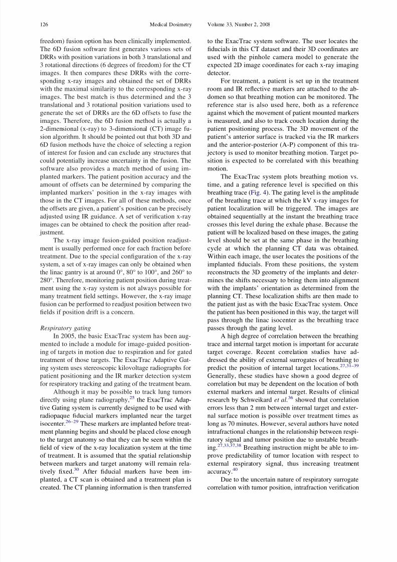
The IR system samples marker positions at a fre-
quency of 20 Hz and therefore may also be used to monitor
patient motion. Figure 2 shows an example of a patient’s
respiratory motion monitored using this system. The y-axis
is a 3-dimensional (3D) composite of the combined motion
of 5 markers placed on a patient’s chest.21 The system has
subsequently been adopted for use in respiratory correlated
imaging22 and gated radiotherapy.23,24
X-ray
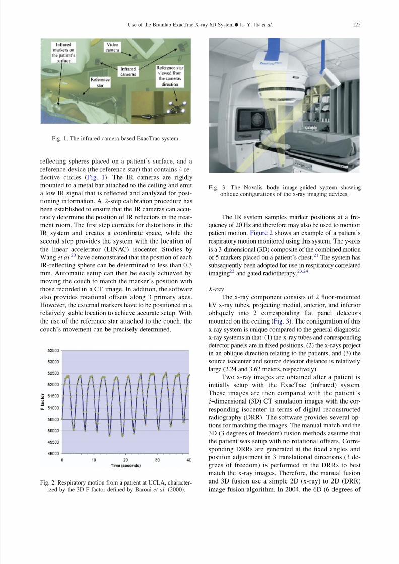
The x-ray component consists of 2 floor-mountedkV x-ray tubes, projecting medial, anterior, and inferior
obliquely into 2 corresponding flat panel detectors
mounted on the ceiling (Fig. 3). The configuration of this
x-ray system is unique compared to the general diagnostic
x-ray systems in that: (1) the x-ray tubes and corresponding
detector panels are in fixed positions, (2) the x-rays project
in an oblique direction relating to the patients, and (3) the
source isocenter and source detector distance is relatively
large (2.24 and 3.62 meters, respectively).
Two x-ray images are obtained after a patient is
initially setup with the ExacTrac (infrared) system.
These images are then compared with the patient’s3-dimensional (3D) CT simulation images with the cor-
responding isocenter in terms of digital reconstructed
radiography (DRR). The software provides several op-
tions for matching the images. The manual match and the
3D (3 degrees of freedom) fusion methods assume that
the patient was setup with no rotational offsets. Corre-
sponding DRRs are generated at the fixed angles and
position adjustment in 3 translational directions (3 de-
grees of freedom) is performed in the DRRs to best
match the x-ray images. Therefore, the manual fusion
and 3D fusion use a simple 2D (x-ray) to 2D (DRR)
image fusion algorithm. In 2004, the 6D (6 degrees of Fig. 2. Respiratory motion from a patient at UCLA, character-
ized by the 3D F-factor defined by Baroni et al. (2000).
Fig. 1. The infrared camera-based ExacTrac system.
Fig. 3. The Novalis body image-guided system showingoblique configurations of the x-ray imaging devices.
Use of the Brainlab ExacTrac X-ray 6D System ● J.- Y. JIN et al. 125
8/8/2019 Medical Dosimetry p124
http://slidepdf.com/reader/full/medical-dosimetry-p124 3/11
freedom) fusion option has been clinically implemented.
The 6D fusion software first generates various sets of
DRRs with position variations in both 3 translational and
3 rotational directions (6 degrees of freedom) for the CT
images. It then compares these DRRs with the corre-
sponding x-ray images and obtained the set of DRRs
with the maximal similarity to the corresponding x-ray
images. The best match is thus determined and the 3translational and 3 rotational position variations used to
generate the set of DRRs are the 6D offsets to fuse the
images. Therefore, the 6D fusion method is actually a
2-dimensional (x-ray) to 3-dimensional (CT) image fu-
sion algorithm. It should be pointed out that both 3D and
6D fusion methods have the choice of selecting a region
of interest for fusion and can exclude any structures that
could potentially increase uncertainty in the fusion. The
software also provides a match method of using im-
planted markers. The patient position accuracy and the
amount of offsets can be determined by comparing the
implanted markers’ position in the x-ray images with
those in the CT images. For all of these methods, once
the offsets are given, a patient’s position can be precisely
adjusted using IR guidance. A set of verification x-ray
images can be obtained to check the position after read-
justment.
The x-ray image fusion-guided position readjust-
ment is usually performed once for each fraction before
treatment. Due to the special configuration of the x-ray
system, a set of x-ray images can only be obtained when
the linac gantry is at around 0°, 80° to 100°, and 260° to
280°. Therefore, monitoring patient position during treat-
ment using the x-ray system is not always possible for
many treatment field settings. However, the x-ray imagefusion can be performed to readjust position between two
fields if position drift is a concern.
Respiratory gating
In 2005, the basic ExacTrac system has been aug-
mented to include a module for image-guided position-
ing of targets in motion due to respiration and for gated
treatment of those targets. The ExacTrac Adaptive Gat-
ing system uses stereoscopic kilovoltage radiographs for
patient positioning and the IR marker detection system
for respiratory tracking and gating of the treatment beam.
Although it may be possible to track lung tumorsdirectly using plane radiography,25 the ExacTrac Adap-
tive Gating system is currently designed to be used with
radiopaque fiducial markers implanted near the target
isocenter.26–29 These markers are implanted before treat-
ment planning begins and should be placed close enough
to the target anatomy so that they can be seen within the
field of view of the x-ray localization system at the time
of treatment. It is assumed that the spatial relationship
between markers and target anatomy will remain rela-
tively fixed.30 After fiducial markers have been im-
planted, a CT scan is obtained and a treatment plan is
created. The CT planning information is then transferred
to the ExacTrac system software. The user locates the
fiducials in this CT dataset and their 3D coordinates are
used with the pinhole camera model to generate the
expected 2D image coordinates for each x-ray imaging
detector.
For treatment, a patient is set up in the treatment
room and IR reflective markers are attached to the ab-
domen so that breathing motion can be monitored. Thereference star is also used here, both as a reference
against which the movement of patient mounted markers
is measured, and also to track couch location during the
patient positioning process. The 3D movement of the
patient’s anterior surface is tracked via the IR markers
and the anterior-posterior (A-P) component of this tra-
jectory is used to monitor breathing motion. Target po-
sition is expected to be correlated with this breathing
motion.
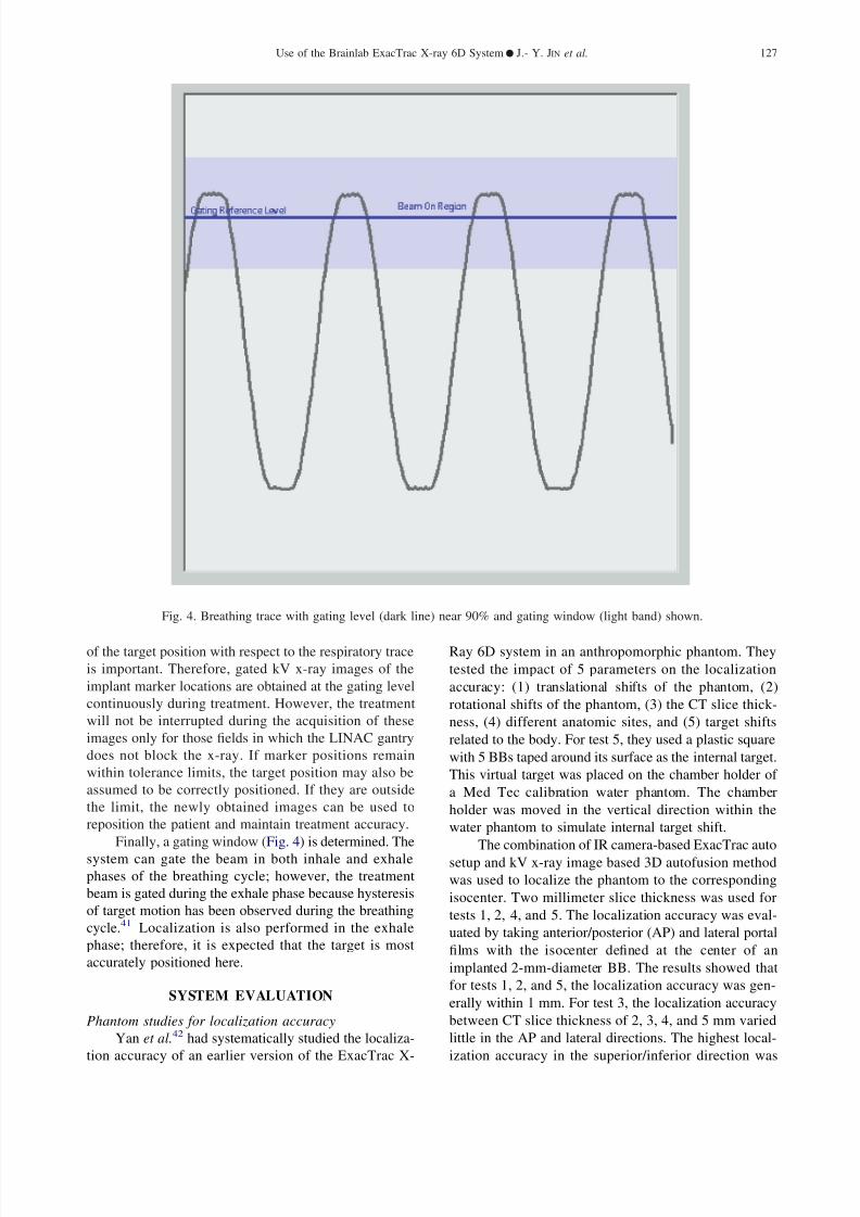
The ExacTrac system plots breathing motion vs.
time, and a gating reference level is specified on this
breathing trace (Fig. 4). The gating level is the amplitude
of the breathing trace at which the kV x-ray images for
patient localization will be triggered. The images are
obtained sequentially at the instant the breathing trace
crosses this level during the exhale phase. Because the
patient will be localized based on these images, the gating
level should be set at the same phase in the breathing
cycle at which the planning CT data was obtained.
Within each image, the user locates the positions of the
implanted fiducials. From these positions, the system
reconstructs the 3D geometry of the implants and deter-
mines the shifts necessary to bring them into alignment
with the implants’ orientation as determined from the
planning CT. These localization shifts are then made tothe patient just as with the basic ExacTrac system. Once
the patient has been positioned in this way, the target will
pass through the linac isocenter as the breathing trace
passes through the gating level.
A high degree of correlation between the breathing
trace and internal target motion is important for accurate
target coverage. Recent correlation studies have ad-
dressed the ability of external surrogates of breathing to
predict the position of internal target locations.27,31–39
Generally, these studies have shown a good degree of
correlation but may be dependent on the location of both
external markers and internal target. Results of clinicalresearch by Schweikard et al.36 showed that correlation
errors less than 2 mm between internal target and exter-
nal surface motion is possible over treatment times as
long as 70 minutes. However, several authors have noted
intrafractional changes in the relationship between respi-
ratory signal and tumor position due to unstable breath-
ing.27,33,37,38 Breathing instruction might be able to im-
prove predictability of tumor location with respect to
external respiratory signal, thus increasing treatment
accuracy.40
Due to the uncertain nature of respiratory surrogate
correlation with tumor position, intrafraction verification
Medical Dosimetry Volume 33, Number 2, 2008126
8/8/2019 Medical Dosimetry p124
http://slidepdf.com/reader/full/medical-dosimetry-p124 4/11
of the target position with respect to the respiratory trace
is important. Therefore, gated kV x-ray images of the
implant marker locations are obtained at the gating level
continuously during treatment. However, the treatment
will not be interrupted during the acquisition of these
images only for those fields in which the LINAC gantry
does not block the x-ray. If marker positions remain
within tolerance limits, the target position may also be
assumed to be correctly positioned. If they are outside
the limit, the newly obtained images can be used to
reposition the patient and maintain treatment accuracy.
Finally, a gating window (Fig. 4) is determined. The
system can gate the beam in both inhale and exhale
phases of the breathing cycle; however, the treatment
beam is gated during the exhale phase because hysteresis
of target motion has been observed during the breathing
cycle.41 Localization is also performed in the exhale
phase; therefore, it is expected that the target is most
accurately positioned here.
SYSTEM EVALUATION
Phantom studies for localization accuracy
Yan et al.42 had systematically studied the localiza-
tion accuracy of an earlier version of the ExacTrac X-
Ray 6D system in an anthropomorphic phantom. They
tested the impact of 5 parameters on the localization
accuracy: (1) translational shifts of the phantom, (2)
rotational shifts of the phantom, (3) the CT slice thick-
ness, (4) different anatomic sites, and (5) target shifts
related to the body. For test 5, they used a plastic square
with 5 BBs taped around its surface as the internal target.
This virtual target was placed on the chamber holder of
a Med Tec calibration water phantom. The chamber
holder was moved in the vertical direction within the
water phantom to simulate internal target shift.
The combination of IR camera-based ExacTrac auto
setup and kV x-ray image based 3D autofusion method
was used to localize the phantom to the corresponding
isocenter. Two millimeter slice thickness was used for
tests 1, 2, 4, and 5. The localization accuracy was eval-
uated by taking anterior/posterior (AP) and lateral portal
films with the isocenter defined at the center of an
implanted 2-mm-diameter BB. The results showed that
for tests 1, 2, and 5, the localization accuracy was gen-
erally within 1 mm. For test 3, the localization accuracy
between CT slice thickness of 2, 3, 4, and 5 mm varied
little in the AP and lateral directions. The highest local-
ization accuracy in the superior/inferior direction was
Fig. 4. Breathing trace with gating level (dark line) near 90% and gating window (light band) shown.
Use of the Brainlab ExacTrac X-ray 6D System ● J.- Y. JIN et al. 127
8/8/2019 Medical Dosimetry p124
http://slidepdf.com/reader/full/medical-dosimetry-p124 5/11
achieved with the 2-mm slice thickness. For test 4, the
localization accuracy in the head-and-neck region was
better than in the thoracic and pelvis regions, most likely
because the x-ray image quality was better.
Many factors have to be considered to interpret
these results. The LINAC isocenter shifts slightly when
the gantry rotates from the AP direction to a lateral
direction. The agreement between the radiation isocenter
and the isocenter defined by the wall-mounted lasers has
a tolerance of about 0.7 mm, as demonstrated by the
routine Winston-Lutz test. The evaluation method used
in this study was not able to detect localization accuracy
better than 0.7 mm; therefore, the observation that local-
ization accuracy does not vary significantly with CT-
slice thickness is likely due to a limitation of the evalu-
ation method.
The results showed excellent localization accuracy
for phantom with rotational shifts. This is because the
phantom is a rigid object, and the external marker setup
method could detect potential rotational shifts and made
the correction. Clinically, a patient’s contour can change
between setup and simulation and the external markers
may be placed in locations with motion resulting in
rotational and translational errors during the first step of
the positioning procedure. This study also tested the
localization accuracy in a scenario where 1 of 5 internal
markers was shifted 2 cm, and found that the localization
accuracy was degraded to less than 1.5 mm.42 This
suggests that the 3D fusion localization method could not
achieve desirable accuracy even in a rigid phantom if
rotational and translational error existed when the x-rays
were taken.
Recently, the 6D fusion localization software taking
into account the rotational errors was clinically released.
Jin et al.43 have studied the accuracy of this localization
method in a phantom. Eight BBs of 2-mm diameter were
inserted into different locations of a head phantom. One
of the BBs was used as the isocenter, while the rest of the
BBs served as the implanted markers. Both 2- and 3-mm
CT slices were studied. The head phantom was placed
intentionally with certain rotational and translational
shifts. Localization methods using 3D fusion, 6D fusion,
and implanted markers were used. For both 3D and 6D
fusions, the image areas with implanted BBs were ex-
cluded for the fusion. The localization methods were
repeated 8 times at different locations, with the isocenter
placed at the center of different BBs. Localization accu-
racy was evaluated using the portal film method reported
by Yan et al.42 The results from the implanted marker
localization study were used as an additional standard to
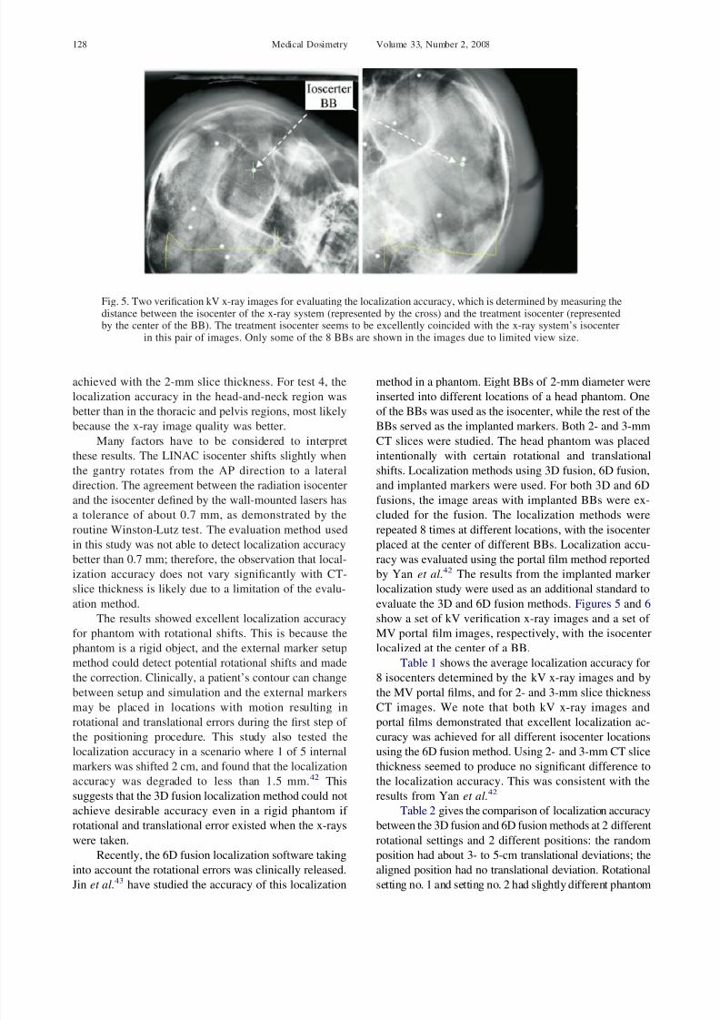
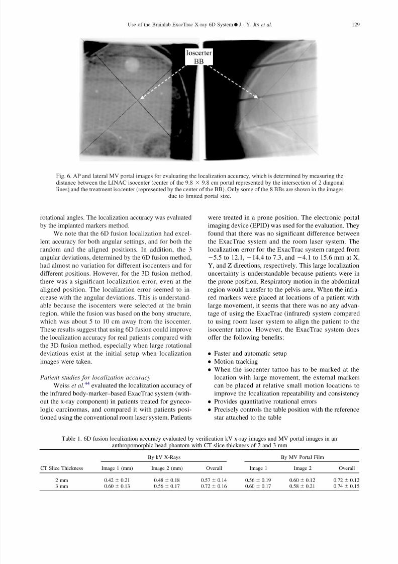
evaluate the 3D and 6D fusion methods. Figures 5 and 6
show a set of kV verification x-ray images and a set of
MV portal film images, respectively, with the isocenter
localized at the center of a BB.
Table 1 shows the average localization accuracy for
8 isocenters determined by the kV x-ray images and by
the MV portal films, and for 2- and 3-mm slice thickness
CT images. We note that both kV x-ray images and
portal films demonstrated that excellent localization ac-
curacy was achieved for all different isocenter locations
using the 6D fusion method. Using 2- and 3-mm CT slice
thickness seemed to produce no significant difference to
the localization accuracy. This was consistent with the
results from Yan et al.42
Table 2 gives the comparison of localization accuracy
between the 3D fusion and 6D fusion methods at 2 different
rotational settings and 2 different positions: the random
position had about 3- to 5-cm translational deviations; the
aligned position had no translational deviation. Rotational
setting no. 1 and setting no. 2 had slightly different phantom
Fig. 5. Two verification kV x-ray images for evaluating the localization accuracy, which is determined by measuring thedistance between the isocenter of the x-ray system (represented by the cross) and the treatment isocenter (representedby the center of the BB). The treatment isocenter seems to be excellently coincided with the x-ray system’s isocenter
in this pair of images. Only some of the 8 BBs are shown in the images due to limited view size.
Medical Dosimetry Volume 33, Number 2, 2008128
8/8/2019 Medical Dosimetry p124
http://slidepdf.com/reader/full/medical-dosimetry-p124 6/11
rotational angles. The localization accuracy was evaluated
by the implanted markers method.
We note that the 6D fusion localization had excel-
lent accuracy for both angular settings, and for both the
random and the aligned positions. In addition, the 3
angular deviations, determined by the 6D fusion method,
had almost no variation for different isocenters and for
different positions. However, for the 3D fusion method,
there was a significant localization error, even at the
aligned position. The localization error seemed to in-
crease with the angular deviations. This is understand-able because the isocenters were selected at the brain
region, while the fusion was based on the bony structure,
which was about 5 to 10 cm away from the isocenter.
These results suggest that using 6D fusion could improve
the localization accuracy for real patients compared with
the 3D fusion method, especially when large rotational
deviations exist at the initial setup when localization
images were taken.
Patient studies for localization accuracy
Weiss et al.44 evaluated the localization accuracy of
the infrared body-marker–based ExacTrac system (with-out the x-ray component) in patients treated for gyneco-
logic carcinomas, and compared it with patients posi-
tioned using the conventional room laser system. Patients
were treated in a prone position. The electronic portal
imaging device (EPID) was used for the evaluation. They
found that there was no significant difference between
the ExacTrac system and the room laser system. The
localization error for the ExacTrac system ranged from
5.5 to 12.1, 14.4 to 7.3, and 4.1 to 15.6 mm at X,
Y, and Z directions, respectively. This large localization
uncertainty is understandable because patients were in
the prone position. Respiratory motion in the abdominal
region would transfer to the pelvis area. When the infra-
red markers were placed at locations of a patient withlarge movement, it seems that there was no any advan-
tage of using the ExacTrac (infrared) system compared
to using room laser system to align the patient to the
isocenter tattoo. However, the ExacTrac system does
offer the following benefits:
● Faster and automatic setup
● Motion tracking
● When the isocenter tattoo has to be marked at the
location with large movement, the external markers
can be placed at relative small motion locations to
improve the localization repeatability and consistency● Provides quantitative rotational errors
● Precisely controls the table position with the reference
star attached to the table
Table 1. 6D fusion localization accuracy evaluated by verification kV x-ray images and MV portal images in ananthropomorphic head phantom with CT slice thickness of 2 and 3 mm
CT Slice Thickness
By kV X-Rays By MV Portal Film
Image 1 (mm) Image 2 (mm) Overall Image 1 Image 2 Overall
2 mm 0.42 0.21 0.48 0.18 0.57 0.14 0.56 0.19 0.60 0.12 0.72 0.123 mm 0.60 0.13 0.56 0.17 0.72 0.16 0.60 0.17 0.58 0.21 0.74 0.15
Fig. 6. AP and lateral MV portal images for evaluating the localization accuracy, which is determined by measuring thedistance between the LINAC isocenter (center of the 9.8 9.8 cm portal represented by the intersection of 2 diagonallines) and the treatment isocenter (represented by the center of the BB). Only some of the 8 BBs are shown in the images
due to limited portal size.
Use of the Brainlab ExacTrac X-ray 6D System ● J.- Y. JIN et al. 129
8/8/2019 Medical Dosimetry p124
http://slidepdf.com/reader/full/medical-dosimetry-p124 7/11
Yin et al. reported the localization accuracy for 25
spine patients using the combination of ExacTrac and 3D
image fusion localization method.45 The average accu-
racy for the 25 patients was reported to be 0.7 0.7,
0.8 0.9, and 0.9 0.5 mm at anterior-posterior,
left-right, and superior-inferior directions, respectively,
with an overall average of 1.6 0.9 mm. This result was
consistent with the accuracy demonstrated in the phan-
tom study. Note that the data were acquired and analyzed
based on pseudo-rigid vertebral body with a stable pa-
tient immobilization device. The errors reported here for
the portal films did not include linac isocenter inconsis-
tency, which was in the order of about 0.7 mm, and the
uncertainty of defining bony land markers in DRRs and
portal films, especially for the MV portal films, which
usually have poor image quality. The error defined was
also strictly for the isocenter and did not include any
deviations related to rotations around the isocenter.
Jin et al. have studied the localization accuracy of
6D fusion localization method in patients for both cranial
and spinal lesions.43,46 Verification kV x-ray images and
MV portal film after localization were taken and com-
pared to the corresponding DRRs. The bony structures
were clearly seen in cranial kV x-ray images for allcranial patients. Both manual match and automatic 6D
fusion match was used to evaluate the localization accu-
racy. Preliminary results suggested that about 1-mm lo-
calization accuracy could be achieved for the cranial
patients. The 6D fusion localization method was also
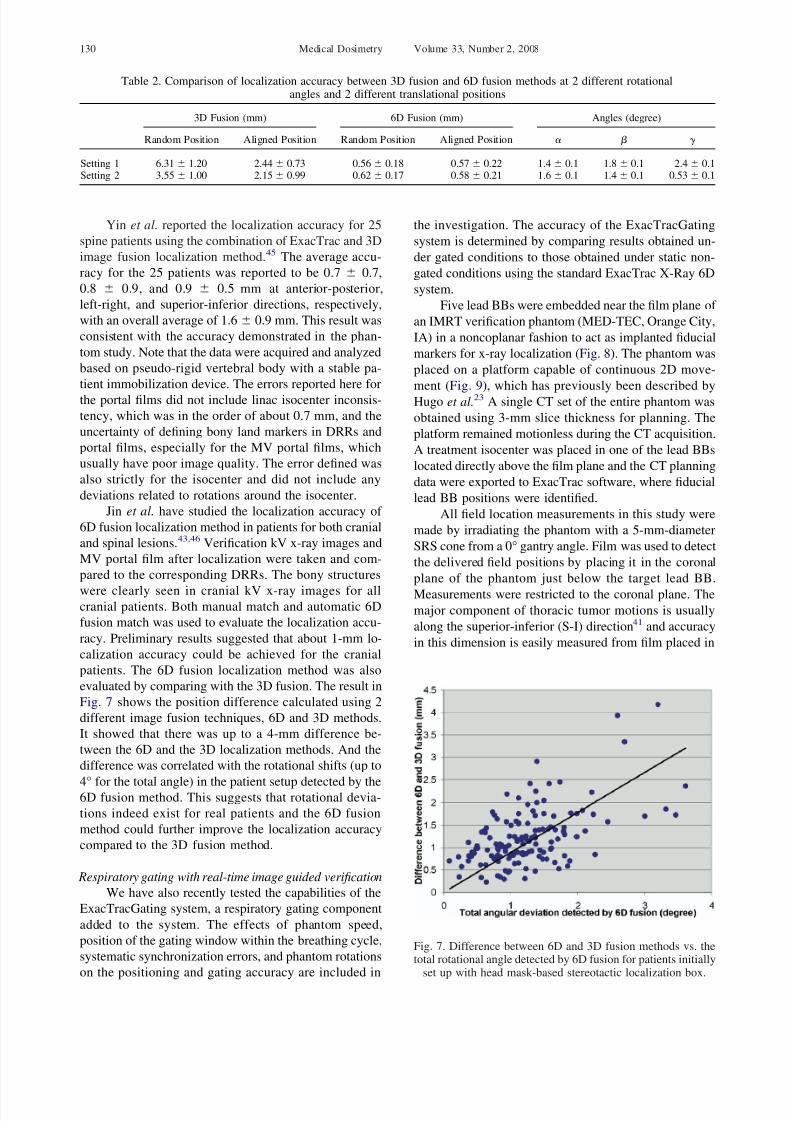
evaluated by comparing with the 3D fusion. The result in
Fig. 7 shows the position difference calculated using 2
different image fusion techniques, 6D and 3D methods.
It showed that there was up to a 4-mm difference be-
tween the 6D and the 3D localization methods. And the
difference was correlated with the rotational shifts (up to
4° for the total angle) in the patient setup detected by the6D fusion method. This suggests that rotational devia-
tions indeed exist for real patients and the 6D fusion
method could further improve the localization accuracy
compared to the 3D fusion method.
Respiratory gating with real-time image guided verification
We have also recently tested the capabilities of the
ExacTracGating system, a respiratory gating component
added to the system. The effects of phantom speed,
position of the gating window within the breathing cycle,
systematic synchronization errors, and phantom rotations
on the positioning and gating accuracy are included in
the investigation. The accuracy of the ExacTracGating
system is determined by comparing results obtained un-
der gated conditions to those obtained under static non-
gated conditions using the standard ExacTrac X-Ray 6D
system.
Five lead BBs were embedded near the film plane of
an IMRT verification phantom (MED-TEC, Orange City,
IA) in a noncoplanar fashion to act as implanted fiducial
markers for x-ray localization (Fig. 8). The phantom was
placed on a platform capable of continuous 2D move-
ment (Fig. 9), which has previously been described by
Hugo et al.23 A single CT set of the entire phantom was
obtained using 3-mm slice thickness for planning. The
platform remained motionless during the CT acquisition.
A treatment isocenter was placed in one of the lead BBs
located directly above the film plane and the CT planning
data were exported to ExacTrac software, where fiducial
lead BB positions were identified.
All field location measurements in this study were
made by irradiating the phantom with a 5-mm-diameter
SRS cone from a 0° gantry angle. Film was used to detect
the delivered field positions by placing it in the coronal
plane of the phantom just below the target lead BB.
Measurements were restricted to the coronal plane. Themajor component of thoracic tumor motions is usually
along the superior-inferior (S-I) direction41 and accuracy
in this dimension is easily measured from film placed in
Table 2. Comparison of localization accuracy between 3D fusion and 6D fusion methods at 2 different rotationalangles and 2 different translational positions
3D Fusion (mm) 6D Fusion (mm) Angles (degree)
Random Position Aligned Position Random Position Aligned Position
Setting 1 6.31 1.20 2.44 0.73 0.56 0.18 0.57 0.22 1.4 0.1 1.8 0.1 2.4 0.1Setting 2 3.55 1.00 2.15 0.99 0.62 0.17 0.58 0.21 1.6 0.1 1.4 0.1 0.53 0.1
Fig. 7. Difference between 6D and 3D fusion methods vs. thetotal rotational angle detected by 6D fusion for patients initially
set up with head mask-based stereotactic localization box.
Medical Dosimetry Volume 33, Number 2, 2008130
8/8/2019 Medical Dosimetry p124
http://slidepdf.com/reader/full/medical-dosimetry-p124 8/11
the coronal plane. Five pins in the phantom mark the film
and allow exposed films to be registered into a common
reference frame for comparison. Field center or mass
locations were used to determine accuracy.
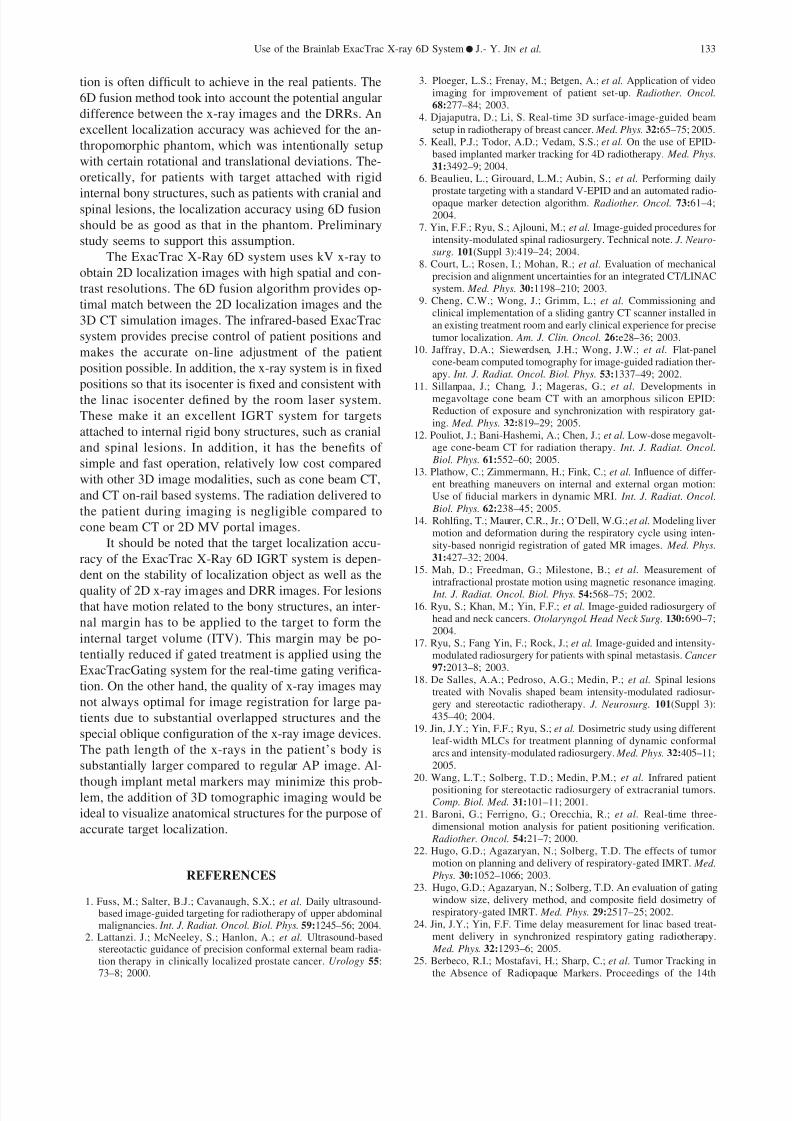
The effect of phantom speed was investigated using
2 different 2D motions moving in the sagittal plane (Fig.
10). The first motion (10A) had a period of 5.7 seconds,
an S-I range of 1.8 cm, and an A-P range of 1.2 cm. The
second motion (10B) had the same displacement ranges
as the first but had a shorter period of 3.6 seconds. Target
position under gating conditions, represented by the po-
sition of the target BB in the film, was measured withgating levels of 10%, 50%, and 90% of the breathing
trace peak-to-peak height, and was compared with the
corresponding position under static condition. A sym-
metric gating window of 20% was placed around the
gating level for every condition except for the 50%
gating level and fast motion combination, for which a
gating window of 30% was used. A 30% window was
used for the specified condition because the beam-on
time interval was too short for the LINAC to deliver any
radiation using a 20% window. Fields gated at the 50%
and 90% amplitude levels were not different from fields
delivered under static conditions by more than one stan-dard deviation (0.1 mm). Fields gated at 10% were offset
by approximately 1 mm. This could be because much
more radiation fluence was delivered to the target when
it was below the 10% gating level than it was above this
level (the target had the slowest motion speed when it
was at the exhale peak).
Jin and Yin24 have determined the overall system
latency in a beta version of the ExacTracGating system
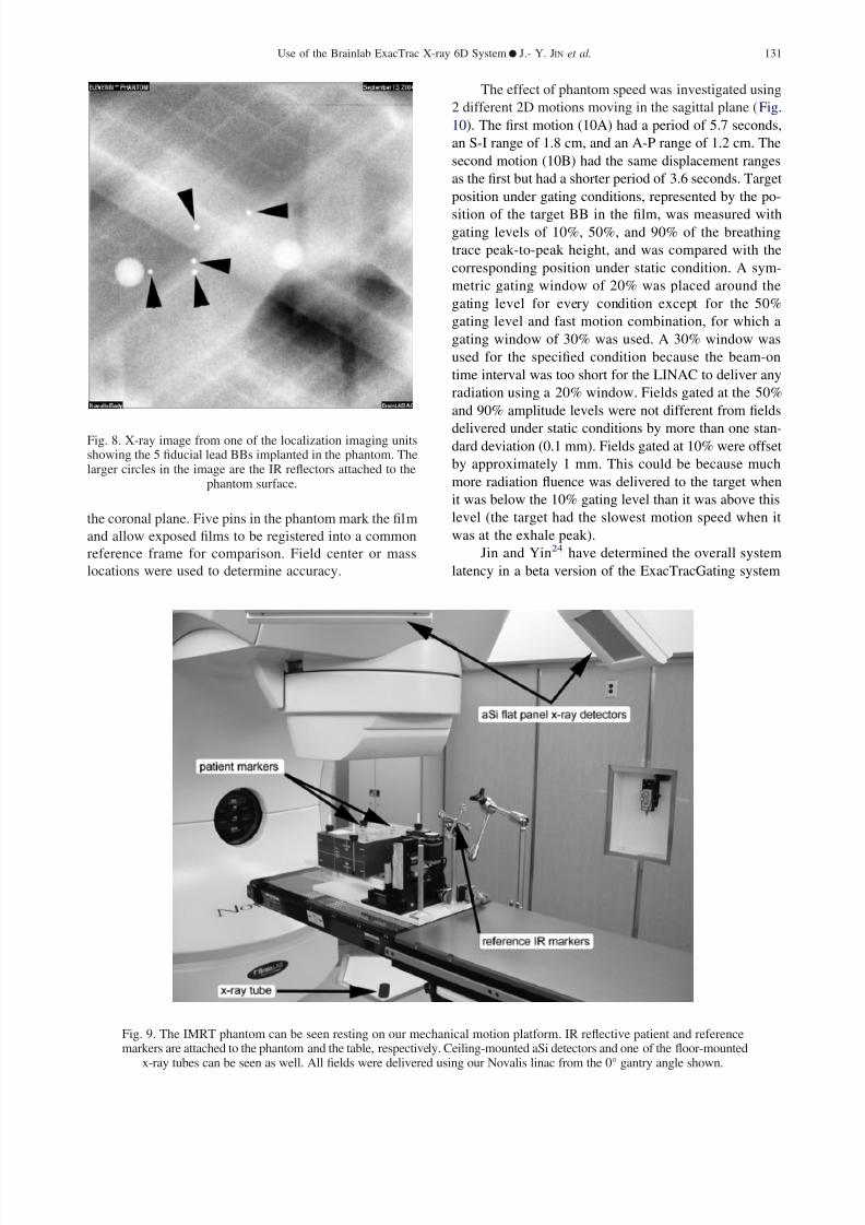
Fig. 8. X-ray image from one of the localization imaging unitsshowing the 5 fiducial lead BBs implanted in the phantom. Thelarger circles in the image are the IR reflectors attached to the
phantom surface.
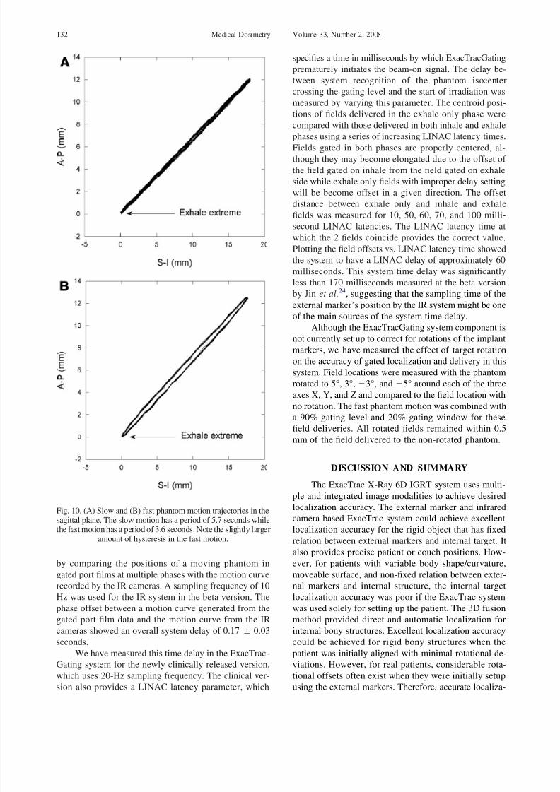
Fig. 9. The IMRT phantom can be seen resting on our mechanical motion platform. IR reflective patient and referencemarkers are attached to the phantom and the table, respectively. Ceiling-mounted aSi detectors and one of the floor-mounted
x-ray tubes can be seen as well. All fields were delivered using our Novalis linac from the 0° gantry angle shown.
Use of the Brainlab ExacTrac X-ray 6D System ● J.- Y. JIN et al. 131
8/8/2019 Medical Dosimetry p124
http://slidepdf.com/reader/full/medical-dosimetry-p124 9/11
by comparing the positions of a moving phantom in
gated port films at multiple phases with the motion curve
recorded by the IR cameras. A sampling frequency of 10
Hz was used for the IR system in the beta version. The
phase offset between a motion curve generated from the
gated port film data and the motion curve from the IR
cameras showed an overall system delay of 0.17 0.03
seconds.
We have measured this time delay in the ExacTrac-
Gating system for the newly clinically released version,
which uses 20-Hz sampling frequency. The clinical ver-
sion also provides a LINAC latency parameter, which
specifies a time in milliseconds by which ExacTracGating
prematurely initiates the beam-on signal. The delay be-
tween system recognition of the phantom isocenter
crossing the gating level and the start of irradiation was
measured by varying this parameter. The centroid posi-
tions of fields delivered in the exhale only phase were
compared with those delivered in both inhale and exhale
phases using a series of increasing LINAC latency times.Fields gated in both phases are properly centered, al-
though they may become elongated due to the offset of
the field gated on inhale from the field gated on exhale
side while exhale only fields with improper delay setting
will be become offset in a given direction. The offset
distance between exhale only and inhale and exhale
fields was measured for 10, 50, 60, 70, and 100 milli-
second LINAC latencies. The LINAC latency time at
which the 2 fields coincide provides the correct value.
Plotting the field offsets vs. LINAC latency time showed
the system to have a LINAC delay of approximately 60
milliseconds. This system time delay was significantly
less than 170 milliseconds measured at the beta version
by Jin et al.24, suggesting that the sampling time of the
external marker’s position by the IR system might be one
of the main sources of the system time delay.
Although the ExacTracGating system component is
not currently set up to correct for rotations of the implant
markers, we have measured the effect of target rotation
on the accuracy of gated localization and delivery in this
system. Field locations were measured with the phantom
rotated to 5°, 3°, 3°, and 5° around each of the three
axes X, Y, and Z and compared to the field location with
no rotation. The fast phantom motion was combined with
a 90% gating level and 20% gating window for thesefield deliveries. All rotated fields remained within 0.5
mm of the field delivered to the non-rotated phantom.
DISCUSSION AND SUMMARY
The ExacTrac X-Ray 6D IGRT system uses multi-
ple and integrated image modalities to achieve desired
localization accuracy. The external marker and infrared
camera based ExacTrac system could achieve excellent
localization accuracy for the rigid object that has fixed
relation between external markers and internal target. It
also provides precise patient or couch positions. How-ever, for patients with variable body shape/curvature,
moveable surface, and non-fixed relation between exter-
nal markers and internal structure, the internal target
localization accuracy was poor if the ExacTrac system
was used solely for setting up the patient. The 3D fusion
method provided direct and automatic localization for
internal bony structures. Excellent localization accuracy
could be achieved for rigid bony structures when the
patient was initially aligned with minimal rotational de-
viations. However, for real patients, considerable rota-
tional offsets often exist when they were initially setup
using the external markers. Therefore, accurate localiza-
Fig. 10. (A) Slow and (B) fast phantom motion trajectories in thesagittal plane. The slow motion has a period of 5.7 seconds whilethe fast motion has a period of 3.6 seconds. Note the slightly larger
amount of hysteresis in the fast motion.
Medical Dosimetry Volume 33, Number 2, 2008132
8/8/2019 Medical Dosimetry p124
http://slidepdf.com/reader/full/medical-dosimetry-p124 10/11
tion is often difficult to achieve in the real patients. The
6D fusion method took into account the potential angular
difference between the x-ray images and the DRRs. An
excellent localization accuracy was achieved for the an-
thropomorphic phantom, which was intentionally setup
with certain rotational and translational deviations. The-
oretically, for patients with target attached with rigid
internal bony structures, such as patients with cranial andspinal lesions, the localization accuracy using 6D fusion
should be as good as that in the phantom. Preliminary
study seems to support this assumption.
The ExacTrac X-Ray 6D system uses kV x-ray to
obtain 2D localization images with high spatial and con-
trast resolutions. The 6D fusion algorithm provides op-
timal match between the 2D localization images and the
3D CT simulation images. The infrared-based ExacTrac
system provides precise control of patient positions and
makes the accurate on-line adjustment of the patient
position possible. In addition, the x-ray system is in fixed
positions so that its isocenter is fixed and consistent with
the linac isocenter defined by the room laser system.
These make it an excellent IGRT system for targets
attached to internal rigid bony structures, such as cranial
and spinal lesions. In addition, it has the benefits of
simple and fast operation, relatively low cost compared
with other 3D image modalities, such as cone beam CT,
and CT on-rail based systems. The radiation delivered to
the patient during imaging is negligible compared to
cone beam CT or 2D MV portal images.
It should be noted that the target localization accu-
racy of the ExacTrac X-Ray 6D IGRT system is depen-
dent on the stability of localization object as well as the
quality of 2D x-ray images and DRR images. For lesionsthat have motion related to the bony structures, an inter-
nal margin has to be applied to the target to form the
internal target volume (ITV). This margin may be po-
tentially reduced if gated treatment is applied using the
ExacTracGating system for the real-time gating verifica-
tion. On the other hand, the quality of x-ray images may
not always optimal for image registration for large pa-
tients due to substantial overlapped structures and the
special oblique configuration of the x-ray image devices.
The path length of the x-rays in the patient’s body is
substantially larger compared to regular AP image. Al-
though implant metal markers may minimize this prob-lem, the addition of 3D tomographic imaging would be
ideal to visualize anatomical structures for the purpose of
accurate target localization.
REFERENCES
1. Fuss, M.; Salter, B.J.; Cavanaugh, S.X.; et al. Daily ultrasound-based image-guided targeting for radiotherapy of upper abdominalmalignancies. Int. J. Radiat. Oncol. Biol. Phys. 59:1245–56; 2004.
2. Lattanzi. J.; McNeeley, S.; Hanlon, A.; et al. Ultrasound-basedstereotactic guidance of precision conformal external beam radia-tion therapy in clinically localized prostate cancer. Urology 55:73–8; 2000.
3. Ploeger, L.S.; Frenay, M.; Betgen, A.; et al. Application of videoimaging for improvement of patient set-up. Radiother. Oncol.
68:277–84; 2003.4. Djajaputra, D.; Li, S. Real-time 3D surface-image-guided beam
setup in radiotherapy of breast cancer. Med. Phys. 32:65–75; 2005.5. Keall, P.J.; Todor, A.D.; Vedam, S.S.; et al. On the use of EPID-
based implanted marker tracking for 4D radiotherapy. Med. Phys.
31:3492–9; 2004.6. Beaulieu, L.; Girouard, L.M.; Aubin, S.; et al. Performing daily
prostate targeting with a standard V-EPID and an automated radio-opaque marker detection algorithm. Radiother. Oncol. 73:61–4;2004.
7. Yin, F.F.; Ryu, S.; Ajlouni, M.; et al. Image-guided procedures forintensity-modulated spinal radiosurgery. Technical note. J. Neuro-
surg. 101(Suppl 3):419–24; 2004.8. Court, L.; Rosen, I.; Mohan, R.; et al. Evaluation of mechanical
precision and alignment uncertainties for an integrated CT/LINACsystem. Med. Phys. 30:1198–210; 2003.
9. Cheng, C.W.; Wong, J.; Grimm, L.; et al. Commissioning andclinical implementation of a sliding gantry CT scanner installed inan existing treatment room and early clinical experience for precisetumor localization. Am. J. Clin. Oncol. 26:e28–36; 2003.
10. Jaffray, D.A.; Siewerdsen, J.H.; Wong, J.W.; et al. Flat-panelcone-beam computed tomography for image-guided radiation ther-apy. Int. J. Radiat. Oncol. Biol. Phys. 53:1337–49; 2002.
11. Sillanpaa, J.; Chang, J.; Mageras, G.; et al. Developments inmegavoltage cone beam CT with an amorphous silicon EPID:Reduction of exposure and synchronization with respiratory gat-ing. Med. Phys. 32:819–29; 2005.
12. Pouliot, J.; Bani-Hashemi, A.; Chen, J.; et al. Low-dose megavolt-age cone-beam CT for radiation therapy. Int. J. Radiat. Oncol.
Biol. Phys. 61:552–60; 2005.13. Plathow, C.; Zimmermann, H.; Fink, C.; et al. Influence of differ-
ent breathing maneuvers on internal and external organ motion:Use of fiducial markers in dynamic MRI. Int. J. Radiat. Oncol.
Biol. Phys. 62:238–45; 2005.14. Rohlfing, T.; Maurer, C.R., Jr.; O’Dell, W.G.; et al. Modeling liver
motion and deformation during the respiratory cycle using inten-sity-based nonrigid registration of gated MR images. Med. Phys.
31:427–32; 2004.15. Mah, D.; Freedman, G.; Milestone, B.; et al. Measurement of
intrafractional prostate motion using magnetic resonance imaging. Int. J. Radiat. Oncol. Biol. Phys. 54:568–75; 2002.
16. Ryu, S.; Khan, M.; Yin, F.F.; et al. Image-guided radiosurgery of head and neck cancers. Otolaryngol. Head Neck Surg. 130:690–7;2004.
17. Ryu, S.; Fang Yin, F.; Rock, J.; et al. Image-guided and intensity-modulated radiosurgery for patients with spinal metastasis. Cancer
97:2013–8; 2003.18. De Salles, A.A.; Pedroso, A.G.; Medin, P.; et al. Spinal lesions
treated with Novalis shaped beam intensity-modulated radiosur-gery and stereotactic radiotherapy. J. Neurosurg. 101(Suppl 3):435–40; 2004.
19. Jin, J.Y.; Yin, F.F.; Ryu, S.; et al. Dosimetric study using differentleaf-width MLCs for treatment planning of dynamic conformalarcs and intensity-modulated radiosurgery. Med. Phys. 32:405–11;2005.
20. Wang, L.T.; Solberg, T.D.; Medin, P.M.; et al. Infrared patientpositioning for stereotactic radiosurgery of extracranial tumors.Comp. Biol. Med. 31:101–11; 2001.
21. Baroni, G.; Ferrigno, G.; Orecchia, R.; et al. Real-time three-dimensional motion analysis for patient positioning verification. Radiother. Oncol. 54:21–7; 2000.
22. Hugo, G.D.; Agazaryan, N.; Solberg, T.D. The effects of tumormotion on planning and delivery of respiratory-gated IMRT. Med.
Phys. 30:1052–1066; 2003.23. Hugo, G.D.; Agazaryan, N.; Solberg, T.D. An evaluation of gating
window size, delivery method, and composite field dosimetry of respiratory-gated IMRT. Med. Phys. 29:2517–25; 2002.
24. Jin, J.Y.; Yin, F.F. Time delay measurement for linac based treat-ment delivery in synchronized respiratory gating radiotherapy. Med. Phys. 32:1293–6; 2005.
25. Berbeco, R.I.; Mostafavi, H.; Sharp, C.; et al. Tumor Tracking inthe Absence of Radiopaque Markers. Proceedings of the 14th
Use of the Brainlab ExacTrac X-ray 6D System ● J.- Y. JIN et al. 133

8/8/2019 Medical Dosimetry p124
http://slidepdf.com/reader/full/medical-dosimetry-p124 11/11
International Conference on Computer Use in Radiation Therapy(ICCR). Seoul, South Korea; 2004.
26. Harada, T.; Shirato, H.; Ogura, S.; et al. Real-time tumor-trackingradiation therapy for lung carcinoma by the aid of insertion of agold marker using bronchofiberscopy. Cancer 95:1720–7; 2002.
27. Ozhasoglu, C.; Murphy, M.J. Issues in respiratory motion com-pensation during external-beam radiotherapy. Int. J. Radiat. Oncol. Biol. Phys. 52:1389–99; 2002.
28. Shirato, H.; Harada, T.; Harabayashi, T.; et al. Feasibility of insertion/implantation of 2.0-mm-diameter gold internal fiducial
markers for precise setup and real-time tumor tracking in radio-therapy. Int. J. Radiat. Oncol. Biol. Phys. 56:240–7; 2003.
29. Whyte, R.I.; Crownover, R.; Murphy, M.J.; et al. Stereotacticradiosurgery for lung tumors: Preliminary report of a phase I trial. Ann Thorac. Surg. 75:1097–10; 2003.
30. Ebe, K.; Shirato, H.; Hiyama, A.; et al. Integration of fluoroscopicreal-time tumor-tracking system and tomographic scanner on therail in the treatment room. Int. J. Radiat. Oncol. Biol. Phys.60:S604; 2004.
31. Vedam, S.S.; Kini, V.R.; Keall, P.J.; et al. Quantifying the pre-dictability of diaphragm motion during respiration with a nonin-vasive external marker. Med. Phys. 30:505–13; 2003.
32. Ahn, S.; Yi, B.; Suh, Y.; et al. A feasibility study on the predictionof tumour location in the lung from skin motion. Br. J. Radiol.77:588–96; 2004.
33. Hoisak, J.D.; Sixel, K.E.; Tirona, R.; et al. Correlation of lung
tumor motion with external surrogate indicators of respiration. Int. J. Radiat. Oncol. Biol. Phys. 60:1298–306; 2004.
34. Koch, N.; Liu, H.H.; Starkschall, G.; et al. Evaluation of internallung motion for respiratory-gated radiotherapy using MRI: PartI--correlating internal lung motion with skin fiducial motion. Int. J. Radiat. Oncol. Biol. Phys. 60:1459–72; 2004.
35. Liu, H.H.; Koch, N.; Starkschall, G.; et al. Evaluation of internallung motion for respiratory-gated radiotherapy using MRI: PartII-margin reduction of internal target volume Int. J. Radiat. Oncol.
Biol. Phys. 60:1473–83; 2004.36. Schweikard, A.; Shiomi, H.; Adler, J. Respiration tracking in
radiosurgery Med. Phys. 31:2738–41; 2004.
37. Tsunashima, Y.; Sakae, T.; Shioyama, Y.; et al. Correlation be-tween the respiratory waveform measured using a respiratory sen-
sor and 3D tumor motion in gated radiotherapy. Int. J. Radiat.
Oncol. Biol. Phys. 60:951–8; 2004.38. Berbeco, R.I.; Nishioka, S.; Shirato, H.; et al. Residual motion of
lung tumours in gated radiotherapy with external respiratory sur-rogates. Phys. Med. Biol. 50:3655–67; 2005.
39. Plathow, C.; Zimmermann, H.; Fink, C.; et al. Influence of differ-ent breathing maneuvers on internal and external organ motion:
Use of fiducial markers in dynamic MRI. Int. J. Radiat. Oncol. Biol. Phys. 62:238–45; 2005.
40. George. R.; Ramakrishnan, V.; Siebers, J.; et al. Investigation of variables affecting residual motion for respiratory gated radiother-apy. Med. Phys. 32:2124; 2005.
41. Seppenwoolde, Y.; Shirato, H.; Kitamura, K.; et al. Precise andreal-time measurement of 3D tumor motion in lung due to breath-ing and heartbeat, measured during radiotherapy. Int. J. Radiat.
Oncol. Biol. Physz. 53:822–34; 2002.
42. Yan, H.; Yin, F.F.; Kim, J.H. A phantom study on the positioningaccuracy of the Novalis Body system. Med. Phys. 30:3052–60;2003.
43. Jin, J.Y.; Ryu, S.; Faber, K.; et al. 2D/3D image fusion for accuratetarget localization and evaluation of a mask based stereotacticsystem in fractionated stereotactic radiotherapy of cranial lesions. Med. Phys. 33:4557–66; 2006.
44. Weiss, E.; Vorwerk, H.; Richter, S.; et al. Interfractional andintrafractional accuracy during radiotherapy of gynecologic carci-nomas: A comprehensive evaluation using the ExacTrac system. Int. J. Radiat. Oncol. Biol. Phys. 56:69–79; 2003.
45. Yin, F.F.; Ryu, S.; Ajlouni, M.; et al. A technique of intensity-modulated radiosurgery (IMRS) for spinal tumors. Med. Phys.
29:2815–22; 2002.46. Jin, J.Y.; Ryu, S.; Rock, J.; et al. Image-guided target localization
for stereotactic surgery: accuracy of 6D versus 3D image fusion.In: Kondziolka, D., ed. Radiosurgery (Vol. 6). Basel: Karger; 2006:50-59.
Medical Dosimetry Volume 33, Number 2, 2008134