Embed Size (px)
Citation preview
8/13/2019 Media Lecture Notes S5B1C6
http://slidepdf.com/reader/full/media-lecture-notes-s5b1c6 1/17
CompEdu HPT / S5: Aeroelasticity / B1: Introduction / C6: Important Parameters T. H. Fransson
1
AEROELASTICITY IN AXIAL-FLOWTURBOMACHINES
Torsten H. Fransson
Book 1:INTRODUCTION
Chapter 6:
Important Parameters
SUMMARY
The aeroelastic behavior of turbomachine bladed disks is very complex. Manyphysical parameters are significant, ranging from the overall steady-state flowcharacteristics to small details related to wear of certain parts of the structure overthe life-time of the machine.
This section aims at identifying some of the most important parameters, mainly froman unsteady aerodynamic perspective, related to the aerodynamic ‘forcing function’acting on the blades.
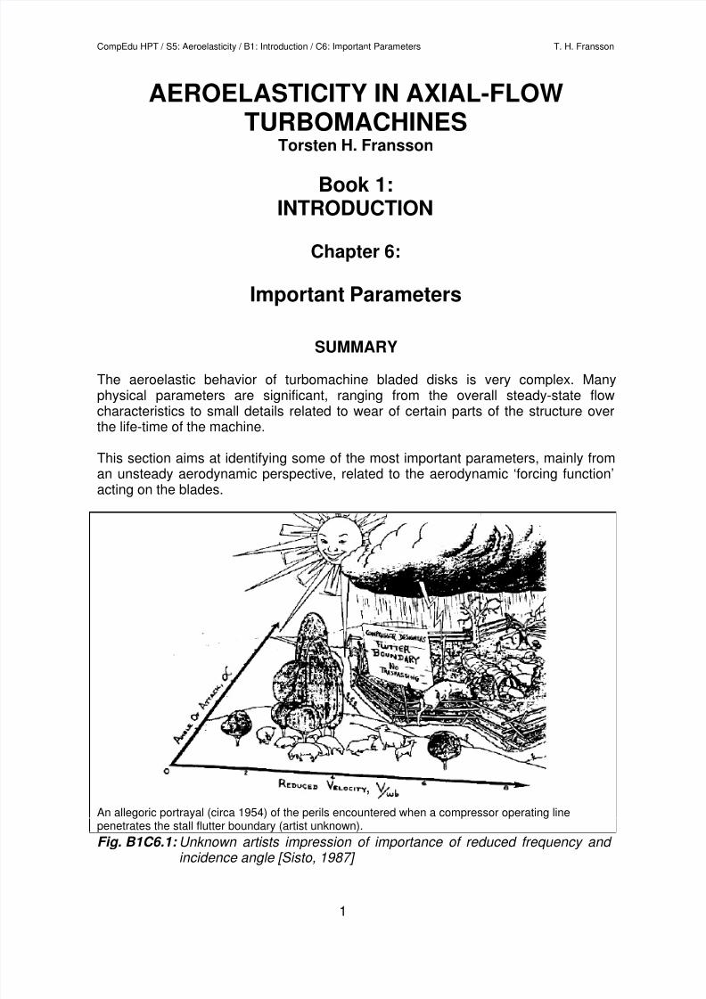
An allegoric portrayal (circa 1954) of the perils encountered when a compressor operating linepenetrates the stall flutter boundary (artist unknown).
Fig. B1C6.1: Unknown artists impression of importance of reduced frequency and incidence angle [Sisto, 1987]
8/13/2019 Media Lecture Notes S5B1C6
http://slidepdf.com/reader/full/media-lecture-notes-s5b1c6 2/17
CompEdu HPT / S5: Aeroelasticity / B1: Introduction / C6: Important Parameters T. H. Fransson
2
IMPORTANT PARAMETERS
Bladed disk assembly vibrations have been encountered for many years. Themechanism behind forced response is in theory known, and significant work isperformed during any design phase to avoid integral engine order excitations since
the pioneering work by Campbell [1924, 1925]. The problem of self-excited vibrationsin turbomachines was made evident somewhat later, mainly during the developmentof jet engines in the 1940’s. When it manifested itself, the main parameters wereidentified as the reduced velocity (=inverse of reduced frequency) and incidenceangle (Fig. B1C6.1). Although aeroelastic phenomena have thus been around formany years, forced response, flutter, any kind of non-integral vibrations, etc., arelikely to remain important issues for the turbomachine designer in the future. Themain reason for this is the fact that the detailed physical aspects of the highlyinterdisciplinary field of aeroelasticity are not known. Furthermore, the phenomenonis significantly influenced by several different parameters. A small change in some ofthese can considerably alter the characteristics of the fluid/bladed-disk interaction,
whereas some are such that minor gradual changes will appear until the system hasreached a condition such that a failure suddenly happens.
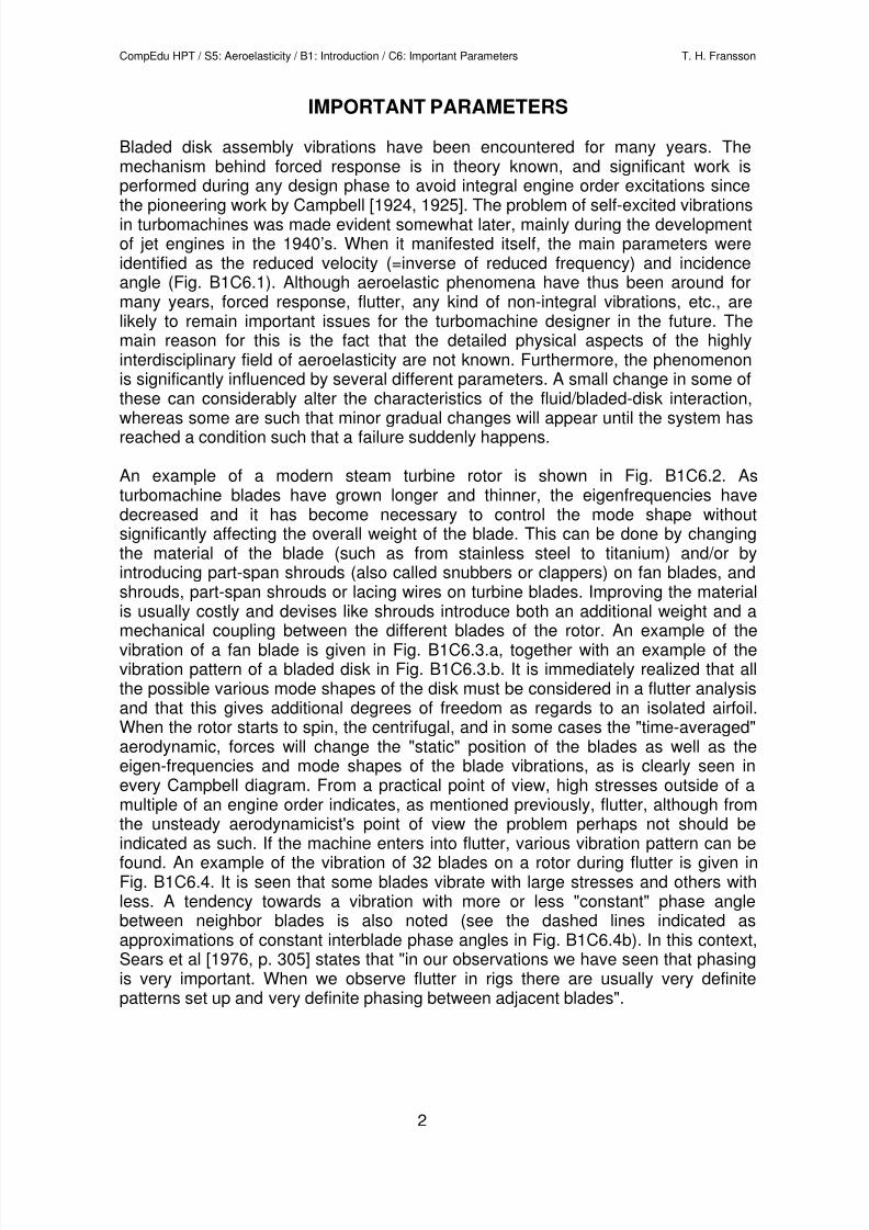
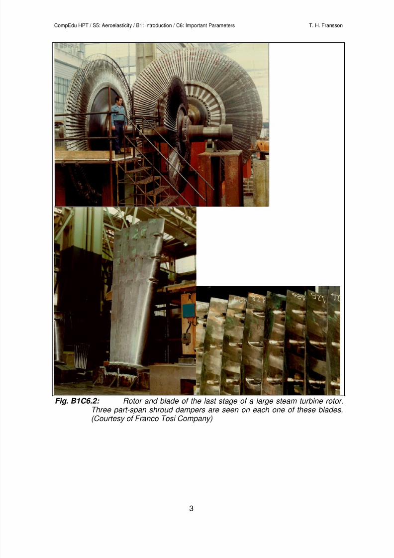
An example of a modern steam turbine rotor is shown in Fig. B1C6.2. Asturbomachine blades have grown longer and thinner, the eigenfrequencies havedecreased and it has become necessary to control the mode shape withoutsignificantly affecting the overall weight of the blade. This can be done by changingthe material of the blade (such as from stainless steel to titanium) and/or byintroducing part-span shrouds (also called snubbers or clappers) on fan blades, andshrouds, part-span shrouds or lacing wires on turbine blades. Improving the materialis usually costly and devises like shrouds introduce both an additional weight and amechanical coupling between the different blades of the rotor. An example of thevibration of a fan blade is given in Fig. B1C6.3.a, together with an example of thevibration pattern of a bladed disk in Fig. B1C6.3.b. It is immediately realized that allthe possible various mode shapes of the disk must be considered in a flutter analysisand that this gives additional degrees of freedom as regards to an isolated airfoil.When the rotor starts to spin, the centrifugal, and in some cases the "time-averaged"aerodynamic, forces will change the "static" position of the blades as well as theeigen-frequencies and mode shapes of the blade vibrations, as is clearly seen inevery Campbell diagram. From a practical point of view, high stresses outside of amultiple of an engine order indicates, as mentioned previously, flutter, although from
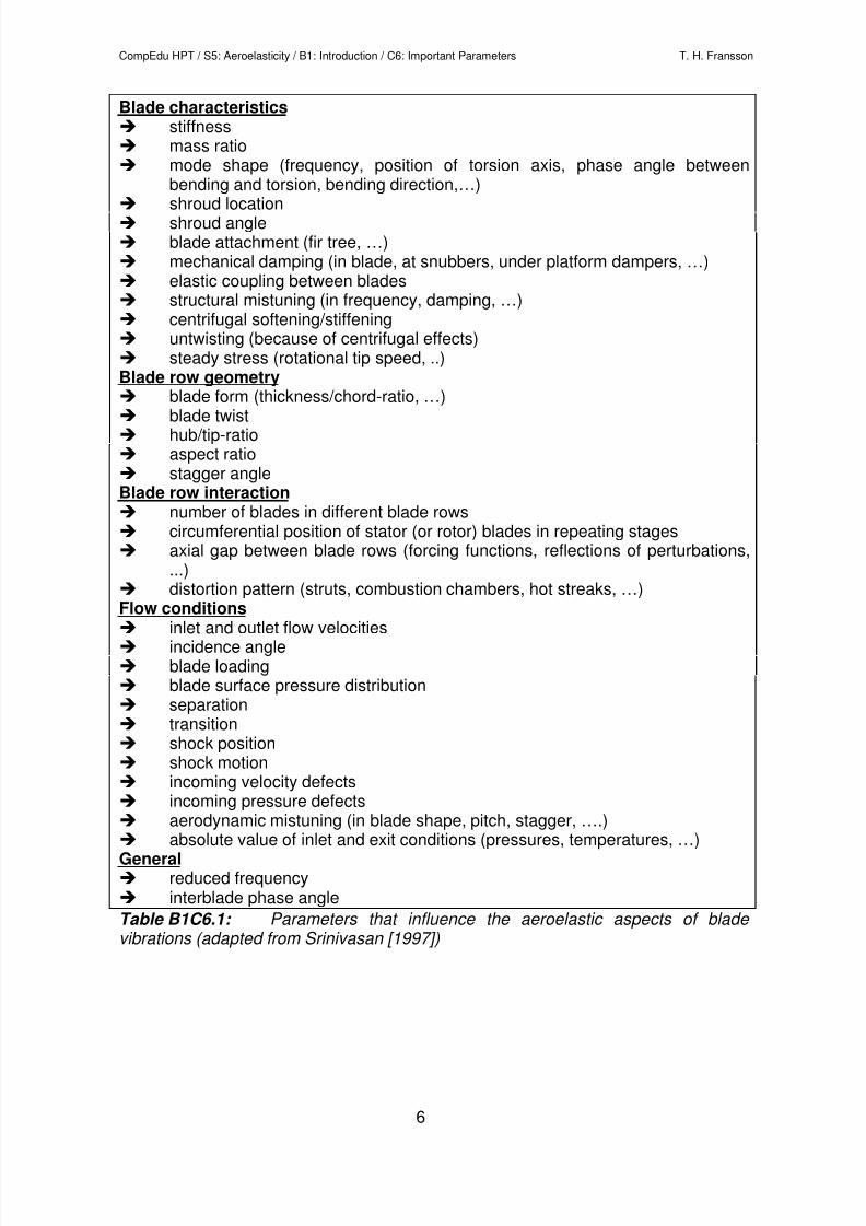
the unsteady aerodynamicist's point of view the problem perhaps not should beindicated as such. If the machine enters into flutter, various vibration pattern can befound. An example of the vibration of 32 blades on a rotor during flutter is given inFig. B1C6.4. It is seen that some blades vibrate with large stresses and others withless. A tendency towards a vibration with more or less "constant" phase anglebetween neighbor blades is also noted (see the dashed lines indicated asapproximations of constant interblade phase angles in Fig. B1C6.4b). In this context,Sears et al [1976, p. 305] states that "in our observations we have seen that phasingis very important. When we observe flutter in rigs there are usually very definitepatterns set up and very definite phasing between adjacent blades".
8/13/2019 Media Lecture Notes S5B1C6
http://slidepdf.com/reader/full/media-lecture-notes-s5b1c6 3/17
CompEdu HPT / S5: Aeroelasticity / B1: Introduction / C6: Important Parameters T. H. Fransson
3
Fig. B1C6.2: Rotor and blade of the last stage of a large steam turbine rotor.Three part-span shroud dampers are seen on each one of these blades.(Courtesy of Franco Tosi Company)
8/13/2019 Media Lecture Notes S5B1C6
http://slidepdf.com/reader/full/media-lecture-notes-s5b1c6 4/17
CompEdu HPT / S5: Aeroelasticity / B1: Introduction / C6: Important Parameters T. H. Fransson
4
a: Example of blade vibration mode shape.
b: Double pulse hologram of a vibrating fan blade [Volvo Flygmotor, 1990, p. 20].
8/13/2019 Media Lecture Notes S5B1C6
http://slidepdf.com/reader/full/media-lecture-notes-s5b1c6 5/17
CompEdu HPT / S5: Aeroelasticity / B1: Introduction / C6: Important Parameters T. H. Fransson
5
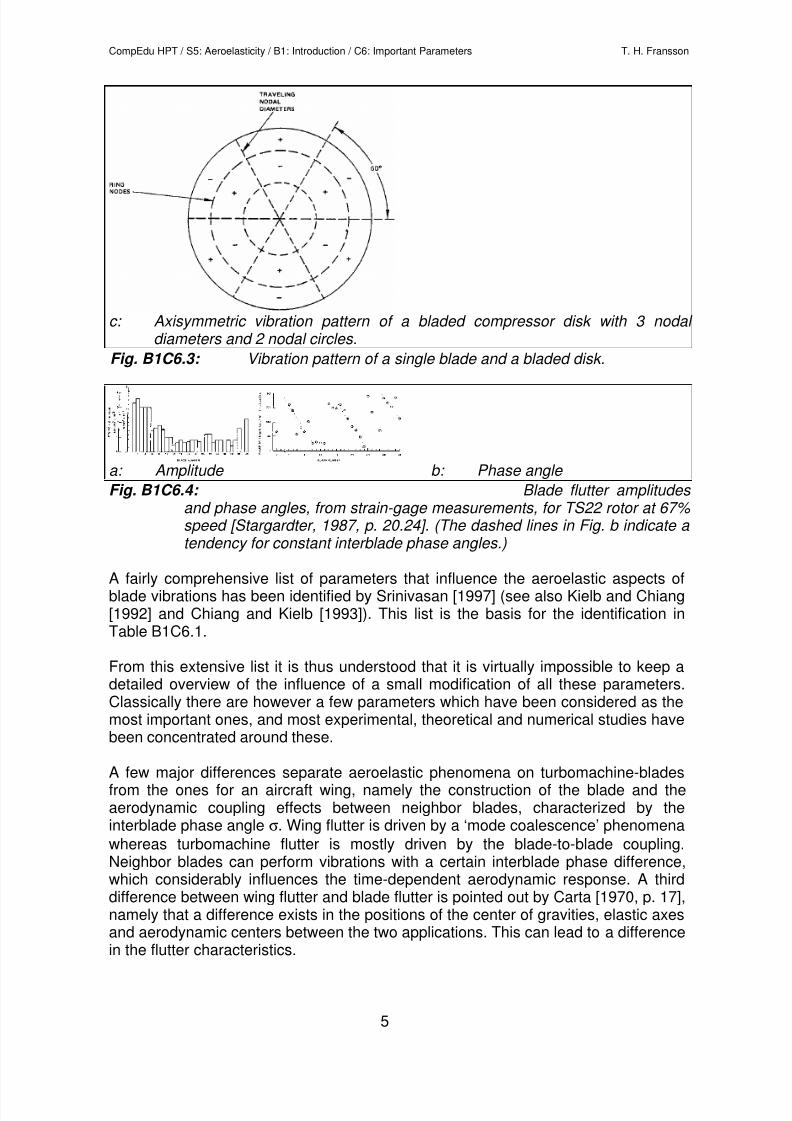
c: Axisymmetric vibration pattern of a bladed compressor disk with 3 nodal diameters and 2 nodal circles.
Fig. B1C6.3: Vibration pattern of a single blade and a bladed disk.
a: Amplitude b: Phase angle
Fig. B1C6.4: Blade flutter amplitudes and phase angles, from strain-gage measurements, for TS22 rotor at 67% speed [Stargardter, 1987, p. 20.24]. (The dashed lines in Fig. b indicate a tendency for constant interblade phase angles.)
A fairly comprehensive list of parameters that influence the aeroelastic aspects ofblade vibrations has been identified by Srinivasan [1997] (see also Kielb and Chiang[1992] and Chiang and Kielb [1993]). This list is the basis for the identification inTable B1C6.1.
From this extensive list it is thus understood that it is virtually impossible to keep adetailed overview of the influence of a small modification of all these parameters.Classically there are however a few parameters which have been considered as themost important ones, and most experimental, theoretical and numerical studies havebeen concentrated around these.
A few major differences separate aeroelastic phenomena on turbomachine-bladesfrom the ones for an aircraft wing, namely the construction of the blade and theaerodynamic coupling effects between neighbor blades, characterized by theinterblade phase angle σ. Wing flutter is driven by a ‘mode coalescence’ phenomena
whereas turbomachine flutter is mostly driven by the blade-to-blade coupling.Neighbor blades can perform vibrations with a certain interblade phase difference,which considerably influences the time-dependent aerodynamic response. A thirddifference between wing flutter and blade flutter is pointed out by Carta [1970, p. 17],namely that a difference exists in the positions of the center of gravities, elastic axesand aerodynamic centers between the two applications. This can lead to a difference
in the flutter characteristics.
8/13/2019 Media Lecture Notes S5B1C6
http://slidepdf.com/reader/full/media-lecture-notes-s5b1c6 6/17
CompEdu HPT / S5: Aeroelasticity / B1: Introduction / C6: Important Parameters T. H. Fransson
6
Blade characteristics stiffness mass ratio mode shape (frequency, position of torsion axis, phase angle between
bending and torsion, bending direction,…)
shroud location shroud angle blade attachment (fir tree, …) mechanical damping (in blade, at snubbers, under platform dampers, …) elastic coupling between blades structural mistuning (in frequency, damping, …) centrifugal softening/stiffening untwisting (because of centrifugal effects) steady stress (rotational tip speed, ..) Blade row geometry blade form (thickness/chord-ratio, …)
blade twist hub/tip-ratio aspect ratio stagger angle Blade row interaction number of blades in different blade rows circumferential position of stator (or rotor) blades in repeating stages axial gap between blade rows (forcing functions, reflections of perturbations,
...) distortion pattern (struts, combustion chambers, hot streaks, …) Flow conditions
inlet and outlet flow velocities incidence angle blade loading blade surface pressure distribution separation transition shock position shock motion incoming velocity defects incoming pressure defects aerodynamic mistuning (in blade shape, pitch, stagger, ….) absolute value of inlet and exit conditions (pressures, temperatures, …) General reduced frequency interblade phase angle
Table B1C6.1: Parameters that influence the aeroelastic aspects of blade vibrations (adapted from Srinivasan [1997])
8/13/2019 Media Lecture Notes S5B1C6
http://slidepdf.com/reader/full/media-lecture-notes-s5b1c6 7/17
CompEdu HPT / S5: Aeroelasticity / B1: Introduction / C6: Important Parameters T. H. Fransson
7
Blade characteristics
Turbomachine blades are usually made out of solid metal, contrary to airplane wings,which usually consists of empty space and relative lightweight metal. Theturbomachine blade is thus much stiffer than the airplane wing. The mass ratio
(mblade /mfluid, Fig. B1C6.5) of blade/fluid is thus also considerably larger and the time-dependent aerodynamic forces are generally not large enough to significantly alterthe natural mode shapes of the system at the rotational speed of interest. Self-excitedvibrations will thus mainly not be of the merging (or ‘coalescence’) mode type.
Fig. B1C6.5: Illustration of mass ratio
The mode shape of the bladed disk assembly (Figs. B1C6.2, B1C6.3) plays asignificant role for the aeroelastic behavior. The blade vibration natural frequency isthe first parameter to consider (although this is mostly related to the flow velocity to
form the so-called ‘reduced frequency’ [explained later in this section]). The higherthe frequency, the less likely is the system to enter into self-excited vibrations. This isillustrated in Fig. B1C6.1 (reduced frequency is the inverse of reduced velocity),where it is noted that, at constant incidence angle, the flutter region is extended withincreasing reduced velocity.
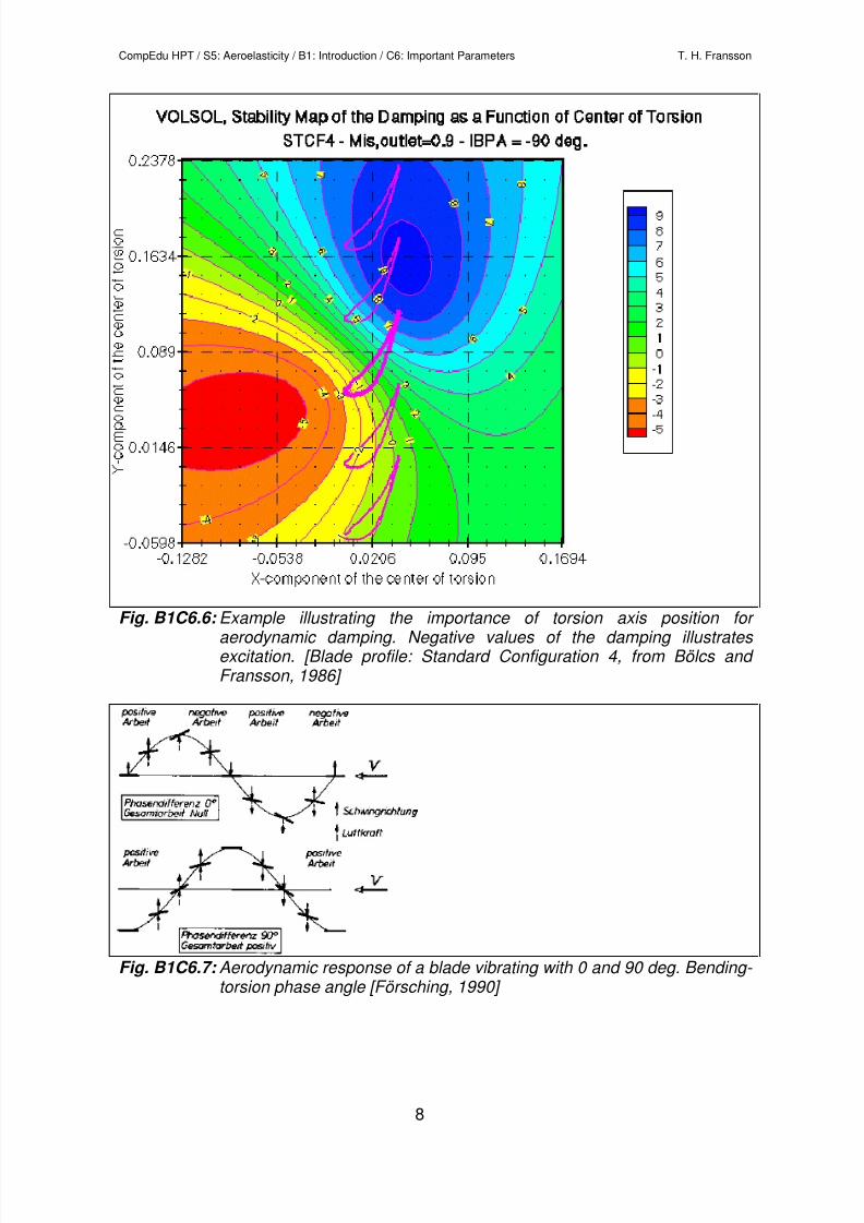
The position of the torsional axis is (as known already from airplane aeroelastictheory) extremely important. In Fig. B1C6.6 this is illustrated in a specific way, asproposed by Panovsky and Kielb [1998]. Each center of torsion position of thereference blade (thicker blade profile) gives a different aerodynamic damping. Theareas with positive aerodynamic damping indicate that a torsion axis (of the referenceblade) situated in this region gives a damped blade vibration. If the torsion axis of thereference blade is located in the area with negative aerodynamic work the bladevibration is excited. It is noted that certain regions have high gradients, whereas thegradients are lower at other places. From the design perspective, it would bebeneficial not to place the torsional axis in a region where the gradients are large,especially if the damping is close to changing sign in the same region.
8/13/2019 Media Lecture Notes S5B1C6
http://slidepdf.com/reader/full/media-lecture-notes-s5b1c6 8/17
CompEdu HPT / S5: Aeroelasticity / B1: Introduction / C6: Important Parameters T. H. Fransson
8
Fig. B1C6.6: Example illustrating the importance of torsion axis position for aerodynamic damping. Negative values of the damping illustrates excitation. [Blade profile: Standard Configuration 4, from Bölcs and Fransson, 1986]
Fig. B1C6.7: Aerodynamic response of a blade vibrating with 0 and 90 deg. Bending- torsion phase angle [Försching, 1990]
8/13/2019 Media Lecture Notes S5B1C6
http://slidepdf.com/reader/full/media-lecture-notes-s5b1c6 9/17
CompEdu HPT / S5: Aeroelasticity / B1: Introduction / C6: Important Parameters T. H. Fransson
9
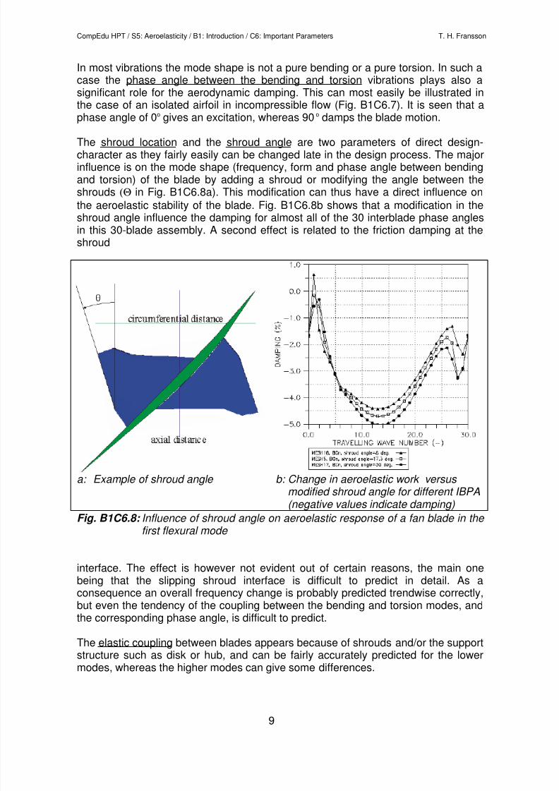
In most vibrations the mode shape is not a pure bending or a pure torsion. In such acase the phase angle between the bending and torsion vibrations plays also asignificant role for the aerodynamic damping. This can most easily be illustrated inthe case of an isolated airfoil in incompressible flow (Fig. B1C6.7). It is seen that aphase angle of 0o gives an excitation, whereas 90 o damps the blade motion.
The shroud location and the shroud angle are two parameters of direct design-character as they fairly easily can be changed late in the design process. The majorinfluence is on the mode shape (frequency, form and phase angle between bendingand torsion) of the blade by adding a shroud or modifying the angle between theshrouds (Θ in Fig. B1C6.8a). This modification can thus have a direct influence on
the aeroelastic stability of the blade. Fig. B1C6.8b shows that a modification in theshroud angle influence the damping for almost all of the 30 interblade phase anglesin this 30-blade assembly. A second effect is related to the friction damping at theshroud
a: Example of shroud angle b: Change in aeroelastic work versus modified shroud angle for different IBPA (negative values indicate damping)
Fig. B1C6.8: Influence of shroud angle on aeroelastic response of a fan blade in the
first flexural mode
interface. The effect is however not evident out of certain reasons, the main onebeing that the slipping shroud interface is difficult to predict in detail. As aconsequence an overall frequency change is probably predicted trendwise correctly,but even the tendency of the coupling between the bending and torsion modes, andthe corresponding phase angle, is difficult to predict.
The elastic coupling between blades appears because of shrouds and/or the supportstructure such as disk or hub, and can be fairly accurately predicted for the lower
modes, whereas the higher modes can give some differences.
8/13/2019 Media Lecture Notes S5B1C6
http://slidepdf.com/reader/full/media-lecture-notes-s5b1c6 10/17
CompEdu HPT / S5: Aeroelasticity / B1: Introduction / C6: Important Parameters T. H. Fransson
10
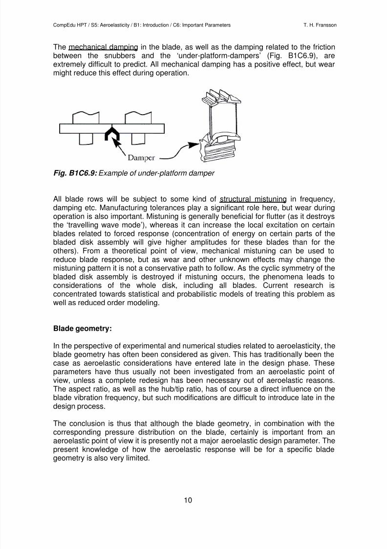
The mechanical damping in the blade, as well as the damping related to the frictionbetween the snubbers and the ‘under-platform-dampers’ (Fig. B1C6.9), areextremely difficult to predict. All mechanical damping has a positive effect, but wearmight reduce this effect during operation.
Fig. B1C6.9: Example of under-platform damper
All blade rows will be subject to some kind of structural mistuning in frequency,damping etc. Manufacturing tolerances play a significant role here, but wear duringoperation is also important. Mistuning is generally beneficial for flutter (as it destroysthe ‘travelling wave mode’), whereas it can increase the local excitation on certainblades related to forced response (concentration of energy on certain parts of thebladed disk assembly will give higher amplitudes for these blades than for theothers). From a theoretical point of view, mechanical mistuning can be used toreduce blade response, but as wear and other unknown effects may change themistuning pattern it is not a conservative path to follow. As the cyclic symmetry of the
bladed disk assembly is destroyed if mistuning occurs, the phenomena leads toconsiderations of the whole disk, including all blades. Current research isconcentrated towards statistical and probabilistic models of treating this problem aswell as reduced order modeling.
Blade geometry:
In the perspective of experimental and numerical studies related to aeroelasticity, theblade geometry has often been considered as given. This has traditionally been thecase as aeroelastic considerations have entered late in the design phase. These
parameters have thus usually not been investigated from an aeroelastic point ofview, unless a complete redesign has been necessary out of aeroelastic reasons.The aspect ratio, as well as the hub/tip ratio, has of course a direct influence on theblade vibration frequency, but such modifications are difficult to introduce late in thedesign process.
The conclusion is thus that although the blade geometry, in combination with thecorresponding pressure distribution on the blade, certainly is important from anaeroelastic point of view it is presently not a major aeroelastic design parameter. Thepresent knowledge of how the aeroelastic response will be for a specific bladegeometry is also very limited.
8/13/2019 Media Lecture Notes S5B1C6
http://slidepdf.com/reader/full/media-lecture-notes-s5b1c6 11/17
CompEdu HPT / S5: Aeroelasticity / B1: Introduction / C6: Important Parameters T. H. Fransson
11
Blade row interaction:
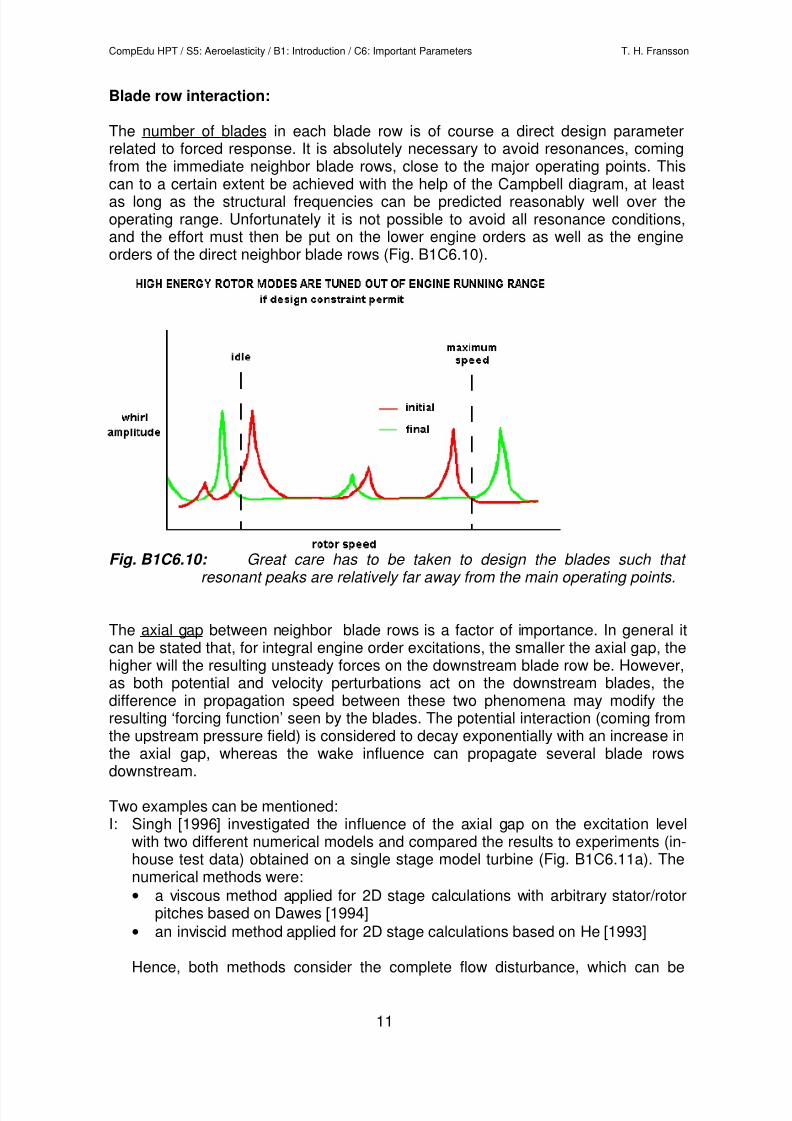
The number of blades in each blade row is of course a direct design parameterrelated to forced response. It is absolutely necessary to avoid resonances, comingfrom the immediate neighbor blade rows, close to the major operating points. This
can to a certain extent be achieved with the help of the Campbell diagram, at leastas long as the structural frequencies can be predicted reasonably well over theoperating range. Unfortunately it is not possible to avoid all resonance conditions,and the effort must then be put on the lower engine orders as well as the engineorders of the direct neighbor blade rows (Fig. B1C6.10).
Fig. B1C6.10: Great care has to be taken to design the blades such that resonant peaks are relatively far away from the main operating points.
The axial gap between neighbor blade rows is a factor of importance. In general itcan be stated that, for integral engine order excitations, the smaller the axial gap, thehigher will the resulting unsteady forces on the downstream blade row be. However,as both potential and velocity perturbations act on the downstream blades, thedifference in propagation speed between these two phenomena may modify theresulting ‘forcing function’ seen by the blades. The potential interaction (coming fromthe upstream pressure field) is considered to decay exponentially with an increase in
the axial gap, whereas the wake influence can propagate several blade rowsdownstream.
Two examples can be mentioned: I: Singh [1996] investigated the influence of the axial gap on the excitation level
with two different numerical models and compared the results to experiments (in-house test data) obtained on a single stage model turbine (Fig. B1C6.11a). Thenumerical methods were:
• a viscous method applied for 2D stage calculations with arbitrary stator/rotorpitches based on Dawes [1994]
• an inviscid method applied for 2D stage calculations based on He [1993]
Hence, both methods consider the complete flow disturbance, which can be
8/13/2019 Media Lecture Notes S5B1C6
http://slidepdf.com/reader/full/media-lecture-notes-s5b1c6 12/17
CompEdu HPT / S5: Aeroelasticity / B1: Introduction / C6: Important Parameters T. H. Fransson
12
modeled with either method. Of course with the inviscid method only a numericalwake can contribute to the flow disturbance. The exponential decrease for smallgaps were seen in the experimental results (Fig. B1C6.11a).
Error! Not a valid filename.
Fig. B1C6.11a: Variation of 1st
harmonic of unsteady blade force on the rotor blade root section in a turbine stage with axial gap, test vs.calculations [Singh, 1996]
II: Korakianitis [1992a,b] presented an interesting numerical study of the influence ofthe axial gap on the excitation level of the blades in a turbine stage of a gasturbine (Fig. B1C6.11b). The numerical method (UNSFLO [Giles, 1991]) wasused to calculate the 2D inviscid, compressible unsteady flow in the turbine rotorpassage. Separate calculations were performed for:a) only regarding a wake
b) regarding a potential flow disturbancec) regarding both a potential and a wake disturbance
These disturbances were prescribed at the inlet boundary of the rotor bladepassage. The prescribed wake amplitude and wake width were adapted to thespecified axial gap in order to take into account wake diffusion, which is notmodeled by the numerical method. The amplitude of the potential effect is keptthe same for all axial gaps, because the decay of the potential disturbance withaxial gap is regarded in the code.
An interesting result of this study is that due to the different phase behavior of thewake and potential disturbances with axial gap the excitation forces are minimalfor a certain axial gap. Each excitation source regarded on its own the excitationscontinuously decrease with increasing axial gap. Thus this study confirms theconclusions based on earlier measurements that an optimum axial gap betweenstators and rotors exist.
Error! Not a valid filename.
inflow angle rotational speed of rotor
time avarage (divided by 10)1st harmonic 2 nd harmonic
Fig. B1C6.11b: Unsteady blade forces f x (axial direction) vs. axial gap: numerical blade force analysis of the forces on a turbine rotor blade due to a)periodic wake flow disturbance, b) periodic potential flow disturbance upstream, c) combined potential and wake disturbance, Korakianitis [1992a,b]
The blade row interaction has also a certain importance related to non-integralengine order excitations. During flutter the perturbations created by the blade
8/13/2019 Media Lecture Notes S5B1C6
http://slidepdf.com/reader/full/media-lecture-notes-s5b1c6 13/17
CompEdu HPT / S5: Aeroelasticity / B1: Introduction / C6: Important Parameters T. H. Fransson
13
amplitudes will propagate up- and downstream. The presence of the neighbor bladerows will modify the propagation in the axial gap and will introduce reflections at theinterfaces which probably will not correspond to the reflections appearing during acascade test or during a numerical calculation.
In the case that repeating stages (same number of nozzles or blades) are used, it ispossible to significantly modify the unsteady response on the downstream stator (orrotor) blades by ‘clocking’ the nozzle (or blade) rows in the circumferential direction.
Struts, burner cans and other obstacles in the flow, as well as non-uniform inlet flowto the first blade row will give excitations of a relatively low engine order. As theseexcitations often give large blade response, great care is taken to design such thatthese are outside of the principal operating range (Fig. B1C6.10).
Flow conditions
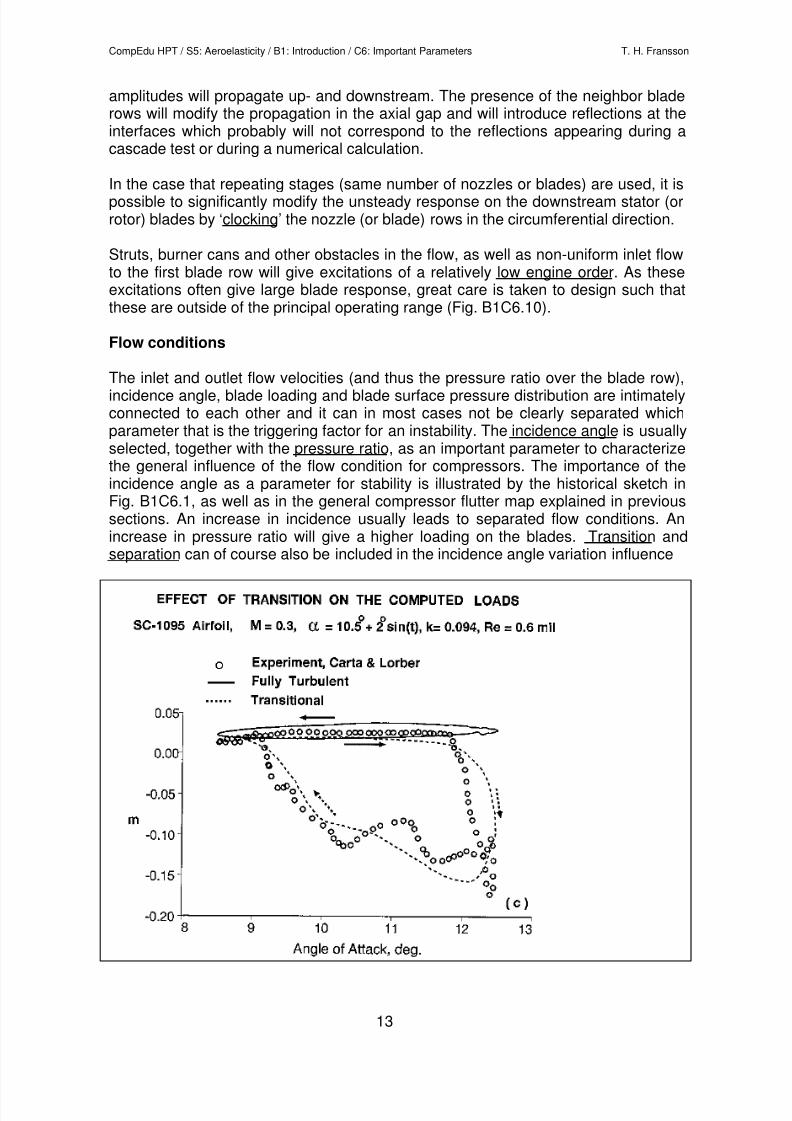
The inlet and outlet flow velocities (and thus the pressure ratio over the blade row),incidence angle, blade loading and blade surface pressure distribution are intimatelyconnected to each other and it can in most cases not be clearly separated whichparameter that is the triggering factor for an instability. The incidence angle is usuallyselected, together with the pressure ratio, as an important parameter to characterizethe general influence of the flow condition for compressors. The importance of theincidence angle as a parameter for stability is illustrated by the historical sketch inFig. B1C6.1, as well as in the general compressor flutter map explained in previoussections. An increase in incidence usually leads to separated flow conditions. Anincrease in pressure ratio will give a higher loading on the blades. Transition andseparation can of course also be included in the incidence angle variation influence
8/13/2019 Media Lecture Notes S5B1C6
http://slidepdf.com/reader/full/media-lecture-notes-s5b1c6 14/17
CompEdu HPT / S5: Aeroelasticity / B1: Introduction / C6: Important Parameters T. H. Fransson
14
Fig. B1C6.12: Comparison of fully turbulent and transitional computations with experimental data for an isolated airfoil at high incidence [Platzer and Ekaterinaris, 1995, Fig. 2c]
from a broad perspective, but detailed information about the importance of smallchanges in these parameters is not available in the literature today. One studyrelated to the eventual importance of a moving transition zone has been presentedby Platzer and Ekaterinaris [1995] (Fig. B1C6.12), in which numerical calculations onan isolated airfoil indicate that a fully turbulent calculation give results directlyopposed to experimental evidence related to aerodynamic damping for dynamic stall,whereas a calculation including a moving transition give a trendwise agreement withthe experimental data.
The shock position has a definite importance for the aeroelastic damping of a blade(as indicated in the compressor map in previous chapters), as well as for the blade
surface unsteady pressure load related to forced response. This influence canhowever be stabilizing or destabilizing, depending on other factors (for example theinterblade phase angle). The extent of the shock motion can also be of importance,although most results indicate that linear analysis are adequate for moderngeometries and flow conditions. In a stator-rotor environment it can happen thatshock waves move through a complete blade row. It is also highly possible thatshockwaves from one blade row can travel up- or down-stream and interfere withthis blade row, be reflected back into the original blade row and so forth. This canthen introduce high aerodynamic forcing functions at frequencies different from therotor passing frequency, which may be a source of non-integral engine orderexcitation.
Under some circumstances the absolute value of inlet and exit conditions (pressuresand temperatures) can influence the aeroelastic response (the mass ratio, Fig.B1C6.5, is influenced). As the density increases with increasing pressure, an alreadystable situation becomes more stable. However, in an unstable situation where thetotal damping is positive (with positive mechanical and negative aerodynamicdamping), an increase in density may shift the stability margin, as quantified byJeffers and Meece [1975]. This absolute pressure and temperature level can haveother effects also. Lubomski [1980] reports on a flutter frequency shift of 3-4%, andJeffers and Meece [1975] indicate that the increased steady-state loading candeform the blade such that the corresponding change in the leading edge metalangle, the camber and the cascade stagger can give at least a partial shift instability.
Incoming velocity (wake interactions) and pressure (potential interaction) defects areof importance for forced response studies. The magnitude and phase of these aredirectly related to the flow conditions in the upstream blade row. As long as it is notpossible to calculate the flow separations, and thus the width of the wake, theprediction of the incoming disturbances must be made empirically.
Most blade rows must be considered to have a certain aerodynamic (as well as the
previously mentioned mechanical) mistuning (for example because of manufacturingtolerances in blade pitch, stagger angle, …), although it is likely that these effects areless severe than the mechanical mistuning. A major concern can however be in

8/13/2019 Media Lecture Notes S5B1C6
http://slidepdf.com/reader/full/media-lecture-notes-s5b1c6 15/17
CompEdu HPT / S5: Aeroelasticity / B1: Introduction / C6: Important Parameters T. H. Fransson
15
cases where a blade fails so that a significant low engine order excitation isintroduced into the system, but this falls rather into the category of forced responsethan in aerodynamic mistuning. Only limited research has till presently beenperformed in this field.
8/13/2019 Media Lecture Notes S5B1C6
http://slidepdf.com/reader/full/media-lecture-notes-s5b1c6 16/17
CompEdu HPT / S5: Aeroelasticity / B1: Introduction / C6: Important Parameters T. H. Fransson
16
General
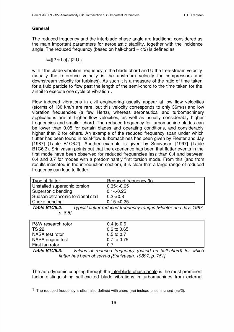
The reduced frequency and the interblade phase angle are traditional considered asthe main important parameters for aeroelastic stability, together with the incidenceangle. The reduced frequency (based on half-chord = c/2) is defined as
k={[2 π f c] / [2 U]}
with f the blade vibration frequency, c the blade chord and U the free-stream velocity(usually the reference velocity is the upstream velocity for compressors anddownstream velocity for turbines). As such it is a measure of the ratio of time takenfor a fluid particle to flow past the length of the semi-chord to the time taken for theairfoil to execute one cycle of vibration1.
Flow induced vibrations in civil engineering usually appear at low flow velocities(storms of 130 km/h are rare, but this velocity corresponds to only 36m/s) and low
vibration frequencies (a few Hertz), whereas aeronautical and turbomachineryapplications are at higher flow velocities, as well as usually considerably higherfrequencies and smaller chord. The reduced frequency for turbomachine blades canbe lower than 0.05 for certain blades and operating conditions, and considerablyhigher than 2 for others. An example of the reduced frequency span under whichflutter has been found in axial-flow turbomachines has been given by Fleeter and Jay[1987] (Table B1C6.2). Another example is given by Srinivasan [1997] (TableB1C6.3). Srinivasan points out that the experience has been that flutter events in thefirst mode have been observed for reduced frequencies less than 0.4 and between0.4 and 0.7 for modes with a predominantly first torsion mode. From this (and fromresults indicated in the introduction section), it is clear that a large range of reduced
frequency can lead to flutter.
Type of flutter Reduced frequency (k)Unstalled supersonic torsion 0.35->0.65Supersonic bending 0.1->0.25Subsonic/transonic torsional stall 0.2->0.8Choke bending 0.15->0.25
Table B1C6.2: Typical flutter reduced frequency ranges [Fleeter and Jay, 1987,p. 8.5]
P&W research rotor 0.4 to 0.6TS 22 0.6 to 0.65NASA test rotor 0.5 to 0.7NASA engine test 0.7 to 0.75First fan rotor 0.7
Table B1C6.3: Values of reduced frequency (based on half-chord) for which flutter has been observed [Srinivasan, 19897, p. 751]
The aerodynamic coupling through the interblade phase angle is the most prominentfactor distinguishing self-excited blade vibrations in turbomachines from external
1 The reduced frequency is often also defined with chord (=c) instead of semi-chord (=c/2).
8/13/2019 Media Lecture Notes S5B1C6
http://slidepdf.com/reader/full/media-lecture-notes-s5b1c6 17/17
CompEdu HPT / S5: Aeroelasticity / B1: Introduction / C6: Important Parameters T. H. Fransson
17
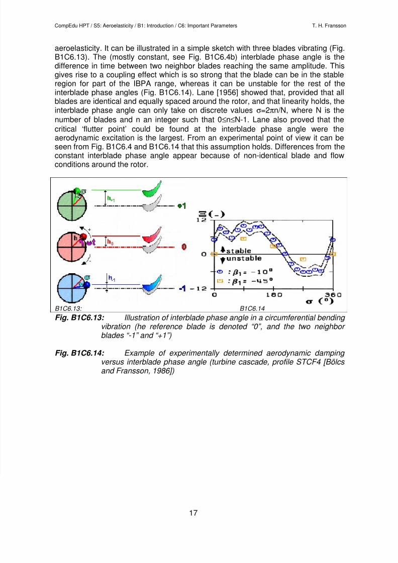
aeroelasticity. It can be illustrated in a simple sketch with three blades vibrating (Fig.B1C6.13). The (mostly constant, see Fig. B1C6.4b) interblade phase angle is thedifference in time between two neighbor blades reaching the same amplitude. Thisgives rise to a coupling effect which is so strong that the blade can be in the stableregion for part of the IBPA range, whereas it can be unstable for the rest of the
interblade phase angles (Fig. B1C6.14). Lane [1956] showed that, provided that allblades are identical and equally spaced around the rotor, and that linearity holds, theinterblade phase angle can only take on discrete values σ=2πn/N, where N is the
number of blades and n an integer such that 0≤n≤N-1. Lane also proved that the
critical ‘flutter point’ could be found at the interblade phase angle were theaerodynamic excitation is the largest. From an experimental point of view it can beseen from Fig. B1C6.4 and B1C6.14 that this assumption holds. Differences from theconstant interblade phase angle appear because of non-identical blade and flowconditions around the rotor.
B1C6.13: B1C6.14
Fig. B1C6.13: Illustration of interblade phase angle in a circumferential bending vibration (he reference blade is denoted “0”, and the two neighbor blades “-1” and “+1”)
Fig. B1C6.14: Example of experimentally determined aerodynamic damping versus interblade phase angle (turbine cascade, profile STCF4 [Bölcs and Fransson, 1986])