Embed Size (px)
Citation preview

IEEE 802.16.1mc-00/21r0
PRELIM
INARY S
UBMIT
TAL
Project IEEE 802.16 Broadband Wireless Access Working Group
Title Media Access Control Layer Proposal for the 802.16 Air Interface Specification
DateSubmitted
2000-07-07
Source Glen SaterMotorola Inc.8220 E. Roosevelt Street, M/D R1106 Scottsdale, AZ 85257
Ken StanwoodEnsemble Communications Inc.9890 Town Centre Dr.San Diego, CA 92121
Voice: 480-441-8893Fax: 480-675-2116E-mail: [email protected]
Voice: 858-404-6544Fax: 858-458-1401E-mail: [email protected]
Additional ContirbutionsArun Arunachalam, George StamatelosJeff FoersterScott Marin, Bill MyersLeland Langston, Wayne HunterPhil GuillemetteChet Shirali, Menashe ShaharKarl StambaughGeorge FishelRay SandersMoshe RanAndrew SundelinYonatan ManorBrian Petry, Mark VogelDr. James MollenauerCarl Eklund, Juha Pihlaja, Kari RintanenDoug GreyPaolo BaldoPaul KennardAndrea NascimbeneNaftali Chayat, Leonid Shousterman, Vladimir YanoverDr. Demosthenes KostasJay Klein
CompanyNortel NetworksAlcatelSpectraPoint Wireless, LLC.Crosspan, a Raytheon Telecommunications CompanySpaceBridge Networks CorporationVyyo Inc.Motorola, Inc.Communications Consulting ServicesCircuitPath Networks SystemsTelesciCOM, Ltd.iSKYOren Semiconductors3ComTechnical Strategy AssociatesNokiaLucent TechnologiesSiemensDigital MicrowaveEricssonBreezeCOM
Adaptive BroadbandEnsemble Communications
Re: 802.16.1 INVITATION TO CONTRIBUTE: Session #8, Document IEEE 802.16-00/13r1
Abstract This is a joint proposal that merges two contributions presented to the Working Group during Session #7 (documents IEEE 802.16.1mc-00/14 and IEEE 802.16.1mc-00/15). The process of combining the two documents was guided by the outline of agreements developed in Session #7.5, which amended the Call for Contributions for Session #8.
The proposed MAC provides connection-oriented links between the Base Station and CPEs. Each connection is associated with peer convergence sub-processes and service flows. Higher-layer infor-mation is tunneled through the MAC using the QoS provided by the serivce flows. In this manner, the MAC can be extended to support a wide variety of bearer transport and signaling mechanisms without modification to the core MAC services. The MAC fully supports the merged PHY layer as defined in 802.16.1pc-00/29r1.
Purpose To provide a detailed description of a proposed MAC layer specification for IEEE 802.16 WG.
Note: This is a preliminary submittal that will be updated during the IEEE 802.16.1 Working Group Session #8.
Notice This document has been prepared to assist IEEE 802.16. It is offered as a basis for discussion and is not binding on the contributing individual(s) or organization(s). The material in this document is sub-ject to change in form and content after further study. The contributor(s) reserve(s) the right to add, amend or withdraw material contained herein.

IEEE 802.16.1mc-00/21r0
ion tent
ple-
rd is ood
been
PRELIM
INARY S
UBMIT
TAL
Release The contributor grants a free, irrevocable license to the IEEE to incorporate text contained in this contribution, and any modifications thereof, in the creation of an IEEE Standards publication; to copyright in the IEEE’s name any IEEE Standards publication even though it may include portions of this contribution; and at the IEEE’s sole discretion to permit others to reproduce in whole or in part the resulting IEEE Standards publication. The contributor also acknowledges and accepts that this contribution may be made public by IEEE 802.16.
Portions of this document are reprinted with permission from Cable Television Laboratories, Inc.
IEEE Patent Policy
The contributor is familiar with the IEEE 802.16 Patent Policy and Procedures (Version 0.9) <http://ieee802.org/16/ipr/patents/policy.html>, including the statement “IEEE standards may include the known use of patent(s), including patent applications, if there is technical justification in the opinof the standards-developing committee and provided the IEEE receives assurance from the paholder that it will license applicants under reasonable terms and conditions for the purpose of immenting the standard.”Early disclosure to the Working Group of patent information that might be relevant to the standaessential to reduce the possibility for delays in the development process and increase the likelihthat the draft publication will be approved for publication. Please notify the Chair <mailto:[email protected]> as early as possible, in written or electronic form, of any patents (granted or under application) that may cover technology that is under consideration by or has approved by IEEE 802.16. The Chair will disclose this notification via the IEEE 802.16 web site<http://ieee802.org/16/ipr/patents/letters.html>.
2

IEEE 802.16.1mc-00/21r0
.... 51
...... 52.... 53..... 54.. 56...... 57....... 58.... 59..... 61.... 62..... 62.... 63.......... 65..... 67..... 67..... 70...... 71....
..... 75
..... 78
.......
PRELIM
INARY S
UBMIT
TAL
1. Overview.............................................................................................................................................. 7
1.1 Scope............................................................................................................................................ 71.2 Purpose......................................................................................................................................... 7
2. Normative References.......................................................................................................................... 9
3. Definitions ......................................................................................................................................... 11
4. Acronyms and abbreviations ............................................................................................................. 13
5. MAC Service Definition.................................................................................................................... 17
6. Media Access Control........................................................................................................................ 19
6.1 Connections and Service Flows................................................................................................. 196.1.1 Addressing and Connection Identifiers.......................................................................... 20
6.2 DOWNLINKMessage Formats ................................................................................................. 236.2.1 Convergence Sub-layer PDU Formats........................................................................... 276.2.2 MAC Management Messages........................................................................................ 276.2.3 Downlink MAP (DS-MAP) Message ............................................................................ 346.2.4 Uplink MAP Message.................................................................................................... 376.2.5 Ranging Request (RNG-REQ) Message........................................................................ 406.2.6 Ranging Response (RNG-RSP) Message ...................................................................... 416.2.7 Registration Request (REG-REQ) Message .................................................................. 466.2.8 Registration Response (REG-RSP) Message ................................................................ 476.2.9 Registration Acknowledge (REG-ACK) Message ........................................................ 496.2.10 Privacy Key Management — Request (PKM-REQ) Message ..................................6.2.11 Privacy Key Management — Response (PKM-RSP) Message...............................6.2.12 Dynamic Service Addition — Request (DSA-REQ) Message..................................6.2.13 Dynamic Service Addition — Response (DSA-RSP) Message ...............................6.2.14 Dynamic Service Addition — Acknowledge (DSA-ACK) Message..........................6.2.15 Dynamic Service Change — Request (DSC-REQ) Message..................................6.2.16 Dynamic Service Change — Response (DSC-RSP) Message ...............................6.2.17 Dynamic Service Change — Acknowledge (DSC-ACK) Message ..........................6.2.18 Dynamic Service Deletion — Request (DSD-REQ) Message .................................6.2.19 Multicast Polling Assignment Request (MCA-REQ) Message.................................6.2.20 Multicast Polling Assignment Response (MCA-RSP) Message ..............................6.2.21 Downlink Modulation Change Request (DMC-REQ) Message................................
6.3 Framing and Scheduling Intervals ........................................................................................ 656.3.1 PHY Burst Mode Support.........................................................................................6.3.2 PHY Continuous Mode Support ...............................................................................6.3.3 Downlink Burst Subframe Structure.........................................................................6.3.4 Uplink Burst Subframe Structure .............................................................................6.3.5 Continuous Downstream and Upstream Structure...................................................6.3.6 Upstream Map............................................................................................................ 716.3.7 Requests ......................................................................................................................... 746.3.8 MAP Relevance and Synchronization ......................................................................
6.4 Contention Resolution ............................................................................................................... 766.4.1 Transmit Opportunities .............................................................................................
6.5 Fragmentation ............................................................................................................................ 786.5.1 Policy and Rules ........................................................................................................ 786.5.2 Error Conditions ......................................................................................................... 78
6.6 Upstream Service....................................................................................................................... 78
3

IEEE 802.16.1mc-00/21r0
PRELIM
INARY S
UBMIT
TAL
6.6.1 Unsolicited Grant Service.............................................................................................. 796.6.2 Real-Time Polling Service............................................................................................. 796.6.3 Unsolicited Grant Service with Activity Detection ....................................................... 796.6.4 Non-Real-Time Polling Service..................................................................................... 806.6.5 Best Effort Service......................................................................................................... 80
6.7 Bandwidth Allocation and Request Mechanisms ...................................................................... 816.7.1 Polling............................................................................................................................ 816.7.2 Poll-Me Bit .................................................................................................................... 856.7.3 Piggy-Back and Bandwidth Requests............................................................................ 86
6.8 Network Entry and Initialization ............................................................................................... 876.8.1 Scanning and Synchronization to Downstream ............................................................. 886.8.2 Obtain Downstream Parameters .................................................................................... 896.8.3 Obtain Upstream Parameters ......................................................................................... 896.8.4 message Flows During Scanning and Upstream Parameter Acquisition....................... 916.8.5 Initial Ranging and Automatic Adjustments ................................................................. 926.8.6 Ranging Parameter Adjustment ..................................................................................... 986.8.7 Initial Connection Establishment................................................................................... 986.8.8 Transfer Operational Parameters ................................................................................... 98
6.9 Ranging.................................................................................................................................... 1066.10 Quality of Service .................................................................................................................... 111
6.10.1 Theory of Operation..................................................................................................... 1116.10.2 Service Flows............................................................................................................... 1116.10.3 Object Model (FIX THIS SECTION) ......................................................................... 1146.10.4 Service Classes ............................................................................................................ 1156.10.5 Authorization ............................................................................................................... 1166.10.6 Types of Service Flows................................................................................................ 1176.10.7 General Operation........................................................................................................ 1196.10.8 Dynamic Service.......................................................................................................... 1216.10.9 Dynamic Service Addition........................................................................................... 1306.10.10Dynamic Service Change............................................................................................. 1426.10.11Connection Release...................................................................................................... 1536.10.12Dynamic Service Deletion State Transition Diagrams ................................................ 155
6.11 Parameters and Constants ........................................................................................................ 1636.12 Encodings for Configuration and MAC-Layer Messaging...................................................... 165
6.12.1 Configuration File and Registration Settings............................................................... 1656.12.2 Configuration-File-Specific Settings ........................................................................... 1696.12.3 Registration-Request/Response-Specific Encodings................................................... 1716.12.4 Dynamic-Service-Message-Specific Encodings.......................................................... 1736.12.5 Quality-of-Service-Related Encodings ........................................................................ 1746.12.8 Privacy Configuration Settings Option........................................................................ 1856.12.9 Confirmation Code ...................................................................................................... 185
7. Authentication and Privacy.............................................................................................................. 187
8. Transmission Convergence Sublayer............................................................................................... 189
4

IEEE 802.16.1mc-00/21r0
PRELIM
INARY S
UBMIT
TAL
5

IEEE 802.16.1mc-00/21r0
PRELIM
INARY S
UBMIT
TAL
6

PRELIM
INARY S
UBMIT
TAL
1. Overview
1.1 Scope
The scope of this standard is to develop a medium access control (MAC) and physical layer (PHY) specifi-cation for wireless connectivity for broadband wireless access systems.
1.2 Purpose
<TBD>.
7

IEEE 802.16.1mc-00/21r0
PRELIM
INARY S
UBMIT
TAL
8

IEEE 802.16.1mc-00/21r0
PRELIM
INARY S
UBMIT
TAL
2. Normative References
This standard shall be used in conjunction with the following publications. [If the working group wishes toreference the most current edition of the standard, they should include the following line: When the follow-ing standards are superseded by an approved revision, the revision shall apply.]
Insert first reference here. For subsequent references, hit return so that the paragraph format References isused for each entry.
9

IEEE 802.16.1mc-00/21r0
PRELIM
INARY S
UBMIT
TAL
10

IEEE 802.16.1mc-00/21r0
PRELIM
INARY S
UBMIT
TAL
3. Definitions
3.1 Base Station (BS):
3.2 Burst Profile:
3.3 Connection:
3.4 Connection Identifier (CID):
3.5 Customer Premises Equipment (CPE):
3.6 Downstream/Downlink:
3.7 Frame:
3.8 Information Element (IE):
3.9 Interval Usage Code (IUC):
3.10 Grant Per Connection:
3.11 Grant Per Terminal:
3.12 MAP:
3.13 Mini-slot:
3.14 Physical-Slot (PS):
3.15 Scheduling Interval:
3.16 Service Flow:
3.17 Service Flow Class:
3.18 Service Flow Name:
3.19 Upstream/Uplink:
11

IEEE 802.16.1mc-00/21r0
PRELIM
INARY S
UBMIT
TAL
12

IEEE 802.16.1mc-00/21r0
PRELIM
INARY S
UBMIT
TAL
4. Acronyms and abbreviations
ATDD Adaptive Time Division DuplexingBR Bandwidth RequestBS Base StationCG Continuous GrantCID Connection IdentifierCPE Customer Premises EquipmentCS Convergence SubprocessCSI Convergence Subprocess IndicatorCTG CPE Transition GapDAMA Demand Assign Multiple AccessDES Data Encryption StandardDL Down LinkDSA Dynamic Service AdditionDSC Dynamic Service ChangeDSD Dynamic Service DeletionEC Encryption ControlEKS Encryption Key SequenceFC Fragment ControlFDD Frequency Division DuplexFSN Fragment Sequence NumberGM Grant ManagementGPC Grant Per ConnectionGPT Grant Per TerminalHCS Header Check SequenceH-FDD Half-duplex FDDHL-MAA High Level Media Access ArbitrationHT Header TypeIE Information ElementIUC Interval Usage CodeLL-MAA Low Level Media Access ArbitrationMAC Medium Access ControlMIC Message Integrity CheckMTG Modulation Transition GapPCD Physical Channel DescriptorPBR Piggy-Back RequestPDU Protocol Data UnitPHY Physical layerPI PHY Information elementPKM Privacy Key ManagementPM Poll Me bitPS Physical SlotQoS Quality of ServiceRS Reed-SolomonSAP Service Access PointSI Slip IndicatorSDU Service Data UnitTC Transmission ConvergenceTDD Time Division DuplexTDM Time Division MultiplexTDMA Time Division Multiple AccessTDU TC Data UnitTLV Type-Length-Value
13

IEEE 802.16.1mc-00/21r0
PRELIM
INARY S
UBMIT
TAL
TRGT Tx/Rx Transmission GapUGS Unsolicited Grant ServiceUGS-AD Unsolicited Grant Service with Activity DetectionUL Up Link
14

IEEE 802.16.1mc-00/21r0
PRELIM
INARY S
UBMIT
TAL
15

IEEE 802.16.1mc-00/21r0
PRELIM
INARY S
UBMIT
TAL
16

IEEE 802.16.1mc-00/21r0
PRELIM
INARY S
UBMIT
TAL
5. MAC Service Definition
<TBD>.
17

IEEE 802.16.1mc-00/21r0
PRELIM
INARY S
UBMIT
TAL
18

IEEE 802.16.1mc-00/21r0
PRELIM
INARY S
UBMIT
TAL
6. Media Access Control
In a network that utilizes a shared medium, there must be a mechanism to provide an efficient way to sharethe medium. A two-way point-to-multipoint wireless network is a good example of a shared medium: herethe medium is the space through which the radio waves propagate.
The downlink, from the base station to the user operates on a point-to-multipoint basis. The 802.16.1 wire-less link operates with a central base station and a sectorized antenna which is capable of handling multipleindependent sectors simultaneously. Within a given frequency channel and antenna sector, all stationsreceive the same transmission. The base station is the only transmitter operating in this direction, hence itcan transmit without having to coordinate with other stations, except for the overall time-division duplexingthat divides time into upstream and downstream transmission periods. It broadcasts to all stations in the sec-tor (and frequency); stations check the address in the received messages and retain only those addressed tothem.
However, the user stations share the upstream period on a demand basis. Depending on the class of serviceutilized, the CPE may be issued continuing rights to transmit, or the right to transmit may be granted by thebase station after receipt of a request from the user.
In addition to individually-addressed messages, messages may also be sent to multicast groups (controlmessages and video distribution are examples of multicast applications) as well as broadcast to all stations.
Within each sector, users must adhere to a transmission protocol which minimizes contention between usersand enables the service to be tailored to the delay and bandwidth requirements of each user application.
This is accomplished through five different types of upstream scheduling mechanism, which are imple-mented using unsolicitied bandwidth grants, polling, and contention procedures. Mechanisms are defined inthe protocol to allow vendors to optimize system performance using different combinations of these band-width allocation techniques while maintaining consistent inter-operability definitions. For example, conten-tion can be used to avoid the individual polling of CPEs which have been inactive for a long period of time.
The use of polling simplifies the access operation and guarantees that applications receive service on a deter-ministic basis if it is required. In general, data applications are delay tolerant, but real-time applications likevoice and video require service on a more uniform basis, and sometimes on a very tightly-controlled sched-ule.
6.1 Connections and Service Flows
The MAC is connection-oriented. For the purposes of mapping to services on CPEs and associating varyinglevels of QoS, all data communications are in the context of a connection. These connections are provi-sioned when a CPE is installed in the system, and set up over the air at CPE registration to provide a refer-ence against which to request bandwidth. Additionally, new connections may be established whencustomer’s service needs change. A connection defines both the mapping between peer convergence pro-cesses that utilize the MAC and a Service Flow. The Service Flow defines the QoS parameters for the PDUsthat are exchanged on the connection.
The concept of a Service Flow on a Connection is central to the operation of the MAC protocol. ServiceFlows provide a mechanism for upstream and downstream Quality of Service management. In particular,they are integral to the bandwidth allocation process. A CPE requests upstream bandwidth on a per-connec-tion basis (implicitly identifying the Service Flow). Bandwidth is granted by the BS either as an aggregate ofall grants for a CPE (within a scheduling interval) or on a connection basis.
19

IEEE 802.16.1mc-00/21r0
PRELIM
INARY S
UBMIT
TAL
Once connections are established they must be maintained. The maintenance requirements vary dependingupon the type of service connected. For example, unchannelized T1 services require virtually no connectionmaintenance since they have a constant bandwidth allocated every frame. Channelized T1 services requiresome maintenance due to the dynamic (but relatively slowly changing) bandwidth requirements if com-pressed, coupled with the requirement that full bandwidth be available on demand. IP services may requirea substantial amount of ongoing maintenance due to their bursty nature and due to the high possibility offragmentation across frames. As with connection establishment, modifiable connections may require main-tenance due to stimulus from either the CPE or the network side of the connection.
Finally, connections may be terminated. This generally occurs only when a customer’s service contractchanges. The termination of a connection is stimulated by the BS or CPE.
All three of these connection management functions are supported throught the use of static configurationand dynamic addition, modification, and deletion of connections.
6.1.1 Addressing and Connection Identifiers
Each CPE shall maintain a 64-bit EUI for globally unique addressing purposes. This address uniquelydefines the CPE from within the set of all possible vendors and equipment types. This address is used duringthe registration process to establish the appropriate connections for a CPE. It is also used as part of theauthentication process by which the BS and CPE each verify the identity of each other.
Connections are identified by a 16-bit Connection Identifier. Every CPE must establish at least two connec-tions in each direction (upstream and downstream) to enable communication with the BS. The Basic Con-nection IDs, assigned to a CPE at registration, are used by the BS MAC and the CPE MAC to exchangeMAC control messages, provisioning and management information.
For bearer services, the higher layers of the BS set up connections based upon the provisioning informationdistributed to the base station. The registration of a CPE, or the modification of the services contracted at aCPE, stimulates the higher layers of the BS to initiate the setup of the connections.
The connection ID can be considered a connection identifier even for nominally connectionless traffic likeIP, since it serves as a pointer to destination and context information. The use of a 16-bit connection ID per-mits a total of 64K connections within the sector.
Requests for transmission are based on these connection IDs, since the allowable bandwidth may differ fordifferent connections, even within the same service type. For example, a CPE unit serving multiple tenantsin an office building would make requests on behalf of all of them, though the contractual service limits andother connection parameters may be different for each of them.
Many higher-layer sessions may operate over the same wireless connection ID. For example, many userswithin a company may be communicating with TCP/IP to different destinations, but since they all operatewithin the same overall service parameters, all of their traffic is pooled for request/grant purposes. Since theoriginal LAN source and destination addresses are encapsulated in the payload portion of the transmission,there is no problem in identifying different user sessions.
The type of service is implicit in the connection ID; it is accessed by a lookup indexed by the connection ID.
There are several CIDs defined in Table 1 that having specific meaning. These identifiers shall not be usedfor any other purposes.
20

IEEE 802.16.1mc-00/21r0
PRELIM
INARY S
UBMIT
TAL
Table 1—Connection Identifiers
Connection Identifier Value Description
Initial Ranging 0x0000 Used by a CPE during initial ranging as part of network entry process.
Temporary Registration 0..m
Basic CIDs m..n
Transport CIDs n..0xFDFF
Priority Request CIDs 0xFEXX Request IE UsageIf 0x01 bit is set, priority zero can requestIf 0x02 bit is set, priority one can requestIf 0x04 bit is set, priority two can requestIf 0x08 bit is set, priority three can requestIf 0x10 bit is set, priority four can requestIf 0x20 bit is set, priority five can requestIf 0x40 bit is set, priority six can requestIf 0x80 bit is set, priority seven can request
Multicast Polling CIDs 0xFF00..0xFFFE A CPE may be included in one or more multicast groups for the purposes of obtaining bandwidth via polling. These connections have no associated Service Flow.
Broadcast CID 0xFFFF Used for broadcast information that is transmitted on a downlink to all CPE.
21

IEEE 802.16.1mc-00/21r0
PRELIM
INARY S
UBMIT
TAL
22

IEEE 802.16.1mc-00/21r0
PRELIM
INARY S
UBMIT
TAL
6.2 DOWNLINKMessage Formats
Three MAC header formats are defined. The first two are generic headers that precede each MAC Message,including both management and convergence sub-layer data. The third format is used to request additionalbandwidth. The single bit Header Type (HT) field distinguishes the generic and bandwidth request headerformats. The HT field shall be set to 0 for generic headers. The HT field shall be set to 1 for a bandwidthrequest header.
The format shown in Figure 2 shall be used for all PDUs transmitted by the CPE to the BS in the uplinkdirection. For downlink transmissions, the format shown in Figure 2 shall be used.
HCS
Figure 1—Generic MAC Header Format (Uplink)
LengthEC EKS
Connection Identifier
GMHT FC FSN
Piggy-Back Request
Grants Per IntervalSI
SI PMUnsolicited Grant Service
Unsolicited Grant Servicewith Activity Detection
All others
Grant Management
CLI=0
Bit 0 8 15
23

IEEE 802.16.1mc-00/21r0
PRELIM
INARY S
UBMIT
TAL
These two generic header formats are equivalent with the exception of the Grant Mangament field, which isonly present in uplink transmissions.
The Grant Management field is one byte in length and is used by the CPE to convey bandwidth managementneeds to the BS. This field is encoded differently based upon the type of connection (as given by the Con-nection ID). The use of this field is defined in Section 6.7.
The third header is a special format used by a CPE to request additional bandwidth. This header shall alwaysbe transmitted without a PDU. The format of the Bandwidth Request Header is given in Figure 3.
The Bandwidth Request Header is used by a CPE to request uplink bandwidth. A Bandwidth RequestHeader shall not have an associated payload:
a) The length of the header shall always be 7 bytes,b) The EC field shall be set to 1, indicating no encryption,c) The CID shall indicate the Service Flow for which uplink bandwidth is requested,d) The Bandwidth Request (BR) field shall indicate the number of mini-slots requested.
A CPE receiving a Bandwidth Request Header on the downlink shall discard the PDU.
HCS
Figure 2—Generic MAC Header Format (Downlink)
LengthEC EKS
Connection Identifier
HT FC FSNCSI=0
Bit 0 8 15
Figure 3—Bandwidth Request Header Format
Length (=7)
CID
HT BR
1
HCS
=1
0000
Bit 0 8 15
24

IEEE 802.16.1mc-00/21r0
PRELIM
INARY S
UBMIT
TAL
The various fields of the header formats are defined in Table 2. Every header is encoded starting with the ECand EKS fields. The coding of these fields is such that the first byte of a MAC header shall never have thevalue of 0xFX. This prevents false detection on the stuff byte used in the Transmission Convergence Sub-layer.
Table 2—MAC Header Fields
Name Length(bits) Description
BR 15 Bandwidth Request
The number of bytes of uplink bandwidth requested by the CPE. The bandwidth request is for the CID. The request shall not include any PHY layer overhead
CID 16 Connection Identifier
CSI 1 Convergence Sub-layer Indication
This bit is allocated to a convergence layer process for signaling between equivalent peers.
EC 1 Encryption Control
1 = Payload is not encrypted0 = Payload is encrypted
25

IEEE 802.16.1mc-00/21r0
PRELIM
INARY S
UBMIT
TAL
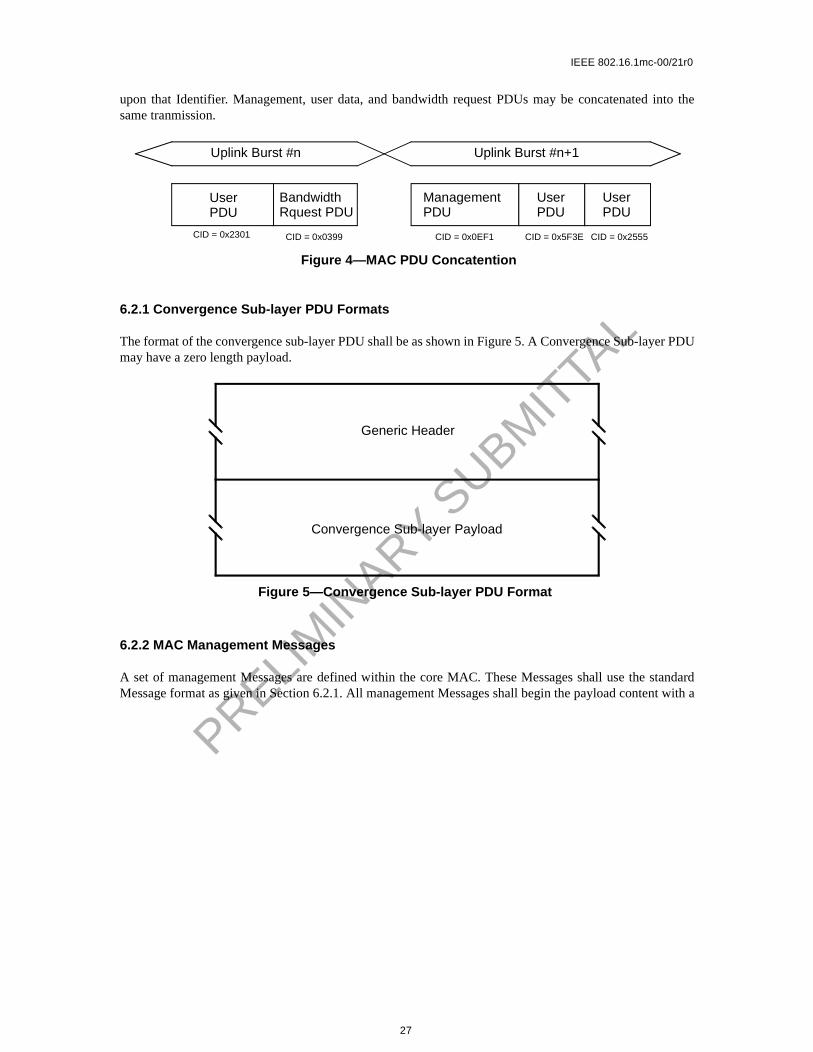
Multiple MAC PDUs may be concatenated into a single transmission in either the uplink or downlink direc-tions. Figure 4 illustrates this concept for an uplink burst transmission. Since each PDU is identifiied by aunique Connection Identifier, the receiving MAC entity is able to present the PDU to the correct SAP based
EKS 4 Encryption Key Sequence
The index of the Traffic Encryption Key and Initialization Vector used to encrypt the pay-load. This field is only meaningful if the Encryption Control field is set to zero. This field must be set to all zeros when the EC is 1.
FC 2 Fragmentation Control
Indicates the fragmentation state of the payload:00 = no fragmentation01 = last fragment10 = first fragment11 = continuing (middle) fragment
FSN 4 Fragmentation Sequence Number
Defines the sequence number of the current fragment. The initial fragment (FC=10) sets this field to 0. This field increments by one (modulo 16) for each fragment.
When fragmentation is not used (FC= 00), this field shall be set to 0.
GPI 7 Grants Per Interval
The number of grants required by a connection using UGS with Activity Detection
HCS 8 Header Check Sequence
An 8-bit field used to detect errors in the header. The generator polynomial is g(D)=D8 + D2 + D + 1.
HT 1 Header Type
0 = Generic Header1 = Bandwidth Request Header
LEN 11 Length
The length in bytes of the entire MAC header and any MAC PDU information that follows this specific header.
PBR 8 Piggy-Back Request
The number of bytes of uplink bandwidth requested by the CPE. The bandwidth request is for the CID. The request shall not include any PHY layer overhead.
PM 1 Poll-Me
0 = No action.1 = Used by the CPE to request a bandwidth poll.
SI 1 Slip Indicator
0 = No action1 = Used by the CPE to indicate a slip of uplink grants relative to the uplink queue depth.
Table 2—MAC Header Fields
Name Length(bits) Description
26
IEEE 802.16.1mc-00/21r0
PRELIM
INARY S
UBMIT
TAL
upon that Identifier. Management, user data, and bandwidth request PDUs may be concatenated into thesame tranmission.
6.2.1 Convergence Sub-layer PDU Formats
The format of the convergence sub-layer PDU shall be as shown in Figure 5. A Convergence Sub-layer PDUmay have a zero length payload.
6.2.2 MAC Management Messages
A set of management Messages are defined within the core MAC. These Messages shall use the standardMessage format as given in Section 6.2.1. All management Messages shall begin the payload content with a
Figure 4—MAC PDU Concatention
User Bandwidth ManagementPDURquest PDUPDU
UserPDU
UserPDU
Uplink Burst #n Uplink Burst #n+1
CID = 0x2301 CID = 0x0399 CID = 0x0EF1 CID = 0x5F3E CID = 0x2555
Figure 5—Convergence Sub-layer PDU Format
Convergence Sub-layer Payload
Generic Header
27

IEEE 802.16.1mc-00/21r0
PRELIM
INARY S
UBMIT
TAL
single byte field indicating the management Message type. The format of the management Message is givenFigure 6. The encoding of the Message type field is given in Table 3.
Table 3—MAC Management Messages
Type Message Name Message Description
1 PCD Physical Channel Descriptor
2 DS-MAP Downlink Access Definition
3 US-MAP Uplink Access Definition
4 RNG-REQ Ranging Request
5 RNG-RSP Ranging Response
6 REG-REQ Registration Request
7 REG-RSP Registration Response
8 REG-ACK Registration Acknowledge
9 PKM-REQ Privacy Key Management Request
10 PKM-RSP Privacy Key Management Response
11 DSA-REQ Dynamic Service Addition Request
12 DSA-RSP Dynamic Service Addition Response
13 DSA-ACK Dynamic Service Addition Acknowledge
14 DSC-REQ Dynamic Service Change Request
Figure 6—MAC Management Message Format
Management Message Type
Management Message Payload
Generic Header
Bit 0 8 15
28

IEEE 802.16.1mc-00/21r0
PRELIM
INARY S
UBMIT
TAL
6.2.2.1 Physical Channel Descriptor (PCD) Message
An Physical Channel Descriptor shall be transmitted by the BS at a periodic interval to define the character-istics of an physical channel. A separate PCD Message shall be transmitted for each active uplink.
15 DSC-RSP Dynamic Service Change Response
16 DSC-ACK Dynamic Service Change Acknowledge
17 DSD-REQ Dynamic Service Deletion Request
18 DSD-RSP Dynamic Service Deletion Response
19 DCC-REQ Dynamic Channel Change Request
20 DCC-RSP Dynamic Channel Change Response
21 MCA-REQ Multicast Assignment Request
22 MCA-RSP Multicast Assignment Response
23 DMC-REQ Downlink Modulation Change Request
24-255 Reserved for future use
Table 3—MAC Management Messages
Type Message Name Message Description
29

IEEE 802.16.1mc-00/21r0
PRELIM
INARY S
UBMIT
TAL
To provide for flexibility the message parameters following the channel ID shall be encoded in a type/length/value (TLV) form in which the type and length fields are each 1 octet long.
A BS shall generate PCDs in the format shown in Figure 7, including all of the following parameters:
Configuration Change Count
Incremented by one (modulo the field size) by the BS whenever any of the values of this channeldescriptor change. If the value of this count in a subsequent PCD remains the same, the CPE canquickly decide that the remaining fields have not changed, and may be able to disregard the remain-der of the message. This value is also referenced from the US-MAP messages.
Mini-Slot Size
The size T of the Mini-Slot for this uplink channel in units of Physical Slots. Allowable values are T= 2m, where m = 0,...7.
Uplink Channel ID
The identifier of the uplink channel to which this Message refers. This identifier is arbitrarily chosenby the BS and is only unique within the MAC-Sublayer domain.
Downlink Channel ID
Figure 7—Physical Channel Descriptor (PCD) Message Format
MAC Management Header
Uplink
TLV Encoded information for the overall channel
Mini-slot
TLV-encoded Burst Description (#n)
Channel IDConfigurationChange Count Size
DownlinkChannel ID
TLV-encoded Burst Description (#1)
0 8 16 24 31
30

IEEE 802.16.1mc-00/21r0
PRELIM
INARY S
UBMIT
TAL
The identifier of the downlink channel on which this Message has been transmitted. This identifier isarbitrarily chosen by the BS and is only unique within the MAC-Sublayer domain.
All other parameters are coded as TLV tuples. The type values used shall be those defined in Table 4, forchannel parameters, and Table 5, for uplink physical layer burst attributes. Channel-wide parameters (fromTable 4) shall preceed burst descriptors (type 1 below).
Table 4—Physical Channel Attributes
Name Type(1 byte)
Length(1 byte)
Value(Variable Length)
Burst Descriptor
1 May appear more than once; described below. The length is the number of bytes in the overall object, including embedded TLV items.
Symbol Rate
2 2 5 - 40 MBaud. The incremental rates are not yet defined for the PHY layer. The use of a TLV allows future clarification of this field without modification to the MAC.
Frequency 3 4 Uplink center frequency (kHz)
Preamble Pattern
4 1-128 Preamble superstring. All burst-specific preamble values are cho-sen as bit-substrings of this string.
The first byte of the Value field contains the first 8 bits of the superstring, with the first bit of the preamble superstring in the MSB position of the first Value field byte, the eighth bit of the pre-amble superstring in the LSB position of the first Value field byte; the second byte in the Value field contains the second eight bits of the superstring, with the ninth bit of the superstring in the MSB of the second byte and sixteenth bit of the preamble superstring in the LSB of the second byte, and so forth.
Tx/Rx Gap 5 1 The number of PS between the end of the downlink and uplink transmissions. This TLV is only used if the PHY Type field of the DS-MAP message is {0, 1} (TDD).
Rx/Tx Gap 6 1 The number of PS between the end of the uplink and downlink transmissions. This TLV is only used if the PHY Type field of the DS-MAP message is {0, 1} (TDD).
Shortened Downlink CPE Pre-amble Length
7 1 The number of PS...<TBD>
BS Trans-mit Power
8 1 Signed in units of 1dB
31

IEEE 802.16.1mc-00/21r0
PRELIM
INARY S
UBMIT
TAL
Burst Descriptors are compound TLV encodings that define, for each type of uplink usage interval, the phys-ical-layer characteristics that are to be used during that interval. The uplink interval usage codes are definedin the US-MAP Message.
A Burst Descriptor shall be included for each Interval Usage Code that is to be used in the allocation MAP.The Interval Usage Code shall be one of the values from Table 5.
Within each Burst Descriptor is an unordered list of Physical-layer attributes, encoded as TLV values. Theseattributes are shown in Table 5.
Figure 8—Top-Level Encoding for a Burst Descriptor
Type = 1 Length1..n
TLV codes for PHY parameters
MAC Management Header
(Burst Descriptor) IUC
Figure 9—Top-Level Encoding for a Burst Descriptor
Type > 1 Length and Value Information
Type > 1 Length and Value Information
Type = 1 First Burst Descriptor
Type = 1 Second Burst Descriptor
Other Type > 1 TLV Codes
32

IEEE 802.16.1mc-00/21r0
PRELIM
INARY S
UBMIT
TAL
Table 5—Uplink Physical Layer Burst Profile Parameters
Name Type(1 byte)
Length(1 byte)
Value(Variable Length)
Modula-tion Type
1 1 1 = QPSK, 2 = 16QAM, 3 = 64-QAM
Differen-tial Encod-ing
2 1 1 = on, 2 = off
Preamble Length
3 2 Up to 1024 bits. The value must be an integral number of symbols (a multiple of 2 for QPSK and 4 for 16QAM and 6 for 64QAM)
Preamble Value Off-set
4 2 Identifies the bits to be used for the preamble value. This is speci-fied as a starting offset into the Preamble Pattern (see <TBD>). That is, a value of zero means that the first bit of the preamble for this burst type is the value of the first bit of the Preamble Pattern. A value of 100 means that the preamble is to use the 101st and suc-ceeding bits from the Preamble Pattern. This value must be a multi-ple of the symbol size.
The first bit of the Preamble Pattern is the firstbit transmitted in the uplink burst.
FEC Error Correction (T)
5 1 0-10 (0 implies no FEC. The number of codeword parity bytes is 2*T)
FEC Code-word Infor-mation Bytes (k)
6 1 Fixed: 16 to 253 (assuming FEC on)Shortened: 16 to 253 (assuming FEC on)(Not used if no FEC, T=0)
Scrambler Seed
7 2 The 15-bit seed value left justified in the 2 byte field. Bit 15 is the MSB of the first byte and the LSB of the second byte is not used. (Not used if scrambler is off)
Maximum Burst Size
8 1 The maximum number of mini-slots that can be transmitted during this burst type. Absence of this configuration setting implies that the burst size is limited elsewhere. When the interval type is Short Data Grant this value MUST be present and greater than zero. (See <TBD>)
Guard Time Size
9 1 Number of symbol times which must follow the end of this burst. (Although this value may be derivable from other network and architectural parameters, it is included here to ensure that the CPEs and BS all use the same value.)
Last Code-word Length
10 1 1 = fixed; 2 = shortened
Scrambler on/off
11 1 1 = on; 2 = off
33
IEEE 802.16.1mc-00/21r0
PRELIM
INARY S
UBMIT
TAL
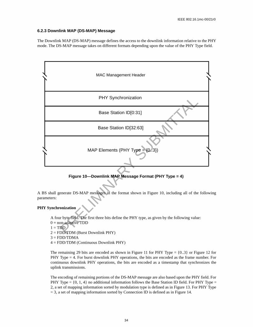
6.2.3 Downlink MAP (DS-MAP) Message
The Downlink MAP (DS-MAP) message defines the access to the downlink information relative to the PHYmode. The DS-MAP message takes on different formats depending upon the value of the PHY Type field.
A BS shall generate DS-MAP messages in the format shown in Figure 10, including all of the followingparameters:
PHY Synchronization
A four byte field. The first three bits define the PHY type, as given by the following value:0 = non-adaptive TDD1 = TDD2 = FDD/TDM (Burst Downlink PHY)3 = FDD/TDMA4 = FDD/TDM (Continuous Downlink PHY)
The remaining 29 bits are encoded as shown in Figure 11 for PHY Type = {0..3} or Figure 12 forPHY Type = 4. For burst downlink PHY operations, the bits are encoded as the frame number. Forcontinuous downlink PHY operations, the bits are encoded as a timestamp that synchronizes theuplink transmissions.
The encoding of remaining portions of the DS-MAP message are also based upon the PHY field. ForPHY Type = {0, 1, 4} no additional information follows the Base Station ID field. For PHY Type =2, a set of mapping information sorted by modulation type is defined as in Figure 13. For PHY Type= 3, a set of mapping information sorted by Connection ID is defined as in Figure 14.
Figure 10—Downlink MAP Message Format (PHY Type = 4)
MAC Management Header
Base Station ID[0:31]
PHY Synchronization
Base Station ID[32:63]
MAP Elements (PHY Type = {0..3})
34

IEEE 802.16.1mc-00/21r0
PRELIM
INARY S
UBMIT
TAL
Figure 11—PHY Synchronization Field (PHY Type = {0..3})
PHY Type Hyperframe Number[14..7]
Hyperframe Number[6:0]MultiframeNumber
FrameNumber
Figure 12—PHY Synchronization Field (PHY Type = 1)
PHY Type Uplink Timestamp[29:16]
Uplink Timestamp[15:0]
Figure 13—Downlink TDM MAP Message Element Format
QAM-16 Physical Slot Start
Downlink MAP Message
QAM-64 Physical Slot Start
End Physical Slot
35

IEEE 802.16.1mc-00/21r0
PRELIM
INARY S
UBMIT
TAL
Figure 14—Downlink TDMA MAP Message Element Format
Physical Slot Start
Downlink MAP Message
Physical Slot Start
Connection Identifier
Connection Identifier
Connection Identifier Physical Slot Start
36

IEEE 802.16.1mc-00/21r0
PRELIM
INARY S
UBMIT
TAL
6.2.4 Uplink MAP Message
Uplink Channel ID
The identifier of the uplink channel to which this Message refers.
Figure 15—Uplink MAP Message Format
PCD Channel ID PCD Count Number of Elements
Allocation Start Time
Acknowledgement Time
Ranging BackoffStart
Ranging BackoffEnd
Data BackoffStart
Data BackoffEnd
IUC OffsetConnection ID
IUC Offset = 0Connection ID
IUC=7 Offset = map lengthConnection ID = 0
IUC Offset = map lengthConnection ID(acknowledgement or data grant pending)
IUC Offset = map lengthConnection ID(acknowledgement or data grant pending)
MAC Management Header
0 8 16 24 31
37

IEEE 802.16.1mc-00/21r0
PRELIM
INARY S
UBMIT
TAL
PCD Count
Matches the value of the Configuration Change Count of the PCD which describes the burst param-eters which apply to this map.
Number Elements
Number of information elements in the map.
Alloc Start Time
Effective start time of the uplink allocation defined by the US-MAP in units of mini-slots. The starttime is relative to the start of a frame in which US-MAP message is transmitted (PHY Type ={0..3}) or from BS initialization (PHY Type = 4).
Ack Time
Latest time processed in uplink in units of mini-slots. This time is used by the CPE for collisiondetection purposes. The ack time is relative to the start of a frame in which US-MAP message istransmitted (PHY Type = {0..3}) or from BS initialization (PHY Type = 4).
Ranging Backoff Start
Initial back-off window size for initial ranging contention, expressed as a power of 2. Values of nrange 0-15 (the highest order bits must be unused and set to 0).
Ranging Backoff End
Final back-off window size for initial ranging contention, expressed as a power of 2. Values of nrange 0-15 (the highest order bits must be unused and set to 0).
Data Backoff Start
Initial back-off window size for contention data and requests, expressed as a power of 2. Values of nrange 0-15 (the highest order bits must be unused and set to 0).
Data Backoff End
Final back-off window size for contention data and requests, expressed as a power of 2. Values of nrange 0-15 (the highest order bits must be unused and set to 0).
MAP Information Elements
Information elements define uplink bandwidth allocations. Each US-MAP message shall contain atleast one Information Element. The format of the IE shall be as shown in Figure 16. Each IE consistsof three fields: a Connection Identifer, an Interval Usage Code, and an offset.
The Connection Identifier represent the assignment of the IE to either a unicast, multicast, or broad-cast address. When specifically addressed to allocate a bandwidth grant, the CID may be either theBasic CID of the CPE or a Traffic CID for one of the connections of the CPE. A four-bit IntervalUsage Code (IUC) shall be used to define the type of uplink access and the burst type associatedwith that access. Table 6 defines the use of the IUCs. The offset shall be the length from the start ofthe previous IE to the start of this IE in units of mini-slots. The first IE shall have an offset of 0.
38

IEEE 802.16.1mc-00/21r0
PRELIM
INARY S
UBMIT
TAL
Table 6—Uplink MAP Information Elements
IE Name
IntervalUsageCode(IUC)
Connection ID Mini-slot Offset
Request 1 any Starting offset of REQ region
InitialMaintenance
2 broadcast Starting offset of MAINT region (used in Initial Ranging)
StationMaintenance
3 unicast Starting offset of MAINT region (used in Periodic Ranging)
Short Data Grant
4 unicast Starting offset of Data Grant assignmentIf inferred length = 0, then it is a Data Grant pending.
Long Data Grant
5 unicast Starting offset of Data Grant assignmentIf inferred length = 0, then it is a Data Grant Pending
Short Data Grant 2
6 unicast Starting offset of Data Grant 2 assignmentIf inferred length = 0, then it is a Data Grant pending.
Long Data Grant 2
7 unicast Starting offset of Data Grant 2 assignmentIf inferred length = 0, then it is a Data Grant pending.
Short Data Grant 3
8 unicast Starting offset of Data Grant 3 assignmentIf inferred length = 0, then it is a Data Grant pending.
Long Data Grant 3
9 unicast Starting offset of Data Grant 3 assignmentIf inferred length = 0, then it is a Data Grant pending.
Null IE 10 zero Ending offset of the previous grant.Used to bound the length of the last actual interval allocation.
Data Ack 11 unicast BS sets to map length
Reserved 12-14 any Reserved
Expansion 15 expanded IUC # of additional 32-bit words in this IE
Figure 16—US-MAP Information Element
Interval
Connection Identifier
Offset
Bit 0 8 15
Usage Code
39

IEEE 802.16.1mc-00/21r0
PRELIM
INARY S
UBMIT
TAL
6.2.5 Ranging Request (RNG-REQ) Message
40

IEEE 802.16.1mc-00/21r0
PRELIM
INARY S
UBMIT
TAL
If zero, then all previous Ranging Response attributes have been applied prior to transmittting thisrequest. If nonzero then this is time estimated to be needed to complete assimilation of rangingparameters. Note that only equalization can be deferred. Units are in unsigned centiseconds (10msec).
All other parameters are coded as TLV tuples.
Modulation Type
An optional parameter. The Modulation type requested by the BS for downlink traffic. The BS deter-mines the appropriate modulation type to use based upon measurements of the downlink RF channelrelative to the Modulation Transition Thresholds defined in the RNG-RSP Message.
6.2.5.1 RNG-REQ TLV Encodings
The type values used MUST be those defined in Table 7. These are unique within the ranging request Mes-sage but not across the entire MAC Message set. The type and length fields MUST each be 1 octet in length.
6.2.6 Ranging Response (RNG-RSP) Message
A Ranging Response shall be transmitted by a BS in response to received RNG-REQ. It may be noted that,from the point of view of the CPE, reception of a Ranging Response is stateless. In particular, the CPE shallbe prepared to receive a Ranging Response at any time, not just following a Ranging Request.
The RNG-RSP Message shall be transmitted using QPSK modulation.
To provide for flexibility, the Message parameters following the Uplink Channel ID shall be encoded in atype/length/value (TLV) form.
Table 7—Ranging Request Message Encodings
Name Type(1 byte)
Length(1 byte)
Value(Variable Length)
ModulationType
1 1 1 = QPSK, 2 = 16-QAM, 3 = 64-QAM
Reserved 2-255 n Reserved for future use
41

IEEE 802.16.1mc-00/21r0
PRELIM
INARY S
UBMIT
TAL
A BS shall generate Ranging Responses in the form shown in Figure 18, including all of the followingparameters:
CID
If the modem is being instructed by this response to move to a different channel, this is initialization-CID. Otherwise, this is the CID from the corresponding RNG-REQ to which this response refers,except that if the corresponding RNG-REQ was an initial ranging request specifying a initializationCID, then this is the assigned temporary CID.
Uplink Channel ID
The identifier of the uplink channel on which the BS received the RNG-REQ to which this responserefers.
Ranging Status
Used to indicate whether uplink Messages are received within acceptable limits by BS.
All other parameters are coded as TLV tuples.
Timing Adjust Information
The time by which to offset frame transmission so that frames arrive at the expected mini-slot timeat the BS.
Power Adjust Information
Specifies the relative change in transmission power level that the CPE is to make in order that trans-missions arrive at the BS at the desired power.
Figure 18—RNG-RSP Message Format
Connection ID UplinkChannel ID
TLV Encoded Information
(from RNG-REQ)
MAC Management Header
42

IEEE 802.16.1mc-00/21r0
PRELIM
INARY S
UBMIT
TAL
Frequency Adjust Information
Specifies the relative change in transmission frequency that the CPE is to make in order to bettermatch the BS. (This is fine-frequency adjustment within a channel, not re-assignment to a differentchannel)
CPE Transmitter Equalization Information
This provides the equalization coefficients for the pre-equalizer.
Downlink Frequency Override
An optional parameter. The downlink frequency with which the modem should redo initial ranging.
Uplink Channel ID Override
An optional parameter. The identifier of the uplink channel with which the modem should redo ini-tial ranging.
16-QAM Threshold
An optional parameter. The threshold for transition between QPSK and 16-QAM on a downlinkchannel is specified by the BS for use by the CPE.
64-QAM Threshold
An optional parameter. The threshold for transition between 16-QAM and 64-QAM on a downlinkchannel is specified by the BS for use by the CPE.
Threshold Delta
An optional parameter. The delta about which a hysteresis is defined for transition of the CPEbetween modulation types. Used by the CPE in conjuction with the 16-QAM and 64-QAM Thresh-olds to determine when to request a modulation change for the downlink channel.
Modulation Type
An optional parameter. The maximum allow set of Modulation types allowed for the CPE for down-link traffic. This parameter is sent in response to the RNG-REQ Modulation Type from the CPE.The CPE responds with the maximum allowed set of modulation types based upon the combinationof the requested modulation type and the maximum allowable modulation type determined at regis-tration or from a dynamic service operation.
6.2.6.1 RNG-RSP TLV Encodings
The type values used shall be those defined in Table 8 and Figure 21. These are unique within the rangingresponse Message but not across the entire MAC Message set. The type and length fields shall each be 1octet in length.
43

IEEE 802.16.1mc-00/21r0
PRELIM
INARY S
UBMIT
TAL
Table 8—Ranging Response Message Encodings
Name Type(1 byte)
Length(1 byte)
Value(Variable Length)
Timing Adjust
1 4 Tx timing offset adjustment (signed 32-bit, units of mini-slot time/64)
Power Level Adjust
2 1 Tx Power offset adjustment (signed 8-bit, 1/4-dB units)
Offset Fre-quency Adjust
3 4 Tx frequency offset adjustment (signed 32-bit, Hz units)
Transmit Equaliza-tion Adjust
4 n Tx equalization data - see details below
Ranging Status
5 1 1 = continue, 2 = abort, 3 = success
Downlink frequency override
6 4 Center frequency of new downlink channel in kHz
Uplink channel ID override
7 1 Identifier of the new uplink channel.
16-QAM Threshold
8 1 C/I+N for minimum 16-QAM operation in 0.25 dB.
64-QAM Threshold
9 1 C/I+N for minimum 64-QAM operation in 0.25 dB.
Threshold Delta
10 1 Hysteresis delta for modulation threholds in 0.25 dB.
Modula-tion Type
11 1 1 = QPSK, 2 = QPSK or 16-QAM, 3 = QPSK or 16/64-QAM
Reserved 12-255 n Reserved for future use
44

IEEE 802.16.1mc-00/21r0
linear coeffi-
ts MAYe second
PRELIM
INARY S
UBMIT
TAL
The number of forward taps per symbol shall be in the range of 1 to 4. The main tap location refers to theposition of the zero delay tap, between 1 and N. For a symbol-spaced equalizer, the number of forward tapsper symbol field shall be set to “1”. The number of reverse taps (M) field shall be set to “0” for a equalizer. The total number of taps MAY range up to 64. Each tap consists of a real and imaginarycient entry in the table.
If more than 255 bytes are needed to represent equalization information, then several type-4 elemenbe used. Data shall be treated as if byte-concatenated, that is, the first byte after the length field of thtype-4 element is treated as if it immediately followed the last byte of the first type-4 element.
Figure 19—Generalized Decision Feedback Equalization Coefficients
last coefficient FN (imag)
first reverse coefficient D1(imag)
last reverse coefficient DM(imag)
last coefficient FN (real)
first reverse coefficient D1(real)
last reverse coefficient DM(real)
type4
length number of forwardtaps per symbol
number offorward taps (N)
number ofreverse taps (M)
main taplocation
first coefficient F1 (real) first coefficient F1 (imag)
Figure 20—Generalized Equalizer Tap Location Definition
F3
D5
F4
D4
F5
D3
F6
D2
F2
D6
F1
DM
Z-T
Z-R
FN
D1
EqualizerInput
EqualizerOutput
Z-R Z-R Z-R Z-R Z-R
Z-T Z-T Z-T Z-T Z-T Z-T
R = T, T/2, T/4
45

IEEE 802.16.1mc-00/21r0
PRELIM
INARY S
UBMIT
TAL
6.2.7 Registration Request (REG-REQ) Message
A Registration Request MUST be transmitted by a CPE at initialization after receipt of a CPE parameter file.
To provide for flexibility, the Message parameters following the CID shall be encoded in a type/length/valueform.
A CPE shall generate Registration Requests in the form shown in Figure 21, including the following param-eters:
CID
Temporary CID for this CPE.
All other parameters are coded as TLV tuples as defined in Section 6.12.
Registration Requests can contain many different TLV parameters, some of which are set by the CPEaccording to its configuration file and some of which are generated by the CPE itself. If found in the Config-uration File, the following Configuration Settings shall be included in the Registration Request.
Configuration File Settings:
— Downlink Frequency Configuration Setting— Uplink Channel ID Configuration Setting— Network access Control Object— Uplink Service Flow Configuration Setting— Downlink Service Flow Configuration Setting— Privacy Configuration Setting— Maximum Number of Subscribers— Privacy Enable Configuration Setting
Figure 21—REG-REQ Message Format
Connection ID
TLV Encoded Information
MAC Management Header
46

IEEE 802.16.1mc-00/21r0
PRELIM
INARY S
UBMIT
TAL
— TFTP Server Timestamp— TFTP Server Provisioned Modem address— Downlink Modulation Configuration Setting— Vendor-Specific Information Configuration Setting— CPE MIC Configuration Setting— BS MIC Configuration Setting
The CPE shall forward the vendor specific configuration settings to the BS in the same order in which they werereceived in the configuration file to allow the Message integrity check to be performed.
The following registration parameter shall be included in the Registration Request.
Vendor Specific Parameter:
— Vendor ID Configuration Setting (Vendor ID of CPE)
The following registration parameter MUST also be included in the Registration Request.
— Modem Capabilities Encodings
The following registration parameter MAY also be included in the Registration Request.
— Modem IP address
The following Configuration Settings shall not be forwarded to the BS in the Registration Request.
— Software Upgrade Filename — Software Upgrade TFTP Server IP address— SNMP Write-access Control— SNMP MIB Object— CPE EUI-64 MAC address— HMAC Digest— End Configuration Setting— Pad Configuration Setting
6.2.8 Registration Response (REG-RSP) Message
A Registration Response MUST be transmitted by BS in response to received REG-REQ.
47

IEEE 802.16.1mc-00/21r0
PRELIM
INARY S
UBMIT
TAL
To provide for flexibility, the Message parameters following the Response field MUST be encoded in a TLVformat.
A BS shall generate Registration Responses in the form shown in Figure 22, including both of the followingparameters:
CID from Corresponding REG-REQ
CID from corresponding REG-REQ to which this response refers. (This acts as a transaction identi-fier)
CID #2
CID for secondary management purposes
Response
0 = Okay1 = Authentication Failure2 = Class of Service Failure
Failures apply to the entire Registration Request. Even if only a single requested Service Flow is invalid or unde-liverable the entire registration is failed.
If the REG-REQ was successful and contained Service Flow Parameters, the REG-RSP MUST contain:
Service Flow Parameters
All the Service Flow Parameters from the REG-REQ, plus the Connection ID assigned by the BS.Every Service Flow that contained a Service Class Name that was admitted/activated MUST be
Figure 22—REG-RSP Message Format
Connection ID
TLV Encoded Information
(from corresponding REG-REQ)Connection ID
(2nd management connection)
Response
MAC Management Header
48

IEEE 802.16.1mc-00/21r0
sponsetet.
he BSt recog-
hand-
BS. ItG-RSP.
PRELIM
INARY S
UBMIT
TAL
expanded into the full set of TLVs defining the Service Flow. Every uplink Service Flow that wasadmitted/activated1 MUST have a Service Identifier assigned by the BS. A Service Flow that wasonly provisioned will include only those QoS parameters that appeared in the REG-REQ, plus theassigned Connection ID.
If the REG-REQ failed and contained Service Flow Parameters, the REG-RSP MUST contain the following:
Service Flow Error Set
A Service Flow Error Set and identifying Service Flow Reference MUST be included for everyfailed Service Flow in the corresponding REG-REQ. Every Service Flow Error Set MUST includeevery specific failed QoS Parameter of the corresponding Service Flow.
Service Class Name expansion always occurs at admission time. Thus, if a Registration-Request contains aService Flow Reference and a Service Class Name for deferred admission/activation, the Registration-Response MUST NOT include any additional QoS Parameters except the Service Flow Identifier.
All other parameters are coded as TLV tuples:
Modem Capabilities
The BS response to the capabilities of the modem (if present in the Registration Request)
Vendor-Specific Data
As defined in Section 6.12— Vendor ID Configuration Setting (vendor ID of BS)— Vendor-specific extensions
Note: The temporary CID MUST no longer be used once the REG-RSP is received.
6.2.8.1 Encodings
The type values used MUST be those shown below. These are unique within the Registration ReMessage but not across the entire MAC Message set. The type and length fields MUST each be 1 oc
Modem Capabilities
This field defines the BS response to the modem capability field in the Registration Request. Tresponds to the modem capabilities to indicate whether they may be used. If the BS does nonize a modem capability, it must return this as “off” in the Registration Response.
Only capabilities set to “on” in the REG-REQ may be set “on” in the REG-RSP as this is the shake indicating that they have been successfully negotiated.
Encodings are as defined for the Registration Request.
6.2.9 Registration Acknowledge (REG-ACK) Message
A Registration Acknowledge MUST be transmitted by the CPE in response to a REG-RSP from theconfirms acceptance by the CPE of the QoS parameters of the flow as reported by the BS in it REThe format of a REG-ACK MUST be as shown in Figure 23.
1The ActiveQoSParamSet or AdmittedQoSParamSet is non-null.
49

IEEE 802.16.1mc-00/21r0
PRELIM
INARY S
UBMIT
TAL
The parameter MUST be as follows:
CID from Corresponding REG-RSP
CID from corresponding REG-RSP to which this acknowledgment refers. (This acts as a transactionidentifier)
Confirmation Code
The appropriate Confirmation Code (refer to Section 6.12) for the entire corresponding RegistrationResponse.
The CPE MUST forward all provisioned Service Flows to the BS. Since any of these provisioned items canfail, the REG-ACK MUST include Error Sets for all failures related to these provisioned items.
Service Flow Error Set
The Service Flow Error Set of the REG-ACK Message encodes specifics of any failed ServiceFlows in the REG-RSP Message. A Service Flow Error Set and identifying Service Flow ReferenceMUST be included for every failed QoS Parameter of every failed Service Flow in the correspond-ing REG-RSP Message. This parameter MUST be omitted if the entire REG-REQ/RSP is success-ful.
Note: Per Service Flow acknowledgment is necessary not just for synchronization between the CPE and BS, but also tosupport use of the Service Class Name. Since the CPE may not know all of the Service Flow parameters associated witha Service Class Name when making the Registration Request, it may be necessary for the CPE to NAK a RegistrationResponse if it has insufficient resources to actually support this Service Flow.
Figure 23—REG-ACK Message Format
Connection ID
TLV Encoded Information
(from corresponding REG-RSP)Connection ID
(2nd management connection)
ConfirmationCode
MAC Management Header
50

IEEE 802.16.1mc-00/21r0
CPE’s
ntifiert, Keyt event.
ffectonsendingests,
T be
lar stateation
PRELIM
INARY S
UBMIT
TAL
6.2.10 Privacy Key Management — Request (PKM-REQ) Message
Privacy Key Management protocol Messages transmitted from the CPE to the BS shall use the form shownin Figure 24.
Parameters MUST be as follows:
PKM Code
The Code field is one octect and identifies the type of PKM packet. When a packet is recieved withan invalid Code field, it shall be silently discarded. The Code values are defined in Section 7.2.5.1.
PKM Identifier
The Identifier field is one octect. A CPE uses the identifier to match a BS response to the requests.
The CPE MUST change (e.g., increment, wrapping around to 0 after reaching 255) the Idefield whenever it issues a new PKM Message. A "new" Message is an Authorization RequesRequest or SA Map Request that is not a retransmission being sent in response to a TimeouFor retransmissions, the Identifier field MUST remain unchanged.
The Identifier field in Authentication Information Messages, which are informative and do not eany response messaging, MAY be set to zero. The Identifier field in a CMTS’s BPKM respMessage MUST match the Identifier field of the BPKM Request Message the CMTS is respoto. The Identifier field in TEK Invalid Messages, which are not sent in response to BPKM requMUST be set to zero. The Identifier field in unsolicited Authorization Invalid Messages MUSset to zero.
On reception of a BPKM response Message, the CPE associates the Message with a particumachine (the Authorization state machine in the case of Authorization Replies, Authoriz
Figure 24—PKM-REQ Message Format
TLV Encoded Information
LengthPKM Code PKM Identifier
MAC Management Header
51

IEEE 802.16.1mc-00/21r0
PRELIM
INARY S
UBMIT
TAL
Rejects, and Authorization Invalids; a particular TEK state machine in the case of Key Replies, KeyRejects and TEK Invalids; a particular SA Mapping state machine in the case of SA Map Repliesand SA Map Rejects).
A CPE MAY keep track of the Identifier of its latest, pending Authorization Request. The CPEMAY silently discard Authorization Replies and Authorization Rejects whose Identifier fields donot match those of the pending requests.
A CPE MAY keep track of the Identifier of its latest, pending Key Request. The CPE MAY silentlydiscard Key Replies and Key Rejects whose Identifier fields do not match those of the pendingrequests.
A CPE MAY keep track of the Identifier of its latest, pending SA Map Request. The CPE MAYsilently discard SA Map Replies and SA Map Rejects whose Identifier fields do not match those ofthe pending requests.
Length
The Length field is two octets. It indicates the length of the Attribute fields in octets. The lengthfield does not include the Code, Identifier and Length fields. Octets outside the range of the Lengthfield MUST be treated as padding and ignored on reception. If the packet is shorter than the Lengthfield indicates, it SHOULD be silently discarded. The minimum length is 0 and maximum length is<TBD>.
All other parameters are encoded as TLV tuples as defined in Section 6.12.
6.2.11 Privacy Key Management — Response (PKM-RSP) Message
Privacy Key Management protocol Messages transmitted from the BS to the CPEshall use the form shownin Figure 25.
Figure 25—PKM-RSP Message Format
TLV Encoded Information
LengthPKM Code PKM Identifier
MAC Management Header
52

IEEE 802.16.1mc-00/21r0
PRELIM
INARY S
UBMIT
TAL
6.2.12 Dynamic Service Addition — Request (DSA-REQ) Message
A Dynamic Service Addition Request MAY be sent by a CPE or BS to create a new Service Flow.
A CPE or BS MUST generate DSA-REQ Messages in the form shown in Figure 26 including the followingparameter:
Transaction ID
Unique identifier for this transaction assigned by the sender.
All other parameters are coded as TLV tuples as defined in Section 6.12. A DSA-REQ Message MUSTNOT contain parameters for more than one Service Flow in each direction, i.e., a DSA-REQ MessageMUST contain parameters for either a single uplink Service Flow, or for a single downlink Service Flow, orfor one uplink and one downlink Service Flow.
The DSA-REQ Message MUST contain:
Service Flow Parameters
Specification of the Service Flow’s traffic characteristics and scheduling requirements.
If Privacy is enabled, the DSA-REQ Message MUST contain:
HMAC-Digest
Figure 26—DSA-REQ Message Format
Transaction ID
TLV Encoded Information
MAC Management Header
53

IEEE 802.16.1mc-00/21r0
list.
Flows. DSA-spect to
all, of
ction
sociated
PRELIM
INARY S
UBMIT
TAL
The HMAC-Digest Attribute is a keyed Message digest (to authenticate the sender). The HMAC-Digest Attribute MUST be the final Attribute in the Dynamic Service Message’s Attribute (Refer to Section 6.12)
6.2.12.1 CPE-Initiated Dynamic Service Addition
CPE-initiated DSA-Requests MUST use the Service Flow Reference to link Classifiers to Service Values of the Service Flow Reference are local to the DSA Message; each Service Flow within theRequest MUST be assigned a unique Service Flow Reference. This value need not be unique with rethe other service flows known by the sender.
CPE-initiated DSA-Requests MAY use the Service Class Name (refer to <TBD>) in place of some, orthe QoS Parameters.
6.2.12.2 BS-Initiated Dynamic Service Addition
BS-initiated DSA-Requests for Uplink Service Flows MUST also include a Connection ID. ConneIdentifiers are unique within the MAC domain.
BS-initiated DSA-Requests for named Service Classes MUST include the QoS Parameter Set aswith that Service Class.
6.2.13 Dynamic Service Addition — Response (DSA-RSP) Message
A Dynamic Service Addition Response shall be generated in response to a received DSA-Request. The for-mat of a DSA-RSP MUST be as shown in Figure 27.
Parameters MUST be as follows:
Figure 27—DSA-RSP Message Format
Transaction ID
TLV Encoded Information
ConfirmationCode
MAC Management Header
54
IEEE 802.16.1mc-00/21r0
list.
ion ID.ntain a
e addi-ss. If the MUST
Serviceues as
ify the
aram-
PRELIM
INARY S
UBMIT
TAL
Transaction ID
Transaction ID from corresponding DSA-REQ.
Confirmation Code
The appropriate Confirmation Code for the entire corresponding DSA-Request.
All other parameters are coded as TLV tuples as defined in Section 6.12.
If the transaction is successful, the DSA-RSP MAY contain the following:
Service Flow Parameters
The complete specification of the Service Flow MUST be included in the DSA-RSP only if itincludes a newly assigned Connection Identifier or an expanded Service Class Name.
If the transaction is unsuccessful, the DSA-RSP MUST include:
Service Flow Error Set
A Service Flow Error Set and identifying Service Flow Reference/Identifier MUST be included forevery failed Service Flow in the corresponding DSA-REQ Message. Every Service Flow Error SetMUST include every specific failed QoS Parameter of the corresponding Service Flow. This param-eter MUST be omitted if the entire DSA-REQ is successful.
If Privacy is enabled, the DSA-RSP Message MUST contain:
HMAC-Digest
The HMAC-Digest Attribute is a keyed Message digest (to authenticate the sender). The HMAC-Digest Attribute MUST be the final Attribute in the Dynamic Service Message’s Attribute (Refer to Appendix <TBD>)
6.2.13.1 CPE-Initiated Dynamic Service Addition
The BS’s DSA-Response for Service Flows that are successfully added MUST contain a ConnectThe DSA-Response for successfully Admitted or Active uplink QoS Parameter Sets MUST also coConnection ID.
If the corresponding DSA-Request uses the Service Class Name (refer to <TBD>) to request serviction, a DSA-Response MUST contain the QoS Parameter Set associated with the named Service ClaService Class Name is used in conjunction with other QoS Parameters in the DSA-Request, the BSaccept or reject the DSA-Request using the explicit QoS Parameters in the DSA-Request. If theseFlow Encodings conflict with the Service Class attributes, the BS MUST use the DSA-Request valoverrides for those of the Service Class.
If the transaction is unsuccessful, the BS MUST use the original Service Flow Reference to identfailed parameters in the DSA-RSP.
6.2.13.2 BS-Initiated Dynamic Service Addition
If the transaction is unsuccessful, the CPE MUST use the Connection Identifier to identify the failed peters in the DSA-RSP.
55

IEEE 802.16.1mc-00/21r0
PRELIM
INARY S
UBMIT
TAL
6.2.14 Dynamic Service Addition — Acknowledge (DSA-ACK) Message
A Dynamic Service Addition Acknowledge MUST be generated in response to a received DSA-RSP. Theformat of a DSA-ACK MUST be as shown in Figure 28.
Parameters MUST be as follows:
Transaction ID
Transaction ID from corresponding DSA-Response.
Confirmation Code
The appropriate Confirmation Code (refer to<TBD>) for the entire corresponding DSA-Response.2
All other parameters are coded TLV tuples.
Service Flow Error Set
The Service Flow Error Set of the DSA-ACK Message encodes specifics of any failed ServiceFlows in the DSA-RSP Message. A Service Flow Error Set and identifying Service Flow ReferenceMUST be included for every failed QoS Parameter of every failed Service Flow in the correspond-ing DSA-REQ Message. This parameter MUST be omitted if the entire DSA-REQ is successful.
2The confirmation code is necessary particularly when a Service Class Name (refer to Section <TBD>) is used in the DSA-Request. Inthis case, the DSA-Response could contain Service Flow parameters that the CPE is unable to support (either temporarily or as config-ured).
Figure 28—DSA-ACK Message Format
Transaction ID
TLV Encoded Information
ConfirmationCode
MAC Management Header
56
IEEE 802.16.1mc-00/21r0
list.
PRELIM
INARY S
UBMIT
TAL
If Privacy is enabled, the DSA-ACK Message MUST contain:
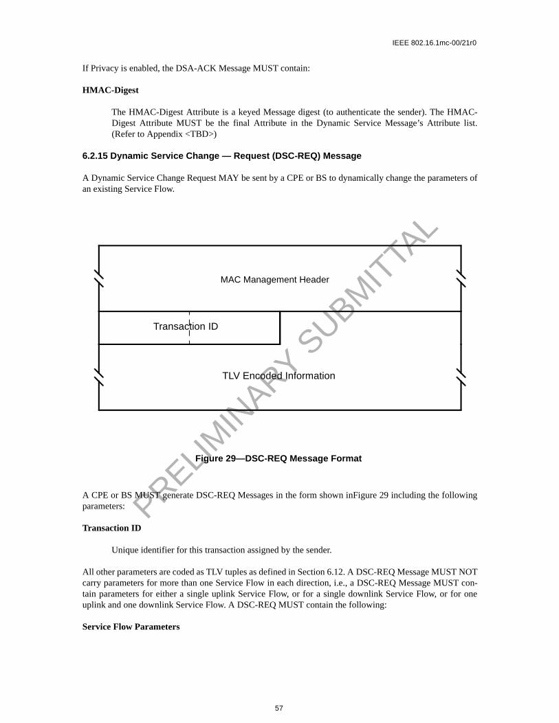
HMAC-Digest
The HMAC-Digest Attribute is a keyed Message digest (to authenticate the sender). The HMAC-Digest Attribute MUST be the final Attribute in the Dynamic Service Message’s Attribute (Refer to Appendix <TBD>)
6.2.15 Dynamic Service Change — Request (DSC-REQ) Message
A Dynamic Service Change Request MAY be sent by a CPE or BS to dynamically change the parameters ofan existing Service Flow.
A CPE or BS MUST generate DSC-REQ Messages in the form shown inFigure 29 including the followingparameters:
Transaction ID
Unique identifier for this transaction assigned by the sender.
All other parameters are coded as TLV tuples as defined in Section 6.12. A DSC-REQ Message MUST NOTcarry parameters for more than one Service Flow in each direction, i.e., a DSC-REQ Message MUST con-tain parameters for either a single uplink Service Flow, or for a single downlink Service Flow, or for oneuplink and one downlink Service Flow. A DSC-REQ MUST contain the following:
Service Flow Parameters
Figure 29—DSC-REQ Message Format
Transaction ID
TLV Encoded Information
MAC Management Header
57

IEEE 802.16.1mc-00/21r0
. The If thereplace-MUSTr.
MAC-list.
PRELIM
INARY S
UBMIT
TAL
Specification of the Service Flow’s new traffic characteristics and scheduling requirementsAdmitted and Active Quality of Service Parameter Sets currently in use by the Service Flow.DSC Message is successful and it contains Service Flow parameters, but does not contain ment sets for both Admitted and Active Quality of Service Parameter Sets, the omitted set(s) be set to null. If included, the Service Flow Parameters MUST contain a Service Flow Identifie
If Privacy is enabled, a DSC-REQ MUST also contain:
HMAC-Digest
The HMAC-Digest Attribute is a keyed Message digest (to authenticate the sender). The HDigest Attribute MUST be the final Attribute in the Dynamic Service Message’s Attribute (Refer to <TBD>)
6.2.16 Dynamic Service Change — Response (DSC-RSP) Message
A Dynamic Service Change Response MUST be generated in response to a received DSC-REQ. The formatof a DSC-RSP MUST be as shown in Figure 30.
Parameters MUST be as follows:
Transaction ID
Transaction ID from corresponding DSC-REQ
Confirmation Code
The appropriate Confirmation Code (refer to <TBD>) for the corresponding DSC-Request.
Figure 30—DSC-RSP Message Format
Transaction ID
TLV Encoded Information
ConfirmationCode
MAC Management Header
58
IEEE 802.16.1mc-00/21r0
list.
PRELIM
INARY S
UBMIT
TAL
All other parameters are coded as TLV tuples as defined in Section 6.12.
If the transaction is successful, the DSC-RSP MAY contain the following:
Service Flow Parameters
The complete specification of the Service Flow MUST be included in the DSC-RSP only if itincludes a newly assigned Connection Identifier or an expanded Service Class Name. If a ServiceFlow Parameter set contained an uplink Admitted QoS Parameter Set and this Service Flow does nothave an associated CID, the DSC-RSP MUST include a CID. If a Service Flow Parameter set con-tained a Service Class Name and an Admitted QoS Parameter Set, the DSC-RSP MUST include theQoS Parameter Set corresponding to the named Service Class. If specific QoS Parameters were alsoincluded in the Classed Service Flow request, these QoS Parameters MUST be included in the DSC-RSP instead of any QoS Parameters of the same type of the named Service Class.
If the transaction is unsuccessful, the DSC-RSP MUST contain the following:
Service Flow Error Set
A Service Flow Error Set and identifying Connection ID MUST be included for every failed ServiceFlow in the corresponding DSC-REQ Message. Every Service Flow Error Set MUST include everyspecific failed QoS Parameter of the corresponding Service Flow. This parameter MUST be omittedif the entire DSC-REQ is successful.
Regardless of success or failure, if Privacy is enabled for the CPE the DSC-RSP MUST contain:
HMAC-Digest
The HMAC-Digest Attribute is a keyed Message digest (to authenticate the sender). The HMAC-Digest Attribute MUST be the final Attribute in the Dynamic Service Message’s Attribute (Refer to <TBD>)
6.2.17 Dynamic Service Change — Acknowledge (DSC-ACK) Message
A Dynamic Service Change Acknowledge MUST be generated in response to a received DSC-RSP. The for-mat of a DSC-ACK MUST be as shown in Figure 31.
59

IEEE 802.16.1mc-00/21r0
list.
PRELIM
INARY S
UBMIT
TAL
Parameters MUST be as follows:
Transaction ID
Transaction ID from the corresponding DSC-REQ
Confirmation Code
The appropriate Confirmation Code (refer to <TBD>) for the entire corresponding DSC-Response.
All other parameters are coded TLV tuples.
Service Flow Error Set
The Service Flow Error Set of the DSC-ACK Message encodes specifics of any failed ServiceFlows in the DSC-RSP Message. A Service Flow Error Set and identifying Service Flow IdentifierMUST be included for every failed QohS Parameter of each failed Service Flow in the correspond-ing DSC-RSP Message. This parameter MUST be omitted if the entire DSC-RSP is successful.
If Privacy is enabled, the DSC-ACK Message MUST contain:
HMAC-Digest
The HMAC-Digest Attribute is a keyed Message digest (to authenticate the sender). The HMAC-Digest Attribute MUST be the final Attribute in the Dynamic Service Message’s Attribute (Refer to <TBD>)
Figure 31—DSC-ACK Message Format
Transaction ID
TLV Encoded Information
ConfirmationCode
MAC Management Header
60

IEEE 802.16.1mc-00/21r0
list.
PRELIM
INARY S
UBMIT
TAL
6.2.18 Dynamic Service Deletion — Request (DSD-REQ) Message
A DSD-Request MAY be sent by a CPE or BS to delete an existing Service Flow. The format of a DSD-Request MUST be as shown in Figure 32.
Parameters MUST be as follows:
Service Flow Identifier
The SFID to be deleted.
Transaction ID
Unique identifier for this transaction assigned by the sender.
All other parameters are coded as TLV tuples as defined in Section 6.12.
If Privacy is enabled, the DSD-REQ MUST include:
HMAC-Digest
The HMAC-Digest Attribute is a keyed Message digest (to authenticate the sender). The HMAC-Digest Attribute MUST be the final Attribute in the Dynamic Service Message’s Attribute (Refer to Appendix <TBD>)
Service Flow Reference
Figure 32—DSD-REQ Message Format
Transaction ID
TLV Encoded Information
ConfirmationCode
Service Flow ID
MAC Management Header
61

IEEE 802.16.1mc-00/21r0
PRELIM
INARY S
UBMIT
TAL
6.2.19 Multicast Polling Assignment Request (MCA-REQ) Message
The Multicast Polling Assignment message is sent to a CPE to include it in a multicast polling group. Thismessage is normally sent on a CPE’s basic connection ID. It may also be sent to a group of CPE’s on a pre-viously set up multicast connection ID. This shall be followed by a Packet PDU in the format shown in Fig-ure 33.
Parameters shall be as follows:
Transaction ID
Unique identifier for this transaction assigned by the sender.
All other parameters are coded as TLV tuples.
Multicast Connection Identifier
The CID to which the CPE is either added or removed.
Assignment
0x00 = Leave multicast group0x01 = Join multicast group
6.2.19.1 MCA-REQ TLV Encodings
The type values used MUST be those defined in Table 9. These are unique within the ranging request Mes-sage but not across the entire MAC Message set. The type and length fields MUST each be 1 octet in length.
6.2.20 Multicast Polling Assignment Response (MCA-RSP) Message
The Multicast Polling Assignment message is sent to a CPE to include it in a multicast polling group. Thismessage is normally sent on a CPE’s basic connection ID. It may also be sent to a group of CPE’s on a pre-
Figure 33—Multicast Polling Assignment Request (MCA-REQ) Message Format
MAC Management Header
Transaction ID
TLV Encoded Information
62

IEEE 802.16.1mc-00/21r0
PRELIM
INARY S
UBMIT
TAL
viously set up multicast connection ID. This shall be followed by a Packet PDU in the format shown in Fig-ure 34.
Parameters shall be as follows:
Transaction ID
Unique identifier for this transaction assigned by the sender.
All other parameters are coded as TLV tuples.
Confirmation Code
0 (okay)1 (request failed)
6.2.21 Downlink Modulation Change Request (DMC-REQ) Message
The Downlink Modulation Change Request message is sent by the CPE to the BS on the CPE’s basic con-nection ID. Normally, it is sent at the current operational modulation for the CPE. If the CPE has been inac-
Table 9—Multicast Assigment Request Message Encodings
Name Type(1 byte)
Length(1 byte)
Value(Variable Length)
Multicast CID
1 2
Assign-ment
2 1 0x00 = Leave multicast group0x01 = Join multicast group
Reserved 2-255 n Reserved for future use
Figure 34—Multicast Polling Assignment Response (MCA-RSP) Message Format
MAC Management Header
Transaction ID
TLV Encoded Information
63

IEEE 802.16.1mc-00/21r0
PRELIM
INARY S
UBMIT
TAL
tive on its uplink for some period of time and detects fading on the downlink, the CPE uses this message torequest to go to a more robust (lower bits per symbol) modulation. In this case, the message is sent usingQPSK modulation to increase the likelihood of reception by the CPE. Since the CPE may not have beenallocated any uplink bandwidth, the CPE uses contention slots. This shall be followed by a Packet PDU inthe format shown in Figure 35.
Parameters shall be as follows:
Modulation
0x00 = QPSK0x01 = 16-QAM0x02 = 64-QAM
Figure 35—Downlink Modulation Change Request (DMC-REQ) Message Format
MAC Management Header
Modulation
64
IEEE 802.16.1mc-00/21r0
PRELIM
INARY S
UBMIT
TAL
6.3 Framing and Scheduling Intervals
The MAC is able to support both a framed and non-framed physical layer. For a framed PHY layer, theMAC aligns its scheduling intervals with the underlying PHY layer framing. For an unframed PHY layer,the scheduling intervals are chosen by the MAC to optimize system performance.
A frame is a fixed duration of time, which contains both transmit and receive intervals. The relationshipbetween upstream and downstream transmission intervals is fixed within the frame, and are both defined rel-ative to the BS internal timing. The TDD, Burst FDD and FSDD modes of operation use a framed PHYlayer. The Continuous FDD mode of operation has no explicit PHY layer framing. Instead, the upstream anddownstream transmission timings are linked via the Upstream TimeStamp within the DS-MAP and the US-MAP messages.
6.3.1 PHY Burst Mode Support
In the burst mode, the uplink and downlink can be multiplexed in a TDD fashion as described in Section6.3.1.1 or in an FDD fashion as described in Section 6.3.1.2. Each uses a frame with a duration of 1 millisec-ond. Within this frame are a downlink subframe and an uplink subframe. In the TDD case, the downlink sub-frame comes first, followed by the uplink subframe. In the burst FDD case, the downlink and uplinksubframes occur simultaneously on their respective frequencies, and occupy the whole 1 millisecond frame.In both cases, the downlink subframe is prefixed with information necessary for frame synchronization.
To aid periodic functions, multiple frames are grouped into multiframes and multiple multiframes aregrouped into hyperframes. There are 16 frames per multiframe and 32 multiframes per hyperframe. Framenumbers have the values of 0 to 15, multiframe numbers are 0 to 31, while Hyperframe numbers are from 0to 32767. Each will roll over to zero after they reach their maximum value. Since frames are 1 millisecondin duration, 1 multiframe is 16 milliseconds in duration and 1 hyperframe is 512 milliseconds in duration.
The available bandwidth in both directions is allocated with a granularity of one PHY slot (PS), which has alength of 4 modulation symbols each. The number of PHY slots with each 1 mSec frame is a function of themodulation rate. The modulation rate is selected in order to obtain an integral number of PS within eachframe. With a 20 Mbaud modulation rate, there are 5000 PHY slots within each 1 msec. frame.
6.3.1.1 TDD Operation
In this mode of operation the downlink and uplink are on the same carrier frequency. The uplink and down-link share the same frequency in a TDM fashion. As shown in Figure 36, a TDD frame has a 1 millisecondduration and contains N PHY slots, with varying with the modulation rate. The TDD framing is adaptive inthat the number of PS allocated to downlink versus uplink can vary. The split between uplink and downlinkis a system parameter and is controlled at higher layers within the system.
65

IEEE 802.16.1mc-00/21r0
PRELIM
INARY S
UBMIT
TAL
It is recommended that frame numbering in a TDD system be synchronized with Universal Time. Theframe, multiframe, and hypeframe are defined to be all 0 at Julian Date 2451179.0 (noon Jan. 0, 1990). Theframe, multiframe, and hyperframe return to all 0 with a period of 16777216 milliseconds which equals 4hours 39 minutes 37 seconds 216 milliseconds. Load leveling requires that the frame number be synchro-nized on all channels within a sector.
The base station MAC must be provided with time, in some form, which is synchronized to some universalsynchronization signal with at least 1 millisecond accuracy.
6.3.1.2 Burst FDD and FSDD Operation
In this mode of operation the downstream and upstream are using 2 different carrier frequencies. Both carri-ers are equal in channel bandwidth and instantaneous baud rate. The frequency separation between carriersis set either according to the target spectrum regulations or to some value sufficient for complying with radiochannel transmit/receive isolation and desensitization requirements. In the time domain both upstream anddownstream are frame synchronized at the BS. Figure 37 describes the basics of the FDD and FSDD basedoperation.
A subscriber capable of full duplex FDD operation, meaning it is capable of transmitting and receiving at thesame instant, imposes no restriction on the base station controller regarding its upstream bandwidth alloca-tion management. On the other hand, a subscriber that is limited to half duplex FDD operation imposes arestriction on such a controller to not allocate upstream bandwidth for the subscriber during a timed whenthe subscriber must also be receiving. It is mandatory that both types of subscribers could co-exist in a FDDdeployment, meaning that radio channels could address both type of subscribers within the each frame.
At the beginning of each frame, only those users that are capable of full FDD operation can transmit duringthe time when the BS is broadcasting the Downstream MAP and Upstream MAP messages. The subscribersthat are restricted to FSDD operation must wait until the broadcast messages are finished before transmittinganything on the upstream.
Figure 36—TDD and Multiframe Structure
Adaptive
Downlink Subframe Uplink Subframe
N PHY slots = 1 mSec
Frame16(32j-31)-1
Frame16(32j-31)
Frame16(32j)-1
Frame16(32j)
Frame16(32j)-15
Multiframe 32j-31 Multiframe 32j
Hyperframe j
PS 0 PS #N-1
66

IEEE 802.16.1mc-00/21r0
PRELIM
INARY S
UBMIT
TAL
6.3.2 PHY Continuous Mode Support
6.3.2.1 Continuous FDD Operation
In continuous FDD operation, the upstream and downstream signals have no defined framing, and they oper-ate on separate frequencies, which allows all subscribers to transmit on the upstream independently of whatis being transmitted on the downstream signal.
The BS periodically transmits syncronization and upstream MAP messages, which are used to syncronizethe upstream burst transmissions with the downstream. The structure of the upstream is defined by the US-MAP message, and can change according to the needs of the system.
6.3.3 Downlink Burst Subframe Structure
The downlink subframe defined here only applies to the burst modes (TDD, Burst FDD and FSDD).
The structure of the downlink subframe used by the BS to transmit to the CPEs has two optional forms asshown in Figure 39 and Figure 39. In both cases it starts with a Frame Control Header, which is alwaystransmitted in QAM-4. This frame header contains a preamble used by the PHY for synchronization andequalization. It also contains control sections for both the PHY and the MAC. Preambles are not RS coded,but all other downlink traffic is FEC coded. The length of the preamble in the Frame Control Header is 24QAM symbols.
In TDD systems, transmissions on the downlink for each frame are multiplexed sequentially into one contin-uous burst. The transmission is sorted by modulation with a map of the modulation changes in the PHYControl portion of the Frame Control Header. They may optionally be sorted by CPE. There is a Tx/RxTransmission Gap (TRTG) separating the downlink subframe from the uplink subframe. This structure isshown in Figure 38. Note that any one or more of the 3 differently modulated data blocks may be absent.
Burst FDD systems may use the same structure with the restriction that each half duplex user must receive inthe frame any downlink data directed to it before the user can transmit any uplink packets. If most users arefull duplex, this restriction is minor.
Alternatively, if a burst FDD system contains many half duplex users, the preferred form is to generate thedownlink subframe in a TDMA fashion. The downlink data destined to each individual CPE is grouped into
Figure 37—Burst Downstream FDD/FSDD Mapping
FRAME 0 FRAME 1 FRAME 2 FRAME 3
HALF DUPLEX USERS
HALF DUPLEX USERS
DOWNLINK
UPLINK
FULL DUPLEX USERS
BROADCAST
67

IEEE 802.16.1mc-00/21r0
PRELIM
INARY S
UBMIT
TAL
one (preferable) or more bursts, each starting with a short (e.g., 12 symbols) preamble. In this case, the PHYControl portion of the Frame Control Header contains a map of the bursts. This option allows FSDD usersto receive or transmit in any portion of the frame as long as the bandwidth allocation preserves their halfduplex nature. This allows for greater statistical multiplexing of FSDD users at the expense of bandwidthfor the preambles and a more complex downlink map. This structure is shown in Figure 39.
The available bandwidth in both directions is allocated with a granularity of one PHY slot (PS), which has alength of 4 modulation symbols each. The number of PHY slots with each 1 mSec frame is a function of themodulation rate. The modulation rate is selected in order to obtain an integral number of PS within eachframe. With a 20 Mbaud modulation rate, there are 5000 PHY slots within each 1 msec. frame.
EDITOR The Frame Control Header also may periodically contain a PHY Parameters section which con-tains system parameters which can vary from system to system rather than being well known. These includeuplink preamble size, shortened downlink preamble size (FDD/TDMA systems), etc.
Figure 38—TDD and Burst FDD/TDM Downstream Subframe Structure
FrameControlHeader(QAM-4)
Data(QAM-4)
Data(QAM-16)
Data(QAM-64)
ModulationTransitions
Tx/RxTransitionGap (TDD)
Preamble PHYControl
MACControl
DL Map
68

IEEE 802.16.1mc-00/21r0
P
PRELIM
INARY S
UBMIT
TAL
6.3.3.1 PHY Control
The PHY Control portion of the downlink subframe is used for physical information destined for all CPEs.The PHY Control information is FEC encoded, but is not encrypted. The information transmitted in thissection is always transmitted in QAM-4 and includes:
a) Broadcast physical layer information (PCD)b) DS-MAPc) Frame/multiframe/hyperframe numbering or BS Upstream TimeStamp
6.3.3.2 MAC Control
The MAC Control portion of the downlink subframe is used for MAC messages destined for multiple CPEs.For information directed at an individual CPE, MAC messages are transmitted in the established controlconnection at the operating modulation of the CPE to minimize bandwidth usage. The MAC Control mes-sages are FEC encoded, but are not encrypted. The information transmitted in this section is always trans-mitted in QAM-4 and includes:
a) MAC Version Identifierb) Uplink Map (CPE/mini-slot/start symbol triplets)c) Whether any bandwidth request contention periods (see Section TBD) are included in the frame (in
US-MAP)d) Starting point and length of bandwidth request contention period, if any (in US-MAP)e) Whether registration is allowed on this physical channelf) Whether a registration contention period is included the frame (in US-MAP)g) Starting point and length of registration contention period, if any (in US-MAP)
Figure 39—Burst FDD/TDMA Downstream Subframe Structure
FrameControlHeader
CPE BurstStartpoints
reamble PHYControl
MACControl
DL Map
Pre
ambl
e
CPE 1Data
Pre
ambl
e
CPE 2 Data
Pre
ambl
e
CPE 3Data
Pre
ambl
e
CPE ndata
Pre
ambl
e
69

IEEE 802.16.1mc-00/21r0
PRELIM
INARY S
UBMIT
TAL
6.3.3.3 Downlink Data
The downlink data sections are used for transmitting data and control messages to the specific CPEs. Thisdata is always FEC coded and is transmitted at the current operating modulation of the individual CPE.Message headers are sent unencrypted. Payloads of user data connections are encrypted. Payloads of MACcontrol connections are not encrypted. In the burst mode cases, data is transmitted in modulation orderQAM-4, followed by QAM-16, followed by QAM-64. The PHY Control portion of the Frame ControlHeader contains a map stating the PS and symbol at which modulation will change. In the TDMA case, thedata is grouped into CPE specific bursts, which do not need to be in modulation order.
If the downlink data does not fill the entire downlink subframe, the transmitter is shut-down.
6.3.4 Uplink Burst Subframe Structure
The structure of the uplink subframe used by the CPEs to transmit to the BS is shown in Figure 40. Thereare three main classes of MAC/TC messages transmitted by the CPEs during the uplink frame:
a) Those that are transmitted in contention slots reserved for station registration.b) Those that are transmitted in contention slots reserved for response to multicast and broadcast polls
for bandwidth needs. c) Those that are transmitted in bandwidth specifically allocated to individual
6.3.4.1 Upstream Burst Mode Modulation
Adaptive modulation is used in the upstream, in which different users are assigned different modulationtypes by the base station.
Figure 40—Uplink Subframe Structure
RegistrationContention
Slots(QAM-4)
BW Req.Contention
Slots(QAM-4)
CPE 1Scheduled
Data(QAM-CPE 1)
CPE NScheduled
Data(QAM-CPE N)
CPETransition
Gap
Tx/RxTransitionGap (TDD)
Access Burst Access BurstCollision BandwidthRequest
CollisionBandwidthRequest
70

IEEE 802.16.1mc-00/21r0
usagedefine in num-
efinedtively
rationing IE.
PRELIM
INARY S
UBMIT
TAL
In the adaptive case, the bandwidth allocated for registration and request contention slots is grouped togetherand is always used with QAM-4 modulation. The remaining transmission slots are grouped by CPE. Dur-ing its scheduled bandwidth, a CPE transmits with the modulation specified by the base station, as deter-mined by the effects of distance and environmental factors on transmission to and from that CPE. CPETransition Gaps (CTG) separate the transmissions of the various CPEs during the uplink subframe. TheCTGs contain a gap to allow for ramping down of the previous burst, followed by a preamble the BS to syn-chronize to the new CPE. The preamble and gap lengths are broadcast periodically by the base station in theFrame Control Header.
6.3.5 Continuous Downstream and Upstream Structure
In the continuous PHY mode, the BS periodically broadcasts the Upstream MAP message (US-MAP) on thedownstream, which defines the permitted usage of each upstream mini-slot within the time interval coveredby that MAP message (see Figure 41). The timing of the upstream bursts are based upon a downstream syn-cronization message (DS-SYNC). The US-MAP messages are transmitted approximately 250 times a sec-ond, but this can vary to optimise the system’s operation.
6.3.6 Upstream Map
Whether in the Burst or Continuous PHY modes, the upstream MAP message (US-MAP) defines thefor the upstream PS intervals. The US-MAP consists of a series of Information Elements (IE), which the useage of each interval. The US-MAP defines the upstream usage in terms of the starting offsetbers of mini-slots, which are defined below.
Each IE consists of a 16-bit Connection ID, a 4-bit type code, and a 12-bit starting mini-slot offset as din Section 6.2.4. Since all CPE must scan all IE within each MAP, it is critical that IEs be short and relafixed format. IEs within the MAP are strictly ordered by starting offset. For most purposes, the dudescribed by the IE is inferred by the difference between the IE’s starting offset and that of the followFor this reason, a Null IE MUST terminate the list.
Figure 41—Continuous Downstream FDD Mapping
CM tx opportunity CM tx opportunityrequest contention area
current mapprevious map
as-yetunmapped
time
mini-slots
maintenance
permitted use of the upstream channel
transmitted on downstream channel by the CMTSMap PDU transmitted on downstream channel by BSUS-MAP
71
IEEE 802.16.1mc-00/21r0
ini-or eachS 4N.
with (up tombols/
that
ni-slot
PRELIM
INARY S
UBMIT
TAL
6.3.6.1 Upstream Timing
The upstream timing is based on the Upstream Time Stamp reference, which is a 29-bit counter that incre-ments at a rate that is 4 times the modulation rate. It therefore has a resolution that equals 1/4th of the modu-lation symbol period. This allows the SS to track the BS clock with a small time offset.
The BS maintains a separate Upstream Time Stamp for each upstream at the base station. The value of theBS Upstream Time Stamp is broadcast to all the CPE using the Physical Channel Descriptor (PCD) mes-sage. Each SS maintains its own Upstream Time Stamp so that it is syncronous with the BS Time stamp forthe upstream channel that it is using. The SS Time Stamp must change at the same rate as its BS counterpart,but will be offset so that the upstream bursts arrive at the BS at the correct time. This offset is set by the BSusing the RNG-RSP message.
6.3.6.1.1 Continuous Mode Upstream Timing
The downstream MAP message (DS-MAP) in the continuous PHY mode broadcasts the Upstream TimeStamp value to all CPE. The Upstream Time Stamp from the BS is then used to adjust the SS internal TimeStamp so that it tracks the BS timing. The SS Time Stamp is offset from the BS Time Stamp by the TimingAdjustment amount sent to each CPE in the RNG-RSP message. The offset causes the upstream bursts arriveat the BS at the proper time. After either the BS or SS Time Stamps reach the maximum value of 229-1, theyroll over to zero and continue to count.
6.3.6.1.2 Burst Mode Upstream Timing
In the burst PHY modes, at the start of each 1 mSec frame the Upstream Time Stamp counter in the BS isreset to zero, while in the SS it is reset using the current Timing Adjustment value as sent from the BS usingthe RNG-RSP message. Thus, the SS Time Stamp will be offset from the BS Time Stamp so that theupstream bursts arrive at the BS at the proper time.
6.3.6.2 Upstream Mini-Slot Definition
The upstream bandwidth allocation MAP (US-MAP) uses time units of “mini-slots.” The size of the mslot (N) is specified as a number of PHY slots (PS) and is carried in the Physical Channel Descriptor fupstream channel. One mini-slot contains N PHY slots (PS), where N = 2m (where m = 0..7). Since each Pcontains 4 modulation symbols, the number of modulation symbols contained in one mini-slot equals
Practical mini-slots are expected to represent relatively few PS to allow efficient bandwidth utilizationrespect to the mini-slot size. Larger mini-slot sizes allow the BS to define large contention intervals212-1 or 4095 mini-slots) using the current US-MAP. Note that the modulation level and hence the sybyte is a characteristic of an individual burst transmission, not of the channel.
A “mini-slot” is the unit of granularity for upstream transmission allocations. There is no implicationany PDU can actually be transmitted in a single mini-slot.
Figure 42 illustrates the mapping of the Upstream Time Stamp maintained in the BS to the BS MiCounter.
72

IEEE 802.16.1mc-00/21r0
PRELIM
INARY S
UBMIT
TALFigure 42—BS System and Mini-slot Clocks
The BS and SS base the upstream allocations on a 29-bit counter that normally counts to (229 - 1) and thenwraps back to zero. The bits (i.e., bit 0 to bit 28-3-M) of the mini-slot counter MUST match the most-signif-icant bits (i.e., bit 3+M to bit 28) of the DS-MAP timestamp counter. That is, mini-slot N begins at times-tamp value (N*T*16), where T = 2M is the PCD multiplier that defines the mini-slot size (i.e., the number ofPS per mini-slot).
The constraint that the PCD multiplier be a power of two has the consequence that the number of PS permini-slot must also be a power of two.
6.3.6.3 Upstream Interval Definition
All of the Information Elements defined below shall be supported by conformant CPEs. Conformant BSMAY use any of these Information Elements when creating a US-MAP message.
6.3.6.3.1 The Request IE
The Request IE provides an upstream interval in which requests MAY be made for bandwidth for upstreamdata transmission. The character of this IE changes depending on the class of Service ID. If broadcast, this isan invitation for CPEs to contend for requests. Section TBD describes which contention transmit opportu-nity may be used. If unicast, this is an invitation for a particular CPE to request bandwidth. Unicasts MAY beused as part of a Quality of Service scheduling scheme (refer to Section TBD). Packets transmitted in thisinterval MUST use the Request MAC Frame format (refer to Section TBD).
A small number of Priority Request SIDs are defined in TBD. These allow contention for Request IEs to be
limited to service flows of a given Traffic Priority (refer to Section TBD).
6.3.6.3.2 The Initial Maintenance IE
The Initial Maintenance IE provides an interval in which new stations may join the network. A long interval,equivalent to the maximum round-trip propagation delay plus the transmission time of the Ranging Request(RNG-REQ) message (see Section TBD), MUST be provided in some US-MAPs to allow new stations toperform initial ranging. Packets transmitted in this interval MUST use the RNG-REQ MAC Managementmessage format (refer to Section TBD).
03
Additional BSResolution
28 3+M
Mini-SlotSize (2M)
028-3-M
BS Upstream Time Stamp(PS Tick = SymbolTime x 4)
Mini-slot Counter
SymbolTime/4SymbolTime x 4
73

IEEE 802.16.1mc-00/21r0
PRELIM
INARY S
UBMIT
TAL
6.3.6.3.3 The Station Maintenance IE
The Station Maintenance IE provides an interval in which stations are expected to perform some aspect ofroutine network maintenance, such as ranging or power adjustment. The BS MAY request that a particularCPE perform some task related to network maintenance, such as periodic transmit power adjustment. In thiscase, the Station Maintenance IE is unicast to provide upstream bandwidth in which to perform this task.Packets transmitted in this interval MUST use the RNG-REQ MAC Management message format (see Sec-tion TBD).
6.3.6.3.4 Short and Long Data Grant IEs
The Short and Long Data Grant IEs provide an opportunity for a CPE to transmit one or more upstreamPDUs. These IEs are issued either in response to a request from a station, or because of an administrativepolicy providing some amount of bandwidth to a particular station (see class-of-service discussion in Sec-tion TBD). These IEs MAY also be used with an inferred length of zero mini slots (a zero length grant), toindicate that a request has been received and is pending (a Data Grant Pending).
Short Data Grants are used with intervals less than or equal to the maximum burst size for this usage speci-fied in the Upstream Channel Descriptor. If Short Data burst profiles are defined in the UCD, then all LongData Grants MUST be for a larger number of mini-slots than the maximum for Short Data. The distinctionbetween Long and Short Data Grants may be exploited in physical-layer forward-error-correction coding;otherwise, it is not meaningful to the bandwidth allocation process.
If this IE is a Data Grant Pending (a zero length grant), it MUST follow the NULL IE. This allows CPEmodems to process all actual allocations first, before scanning the Map for data grants pending and dataacknowledgments.
6.3.6.3.5 Data Acknowledge IE
The Data Acknowledge IE acknowledges that a data PDU was received. The CPE MUST have requestedthis acknowledgment within the data PDU (normally this would be done for PDUs transmitted within a con-tention interval in order to detect collisions).
The Data Acknowledge IE MUST follow the NULL IE. This allows CPE modems to process all actual inter-val allocations first, before scanning the Map for data grants pending and data acknowledgments.
6.3.6.3.6 Expansion IE
The Expansion IE provides for extensibility, if more than 16 code points or 32 bits are needed for future IEs.
6.3.6.3.7 Null IE
A Null IE terminates all actual allocations in the IE list. It is used to infer a length for the last interval. AllData Acknowledge IEs and All Data Grant Pending IEs (Data Grants with an inferred length of 0) must fol-low the Null IE.
6.3.7 Requests
Requests refer to the mechanism that CPE use to indicate to the BS that it needs upstream bandwidth alloca-tion. A Request MAY come as a stand-alone Bandwidth Request Header (refer to Section TBD) or it MAYcome as a piggyback request (refer to Section 6.7.3).
74

IEEE 802.16.1mc-00/21r0
PRELIM
INARY S
UBMIT
TAL
Because the modulation format of the upstream can dynamically change, all requests for bandwidth shall bemade in terms of the number of bytes needed to carry the MAC header and payload, but not the PHY layeroverhead.
The Bandwidth Request Message may be transmitted during any of the following intervals:
a) Request IEb) Short Data Grant IEc) Long Data Grant IE
The number of bytes requested MUST be the total number that are desired by the CPE at the time of therequest (excluding any physical layer overhead), subject to PCD1 and administrative limits2.
The CPE MUST have only one request outstanding at a time per Connection ID. If the BS does not immedi-ately respond with a Data Grant, the CPE is able to unambiguously determine that its request is still pendingbecause the BS MUST continue to issue a Data Grant Pending in every MAP for as long as a request isunsatisfied.
In US-MAPs, the BS MUST NOT make a data grant greater than 255 mini-slots to any CPE. This puts anupper bound on the grant size the CPE has to support.
6.3.8 MAP Relevance and Synchronization
6.3.8.1 MAP Relevance for Burst PHY Systems
The information in the PHY Control portion of the Frame Control Header pertains to the current frame (i.e.,the frame in which it was received). The information in the Uplink Subframe Map in the MAC Control por-tion of the Frame Control Header pertains to the following frame (i.e., one frame after it is received). Thistiming holds for both the TDD and FDD variants of the burst system. The TDD variant is shown in Figure43 The FDD variant is shown in Figure 44.
1The CPE is limited by the Maximum Burst size for the Long Data Grant IUC in the UCD.2The CPE is limited by the Maximum Concatenated Burst for the Service Flow
Figure 43—Time Relevance of PHY and MAC Control Information (TDD)
ATDD SplitMAC Ctrl n
PHY Ctrl n-1
MAC Ctrl n+1
PHY Ctrl n
MAC Ctrl n+2
PHY Ctrl n+1
MAC Ctrl n+3
PHY Ctrl n+2
ATDD Split ATDD Split ATDD Split
QAM16 QAM64
Frame n-1 Frame n Frame n+1 Frame n+2
QAM16 QAM64 QAM16 QAM64
UplinkSubframe
DownlinkSubframe
FrameControl
75

IEEE 802.16.1mc-00/21r0
PRELIM
INARY S
UBMIT
TAL
6.3.8.2 MAP Relevance for Continuous PHY Systems
In the Continuous PHY system, the downstream MAP (DS-MAP) only contains the Upstream Time Stamp,and does not define what information is being transmitted. All CPE continuously search the downstream sig-nal for any downstream message that is addressed to them. The Upstream MAP (US-MAP) message in thedownstream contains the Time Stamp that indicates the first mini-slot that the MAP defines.
The delay from the end of the US-MAP to the beginning of the first Upstream interval defined by the MAPshall be greater than maximum round trip delay plus the processing time required by the SS.(see Figure 45)
6.4 Contention Resolution
The BS controls assignments on the upstream channel through the US-MAP and determines which mini-slots are subject to collisions. The BS MAY allow collisions on either Requests or Data PDUs.
This section provides an overview of upstream transmission and contention resolution. For simplicity, itrefers to the decisions a CPE makes, however, this is just a pedagogical tool. Since a CPE can have multiple
Figure 44—Time Relevance of PHY and MAC Control Information (FDD)
MAC Ctrl n
PHY Ctrl n-1
MAC Ctrl n+1
PHY Ctrl n
MAC Ctrl n+2
PHY Ctrl n+1
MAC Ctrl n+3
PHY Ctrl n+2
QAM16 QAM64
Frame n-1 Frame n Frame n+1 Frame n+2
QAM16 QAM64 QAM16 QAM64
UplinkSubframe
DownlinkSubframe
FrameControl
Figure 45—Time Relevance of Upstream MAP Information (Continuous FDD)
Uplink
Downlink
> round trip delay + Tproc
US-MAP US-MAP US-MAP
76

IEEE 802.16.1mc-00/21r0
PRELIM
INARY S
UBMIT
TAL
upstream Service Flows (each with its own SID) it makes these decisions on a per service queue or per SIDbasis.
The mandatory method of contention resolution which MUST be supported is based on a truncated binaryexponential back-off, with the initial back-off window and the maximum back-off window controlled by theBS. The values are specified as part of the Upstream Bandwidth Allocation Map (US-MAP) MAC messageand represent a power-of-two value. For example, a value of 4 indicates a window between 0 and 14 (totallength of 15); a value of 10 indicates a window between 0 and 1022 (total length of 1023).
When a CPE has information to send and wants to enter the contention resolution process, it sets its internalback-off window equal to the Data Backoff Start defined in the US-MAP currently in effect.3
The CPE MUST randomly select a number within its back-off window. This random value indicates thenumber of contention transmit opportunities which the CPE MUST defer before transmitting. A CPE MUSTonly consider contention transmit opportunities for which this transmission would have been eligible. Theseare defined by either Request IEs or Request/Data IEs in the US-MAP. Note: Each IE can represent multipletransmission opportunities.
As an example, consider a CPE whose initial back-off window is 0 to 14 and it randomly selects the number11. The CPE must defer a total of 11 contention transmission opportunities. If the first available Request IEis for 6 requests, the CPE does not use this and has 5 more opportunities to defer. If the next Request IE isfor 2 requests, the CPE has 3 more to defer. If the third Request IE is for 8 requests, the CPE transmits on thefourth request, after deferring for 3 more opportunities.
After a contention transmission, the CPE waits for a Data Grant (Data Grant Pending) or Data Acknowledgein a subsequent MAP. Once either is received, the contention resolution is complete. The CPE determinesthat the contention transmission was lost when it finds a MAP without a Data Grant (Data Grant Pending) orData Acknowledge for it and with an Ack time more recent than the time of transmission.4 The CPE MUSTnow increase its back-off window by a factor of two, as long as it is less than the maximum back-off win-dow. The CPE MUST randomly select a number within its new back-off window and repeat the deferringprocess described above.
This re-try process continues until the maximum number of retries (16) has been reached, at which time thePDU MUST be discarded. Note: The maximum number of retries is independent of the initial and maximumback-off windows that are defined by the BS.
If the CPE receives a unicast Request or Data Grant at any time while deferring for this SID, it MUST stopthe contention resolution process and use the explicit transmit opportunity.
The BS has much flexibility in controlling the contention resolution. At one extreme, the BS MAY choose toset up the Data Backoff Start and End to emulate an Ethernet-style back-off with its associated simplicityand distributed nature, but also its fairness and efficiency issues. This would be done by setting Data Back-off Start = 0 and End = 10 in the US-MAP. At the other end, the BS MAY make the Data Backoff Start andEnd identical and frequently update these values in the US-MAP so all CPE are using the same, and hope-fully optimal, back-off window.
3The MAP currently in effect is the MAP whose allocation start time has occurred but which includes IEs that have not occurred.4Data Acknowledge IEs are intended for collision detection only and is not designed for providing reliable transport (that is the respon-sibility of higher layers). If a MAP is lost or damaged, a CPE waiting for a Data Acknowledge MUST assume that its contention datatransmission was successful and MUST NOT retransmit the data packet. This prevents the CPE from sending duplicate packets unnec-essarily.
77

IEEE 802.16.1mc-00/21r0
PRELIM
INARY S
UBMIT
TAL
6.4.1 Transmit Opportunities
A Transmit Opportunity is defined as any mini-slot in which a CPE may be allowed to start a transmission.Transmit Opportunities typically apply to contention opportunities and are used to calculate the properamount to defer in the contention resolution process.
The number of Transmit Opportunities associated with a particular IE in a MAP is dependent on the totalsize of the region as well as the allowable size of an individual transmission. As an example, assume a REQIE defines a region of 12 mini-slots. If the UCD defines a REQ Burst Size that fits into a single mini-slotthen there are 12 Transmit Opportunities associated with this REQ IE, i.e., one for each mini-slot. If theUCD defines a REQ that fits in two mini-slots, then there are six Transmit Opportunities and a REQ can starton every other mini-slot.
As another example, assume a REQ/Data IE that defines a 24 mini-slot region. If it is sent with an SID of0x3FF4 (refer to TBD), then a CPE can potentially start a transmit on every fourth mini-slot; so this IE con-tains a total of six Transmit Opportunities (TX OP). Similarly, a SID of 0x3FF6 implies four TX OPs;0x3FF8 implies three TX OPs; and 0x3FFC implies two TX OPs.
For an Initial Maintenance IE, a CPE MUST start its transmission in the first mini-slot of the region; there-fore it has a single Transmit Opportunity. The remainder of the region is used to compensate for the roundtrip delays since the CPE has not yet been ranged.
Station Maintenance IEs, Short/Long Data Grant IEs and unicast Request IEs are unicast and thus are nottypically associated with contention Transmit Opportunities. They represent a single dedicated, or reserva-tion based, Transmit Opportunity.
6.5 Fragmentation
6.5.1 Policy and Rules
6.5.2 Error Conditions
6.6 Upstream Service
EDITOR - WHERE DOES TABLE 5-29 GO?
The following sections define the basic upstream Service Flow scheduling services and list the QoS parame-ters associated with each service. A detailed description of each QoS parameter is provided in TBD. Thesection also discusses how these basic services and QoS parameters can be combined to form new services,such as, Committed Information Rate (CIR) service.
Scheduling services are designed to improve the efficiency of the poll/grant process. By specifying a sched-uling service and its associated QoS parameters, the BS can anticipate the throughput and latency needs ofthe upstream traffic and provide polls and/or grants at the appropriate times.
Each service is tailored to a specific type of data flow as described below. The basic services comprise:Unsolicited Grant Service (UGS), Real-Time Polling Service (rtPS), Unsolicited Grant Service with ActivityDetection (UGS-AD), Non-Real-Time Polling Service (nrtPS) and Best Effort (BE) service. Table 8.4 (EDI-TOR - where is table?) shows the relationship between the scheduling services and the related QoS parame-ters.
78

IEEE 802.16.1mc-00/21r0
inter- (referst/datansmis- datat to thehe keyd Grant
ectionService flag
s that theS to
issuing
ameter, the BSeld of
ariable unicast of thesizes for
ly, the usinglso pro-ce evenobtainansmis-erationon ele-.
thate overunicastiency
PRELIM
INARY S
UBMIT
TAL
6.6.1 Unsolicited Grant Service
The Unsolicited Grant Service (UGS) is designed to support real-time service flows that generate fixed sizedata packets on a periodic basis, such as Voice over IP. The service offers fixed size grants on a real-timeperiodic basis, which eliminate the overhead and latency of CPE requests and assure that grants will beavailable to meet the flow’s real-time needs. The BS MUST provide fixed size data grants at periodicvals to the Service Flow. In order for this service to work correctly, the Request/Transmission Policyto TBD) setting MUST be such that the CPE is prohibited from using any contention request or requeopportunities and the BS SHOULD NOT provide any unicast request opportunities. The Request/Trasion Policy MUST also prohibit piggyback requests. This will result in the CPE only using unsolicitedgrants for upstream transmission. All other bits of the Request/Transmission Policy are not relevanfundamental operation of this scheduling service and should be set according to network policy. Tservice information elements are the Unsolicited Grant Size, the Nominal Grant interval, the TolerateJitter and the Request/Transmission Policy. (Refer to TBD)
The Unsolicited Grant Synchronization Header (UGSH) in the Service Flow EH Element (refer to STBD) is used to pass status information from the CPE to the BS regarding the state of the UGS Flow. The most significant bit of the UGSH is the Queue Indicator (QI) bit. The CPE MUST set thisonce it detects that this Service Flow has exceeded its transmit queue depth. Once the CPE detectService Flow's transmit queue is back within limits, it MUST clear the QI flag. The flag allows the Bprovide for long term compensation for conditions such as lost maps or clock rate mismatch’s by additional grants.
The BS MUST NOT allocate more grants per Nominal Grant Interval than the Grants Per Interval parof the Active QoS Parameter Set, excluding the case when the QI bit of the UGSH is set. In this caseMAY grant up to 1% additional bandwidth for clock rate mismatch compensation. The active grants fithe UGSH is ignored with UGS service. The BS policing of the Service Flow remains unchanged.
6.6.2 Real-Time Polling Service
The Real-Time Polling Service (rtPS) is designed to support real-time service flows that generate vsize data packets on a periodic basis, such as MPEG video. The service offers real-time, periodic,request opportunities, which meet the flow's real-time needs and allow the CPE to specify the sizedesired grant. This service requires more request overhead than UGS, but supports variable grant optimum data transport efficiency.
The BS MUST provide periodic unicast request opportunities. In order for this service to work correctRequest/Transmission Policy setting (refer to TBD) SHOULD be such that the CPE is prohibited fromany contention request or request/data opportunities. The Request/Transmission Policy SHOULD ahibit piggyback requests. The BS MAY issue unicast request opportunities as prescribed by this serviif a grant is pending. This will result in the CPE using only unicast request opportunities in order to upstream transmission opportunites (the CPE could still use unsolicited data grants for upstream trsion as well). All other bits of the Request/Transmission Policy are not relevant to the fundamental opof this scheduling service and should be set according to network policy. The key service informatiments are the Nominal Polling Interval, the Tolerated Poll Jitter and the Request/Transmission Policy
6.6.3 Unsolicited Grant Service with Activity Detection
The Unsolicited Grant Service with Activity Detection (UGS/AD) is designed to support UGS flowsmay become inactive for substantial portions of time (i.e. tens of milliseconds or more), such as VoicIP with silence suppression. The service provides Unsolicited Grants when the flow is active and polls when the flow is inactive. This combines the low overhead and low latency of UGS with the efficof rtPS. Though USG/AD combines UGS and rtPS, only one scheduling service is active at a time.
79

IEEE 802.16.1mc-00/21r0
PRELIM
INARY S
UBMIT
TAL
The BS MUST provide periodic unicast grants, when the flow is active, but MUST revert to providing peri-odic unicast request opportunities when the flow is inactive. [The BS can detect flow inactivity by detectingunused grants. However, the algorithm for detecting a flow changing from an active to an inactive state isdependent on the BS implementation]. In order for this service to work correctly, the Request/TransmissionPolicy setting (refer to TBD) MUST be such that the CPE is prohibited from using any contention request orrequest/data opportunities. The Request/Transmission Policy MUST also prohibit piggyback requests. Thisresults in the CPE using only unicast request opportunities in order to obtain upstream transmission opportu-nities. However, the CPE will use unsolicited data grants for upstream transmission as well. All other bits ofthe Request/Transmission Policy are not relevant to the fundamental operation of this scheduling service andshould be set according to network policy. The key service parameters are the Nominal Polling Interval, theTolerated Poll Jitter, the Nominal Grant Interval, the Tolerated Grant Jitter, the Unsolicited Grant Size andthe Request/Transmission Policy.
In UGS-AD service, when restarting UGS after an interval of rtPS, the BS SHOULD provide additionalgrants in the first (and/or second) grant interval such that the CPE receives a total of one grant for each grantinterval from the time the CPE requested restart of UGS, plus one additional grant. (Refer to TBD) Becausethe Service Flow is provisioned as a UGS flow with a specific grant interval and grant size, when restartingUGS, the CPE MUST NOT request a different sized grant than the already provisioned UGS flow. As withany Service Flow, changes can only be requested with a DSC command.
The Service Flow Extended Header Element allows for the CPE to dynamically state how many grants perinterval are required to support the number of flows with activity present. In UGS/AD, the CPE MAY usethe Queue Indicator Bit in the UGSH. The remaining seven bits of the UGSH define the Active Grants field.This field defines the number of grants within a Nominal Grant Interval that this Service Flow currentlyrequires. When using UGS/AD, the CPE MUST indicate the number of requested grants per Nominal GrantInterval in this field. The Active Grants field of the UGSH is ignored with UGS without Activity Detection.This field allows the CPE to signal to the BS to dynamically adjust the number of grants per interval that thisUGS Service Flow is actually using. The CPE MUST NOT request more than the number of Grants perInterval in the ActiveQoSParameterSet.
6.6.4 Non-Real-Time Polling Service
The Non-Real-Time Polling Service (nrtPS) is designed to support non real-time service flows that requirevariable size data grants on a regular basis, such as high bandwidth FTP. The service offers unicast polls on aregular basis which assures that the flow receives request opportunities even during network congestion.The BS typically polls nrtPS SIDs on an (periodic or non-periodic) interval on the order of one second orless.
80

IEEE 802.16.1mc-00/21r0
PRELIM
INARY S
UBMIT
TAL
set according to network policy. The key service elements are the Minimum Reserved Traffic Rate, theMaximum Sustained Traffic Rate, and the Traffic Priority.
6.7 Bandwidth Allocation and Request Mechanisms
Note that at registration every CPE is assigned a dedicated connection ID for the purpose of sending andreceiving control messages. Increasing (or decreasing) bandwidth requirements is necessary for all servicesexcept uncompressible constant bit rate CG services. The needs of uncompressible CG services do notchange between connection establishment and termination. The requirements of compressible CG services,such as channelized T1, may increase or decrease depending on traffic. DAMA services are given resourceson a demand assignment basis, as the need arises.
When a CPE needs to ask for bandwidth on a DAMA connection, it sends a message to the BS containingthe immediate requirements of the DAMA connection. QoS for the connection was established at connec-tion establishment and is looked-up by the BS.
There are numerous methods by which the CPE can get the bandwidth request message to the BS.
6.7.1 Polling
Polling is the process by which the BS allocates to the CPEs bandwidth specifically for the purpose of mak-ing bandwidth requests. These allocations may be to individual CPEs or to groups of CPEs. Allocations togroups of CPEs actually define bandwidth request contention slots (see section TBD). The allocations arenot in the form of an explicit message, but via an allocation (or increase) in the Uplink Map.
Note that polling is done on a CPE basis, bandwidth is requested on a connection ID basis, and bandwidth isallocated on a CPE basis.
6.7.1.1 Unicast
When a CPE is polled individually, no explicit message is transmitted to poll the CPE. Rather, the CPE isallocated, in the Uplink Subframe Map, bandwidth sufficient to respond with a bandwidth request. If theCPE does not need bandwidth, it returns a request for 0 bytes (Note that 0 byte requests are only used in theindividual polling case since explicit bandwidth for a reply has been allocated.). Active CPEs that do not setthe Poll Me bit in some MAC packet header will not be polled individually. Only inactive CPEs and CPEsexplicitly requesting to be polled will be polled individually. This saves bandwidth over polling all CPEsindividually. Active CPEs respond to polling at their current uplink modulation, while inactive CPEs mustrespond at QAM-4 to ensure their transmission is robust enough to be detected by the BS.
The interpretation of bandwidth requests by the base station differs for CG connections and DAMA connec-tions. For CG connections, the effect of a bandwidth request is to change the bandwidth allocated everyframe. For DAMA connections, the effect is to reset the base station’s perception of the data pending at theCPE for that connection.
The information exchange sequence for individual polling is shown in Figure 46.
81

IEEE 802.16.1mc-00/21r0
PRELIM
INARY S
UBMIT
TAL
Figure 46—Unicast Polling
Individual Pollingof CPEs
More BWavailable for
individualpolling?
Unpolled CPEswith poll me bit
set?
Unpolled,inactive CPEs?
Set up poll toindividual CPE &mark as polled.
At CPE’s operationalmodulation
Initiate multicastand broadcast
polling algorithm.
Were anyindividual polls
set up?
Await individualBW requests inscheduled CPE
uplink time.
BW Requests?
Use BW allocationalgorithm &
change uplinksubframe map.
Done
Yes
No
No
Yes
Yes
No
Yes
Yes
No
No
CPE-2Data
Reg ContSlots
CPE NData
CPE-1Data
BW Request
BW ReqSlots
PHY/MACCONTROL
QAM-64Data
QAM-16Data
QAM-4Data
PreambleMAC
ControlPHY
Control
Uplink Map
CPE k BWAllocation
PHY/MACCONTROL
QAM-64Data
QAM-16Data
QAM-4Data
CPE k additional BW Allocation
PreambleMAC
ControlPHY
Control
Uplink Map
82

IEEE 802.16.1mc-00/21r0
PRELIM
INARY S
UBMIT
TAL
6.7.1.2 Multicast
If there are more CPEs that are inactive than there is bandwidth available for individual polling, some CPEsmay be polled in multicast groups and a broadcast poll may be issued. Certain connection IDs are reservedfor multicast groups and for broadcast messages, as described in section TBD. As with individual polling,the poll is not an explicit message but bandwidth allocated in the Uplink Map. The difference is that ratherthan associating allocated bandwidth with a CPE’s basic connection ID, the allocation is to a multicast orbroadcast connection ID. This is shown in Figure TBD
When the poll is directed at a multicast or broadcast connection ID, CPEs belonging to the polled group mayrequest bandwidth using Bandwidth Request Contention Slots allocated in the uplink subframe. With multi-cast and broadcast polling, to reduce the likelihood of collision, only CPE’s needing bandwidth reply. Zero-length bandwidth requests are not allowed in bandwidth request contention slots. CPEs always transmitusing the lowest modulation in the bandwidth request contention slots. The contention slots are sized tohold a CTG and a bandwidth request message. The message requires a shortened TDU.
If an error such as an invalid connection ID occurs the BS sends an explicit error message to the CPE. If theBS does not respond with an error message or a bandwidth allocation within the expiration of timer MT5,the CPE assumes a collision has occurred and uses a slotted ALOHA scheme to back off and try at anothercontention opportunity. The multicast and broadcast polling process is shown in Figure TBD.
Figure 47—US-MAP Example (Polling)
0x00
00P
S 4
05
0x01
C9
PS
670
0x00
7BP
S 5
04
0xF
FF
FP
S 4
90
0xF
FD
AP
S 4
66
0xF
FC
5P
S 4
50
Registration Contention Slots
Multicast Group 0xFFC5 Bandwidth Request Contention Slots
Multicast Group 0xFFDA Bandwidth Request Contention Slots
Broadcast Bandwidth Request Contention Slots
Scheduled CPE Uplink Traffic
83
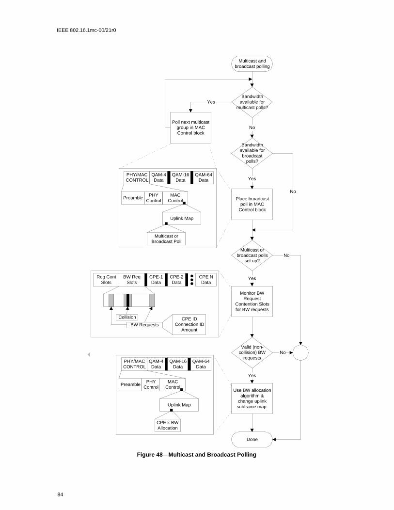
IEEE 802.16.1mc-00/21r0
PRELIM
INARY S
UBMIT
TAL
Figure 48—Multicast and Broadcast Polling
Multicast andbroadcast polling
Bandwidthavailable for
multicast polls?
Bandwidthavailable forbroadcast
polls?
Poll next multicastgroup in MACControl block
Place broadcastpoll in MAC
Control block
Multicast orbroadcast polls
set up?
Monitor BWRequest
Contention Slotsfor BW requests
Valid (non-collision) BW
requests
Use BW allocationalgorithm &
change uplinksubframe map.
Done
Yes
No
Yes
No
Yes
Yes
No
No
PHY/MACCONTROL
QAM-64Data
QAM-16Data
QAM-4Data
PreambleMAC
ControlPHY
Control
Uplink Map
CPE k BWAllocation
PHY/MACCONTROL
QAM-64Data
QAM-16Data
QAM-4Data
PreambleMAC
ControlPHY
Control
Uplink Map
CPE-2Data
Reg ContSlots
CPE NData
CPE-1Data
BW Requests
BW ReqSlots
Collision CPE IDConnection ID
Amount
Multicast orBroadcast Poll
84

IEEE 802.16.1mc-00/21r0
PRELIM
INARY S
UBMIT
TAL
6.7.1.3 Broadcast
6.7.2 Poll-Me Bit
Currently active CPEs may set the poll me bit (bit PM in the MAC header) or the priority poll me bit (bitPPM in the MAC header) in a MAC packet to indicate to the BS that they need polled to negotiate a band-width change. To reduce the bandwidth requirements of individual polling, active CPEs will be individuallypolled only if one of these bits is set. Once the BS detects this request for polling, the process for individualpolling is used to satisfy the request. The procedure by which a CPE stimulates the BS to poll it is shown inFigure TBD. To minimize the risk of the BS missing the poll me bit, the CPE may set the bit in all MACheaders in the frame.
85

IEEE 802.16.1mc-00/21r0
PRELIM
INARY S
UBMIT
TAL
6.7.3 Piggy-Back and Bandwidth Requests
Figure 49—Poll Me Bit Usage
Poll Me Bit Usage
Piggybackingexhausted?
Attemptpiggybacking first
AnyConnection orBW needs?
Connection = firstconnection
Set PM=1 inMAC header
Connection =Next connection
Lastconnection?
Done
Yes
No
Yes
No
Yes
No
86

IEEE 802.16.1mc-00/21r0
PRELIM
INARY S
UBMIT
TAL
6.8 Network Entry and Initialization
The procedure for initialization of a CPE modem MUST be as shown in Figure TBD. This figure shows the
overall flow between the stages of initialization in a CPE. This shows no error paths, and is simply to pro-
vide an overview of the process. The more detailed finite state machine representations of the individual sec-
tions (including error paths) are shown in the subsequent figures. Timeout values are defined in TBD.
The procedure can be divided into the following phases:
a) Scan for downstream channel and establish synchronization with the BS.b) Obtain transmit parameters (from UCD message)c) Perform rangingd) Establish IP connectivity e) Establish time of dayf) Transfer operational parametersg) Perform registrationh) Privacy initialization (if provisioned to utilize Privacy capabilities)
Each CPE contains the following information when shipped from the manufacturer:
a) A unique IEEE 802 48-bit MAC address which is assigned during the manufacturing process. Thisis used to identify the modem to the various provisioning servers during initialization.
b) Security information as defined in Section 7 (e.g., X.509 certificate) used to authenticate the CPE tothe security server and authenticate the responses from the security and provisioning servers.
87

IEEE 802.16.1mc-00/21r0
PRELIM
INARY S
UBMIT
TAL
6.8.1 Scanning and Synchronization to Downstream
On initialization or after signal loss, the CPE modem MUST acquire a downstream channel. The CPEMUST have non-volatile storage in which the last operational parameters are stored and MUST first try tore-acquire this downstream channel. If this fails, it MUST begin to continuously scan the possible channelsof the downstream frequency band of operation until it finds a valid downstream signal.
Figure 50— CPE Initialization Overview
Scan forDownstream
Channel
BaselinePrivacy
Initialization
Operational
*1 *1:Baseline Privacy
enabled
Baseline Privacy
Initialized
DownstreamSync
Established
ObtainUpstream
Parameters
Ranging &Automatic
Adjustments
Upstream Parameters
Aquired
Ranging &Auto AdjComplete
EstablishIP
Connectivety
IPComplete
EstablishTime of
Day
Time of Day Established
TransferOperationalParameters
Transfer Complete
Registerwith
CMTS
Registration Complete
No
Yes
88

IEEE 802.16.1mc-00/21r0
for itsmes-
r mes-m chan-and are
am chan-
chan-ning to
arame- chan- It thenssage.smit-
ssful, are no
.
PRELIM
INARY S
UBMIT
TAL
A downstream signal is considered to be valid when the CPE has achieved the following steps:
a) synchronization of the modulation symbol timingb) synchronization of the convolutional decoder if presentc) synchronization of the FEC framingd) synchronization of the MPEG packetizatione) recognition of SYNC downstream MAC messages
This implies that it has locked onto the correct frequency, equalized the downstream channel, recovered anyPMD sublayer framing and the FEC is operational (refer to Section TBD). At this point, a valid bit stream isbeing sent to the transmission convergence sublayer. The transmission convergence sublayer performs itsown synchronization. On detecting the well-known BWA PID, along with a payload unit start indicator per[ITU-T H.222.0], it delivers the MAC frame to the MAC sublayer.
The MAC sublayer MUST now search for the Timing Synchronization (SYNC) MAC management mes-sages. The CPE achieves MAC synchronization once it has received at least two SYNC messages for thesame Upstream Channel ID and has verified that its clock tolerances are within specified limits.
A CPE remains in “SYNC” as long as it continues to successfully receive the SYNC messagesUpstream Channel ID. If the Lost SYNC Interval (refer to TBD) has elapsed without a valid SYNC sage, a CPE MUST NOT use the upstream and MUST try to re-establish synchronization again.
6.8.2 Obtain Downstream Parameters
6.8.3 Obtain Upstream Parameters
Refer to Figure TBD. After synchronization, the CPE MUST wait for an upstream channel descriptosage (UCD) from the BS in order to retrieve a set of transmission parameters for a possible upstreanel. These messages are transmitted periodically from the BS for all available upstream channels addressed to the MAC broadcast address. The CPE MUST determine whether it can use the upstrenel from the channel description parameters.
The CPE MUST collect all UCDs which are different in their channel ID field to build a set of usable nel IDs. If no channel can be found after a suitable timeout period, then the CPE MUST continue scanfind another downstream channel.
The CPE MUST determine whether it can use the upstream channel from the channel description pters. If the channel is not suitable, then the CPE MUST try the next channel ID until it finds a usablenel. If the channel is suitable, the CPE MUST extract the parameters for this upstream from the UCD.MUST wait for the next SYNC message and extract the upstream mini-slot timestamp from this meThe CPE then MUST wait for a bandwidth allocation map for the selected channel. It MAY begin tranting upstream in accordance with the MAC operation and the bandwidth allocation mechanism.
The CPE MUST perform initial ranging at least once per Figure TBD. If initial ranging is not succethen the next channel ID is selected, and the procedure restarted from UCD extraction. When theremore channel IDs to try, then the CPE MUST continue scanning to find another downstream channel
89

IEEE 802.16.1mc-00/21r0
PRELIM
INARY S
UBMIT
TAL
Figure 51— Obtaining Upstream Parameters
Extract upstreamminislot timing
Good upstreamdescriptor
Wait for SYNC
SYNC
Wait for mapfor this channel
Map for selectedchannel
InitialRanging
InitialRanging
Successful?
StationMaintenance
TimeoutT1
Scanning
Collect UCDMessages
Wait for usableUCD
Build channel list
Select firstchannel
End ofchannel
list?
Select nextchannel
Yes
No
Yes
90
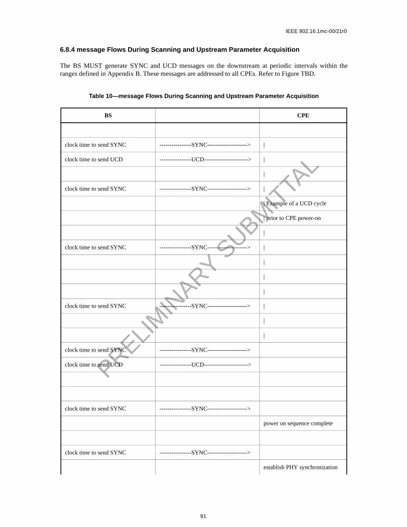
IEEE 802.16.1mc-00/21r0
PRELIM
INARY S
UBMIT
TAL
6.8.4 message Flows During Scanning and Upstream Parameter Acquisition
The BS MUST generate SYNC and UCD messages on the downstream at periodic intervals within theranges defined in Appendix B. These messages are addressed to all CPEs. Refer to Figure TBD.
Table 10—message Flows During Scanning and Upstream Parameter Acquisition
BS CPE
clock time to send SYNC ----------------SYNC--------------------> |
clock time to send UCD ----------------UCD----------------------> |
|
clock time to send SYNC ----------------SYNC--------------------> |
| Example of a UCD cycle
| prior to CPE power-on
|
clock time to send SYNC ----------------SYNC--------------------> |
|
|
|
clock time to send SYNC ----------------SYNC--------------------> |
|
|
clock time to send SYNC ----------------SYNC-------------------->
clock time to send UCD ----------------UCD---------------------->
clock time to send SYNC ----------------SYNC-------------------->
power on sequence complete
clock time to send SYNC ----------------SYNC-------------------->
establish PHY synchronization
91

IEEE 802.16.1mc-00/21r0
ions aretively PMD
teristicsmodem Sec-ion in
tenance
he CPExt tode the
nging
PRELIM
INARY S
UBMIT
TAL
6.8.5 Initial Ranging and Automatic Adjustments
Ranging is the process of acquiring the correct timing offset such that the CPE modem’s transmissaligned to the correct mini-slot boundary. The timing delays through the PHY layer MUST be relaconstant. Any variation in the PHY delays MUST be accounted for in the guard time of the upstreamoverhead.
First, a CPE modem MUST synchronize to the downstream and learn the upstream channel characthrough the Upstream Channel Descriptor MAC management message. At this point, the CPE MUST scan the Bandwidth Allocation MAP message to find an Initial Maintenance Region. Refer totion TBD. The BS MUST make an Initial Maintenance region large enough to account for the variatdelays between any two CPEs.
The CPE modem MUST put together a Ranging Request message to be sent in an Initial Mainregion. The SID field MUST be set to the non-initialized CPE value (zero).
Ranging adjusts each CPE’s timing offset such that it appears to be located right next to the BS. TMUST set its initial timing offset to the amount of internal fixed delay equivalent to putting this CPE nethe BS. This amount includes delays introduced through a particular implementation, and MUST includownstream PHY interleaving latency.
When the Initial Maintenance transmit opportunity occurs, the CPE modem MUST send the RaRequest message. Thus, the CPE modem sends the message as if it was physically right at the BS.
& wait for UCD
clock time to send SYNC ----------------SYNC-------------------->
clock time to send SYNC ----------------SYNC-------------------->
clock time to send UCD ----------------UCD---------------------->
obtain parameters for this upstream channel to use for ini-tialization
clock time to send SYNC ----------------SYNC-------------------->
extract slot info for upstream & wait for transmit opportunity to perform ranging
clock time to send SYNC ----------------SYNC-------------------->
clock time to send MAP ----------------MAP---------------------->
start ranging process
Table 10—message Flows During Scanning and Upstream Parameter Acquisition
BS CPE
92

IEEE 802.16.1mc-00/21r0
PRELIM
INARY S
UBMIT
TAL
Once the BS has successfully received the Ranging Request message, it MUST return a Ranging Responsemessage addressed to the individual CPE modem. Within the Ranging Response message MUST be a tem-porary SID assigned to this CPE modem until it has completed the registration process. The message MUSTalso contain information on RF power level adjustment and offset frequency adjustment as well as any tim-ing offset corrections.
The CPE modem MUST now wait for an individual Station Maintenance region assigned to its temporarySID. It MUST now transmit a Ranging Request message at this time using the temporary SID along withany power level and timing offset corrections.
The BS MUST return another Ranging Response message to the CPE modem with any additional fine tun-ing required. The ranging request/response steps MUST be repeated until the response contains a RangingSuccessful notification or the BS aborts ranging. Once successfully ranged, the CPE modem MUST joinnormal data traffic in the upstream. In particular, state machines and the applicability of retry counts andtimer values for the ranging process are defined in Section TBD.
Note: The burst type to use for any transmission is defined by the Interval Usage Code (IUC). Each IUC ismapped to a burst type in the UCD message.
The message sequence chart and the finite state machines on the following pages define the ranging andadjustment process which MUST be followed by compliant CPEs and BS. Refer to Figure TBD throughFigure TBD
Table 11—Ranging and Automatic Adjustments Procedure
BS CPE
[time to send the Initial Mainte-nance opportunity]
send map containing Initial Main-tenance information element with a broadcast/multicast Service ID
-----------MAP------------>
<---------RNG-REQ------- transmit ranging packet in con-tention mode
with Service ID parameter = 0
[receive recognizable ranging packet]
allocate temporary Service ID
93

IEEE 802.16.1mc-00/21r0
PRELIM
INARY S
UBMIT
TAL
Note: The BS MUST allow the CPE sufficient time to have processed the previous RNG-RSP (i.e., to modify thetransmitter parameters) before sending the CPE a specific ranging opportunity. This is defined as CPE RangingResponse Time in TBD
send ranging response ----------RNG-RSP------->
add temporary Service ID to poll list
store temporary Service ID & adjust other parameters
[time to send the next map]
send map with Station Mainte-nance information element to modem using temporary SID
-----------MAP------------> recognize own temporary Ser-vice ID in map
<---------RNG-REQ------- reply to Station Maintenance opportunity poll
send ranging response ----------RNG-RSP------->
adjust local parameters
[time to send an Initial Mainte-nance opportunity] send map con-taining Initial Maintenance information element with a broad-cast/multicast Service ID
send periodic transmit opportu-nity to broadcast address
------------MAP----------->
Table 11—Ranging and Automatic Adjustments Procedure
BS CPE
94

IEEE 802.16.1mc-00/21r0
PRELIM
INARY S
UBMIT
TAL
Figure 52—Initial Ranging - CPE
Wait for broadcastmaintenanceopportunity
Wait for unicastmaintenanceopportunity
Wait forbroadcast ranging
opportunity
Error
Re-initialize MAC
Wait forRNG-RSP
Error
Re-initialize MAC
Adjust
local power
Randombackoff (Note)
Adjust localparameters per
RNG-RSP
Timeout T2
SendRNG-REQ
Timeout T3
RNG-RSP
Y
N
Map withmainten-ance
opportunity
Retriesexhausted
?
Note: Timeout T3 may occur because the RNG-REQs from multiple modemscollided. To avoid theses modems repeating the loop in lockstep, a random backoffis required. This is a backoff over the ranging window specified in the MAP. T3timeouts can also occur during multi-channel operation. On a system with multipleupstream channels, the CM MUST attempt initial ranging on every suitableupstream channel before moving to the next available downstream channel.
95

IEEE 802.16.1mc-00/21r0
PRELIM
INARY S
UBMIT
TAL
1) Ranging Request is within the tolerance of the BS.
Figure 53—Initial Ranging - CPE (continued)
Timeout T4Map withMaintenance
opportunity
Error:Re-initialize MAC
SendRNG-REQ
Wait forRNG-RSP
Timeout T3 RNG-RSP
Adjust localparameters per
RNG-RSP
Success set fromCMTS?(Note 1)
Enable datatransfer
Establish IP layer
Yes
Abort Ranging setfrom CMTS?
No
Retries Exhausted?
No
Error:Re-initialize MAC
Yes
Adjust localpower
No
Error:Re-initialize MAC
Yes
Wait forStation Maintenance
opportunity
Wait forStation Maintenance
opportunity
96

IEEE 802.16.1mc-00/21r0
PRELIM
INARY S
UBMIT
TAL
Figure 54—Initial Ranging - BS
Yes
No
Wait forrecognizableRNG-REQ
RNG-REQ
Assign temporarySID
Add CM to polllist for future
maps
Send RNG-RSP(continue)
Reset retry countin poll list for this
CM
No
Wait for polledRNG-REQ
RNG-REQ
Good Enough?(Note 1)
No
RNG-REQ not
received
SendRNG-RSP(success)
Yes
No
Remove CM frompoll list
Done
SendRNG-RSP(continue)
SendRNG-RSP
(abort)
Yes
Wait for polledRNG-REQ
Remove CM frompoll list
Wait forrecognizableRNG-REQ
Yes
Retries Exhausted?
Retries Exhausted?
SID assigned tothis CM already?
Map will be sent per allocationalgorithm and pending tillcomplete. (Note 2)
Start T9
97

IEEE 802.16.1mc-00/21r0
testuntil
eipt) ofection
non-
ount in
e BS)
annel
events accurate
Figuree. The3] and
PRELIM
INARY S
UBMIT
TAL
1) Means ranging is within the tolerable limits of the BS.2) RNG-REQ pending-till-complete was nonzero, the BS SHOULD hold off the station mainte-
nance opportunity accordingly unless needed, for example, to adjust the CPE’s power level. Ifopportunities are offered prior to the pending-till-complete expiry, the “good-enough” which follows receipt of a RNG-RSP MUST NOT judge the CPE's transmit equalization pending-till-complete expires.
6.8.6 Ranging Parameter Adjustment
Adjustment of local parameters (e.g., transmit power) in a CPE as a result of the receipt (or non-recan RNG-RSP is considered to be implementation-dependent with the following restrictions (refer to STBD):
All parameters MUST be within the approved range at all times
a) Power adjustment MUST start from the minimum value unless a valid power is available fromvolatile storage, in which case this MUST be used as a starting point.
b) Power adjustment MUST be capable of being reduced or increased by the specified amresponse to RNG-RSP messages.
c) If, during initialization, power is increased to the maximum value (without a response from thit MUST wrap back to the minimum.
For multi-channel support, the CPE MUST attempt initial ranging on every suitable upstream chbefore moving to the next available downstream channel.
6.8.7 Initial Connection Establishment
6.8.7.1 Establish IP Connectivity
At this point, the CPE MUST invoke DHCP mechanisms [RFC-2131] in order to obtain an IP address andany other parameters needed to establish IP connectivity (refer to TBD). The DHCP response MUST containthe name of a file which contains further configuration parameters. Refer to Figure 5-64
6.8.7.2 Establish Time of Day
The CPE and BS need to have the current date and time. This is required for time-stamping loggedwhich can be retrieved by the management system. This need not be authenticated and need only beto the nearest second.
The protocol by which the time of day MUST be retrieved is defined in [RFC-868]. Refer to Figure TBD.The request and response MUST be transferred using UDP. The time retrieved from the server (UTC)MUST be combined with the time offset received from the DHCP response to create the current local time
Successfully acquiring the Time of Day is not mandatory for a successful registration, but is necessary foron-going operation. The specific timeout for Time of Day Requests is implementation dependent. However,the CPE MUST NOT exceed more than 3 Time of Day requests in any 5 minute period.
6.8.8 Transfer Operational Parameters
After DHCP is successful, the modem MUST download the parameter file using TFTP, as shown in TBD. The TFTP configuration parameter server is specified by the “siaddr” field of the DHCP responsCPE MUST use an adaptive timeout for TFTP based on binary exponential backoff. Refer to [RFC112[RFC2349].
98

IEEE 802.16.1mc-00/21r0
PRELIM
INARY S
UBMIT
TAL
The parameter fields required in the DHCP response and the format and content of the configuration fileMUST be as defined in Section TBD. Note that these fields are the minimum required for interoperability.
If a modem downloads a configuration file containing an upstream channel and/or downstream frequencydifferent from what the modem is currently using, the modem MUST NOT send a Registration Requestmessage to the BS. The modem MUST redo initial ranging using the configured upstream channel and/ordownstream frequency per Section TBD.
6.8.8.1 Registration
A CPE MUST be authorized to forward traffic into the network once it is initialized and configured. TheCPE is authorized to forward traffic into the network via registration. To register with a BS, the CPE MUST
Table 12—Establishing IP Connectivity
CPE DHCP
send DHCP request to broad-cast address
----------------DHCP discover------------>
check CPE MAC address & respond
<--------------DHCP offer -----------------
choose server
----------------DHCP request-------------->
process request
<--------------DHCP response--------------
set up IP parameters from DHCP response
Table 13—Establishing Time of Day
CPE Time Server
send request to time server
----------------time of day request------------>
process request
<--------------time of day response--------------
set up / correct time of day from response
99

IEEE 802.16.1mc-00/21r0
the config-
PRELIM
INARY S
UBMIT
TAL
forward its configured class of service and any other operational parameters in the configuration file (refer toSection TBD) to the BS as part of a Registration Request. Figure TBD shows the procedure that MUST befollowed by the CPE.
The configuration parameters downloaded to the CPE MUST include a network access control object (seeSection TBD). If this is set to “no forwarding,” the CPE MUST NOT forward data from attached CPE tonetwork, yet the CPE MUST respond to network management requests. This allows the CPE to beured in a mode in which it is manageable but will not forward data.
100

IEEE 802.16.1mc-00/21r0
PRELIM
INARY S
UBMIT
TAL
Figure 55—Registration — CPE
Wait for Time ofDay Response
AcquireOperationalParameters
Wait for Reg-Rsp
RequestConfig File
Send Reg-Req
Time of DayRequest
Time of DayResponse
Timeout
Wait forSuccessful TFTP
Config FileReceived
Timeout
Mandatoryitems present?
CM MIC valid?
Yes
Yes
Time of Day retries areasynchronous with registration
IncrementRetry Counter
Retriesexceeded?
Scan forDownstream
Channel
No
Yes
101

IEEE 802.16.1mc-00/21r0
PRELIM
INARY S
UBMIT
TAL
Once the CPE has sent a Registration Request to the BS it MUST wait for a Registration Response to autho-rize it to forward traffic to the network. Figure 56 shows the waiting procedure that MUST be followed bythe CPE.
The BS MUST perform the following operations to confirm the CPE authorization (refer to Figure TBD):
a) Calculate a MIC per TBD and compare it to the BS MIC included in the Registration Request. If theMIC is invalid, the BS MUST respond with an Authorization Failure.
b) If present, check the TFTP Server Timestamp field. If the BS detects that the time is different fromits local time by more than CPE Configuration Processing Time (refer to TBD), the BS MUST indi-cate authentication failure in the REG-RSP. The BS SHOULD also make a log entry stating the CPEMAC address from the message.
c) If present, check the TFTP Server Provisioned Modem Address field. If the Provisioned ModemAddress does not match the requesting modem’s actual address, the BS MUST indicate authentica-tion failure in the REG-RSP. The BS SHOULD also make a log entry stating the CPE MAC addressfrom the message.
Figure 56—Wait for Registration Response — CPE
Wait for Reg-Rsp
SendReg-Req
Reg-RspTimeout T6
Response=ok?
Operational
ImplementationDependent
Retriesexhausted?
Error: Re-initializeMAC
No
Yes
Setup Service Flows &Activate Operational
Parameters
Yes
No
Wait for Reg-Rsp SendReg-Ack
Reg-Rsp
102

IEEE 802.16.1mc-00/21r0
tration
PRELIM
INARY S
UBMIT
TAL
d) If the Registration Request contains Service Flow encodings, verify the availability of the Quality ofService requested in the provisioned Service Flow(s). If unable to provide the Service Flow(s), theBS MUST respond with a Class of Service Failure and the appropriate Service Flow Response(s).
e) Verify the availability of any Modem Capabilities requested. If unable or unwilling to provide theModem Capability requested, the BS MUST turn that Modem Capability ‘off’ (refer to TBD).
f) Assign a Service Flow ID for each class of service supported.g) Reply to the modem in a Registration Response.h) If the Registration Request contains Service Flow encodings, the BS MUST wait for a Regis
Acknowedgment as shown in Figure TBD.
If timer T9 expires, the BS MUST both de-assign the temporary SID from that CPE and make some provi-sion for aging out that SID.
103

IEEE 802.16.1mc-00/21r0
PRELIM
INARY S
UBMIT
TAL
Figure 57—Registration — BS
Waiting for Reg-Req
Reg-Req
CMTS MICValid?
Calculate MICover Reg-Req
Wait for Reg-Req
Send Reg-Rsp withResponse =
Authentication Failure
TFTP Server IP and/or Timestamp Valid?
Yes
No
Send Reg-Rsp withResponse =
Authentication Failure &Should Log Failure
No
Can the requestedservice(s) ever be
supported?
Send Reg-Rsp withResponse = Class of
Service Failure & ServiceNot Available=Reason
Permanent
No
Can the requestedservice(s) currently
be supported?
Yes
Send Reg-Rsp withResponse = Class of
Service Failure & ServiceNot Available=Reason
Temporary
No
Send Reg-Rsp withResponse = ok
Waiting for Reg-Ack
Set modemcapabilities
supported inRegRsp
Yes
CreateRequested
Services
Stop T9
104

IEEE 802.16.1mc-00/21r0
PRELIM
INARY S
UBMIT
TAL
6.8.8.2 Baseline Privacy Initialization
Following registration, if the CPE is provisioned to run Baseline Privacy, the CPE MUST initialize BaselinePrivacy operations, as described in [DOCSIS8]. A CPE is provisioned to run Baseline Privacy if its configu-ration file includes a Baseline Privacy Configuration Setting (section C.3.2) and if the Privacy Enableparameter (section TBD) is set to enable.
6.8.8.3 Service IDs During CPE Initialization
After completion of the Registration process, the CPE will have been assigned Service Flow IDs (SFIDs) tomatch its provisioning. However, the CPE must complete a number of protocol transactions prior to thattime (e.g., Ranging, DHCP, etc.), and requires a temporary Service ID in order to complete those steps.
On reception of an Initial Ranging Request, the BS MUST allocate a temporary SID and assign it to the CPEfor initialization use. The BS MAY monitor use of this SID and restrict traffic to that needed for initializa-tion. It MUST inform the CPE of this assignment in the Ranging Response.
On receiving a Ranging Response addressed to it, the CPE MUST use the assigned temporary SID for fur-ther initialization transmission requests until the Registration Response is received.
On receiving a Ranging Response instruction to move to a new downstream frequency and/or upstreamchannel ID, the CPE MUST consider any previously assigned temporary SID to be deassigned, and mustobtain a new temporary SID via initial ranging.
Figure 58—Registration Acknowledgment— BS
Waiting for Reg-Ack
Reg-Ack
RetriesExhausted?
DestroyServices
Wait for Reg-Ack
Waiting for Reg-Req
Timeout T7
Yes
Waiting for Reg-Req
Send Reg-Rspwith Response
= OK
No
105

IEEE 802.16.1mc-00/21r0
riodic
PRELIM
INARY S
UBMIT
TAL
It is possible that the Ranging Response may be lost after transmission by the BS. The CPE MUST recoverby timing out and re-issuing its Initial Ranging Request. Since the CPE is uniquely identified by the sourceMAC address in the Ranging Request, the BS MAY immediately re-use the temporary SID previouslyassigned. If the BS assigns a new temporary SID, it MUST make some provision for aging out the old SIDthat went unused (see Section TBD).
When assigning provisioned SFIDs on receiving a Registration Request, the BS may re-use the temporarySID, assigning it to one of the Service Flows requested. If so, it MUST continue to allow initialization mes-sages on that SID, since the Registration Response could be lost in transit. If the BS assigns all-new SIDs forclass-of-service provisioning, it MUST age out the temporary SID. The aging-out MUST allow sufficienttime to complete the registration process in case the Registration Response is lost in transit.
6.8.8.4 Multiple-Channel Support
In the event that more than one downstream signal is present in the system, the CPE MUST operate usingthe first valid downstream signal that it encounters when scanning. It will be instructed via the parameters inthe configuration file to shift operation to different downstream and/or upstream frequencies if necessary.
Both upstream and downstream channels MUST be identified where required in MAC management mes-sages using channel identifiers.
6.9 Ranging
The BS MUST provide each CPE a Periodic Ranging opportunity at least once every T4 seconds. The BSMUST send out Periodic Ranging opportunities at an interval sufficiently shorter than T4 that a MAP couldbe missed without the CPE timing out. The size of this “subinterval” is BS dependent.
The CPE MUST reinitialize its MAC layer after T4 seconds have elapsed without receiving a PeRanging opportunity.
Remote RF signal level adjustment at the CPE is performed through a periodic maintenance function usingthe RNG-REQ and RNG-RSP MAC messages. This is similar to initial ranging and is shown in Figure TBDand Figure TBD. On receiving a RNG-RSP, the CPE MUST NOT transmit until the RF signal has beenadjusted in accordance with the RNG-RSP and has stabilized.
106

IEEE 802.16.1mc-00/21r0
PRELIM
INARY S
UBMIT
TAL
Figure 59—Periodic Ranging - BS
107

IEEE 802.16.1mc-00/21r0
PRELIM
INARY S
UBMIT
TAL
6.9.0.1 Downstream Modulation Management
The downstream modulation format (QPSK, 16-QAM or 64-QAM) is determined by the BS according tothe signal quality of the signal that is received by each CPE. To reduce the volume of upstream straffic, theCPE monitors the carrier to noise and interference ratio (CNIR), and compares the averaged value againstthe allowed region of operation. This region is bounded by threshold levels. If the received CNIR goes out-side of the allowed operating region, the CPE requests a change to a new modulation format using the RNG-REQ message. The BS acknowledges the reciept of the RNG-REQ message using the RNG-RSP message.The RNG-RSP message contains the new CPE operating modulation format, which can be either the sameof different from the existing format.
The CPE applies an algorithm to determine its maximum operating modulation type in accordance with the16 and 64-QAM Threshold parameters as established in the RNG-RSP message. The Threshold Deltaparameter MUST be applied to the two threshold points in accordance with Figure 61. The Threshold Deltaprovides a hysterisis around which the CPE applies the thresholds.
Figure 60—Periodic Ranging - CPE
SendRNG-REQ
Unicast maintenance opportunity
RNG-RSP
Operational
Error:Re-initialize MAC
Abort rangingfrom CMTS?
Timeout T4
IncrementRNG-REQ
Retry Counter
Timeout T3
RNG-REQretries exceeded?
YesYes
Adjust localparameters per
RNG-RSP
Reset RNG-REQRetry Counter;Clear T3 Timer
StartT3 Timer
StartT4 Timer
No
T3 Timerstarted?
No
Yes
Success or Continue
108

IEEE 802.16.1mc-00/21r0
PRELIM
INARY S
UBMIT
TAL
Table 14—Downstream Modulation Change Initiated from CPE
BS CPE
DS Modulation Requires Mod-ification
Receive RNG-REQ <--------- RNG-REQ ---------- Send RNG-REQ
Determine modulation type that is now appropriate
Modify modulation type within provisioned limits established for CPE
Send RNG-RSP ---------- RNG-RSP ---------> Receive RNG-RSP
Begin using new modulation type for the CPE
Figure 61—Modulation Threshold Usage
40
30
20
10
0
C/(
N+
I)
(dB
)
64-QAM Threshold + Threshold Delta
64-QAM Threshold - Threshold Delta
16-QAM Threshold + Threshold Delta
16-QAM Threshold - Threshold Delta
64-QAM Region
16-QAM Region
QPSK Region
109

IEEE 802.16.1mc-00/21r0
PRELIM
INARY S
UBMIT
TAL
110

IEEE 802.16.1mc-00/21r0
PRELIM
INARY S
UBMIT
TAL
6.10 Quality of Service
This standard defines several Quality of Service (QoS) related concepts. These include:
a) Service Flow QoS Schedulingb) Dynamic Service Establishmentc) Two-Phase Activation Model
6.10.1 Theory of Operation
The various BWA protocol mechanisms described in this document can be used to support Quality of Ser-vice (QoS) for both upstream and downstream traffic through the CPE and the BS. This section provides anoverview of the QoS protocol mechanisms and their part in providing end-to-end QoS.
The requirements for Quality of Service include:
a) A configuration and registration function for pre-configuring CPE-based QoS Service Flows andtraffic parameters.
b) A signaling function for dynamically establishing QoS-enabled Service Flows and traffic parametersc) A traffic-shaping and traffic-policing function for Service Flow-based traffic management, per-
formed on traffic arriving from the upper layer service interface and outbound to the RF. d) Utilization of MAC scheduling and traffic parameters for upstream Service Flows.e) Utilization of QoS traffic parameters for downstream Service Flows.f) Grouping of Service Flow properties into named Service Classes, so upper layer entities and exter-
nal applications (at both the CPE and BS) can request Service Flows with desired QoS parameters ina globally consistent way.
The principal mechanism for providing QoS is to associate packets traversing the RF MAC interface into aService Flow as identified by the Connection ID. A Service Flow is a unidirectional flow of packets that isprovided a particular Quality of Service. The CPE and BS provide this QoS by shaping, policing, and prior-itizing traffic according to the QoS Parameter Set defined for the Service Flow.
The primary purpose of the Quality of Service features defined here is to define transmission ordering andscheduling on the air interface. However, these features often need to work in conjunction with mechanismsbeyond the air interface in order to provide end-to-end QoS or to police the behavior of CPE modems.
Service Flows exist in both the upstream and downstream direction, and MAY exist without actually beingactivated to carry traffic. Service Flows have a 32-bit Service Flow Identifier (SFID) assigned by the BS.All Service Flows have an SFID; active upstream Service Flows also have a 16-bit Connection Identifier(CID).
At least two Service Flows must be defined in each configuration file: one for upstream and one for down-stream service. The first upstream Service Flow describes the Primary Upstream Service Flow, and is thedefault Service Flow used for otherwise unclassified traffic and all MAC Messages. The first downstreamService Flow describes service to the Primary Downstream Service Flow. Additional Service Flowsdefined in the Configuration file create Service Flows that are provided QoS services.
6.10.2 Service Flows
A Service Flow is a MAC-layer transport service that provides unidirectional transport of packets either toupstream packets transmitted by the CPE or to downstream packets transmitted by the BS1. A Service Flowis characterized by a set of QoS Parameters such as latency, jitter, and throughput assurances. In order tostandardize operation between the CPE and BS, these attributes include details of how the CPE requestsupstream minislots and the expected behavior of the BS upstream scheduler.
111

IEEE 802.16.1mc-00/21r0
velope”t.
3. Thet ofuthori-
mSete
A and B
PRELIM
INARY S
UBMIT
TAL
A Service Flow is partially characterized by the following attributes2:
a) ServiceFlowID: exists for all service flowsb) Connection ID: only exists for admitted or active service flowsc) ProvisionedQosParamSet: defines a set of QoS Parameters which appears in the configuration file
and is presented during registration. This MAY define the initial limit for authorizations allowed bythe authorization module. The ProvisionedQosParamSet is defined once when the Service Flow iscreated via registration.3
d) AdmittedQosParamSet: defines a set of QoS parameters for which the BS (and possibly the CPE)are reserving resources. The principal resource to be reserved is bandwidth, but this also includesany other memory or time-based resource required to subsequently activate the flow.
e) ActiveQosParamSet: defines set of QoS parameters defining the service actually being provided tothe Service Flow. Only an Active Service Flow may forward packets.
f) A Service Flow exists when the BS assigns a Service Flow ID (SFID) to it. The SFID serves as theprincipal identifier in the CPE and BS for the Service Flow. A Service Flow which exists has at leastan SFID, and an associated Direction.
g) The Authorization Module is a logical function within the BS that approves or denies every changeto QoS Parameters and Classifiers associated with a Service Flow. As such it defines an “enthat limits the possible values of the AdmittedQoSParameterSet and ActiveQoSParameterSe
The relationship between the QoS Parameter Sets is as shown in Figure 62 and Figure 6ActiveQoSParameterSet is always a subset4 of the AdmittedQoSParameterSet which is always a subsethe authorized “envelope.” In the dynamic authorization model, this envelope is determined by the A
1A Service Flow, as defined here, has no direct relationship to the concept of a “flow” as defined by the IETF’s Integrated Services (int-serv) Working Group [RFC-2212]. An intserv flow is a collection of packets sharing transport-layer endpoints. Multiple intservflowscan be served by a single Service Flow.2Some attributes are derived from the above attribute list. The Service Class Name is an attribute of the ProvisionedQoSPara. Theactivation state of the Service Flow is determined by the ActiveQoSParamSet. If the ActiveQoSParamSet is null then the servicflow isinactive.3The ProvisionedQoSParamSet is null when a flow is created dynamically.4To say that QoS Parameter Set A is a subset of QoS Parameter Set B the following MUST be true for all QoS Parameters in:if (a smaller QoS parameter value indicates less resources, e.g. Maximum Traffic Rate)A is a subset of B if the parameter in A less than or equal to the same parameter in Bif (a larger QoS parameter value indicates less resources, e.g. Tolerated Grant Jitter)A is a subset of B if the parameter in A is greater than or equal to the same parameter in Bif (the QoS parameter specifies a periodic interval, e.g. Nominal Grant Interval), A is a subset of B if the parameter in A is an integer multiple of the same parameter in Bif (the QoS parameter is not quantitative, e.g. Service Flow Scheduling Type)A is a subset of B if the parameter in A is equal to the same parameter in B
112

IEEE 802.16.1mc-00/21r0
PRELIM
INARY S
UBMIT
TAL
zation Module (labeled as the AuthorizedQoSParameterSet). In the provisioned authorization model, thisenvelope is determined by the ProvisionedQoSParameterSet.
Figure 62—Provisioned Authorization Model “Envelopes”
AuthQoSParamSet = ProvisionedQoSParamSet(SFID)
AdmittedQoSParamSet(SFID & CID)
ActiveQoSParamSet(SFID & Active CID)
113

IEEE 802.16.1mc-00/21r0
PRELIM
INARY S
UBMIT
TAL
It is useful to think of three types of Service Flows:
a) Provisioned: this type of Service Flow is known via provisioning through the configuration file, itsAdmittedQoSParamSet and ActiveQoSParamSet are both null.
b) Admitted: this type of Service Flow has resources reserved by the BS for its AdmittedQoSParam-Set, but these parameters are not active (its ActiveQoSParamSet is null). Admitted Service Flowsmay have been provisioned or may have been signalled by some other mechanism.
c) Active: this type of Service Flow has resources committed by the BS for its QoS Parameter Set, (e.g.is actively sending MAPs containing unsolicited grants for a UGS-based service flow). ItsActiveQoSParamSet is non-null.
6.10.3 Object Model (FIX THIS SECTION)
The major objects of the architecture are represented by named rectangles in Figure 5-43. Each object has anumber of attributes; the attribute names which uniquely identify the object are underlined. Optionalattributes are denoted with brackets. The relationship between the number of objects is marked at each endof the association line between the objects. For example, a Service Flow may be associated with from 0 to65535 Classifiers, but a Classifier is associated with exactly one Service flow.
The Service Flow is the central concept of the MAC protocol. It is uniquely identified by a 32-bit ServiceFlow ID (SFID) assigned by the BS. Service Flows may be in either the upstream or downstream direction.Admitted Upstream Service Flows are assigned a 14-bit Service ID (SID).
Figure 63—Dynamic Authorization Model “Envelopes”
ProvisionedQoSParamSet(SFID)
AdmittedQoSParamSet(SFID & CID)
ActiveQoSParamSet(SFID & Active CID)
AuthQoSParamSet(BS only, not known by CPE)
114

IEEE 802.16.1mc-00/21r0
w QoSsubject to
pro-e; the
mple-g. Fornt Bsstime of
com-
exam-ervice
PRELIM
INARY S
UBMIT
TAL
Outgoing user data is submitted to the MSAP by an convergence sub-layer process for transmission on theMAC interface. The information delivered to the MSAP includes the Connection Identifier identfying theconnection across which the information is delivered. The Service Flow for the connection is mapped via theConnection ID (CID).
The Service Class is an optional object that may be implemented at the BS. It is referenced by an ASCIIname which is intended for provisioning purposes. A Service Class is defined in the BS to have a particularQoS Parameter Set. The QoS Parameter Sets of a Service Flow may contain a reference to the Service ClassName as a “macro” that selects all of the QoS parameters of the Service Class. The Service FloParameter Sets may augment and even override the QoS parameter settings of the Service Class, authorization by the BS.
6.10.4 Service Classes
The Service Class serves the following purposes:
1) It allows operators, who so wish, to move the burden of configuring service flows from thevisioning server to the BS. Operators provision the modems with the Service Class Namimplementation of the name is configured at the BS. This allows operators to modify the imentation of a given service to local circumstances without changing modem provisioninexample, some scheduling parameters may need to be tweaked differently for two differeto provide the same service. As another example, service profiles could be changed by day.
2) It allows BS vendors to provide class-based-queuing if they choose, where service flowspete within their class and classes compete with each other for bandwidth.
3) It allows higher-layer protocols to create a Service Flow by its Service Class Name. For ple, telephony signaling may direct the CPE to instantiate any available Provisioned SFlow of class “G711”.
Figure 64—Theory of Operation Object Model
Service Class
Service Class NameQoSParamSet
Service Flow
SFIDDirection[CID][ProvQosParamSet][AdmittedQoSParamSet][ActiveQosParamSet]
PDU
SFID[Service Class][CID][SFID]
0,1
N
115

IEEE 802.16.1mc-00/21r0
-
essfullyd Mes-, the BS
er Set ofparam-
eturnedstrative
ame isarameters exist-ition.
le. ThisQ Mes-an admis-e Flowd or acti-.
ores thesionedisionedeter Set.ate new
e initial
sages,ver mayts, and
requestset being
a CPE
PRELIM
INARY S
UBMIT
TAL
Note: The Service Class is optional: the flow scheduling specification may always be provided in full; a serviceflow may belong to no service class whatsoever. BS implementations MAY treat such “unclassed” flows differently from “classed” flows with equivalent parameters.
Any Service Flow MAY have its QoS Parameter Set specified in any of three ways:
a) By explicitly including all traffic parameters.b) By indirectly referring to a set of traffic parameters by specifying a Service Class Name.c) By specifying a Service Class Name along with modifying parameters.
The Service Class Name is “expanded” to its defined set of parameters at the time the BS succadmits the Service Flow. The Service Class expansion can be contained in the following BS-originatesages: Registration Response, DSA-REQ, DSC-REQ, DSA-RSP and DSC-RSP. In all of these casesMUST include a Service Flow Encoding that includes the Service Class Name and the QoS Parametthe Service Class. If a CPE-initiated request contained any supplemental or overriding Service Flow eters, a successful response MUST also include these parameters.
When a Service Class name is given in an admission or activation request, it is possible that the rQoS Parameter Set MAY change from activation to activation. This can happen because of adminichanges to the Service Class’ QoS Parameter Set at the BS. If the definition of a Service Class Nchanged at the BS (e.g. its associated QoS Parameter Set is modified), it has no effect on the QoS Pof existing Service Flows associated with that Service Class. A BS MAY initiate DSC transactions toing Service Flows which reference the Service Class Name to affect the changed Service Class defin
When a CPE uses the Service Class Name to specify the Admitted QoS Parameter Set, the expanded set ofTLV encodings of the Service Flow will be returned to the CPE in the response Message (REG-RSP, DSA-RSP, or DSC-RSP). Use of the Service Class Name later in the activation request MAY fail if the definitionof the Service Class Name has changed and the new required resources are not available. Thus, the CPESHOULD explicitly request the expanded set of TLVs from the response Message in its later activationrequest.
6.10.5 Authorization
Every change to the Service Flow QoS Parameters MUST be approved by an authorization moduincludes every REG-REQ or DSA-REQ Message to create a new Service Flow, and every DSC-REsage to change a QoS Parameter Set of an existing Service Flow. Such changes include requesting sion control decision (e.g. setting the AdmittedQoSParamSet) and requesting activation of a Servic(e.g. setting the ActiveQoSParameterSet). Reduction requests regarding the resources to be admittevated are also checked by the authorization module, as are requests to add or change the Classifiers
In the static authorization model, the authorization module receives all registration Messages, and stprovisioned status of all “deferred” Service Flows. Admission and activation requests for these proviservice flows will be permitted, as long as the Admitted QoS Parameter Set is a subset of the ProvQoS Parameter Set, and the Active QoS Parameter Set is a subset of the Admitted QoS ParamRequests to change the Provisioned QoS Parameter Set will be refused, as will requests to credynamic Service Flows. This defines a static system where all possible services are defined in thconfiguration of each CPE.
In the dynamic authorization model, the authorization module not only receives all registration Mesbut also communicates through a separate interface to an independent policy server. This policy serprovide to the authorization module advance notice of upcoming admission and activation requesspecifies the proper authorization action to be taken on those requests. Admission and activation from a CPE are then checked by the Authorization Module to ensure that the ActiveQoSParameterSrequested is a subset of the set provided by the policy server. Admission and activation requests from
116

IEEE 802.16.1mc-00/21r0
hat is,rovi-
assignsire an
a Pro-he CPEMUSTw, but
MAYted QoSServiceionedes, the
In theto-endre “acti-ompletesources
c) pre-
PRELIM
INARY S
UBMIT
TAL
that are signalled in advance by the external policy server are permitted. Admission and activation requestsfrom a CPE that are not pre-signalled by the external policy server may result in a real-time query to the pol-icy server, or may be refused.
During registration, the CPE MUST send to the BS the authenticated set of TLVs derived from its configura-tion file which defines the Provisioned QoS Parameter Set. Upon receipt and verification at the BS, these arehanded to the Authorization Module within the BS. The BS MUST be capable of caching the ProvisionedQoS Parameter Set, and MUST be able to use this information to authorize dynamic flows which are a sub-set of the Provisioned QoS Parameter Set. The BS SHOULD implement mechanisms for overriding thisautomated approval process (such as described in the dynamic authorization model). For example:
a) Deny all requests whether or not they have been pre-provisionedb) Define an internal table with a richer policy mechanism but seeded by the configuration file infor-
mationc) Refer all requests to an external policy server
6.10.6 Types of Service Flows
It useful to think about three basic types of Service Flows. This section describes these three types of ServiceFlows in more detail. However, it is important to note that there are more than just these three basic types.(Refer to Appendix C.2.2.5.1)
6.10.6.1 Provisioned Service Flows
A Service Flow may be Provisioned but not immediately activated (sometimes called “deferred”). Tthe description of any such service flow in the TFTP configuration file contains an attribute which psions but defers activation and admission (refer to Appendix C.2.2.5.1). During Registration, the BS a Service Flow ID for such a service flow but does not reserve resources. The BS MAY also requexchange with a policy module prior to admission.
As a result of external action beyond the scope of this specification , the CPE MAY choose to activatevisioned Service Flow by passing the Service Flow ID and the associated QoS Parameter Sets. TMUST also provide any applicable Classifiers. If authorized and resources are available, the BS respond by assigning a SID for the upstream Service Flow. The BS MAY deactivate the Service FloSHOULD NOT delete the Service Flow during the CPE registration epoch.
As a result of external action beyond the scope of this specification (e.g. [PKTCBL-MGCP]), the BS choose to activate a Service Flow by passing the Service Flow ID as well as the SID and the associaParameter Sets. The BS MUST also provide any applicable Classifiers. The BS MAY deactivate the Flow, but SHOULD NOT delete the Service Flow during the CPE registration epoch. Such a ProvisService Flow MAY be activated and deactivated many times (through DSC exchanges). In all casoriginal Service Flow ID MUST be used when reactivating the service flow.
6.10.6.2 Admitted Service Flows
This protocol supports a two-phase activation model which is often utilized in telephony applications.two-phase activation model, the resources for a “call” are first “admitted,” and then once the end-negotiation is completed (e.g. called party’s gateway generates an “off-hook” event) the resources avated.” Such a two-phase model serves the purposes a) of conserving network resources until a cend-to-end connection has been established, b) performing policy checks and admission control on reas quickly as possible, and, in particular, before informing the far end of a connection request, andventing several potential theft-of-service scenarios.
117

IEEE 802.16.1mc-00/21r0
ally forAY be
led byitoring
w. It isay be current.2)
ervices arelso be
, two-
ce Flowncodings
PRELIM
INARY S
UBMIT
TAL
For example, if an upper layer service were using unsolicited grant service, and the addition of upper-layerflows could be adequately provided by increasing the Grants Per Interval QoS parameter, then the followingmight be used. When the first upper-layer flow is pending, the CPE issues a DSA-Request with the AdmitGrants Per Interval parameter equal one, and the Activate Grants Per Interval parameter equal zero. Laterwhen the upper-layer flow becomes active, it issues a DSC-Request with the instance of the Activate Grants-per-Interval parameter equal to one. Admission control was performed at the time of the reservation, so thelater DSC-Request, having the Activate parameters within the range of the previous reservation, is guaran-teed to succeed. Subsequent upper-layer flows would be handled in the same way. If there were three upper-layer flows establishing connections, with one flow already active, the Service Flow would have Admit(ted)Grants-per-Interval equal four, and Active Grants-per-Interval equal one.
An activation request of a Service Flow where the new ActiveQoSParamSet is a subset of the AdmittedQoS-ParamSet and no new classifiers are being added MUST be allowed (except in the case of catastrophic fail-ure). An admission request where the AdmittedQoSParamSet is a subset of the previous AdmittedQoSPar-amSet, so long as the ActiveQoSParamSet remains a subset of the AdmittedQoSParameterSet, MUSTsucceed.
A Service Flow that has resources assigned to its AdmittedQoSParamSet, but whose resources are not yetcompletely activated, is in a transient state. A timeout value MUST be enforced by the BS that requires Ser-vice Flow activation within this period. (Refer to Appendix C.2.2.5.8) If Service Flow activation is not com-pleted within this interval, the assigned resources in excess of the active QoS parameters MUST be releasedby the BS.
It is possible in some applications that a long-term reservation of resources is necessary or desirable. Forexample, placing a telephone call on hold should allow any resources in use for the call to be temporarilyallocated to other purposes, but these resources must be available for resumption of the call later. TheAdmittedQoSParamSet is maintained as “soft state” in the BS; this state MUST be refreshed periodicit to be maintained without the above timeout releasing the non-activated resources. This refresh Msignalled with a periodic DSC-REQ Message with identical QoS Parameter Sets, or MAY be signalsome internal mechanism within the BS outside of the scope of this specification (e.g. by the BS monRSVP refresh Messages).
6.10.6.3 Active Service Flows
A Service Flow that has a non-NULL set of ActiveQoSParameters is said to be an Active Service Florequesting5 and being granted bandwidth for transport of data packets. An admitted Service Flow mmade active by providing an ActiveQoSParameterSet, signaling the resources actually desired at thetime. This completes the second stage of the two-phase activation model. (Refer to Section 5.3.6.1.5
A Service Flow may be Provisioned and immediately activated. This is the case for the Primary SFlows. It is also typical of Service Flows for monthly subscription services, etc. These Service Flowestablished at registration time and MUST be authorized by the BS MIC. These Service Flows MAY aauthorized by the BS authorization module.
Alternatively, a Service Flow may be created dynamically and immediately activated. In this casephase activation is skipped and the Service Flow is available for immediate use upon authorization.
6.10.6.4 Service Flows and Classifiers
The basic model is that the Classifiers associate packets into exactly one Service Flow. The ServiEncodings provide the QoS Parameters for treatment of those packets on the RF interface. These eare described in Appendix C.2.
5According to its Request/Transmission Policy (refer to C.2.2.6.3)
118

IEEE 802.16.1mc-00/21r0
BS, thenorrect,
particu-orwardansmit-pending
dings. ref-
PRELIM
INARY S
UBMIT
TAL
In the upstream direction, the CPE MUST classify upstream packets to Active Service Flows. The BSMUST classify downstream traffic to Active Downstream Service Flows. There MUST be a default down-stream service flow for otherwise unclassified broadcast and multicast traffic.
The BS polices packets in upstream Service Flows to ensure the integrity of the QoS Parameters and thepacket’s TOS value. When the rate at which packets are sent is greater than the policed rate at thethese packets MAY be dropped by the BS (refer to C.2.2.5.3). When the value of the TOS byte is incthe BS (based on policy) MUST police the stream by overwriting the TOS byte (refer to C.2.2.6.10).
It may not be possible for the CPE to forward certain upstream packets on certain Service Flows. In lar, a Service Flow using unsolicited grant service with fragmentation disabled cannot be used to fpackets larger than the grant size. If a packet is classified to a Service Flow on which it cannot be trted, the CPE MUST either transmit the packet on the Primary Service Flow or discard the packet deon the Request/ Transmission Policy of the Service Flow to which the packet was classified.
MAC Management Messages are not subject to classification and are not part of any service flow. AlthoughMAC Management Messages are transferred on the Primary Service Flow, they MUST be excluded fromany QoS calculations of the Primary Service Flow. Delivery of MAC Management Messages is implicitlyinfluenced by the attributes of the associated service flow.
6.10.7 General Operation
6.10.7.1 Static Operation
Static configuration of Classifiers and Service Flows uses the Registration process. A provisioning serverprovides the CPE with configuration information. The CPE passes this information to the BS in a Registra-tion Request. The BS adds information and replies with a Registration Response. The CPE sends a Registra-tion Acknowledge to complete registration.
6.10.7.2 Dynamic Operation
A TFTP configuration file consists of one or more instances of Classifiers and Service Flow EncoClassifiers are loosely ordered by ‘priority’. Each Classifier refers to a Service Flow via a ‘service flow
Figure 65—Registration Message Flow
ProvisioningServer
CM
CMTS
119

IEEE 802.16.1mc-00/21r0
er may
ms ifBS and
PRELIM
INARY S
UBMIT
TAL
erence’. Several Classifiers may refer to the same Service Flow. Additionally, more than one Classifihave the same priority, and in this case, the particular classifier used is not defined.
Service Flow Encodings contain either a full definition of service attributes (omitting defaultable itedesired) or a service class name. A service class name is an ASCII string which is known at the which indirectly specifies a set of QoS Parameters. (Refer to Section 5.3.6.1.3 and C.2.2.3.4)
Note: At the time of the TFTP configuration file, Service Flow References exist as defined by the provisioningserver. Service Flow Identifiers do not yet exist because the BS is unaware of these service flow definitions.
The Registration Request packet contains Downstream Classifiers (if to be immediately activated) and allInactive Service Flows. The configuration file, and thus, the Registration Request, generally does not con-tain a Downstream Classifier if the corresponding Service Flow is requested with deferred activation. Thisallows for late binding of the Classifier when the Flow is activated.
Table 15—TFTP File Contents
Items Service FlowReference
Service FlowID
Service Flow EncodingsImmediate activation requested, upstream
1..m None Yet
Service Flow EncodingsProvisioned for later activation requested, upstream
(m+1)..n None Yet
Service Flow EncodingsImmediate activation requested, downstream
(n+1)..p None Yet
Service Flow EncodingsProvisioned for later activation requested, downstream
(p+1)..q None Yet
Table 16—Registration Request Contents
Items Service Flow ServiceFlow ID
Service Flow EncodingsImmediate activation requested, upstreamMay specify explicit attributes or service class name
1..m None Yet
Service Flow EncodingsProvisioned for later activation requested, upstreamExplicit attributes or service class name
(m+1)..n None Yet
Service Flow EncodingsImmediate activation requested, downstreamExplicit attributes or service name
(n+1)..p None Yet
Service Flow EncodingsProvisioned for later activation requested, downstreamExplicit attributes or service name
(p+1)..q None Yet
120

IEEE 802.16.1mc-00/21r0
PRELIM
INARY S
UBMIT
TAL
The Registration Response sets the QoS Parameter Sets according to the Quality of Service Parameter SetType in the Registration Request.
The Registration Response preserves the Service Flow Reference attribute, so that the Service Flow Refer-ence can be associated with SFID and/or SID.
The SFID is chosen by the BS to identify a downstream or upstream service Flow that has been authorizedbut not activated. A DSC-Request from a modem to admit or activate a Provisioned Service Flow containsits SFID. If it is a downstream Flow then the Downstream Classifier is also included.
6.10.8 Dynamic Service
6.10.8.1 Connection Establishment
Service Flows MAY be created, changed or deleted. This is accomplished through a series of MAC manage-ment Messages referred to as Dynamic Service Addition (DSA), Dynamic Service Change (DSC) andDynamic Service Deletion (DSD). The DSA Messages create a new Service Flow. The DSC Messageschange an existing Service Flow. The DSD Messages delete an existing Service Flow. This is illustrated inFigure 66.
The Null state implies that no Service Flow exists that matches the SFID and/or TransactionID in a Message.Once the Service Flow exists, it is operational and has an assigned SFID. In steady state operation, a ServiceFlow resides in a Nominal state. When Dynamic Service messaging is occurring, the Service Flow may tran-sition through other states, but remains operational. Since multiple Service Flows MAY exist, there may bemultiple state machines active, one for every Service Flow. Dynamic Service Messages only affect thosestate machines that match the SFID and/or Transaction ID. If privacy is enabled, both the CPE and BS
Table 17—Registration Response Contents
Items Service FlowReference
Service FlowIdentifier
Service Identifier
Active Upstream Service FlowsExplicit attributes
1..m SFID SID
Provisioned Upstream Service FlowsExplicit attributes
(m+1)..n SFID Not Yet
Active Downstream Service FlowsExplicit attributes
(n+1)..p SFID N/A
Provisioned Downstream Service FlowsExplicit attributes
(p+1)..q SFID N/A
Figure 66—Dynamic Service Flow Overview
Null Operational
DSC
DSA
DSD
121

IEEE 802.16.1mc-00/21r0
ntedction ter-tions
PRELIM
INARY S
UBMIT
TAL
MUST verify the HMAC digest on all dynamic service Messages before processing them, and discard anyMessages that fail.
Service Flows created at registration time effectively enter the SF_operational state without a DSA transac-tion.
TransactionIDs are unique per transaction and are selected by the initiating device (CPE or BS). To help pre-vent ambiguity and provide simple checking, the TransactionID number space is split between the CPE andBS. The CPE MUST select its TransactionIDs from the first half of the number space (0x0000 to 0x7FFF).The BS MUST select its TransactionIDs from the second half of the number space (0x8000 to 0xFFFF).
Each dynamic service Message sequence is a unique transaction with an associated unique transaction iden-tifier. The DSA/DSC transactions consist of a request/response/acknowledge sequence. The DSD transac-tions consist of a request/response sequence. The response Messages will return a confirmation code of okayunless some exception condition was detected. The acknowledge Messages will return the confirmationcode in the response unless a new exception condition arises. A more detailed state diagram, including tran-sition states, is shown below. The detailed actions for each transaction will be given in the following sec-tions.
Dynamic Service Flow State Transitions
The Dynamic Service Flow State Transition Diagram is the top-level state diagram and controls the generalService Flow state. As needed, it creates transactions, each represented by a Transaction state transition dia-gram, to provide the DSA, DSC, and DSD signaling. Each Transaction state transition diagram only com-municates with the parent Dynamic Service Flow State Transition Diagram. The top-level state transitiondiagram filters Dynamic Service Messages and passes them to the appropriate transaction based on ServiceFlow Identifier (SFID), Service Flow Reference number, and TransactionID.
There are six different types of transactions: locally initiated or remotely initiated for each of the DSA, DSCand DSD Messages. Most transactions have three basic states: pending, holding and deleting. The pendingstate is typically entered after creation and is where the transaction is waiting for a reply. The holding state istypically entered once the reply is received. the purpose of this state is to allow for retransmissions in case ofa lost Message, even though the local entity has perceived that the transaction has completed. The deletingstate is only entered if the Service Flow is being deleted while a transaction is being processed.
The flow diagrams provide a detailed representation of each of the states in the Transaction state transitiondiagrams. All valid transitions are shown. Any inputs not shown should be handled as a severe error condi-tion.
With one exception, these state diagrams apply equally to the BS and CPE. In the Dynamic Service FlowChanging-Local state, there is a subtle difference in the CPE and BS behaviors. This is called out in the statetransition and detailed flow diagrams.
[Note: The ‘Num Xacts’ variable in the Dynamic Service Flow State Transition Diagram is incremeevery time the top-level state diagram creates a transaction and is decremented every time a transaminates. A Dynamic Service Flow MUST NOT return to the Null state until it’s deleted and all transachave terminated.]
The inputs for the state diagrams are identified below.
Dynamic Service Flow State Transition Diagram inputs from unspecified local, higher-level entities:
a) Addb) Change
122

IEEE 802.16.1mc-00/21r0
gram”
by the
PRELIM
INARY S
UBMIT
TAL
c) Delete
Dynamic Service Flow State Transition Diagram inputs from DSx Transaction State Transition diagrams:
a) DSA Succeededb) DSA Failedc) DSA ACK Lostd) DSA Errede) DSA Ended
a) DSC Succeededb) DSC Failedc) DSC ACK Lostd) DSC Errede) DSC Ended
a) DSD Succeededb) DSD Erredc) DSD Ended
DSx Transaction State Transition diagram inputs from the Dynamic Service Flow State Transition Dia
a) SF Addb) SF Changec) SF Delete
a) SF Abort Addb) SF Change-Remotec) SF Delete-Locald) SF Delete-Remote
a) SF DSA-ACK Lostb) SF-DSC-REQ Lostc) SF-DSC-ACK Lostd) SF DSC-REQ Lost
a) SF Changedb) SF Deleted
The creation of DSx Transactions by the Dynamic Service Flow State Transition Diagram is indicatednotation
DSx-[ Local | Remote ] ( initial_input )
123

IEEE 802.16.1mc-00/21r0
PRELIM
INARY S
UBMIT
TAL
where initial_input may be SF Add, DSA-REQ, SF Change, DSC-REQ, SF Delete, or DSD-REQ dependingon the transaction type and initiator.
Figure 67—Dynamic Service Flow State Transition Diagram
Null
AddingLocal
Add FailedAddingRemote
Nominal
ChangingLocal
ChangingRemote
Deleting
Deleted
DSA-REQ /DSA-Remote( DSA-REQ )
DSA Ended /Add / DSA-Local( SF Add )
DSA Succeeded /DSA Succeeded /
( DSA Failed / )( Delete / SF Abort Add )
DSA Failed /
DSC-REQ / SF DSA-ACK Lost
( DSC-REQ / )( DSA ACK Lost / SF DSD-REQ Lost )( DSC ACK Lost / SF DSD-REQ Lost )
( DSC-REQ / [ CMTS Only ] )( DSA ACK Lost / SF DSC-REQ Lost )( DSC ACK Lost / SF DSC-REQ Lost )
( DSD Succeeded / SF Deleted )( DSD Erred / SF Deleted )
DSD-REQ / SF Delete-Remote, DSD-Remote( DSD-REQ )
( DSC Erred / SF Delete-Local, DSD-Local( SF Delete ) )( Delete / SF Delete-Local, DSD-Local( SF Delete ) )
( DSC Erred / DSD-Local( SF Delete ) )( Delete / SF Delete-Local, DSD-Local( SF Delete ) )
Change /DSC-Local( SF Change )
( DSC Succeeded / SF Changed )( DSC Failed / SF Changed )
( DSC Succeeded / SF Changed )( DSC Failed / SF Changed )
DSC-REQ /SF Change-Remote,DSC-Remote( DSC-REQ )
DSC-REQ / SF Change-Remote,DSC-Remote( DSC-REQ ) [ CM Only ]
DSD Succeeded / SF Deleted
DSD Ended &&Num Xacts == 0 /
( DSA Erred / DSD-Local( SF Delete ) )( Delete / SF Delete-Local, DSD-Local( SF Delete ) )
New DSC-REQ /SF DSC-ACK Lost
Delete /SF Delete-Local,DSD-Local( SF Delete )
DSA Erred /DSD-Local( SF Delete )
124

IEEE 802.16.1mc-00/21r0
PRELIM
INARY S
UBMIT
TAL
Figure 68—DSA - Locally Initiated Transaction State Transition Diagram
Begin
End
DSA-RSPPending
( Timeout T10 / DSA Ended )( SF Changed / DSA Ended )( SF Change-Remote / DSA Ended )
Timeout T7 && Retries Exhausted /
SF Delete-Local /
( Timeout T10 / DSA Ended )( SF Deleted / DSA Ended )
DSA-RSP / DSA-ACK, DSA ACK Lost
DeletingService Flow
DSA-RSP /DSA ACK Lost
HoldingDown
SF Add / DSA-REQ
Timeout T7 && Retries Available / DSA-REQ
( DSA-RSP / DSA Succeeded, DSA-ACK )( DSA-RSP / DSA Failed, DSA-ACK )( SF Abort Add / )
RetriesExhausted ( DSA-RSP / DSA Succeeded, DSA-ACK )
( DSA-RSP / DSA Failed, DSA-ACK )( SF Abort Add / )
Timeout T10 /DSA Erred, DSA Ended
SF Delete-Remote / DSA Ended
125

IEEE 802.16.1mc-00/21r0
PRELIM
INARY S
UBMIT
TAL
Figure 69—DSA - Remotely Initiated Transaction State Transition Diagram
Begin
End
( DSA-REQ / DSA-RSP )( DSA-REQ / DSA Failed, DSA-RSP )
( DSA-ACK / DSA Succeeded )( DSA-ACK / DSA Failed )
( Timeout T8 / DSA Ended )( SF Changed / DSA Ended )( SF Deleted / DSA Ended )( SF Delete-Remote / DSA Ended )
( Timeout T8 && Retries Available / DSA-RSP )( DSA-REQ && Retries Available / DSA-RSP )( DSA-REQ && Retries Exhausted / )( SF DSA-ACK Lost && Retries Available / DSA-RSP )( SF DSA-ACK Lost && Retries Exhausted / )
DSA-ACKPending
HoldingDown
SF Delete-Local /
( Timeout T10 / DSA Ended )( SF Deleted / DSA Ended )( SF Delete-Remote / DSA Ended )
( DSA-ACK / )( SF Delete-Local / )( SF Change-Remote / )
DeletingService Flow
( DSA-REQ / )( DSA-ACK / )
( Timeout T8 && Retries Exhausted / DSA Erred, DSA Ended )( SF Delete-Remote / DSA Ended )
126

IEEE 802.16.1mc-00/21r0
PRELIM
INARY S
UBMIT
TAL
Figure 70—DSC - Locally Initiated Transaction State Transition Diagram
RetriesExhausted
Begin
End
SF Change / DSC-REQ
( DSC-RSP / DSC Succeeded, DSC-ACK )( DSC-RSP / DSC Failed, DSC-ACK )
( Timeout T7 && Retries Available / DSC-REQ )( SF DSC-REQ Lost && Retries Available / DSC-REQ )( SF DSC-REQ Lost && Retries Exhausted / )
DSC-RSPPending
( Timeout T10 / DSC Ended )( SF Changed / DSC Ended )( SF Change-Remote / DSC Ended )
( Timeout T10 / DSC Ended )( SF Deleted / DSC Ended )
DeletingService Flow
DSC-RSP /DSC ACK Lost
HoldingDown
SF Delete-Local /
DSC-RSP /DSC-ACK, DSC ACK Lost
SF Delete-Remote / DSC Ended
SF Change-Remote / DSC Ended [ CM Only ]
Timeout T7 && Retries Exhausted /
Timeout T10 /DSC Erred, DSC Ended
( DSC-RSP / DSC Succeeded, DSC-ACK )( DSC-RSP / DSC Failed, DSC-ACK )
127

IEEE 802.16.1mc-00/21r0
PRELIM
INARY S
UBMIT
TAL
Figure 71—DSC - Remotely Initiated Transaction State Transition Diagram
Begin
End
DSC-REQ / DSC-RSP
( DSC-ACK / DSC Succeeded )( DSC-ACK / DSC Failed )
( Timeout T8 / DSC Ended )( SF Changed / DSC Ended )( SF Deleted / DSC Ended )( SF Delete-Remote / DSC Ended )
( Timeout T8 && Retries Available / DSC-RSP )( DSC-REQ && Retries Available / DSC-RSP )( DSC-REQ && Retries Exhausted / )( SF DSC-ACK Lost && Retries Available / DSC-RSP )( SF DSC-ACK Lost && Retries Exhausted / )
DSC-ACKPending
HoldingDown
SF Delete-Local /
( Timeout T10 / DSC Ended )( SF Deleted / DSC Ended )( SF Delete-Remote / DSC Ended )
( DSC-ACK / )( SF Delete-Local / )( SF Change-Remote / )
DeletingService Flow
( DSC-REQ / )( DSC-ACK / )
( Timeout T8 && Retries Exhausted / DSC Erred, DSC Ended )( SF Delete-Remote / DSC Ended )
128

IEEE 802.16.1mc-00/21r0
PRELIM
INARY S
UBMIT
TAL
Figure 72—DSD - Locally Initiated Transaction State Transition Diagram
Begin
End
DSD-RSPPending
SF Delete / DSD-REQ
( Timeout T7 && Retries Available / DSD-REQ )( SF DSD-REQ Lost && Retries Available / DSD-REQ )( SF DSD-REQ Lost && Retries Exhausted / )
( DSD-RSP / DSD Succeeded )( SF Delete-Remote / )
Timeout T7 / DSD Ended
Timeout T7 && Retries Exhausted / DSD Erred, DSD EndedHoldingDown
( DSD-RSP / DSD Succeeded )( SF Deleted / )
129

IEEE 802.16.1mc-00/21r0
PRELIM
INARY S
UBMIT
TAL
6.10.9 Dynamic Service Addition
A CPE wishing to create an upstream and/or a downstream Service Flow sends a request to the BS using adynamic service addition request Message (DSA-REQ). The BS checks the CPE’s authorization for therequested service(s) and whether the QoS requirements can be supported and generates an appropriateresponse using a dynamic service addition response Message (DSA-RSP). The CPE concludes the transac-tion with an acknowledgment Message (DSA-ACK).
Figure 73—Dynamic Deletion (DSD) - Remotely Initiated Transaction State Transition Diagram
HoldingDown
Begin
End
DSD-REQ / DSD Succeeded, DSD-RSP
( Timeout T10 / DSD Ended )( SF Deleted / DSD Ended )
DSD-REQ / DSD-RSP
130

IEEE 802.16.1mc-00/21r0
PRELIM
INARY S
UBMIT
TAL
In order to facilitate a common admission response, an upstream and a downstream Service Flow can be included in a single DSA-REQ. Both Service Flows are either accepted or rejected together.
Table 18—Dynamic Service Addition Initiated from CPE 6.10.9.1 BS Initiated Dynamic Service Addition
A BS wishing to establish an upstream and/or a downstream dynamic Service Flow(s) with a CPE performsthe following operations. The BS checks the authorization of the destination CPE for the requested class ofservice and whether the QoS requirements can be supported. If the service can be supported the BS gener-ates new SFID(s) with the required class of service and informs the CPE using a dynamic service additionrequest Message (DSA-REQ). If the CPE checks that it can support the service and responds using a
CPE BS
New Service Flow(s) needed
Check if resources are available
Send DSA-REQ ---DSA-REQ--> Receive DSA-REQ
Check if CPE authorized for Service(s)a
aNote: authorization can happen prior to the DSA-REQ being received by the BS. The details of BS signalling to anticipatea DSA-REQ are beyond the scope of this specification.
Check Service Flow(s) QoS can be sup-ported
Create SFID(s)
If upstream AdmittedQoSParamSet is non-null, Create SID
If upstream ActiveQoSParamSet is non-null, Enable reception of data on new upstream Service Flow
Receive DSA-RSP <--DSA-RSP--- Send DSA-RSP
If ActiveQoSParamSet is non-null, Enable transmission and/or reception of data on new Service Flow(s)
Send DSA-ACK ---DSA-ACK--> Receive DSA-ACK
If downstream ActiveQoSParamSet is non-null, Enable transmission of data on new downstream Service Flow
131

IEEE 802.16.1mc-00/21r0
C
R
C
A
Evi
S
R
EF
PRELIM
INARY S
UBMIT
TAL
dynamic service addition response Message (DSA-RSP). The transaction completes with the BS sending theacknowledge Message (DSA-ACK).
Table 19—Dynamic Service Addition Initiated from BS
PE BS
New Service Flow(s) required for CPE
Check CPE authorized for Service(s)
Check Service Flow(s) QoS can be supported
Create SFID(s)
If upstream AdmittedQoSParamSet is non-null, Create SID
If upstream ActiveQoSParamSet is non-null, Enable reception of data on new upstream ServiceFlow
eceive DSA-REQ <--DSA-REQ--- Send DSA-REQ
onfirm CPE can support Service Flow(s)
dd Downstream SFID (if present)
nable reception on any new downstream Ser-ce Flow
end DSA-RSP ---DSA-RSP--> Receive DSA-RSP
Enable transmission & reception of data on new Service Flow(s)
eceive DSA-ACK <--DSA-ACK--- Send DSA-ACK
nable transmission on new upstream Service low
132

IEEE 802.16.1mc-00/21r0
PRELIM
INARY S
UBMIT
TAL
6.10.9.2 Dynamic Service Addition State Transition Diagrams
Figure 74—DSA - Locally Initiated Transaction Begin State Flow Diagram
SF Add
DSA-LocalBegin
Set DSA-REQRetries Availableto ’DSx Request
Retries’
DSA-REQ
Start T7 Timer
Save transmittedDSA-REQ
DSA-LocalDSA-RSPPending
133
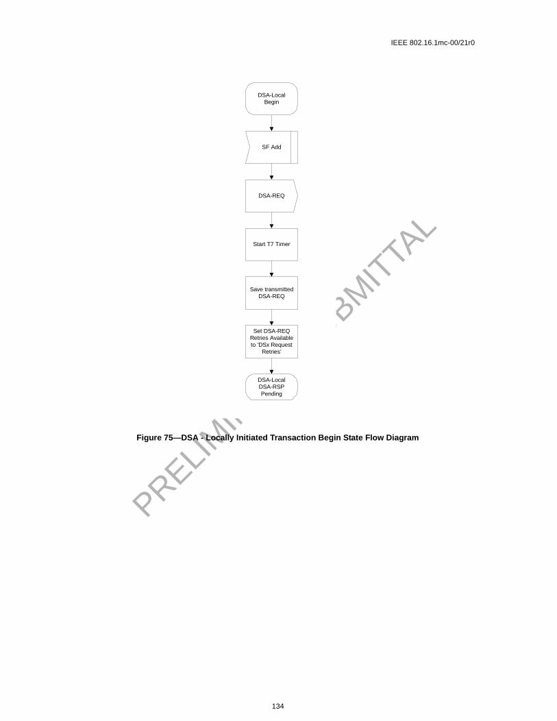
IEEE 802.16.1mc-00/21r0
PRELIM
INARY S
UBMIT
TAL
Figure 75—DSA - Locally Initiated Transaction Begin State Flow Diagram
SF Add
DSA-LocalBegin
Set DSA-REQRetries Availableto ’DSx Request
Retries’
DSA-REQ
Start T7 Timer
Save transmittedDSA-REQ
DSA-LocalDSA-RSPPending
134

IEEE 802.16.1mc-00/21r0
PRELIM
INARY S
UBMIT
TAL
Figure 76—DSA - Locally Initiated Transaction DSA-RSP Pending State Flow Diagram
DSA-LocalDSA-RSPPending
DSA-RSPSF Abort Add
Stop T7 TimerStop T7 Timer
DSA Failed
Save DSA-ACKwith Condition
Code ’reject-add-aborted’
Set ConditionCode to ’reject-xxx’
Okay ?
Yes
Enableservice flow
DSASucceeded
Set ConditionCode to ’okay’
DSA-ACK
Save transmittedDSA-ACK
DSA-LocalHolding Down
Start T10 Timer
Timeout T7 SF Delete-Remote
Stop T7 Timer
DSA Ended
DSA-LocalEnd
RetriesAvailable
?
Yes
Start T10 Timer
DSA-LocalDSA-RSPPending
DSA-LocalRetries Exhausted
DecrementDSA-REQ
Retries Available
SavedDSA-REQ
Start T7 Timer
No
No
135

IEEE 802.16.1mc-00/21r0
PRELIM
INARY S
UBMIT
TAL
Figure 77—DSA - Locally Initiated Transaction Holding State Flow Diagram
DSA-LocalHolding Down
Timeout T10 DSA-RSP
SavedDSA-ACK
DSA ACKLost
DSA-LocalHolding Down
SF Changed,SF Change-Remote,SF Delete-Remote
SF Delete-Local
DSA-LocalDeleting
Service FlowStop T10 Timer
DSA Ended
DSA-LocalEnd
136

IEEE 802.16.1mc-00/21r0
PRELIM
INARY S
UBMIT
TAL
Figure 78—DSA - Locally Initiated Transaction Retries Exhausted State Flow Diagram
DSA-LocalRetries Exhausted
Timeout T10 SF Delete-Remote DSA-RSPSF Abort Add
DSA Failed
Save DSA-ACKwith Condition
Code ’reject-add-aborted’
Stop T10 TimerDSA Erred
DSA Ended
DSA-LocalEnd
Okay ?
Yes
Set ConditionCode to ’reject-xxx’
Set ConditionCode to ’okay’
DSA-ACK
Save transmittedDSA-ACK
DSA-LocalHolding Down
Enableservice flow
DSASucceeded
No
137

IEEE 802.16.1mc-00/21r0
PRELIM
INARY S
UBMIT
TAL
Figure 79—DSA - Locally Initiated Transaction Deleting Service Flow State Flow Diagram
DSA-LocalDeleting
Service Flow
Timeout T10SF Deleted,
SF Delete-Remote
Stop T10 Timer
DSA Ended
DSA-LocalEnd
DSA-RSP
DSA ACKLost
DSA-LocalDeleting
Service Flow
138

IEEE 802.16.1mc-00/21r0
PRELIM
INARY S
UBMIT
TAL
DSA-RemoteBegin
DSA-REQ
Okay ?
Yes
[ CMTS Only ]Enable
upstreamservice flow
[ CM Only ]Enable
downstreamservice flow
DSA Failed
Set ConditionCode to ’okay’
Set ConditionCode to ’reject-xxx’
DSA-RemoteDSA-ACKPending
Set DSA-RSPRetries Availableto ’DSx Response
Retries’
DSA-RSP
Start T8 Timer
Save transmittedDSA-RSP
No
Figure 80—DSA - Remotely Initiated Transaction Begin State Flow Diagram
139

IEEE 802.16.1mc-00/21r0
PRELIM
INARY S
UBMIT
TAL
Figure 81—DSA - Remotely Initiated Transaction DSA-ACK Pending State Flow Diagram
DSA-RemoteDSA-ACKPending
DSA-ACK
Stop T8 Timer
Okay ?
DSA Failed
Yes
[ CMTS Only ]Enable
downstreamservice flow
[ CM Only ]Enable
upstreamservice flow
DSASucceeded
Start T8 Timer
DSA-RemoteHolding Down
Disableservice flow
SF Delete-Local
Stop T8 Timer
Start T10 Timer
DSA-RemoteDeleting
Service Flow
DSA-REQSF DSA-ACK
LostSF Delete-
Remote
Stop T8 Timer
Timeout T8
RetriesAvailable
?
Yes
DSA-RemoteDSA-ACKPending
DSA Erred
DSA-RemoteEnd
DSA Ended
DecrementDSA-RSP
Retries Available
SavedDSA-RSP
Start T8 Timer
RetriesAvailable
?
Yes
SavedDSA-RSP
No
No
No
140

IEEE 802.16.1mc-00/21r0
PRELIM
INARY S
UBMIT
TAL
Figure 82—DSA - Remotely Initiated Transaction Holding Down State Flow Diagram
SF Changed,SF Deleted,
SF Delete-Remote
DSA-RemoteHolding Down
Timeout T8 DSA-ACK
DSA-RemoteHolding Down
SF Delete-Local,SF Change-Remote
Stop T8 Timer
DSA Ended
DSA-RemoteEnd
141

IEEE 802.16.1mc-00/21r0
eduling
avior is simul-
a func-se” in
PRELIM
INARY S
UBMIT
TAL
6.10.10 Dynamic Service Change
The Dynamic Service Change (DSC) set of Messages is used to modify the flow parameters associated witha Service Flow. Specifically, DSC can:
a) Modify the Service Flow Specificationb) Add, Delete or Replace a Flow Classifierc) Add, Delete or Set PHS elements
A single DSC Message exchange can modify the parameters of one downstream service flow and/or oneupstream service flow.
To prevent packet loss, any required bandwidth change is sequenced between the CPE and BS.
The BS controls both upstream and downstream scheduling. The timing of scheduling changes is indepen-dent of direction AND whether it’s an increase or decrease in bandwidth. The BS always changes schon receipt of a DSC-REQ (CPE initiated transaction) or DSC-RSP (BS initiated transaction).
The BS also controls the downstream transmit behavior. The change in downstream transmit behalways coincident with the change in downstream scheduling (i.e. BS controls both and changes bothtaneously).
The CPE controls the upstream transmit behavior. The timing of CPE transmit behavior changes is tion of which device initiated the transaction AND whether the change is an “increase” or “decreabandwidth.
Figure 83—DSA - Remotely Initiated Transaction Deleting Service State Flow Diagram
DSA-RemoteDeleting
Service Flow
Timeout T10SF Deleted,
SF Delete-Remote
Stop T10 Timer
DSA Ended
DSA-RemoteEnd
DSA-REQ,DSA-ACK
DSA-RemoteDeleting
Service Flow
142

IEEE 802.16.1mc-00/21r0
irst andndwidthhe CPE
dwidthC sig-sifiersC-Ack
C-REQever, iferefore, duringtil the
ransac-nsac-
saction trans-
MUSTnamic
PRELIM
INARY S
UBMIT
TAL
If an upstream Service Flow’s bandwidth is being reduced, the CPE reduces its payload bandwidth fthen the BS reduces the bandwidth scheduled for the Service Flow. If an upstream Service Flow’s bais being increased, the BS increases the bandwidth scheduled for the Service Flow first and then tincreases its payload bandwidth.
If the bandwidth changes are complex, it may not be obvious to the CPE when to effect the banchanges. This information may be signalled to the CPE from a higher layer entity. Similarly, if the DSnaling is initiated by the BS, the BS MAY indicate to the CPE whether it should install or remove Clasupon receiving the DSC-Request or whether it should postpone this installation until receiving the DS(refer to C.2.1.9)
Any service flow can be deactivated with a Dynamic Service Change command by sending a DSMessage, referencing the Service Flow Identifier, and including a null ActiveQoSParameterSet. Howa Primary Service Flow of a CPE is deactivated that CPE is de-registered and MUST re-register. Thcare should be taken before deactivating such Service Flows. If a Service Flow that was provisionedregistration is deactivated, the provisioning information for that Service Flow MUST be maintained unService Flow is reactivated.
A CPE MUST have only one DSC transaction outstanding per Service Flow. If it detects a second ttion initiated by the BS, the CPE MUST abort the transaction it initiated and allow the BS initiated tration to complete.
A BS MUST have only one DSC transaction outstanding per Service Flow. If it detects a second traninitiated by the CPE, the BS MUST abort the transaction the CPE initiated and allow the BS initiatedaction to complete.
Note: Currently anticipated applications would probably control a Service Flow through either the CPE or BS,and not both. Therefore the case of a DSC being initiated simultaneously by the CPE and BS is considered as anexception condition and treated as one.
6.10.10.1 CPE-Initiated Dynamic Service Change
A CPE that needs to change a Service Flow definition performs the following operations.
The CPE informs the BS using a Dynamic Service Change Request Message (DSC-REQ). The BSdecide if the referenced Service Flow can support this modification. The BS MUST respond with a Dy
143

IEEE 802.16.1mc-00/21r0
PRELIM
INARY S
UBMIT
TAL
Service Change Response (DSC-RSP) indicating acceptance or rejection. The CPE reconfigures the ServiceFlow if appropriate, and then MUST respond with a Dynamic Service Change Acknowledge (DSC-ACK).
6.10.10.2 BS-Initiated Dynamic Service Change
A BS that needs to change a Service Flow definition performs the following operations.
The BS MUST decide if the referenced Service Flow can support this modification. If so, the BS informs theCPE using a Dynamic Service Change Request Message (DSC-REQ). The CPE checks that it can supportthe service change, and MUST respond using a Dynamic Service Change Response (DSC-RSP) indicatingacceptance or rejection. The BS reconfigures the Service Flow if appropriate, and then MUST respond witha Dynamic Service Change Acknowledgment (DSC-ACK)
BS CPE
Service Flow Requires Modifying
Receive DSC-REQ <--------- DSC-REQ ---------- Send DSC-REQ
Validate Request
Modify Service Flow
Increase Channel Bandwidth if Required
Send DSC-RSP ---------- DSC-RSP ---------> Receive DSC-RSP
Modify Service Flow
Adjust Payload Bandwidth
Receive DSC-ACK <--------- DSC-ACK ---------- Send DSC-ACK
Decrease Channel Bandwidth if Required
Table 20—CPE-Initiated DSC
BS CPE
Service Flow Requires Modifying
Send DSC-REQ ---------- DSC-REQ ---------> Receive DSC-REQ
Modify Service Flow
Decrease Payload Bandwidth if Required
Receive DSC-RSP <--------- DSC-RSP ---------- Send DSC-RSP
Modify Service Flow
Adjust Channel Bandwidth
Send DSC-ACK ---------- DSC-ACK ---------> Receive DSC-ACK
Increase Payload Bandwidth if Required
Table 21—BS-Initiated DSC
144

IEEE 802.16.1mc-00/21r0
PRELIM
INARY S
UBMIT
TAL
6.10.10.3 Dynamic Service Change State Transition Diagrams
Figure 84—DSC - Locally Initiated Transaction Begin State Flow Diagram
Save service flowQoS state
DSC-LocalDSC-RSPPending
Set DSC-REQRetries Availableto ’DSx Request
Retries’
DSC-REQ
Start T7 Timer
Save transmittedDSC-REQ
[ CM Only ]If decrease upstream
bandwidth, modifytransmission
SF Change
DSC-LocalBegin
145

IEEE 802.16.1mc-00/21r0
PRELIM
INARY S
UBMIT
TAL
Figure 85—DSC - Locally Initiated Transaction DSC-RSP Pending State Flow Diagram
SF Delete-Local
DSC-RSP
Stop T7 Timer
Start T10 Timer
DSC-LocalDeleting
Service Flow
Stop T7 Timer
Restoreservice flowQoS state
DSC-LocalDSC-RSPPending
Okay ?
Yes
[ CMTS Only ]Modify schedule and,
if downstream,transmission
[ CM Only ]If increase upstreambandwidth, modify
transmission
SF DSC-REQLost
SF Change-Remote
[ CM Only ]
SF Delete-Remote
DSC-LocalEnd
Stop T7 Timer
DSC Ended
146

IEEE 802.16.1mc-00/21r0
PRELIM
INARY S
UBMIT
TAL
Figure 86—DSC - Locally Initiated Transaction Holding Down State Flow Diagram
DSC-LocalHolding Down
Timeout T10 DSC-RSP
SavedDSC-ACK
DSC ACKLost
DSC-LocalHolding Down
SF Changed,SF Change-Remote,SF Delete-Remote
SF Delete-Local
DSC-LocalDeleting
Service FlowStop T10 Timer
DSC Ended
DSC-LocalEnd
147
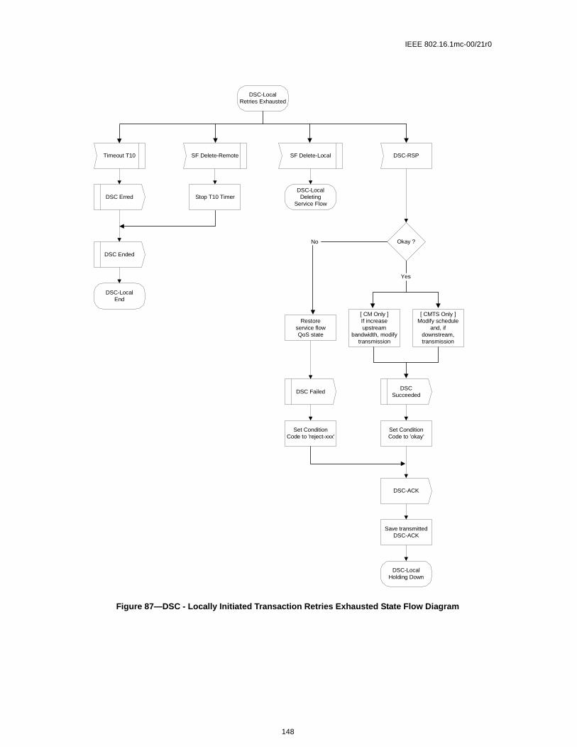
IEEE 802.16.1mc-00/21r0
PRELIM
INARY S
UBMIT
TAL
Figure 87—DSC - Locally Initiated Transaction Retries Exhausted State Flow Diagram
DSC-LocalRetries Exhausted
DSC-RSPSF Delete-LocalSF Delete-RemoteTimeout T10
Stop T10 TimerDSC Erred
DSC Ended
DSC-LocalEnd
DSC-LocalDeleting
Service Flow
Okay ?
[ CMTS Only ]Modify schedule
and, ifdownstream,transmission
[ CM Only ]If increaseupstream
bandwidth, modifytransmission
Set ConditionCode to ’okay’
DSC-ACK
Save transmittedDSC-ACK
DSC-LocalHolding Down
DSCSucceeded
Restoreservice flowQoS state
DSC Failed
Set ConditionCode to ’reject-xxx’
No
Yes
148

IEEE 802.16.1mc-00/21r0
PRELIM
INARY S
UBMIT
TAL
Figure 88—DSC - Locally Initiated Transaction Deleting Service Flow State Flow Diagram
DSC-LocalDeleting
Service Flow
Timeout T10SF Deleted,
SF Delete-Remote
Stop T10 Timer
DSC Ended
DSC-LocalEnd
DSC-RSP
DSC ACKLost
DSC-LocalDeleting
Service Flow
149

IEEE 802.16.1mc-00/21r0
PRELIM
INARY S
UBMIT
TAL
Figure 89—DSC - Remotely Initiated Transaction Begin State Flow Diagram
Okay ?
Yes
[ CMTS Only ]Modify schedule and,
if downstream,transmission
[ CM Only ]If decrease upstream
bandwidth, modifytransmission
Set ConditionCode to ’okay’
Set ConditionCode to ’reject-xxx’
DSC-RemoteDSC-ACKPending
Set DSC-RSPRetries Availableto ’DSx Response
Retries’
DSC-RSP
Start T8 Timer
Save transmittedDSC-RSP
DSC-RemoteBegin
DSC-REQ
Save service flowQoS state
No
150

IEEE 802.16.1mc-00/21r0
PRELIM
INARY S
UBMIT
TAL
\
Figure 90—DSC - Remotely Initiated Transaction DSC-ACK Pending State Flow Diagram
DSC-RemoteDSC-ACKPending
SF Delete-Local
Stop T8 Timer
Start T10 Timer
DSC-RemoteDeleting
Service Flow
DSC-ACK
Stop T8 Timer
Okay ?
Yes
[ CM Only ]If increaseupstream
bandwidth, modifytransmission
Restoreservice flowQoS state
DSC FailedDSC
Succeeded
Start T8 Timer
DSC-RemoteHolding Down
DSC-REQSF DSC-ACK
LostSF Delete-
Remote
Stop T8 Timer
Timeout T8
RetriesAvailable
?
Yes
DSC-RemoteDSC-ACKPending
DSC Erred
DSC-RemoteEnd
DSC Ended
DecrementDSC-RSP
Retries Available
SavedDSC-RSP
Start T8 Timer
RetriesAvailable
?
Yes
SavedDSC-RSP
No
No
No
151

IEEE 802.16.1mc-00/21r0
PRELIM
INARY S
UBMIT
TAL
Figure 91—DSC - Remotely Initiated Transaction Holding Down State Flow Diagram
DSC-RemoteEnd
SF Changed,SF Deleted,
SF Delete-Remote
DSC-RemoteHolding Down
Timeout T8 DSC-ACK
DSC-RemoteHolding Down
SF Delete-Local,SF Change-Remote
Stop T8 Timer
DSC Ended
152

IEEE 802.16.1mc-00/21r0
PRELIM
INARY S
UBMIT
TAL
6.10.11 Connection Release
Any service flow can be deleted with the Dynamic Service Deletion (DSD) Messages. When a Service Flow
153
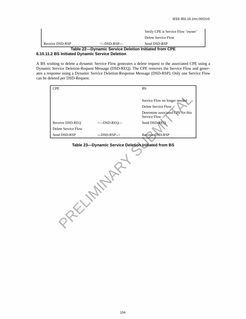
IEEE 802.16.1mc-00/21r0
PRELIM
INARY S
UBMIT
TAL
Table 22—Dynamic Service Deletion Initiated from CPE6.10.11.2 BS Initiated Dynamic Service Deletion
A BS wishing to delete a dynamic Service Flow generates a delete request to the associated CPE using aDynamic Service Deletion-Request Message (DSD-REQ). The CPE removes the Service Flow and gener-ates a response using a Dynamic Service Deletion-Response Message (DSD-RSP). Only one Service Flowcan be deleted per DSD-Request.
Table 23—Dynamic Service Deletion Initiated from BS
Verify CPE is Service Flow ‘owner’
Delete Service Flow
Receive DSD-RSP <--DSD-RSP--- Send DSD-RSP
CPE BS
Service Flow no longer needed
Delete Service Flow
Determine associated CPE for this Service Flow
Receive DSD-REQ <---DSD-REQ--- Send DSD-REQ
Delete Service Flow
Send DSD-RSP ---DSD-RSP--> Receive DSD-RSP
154

IEEE 802.16.1mc-00/21r0
PRELIM
INARY S
UBMIT
TAL
6.10.12 Dynamic Service Deletion State Transition Diagrams
Figure 93—DSD - Locally Initiated Transaction Begin State Flow Diagram
SF Delete
DSD-LocalBegin
DSD-LocalDSD-RSPPending
Set DSD-REQRetries Availableto ’DSx Request
Retries’
DSD-REQ
Start T7 Timer
Save transmittedDSD-REQ
Disableservice flow
155

IEEE 802.16.1mc-00/21r0
PRELIM
INARY S
UBMIT
TAL
Figure 94—DSD - Locally Initiated Transaction DSD-RSP Pending State Flow Diagram
DSD-LocalDSD-RSPPending
DSD-RSPSF Delete-Remote
DSD-LocalHolding Down
Start T7 Timer
Stop T7 Timer Stop T7 Timer
DSDSucceeded
SF DSD-REQLost
RetriesAvailable
?
Yes
SavedDSD-REQ
Timeout T7
RetriesAvailable
?
Yes
DSD Erred
DSD Ended
DSD-LocalEnd
DSD-LocalDSD-RSPPending
DecrementDSD-REQ
Retries Available
SavedDSD-REQ
Start T7 Timer
No
No
156

IEEE 802.16.1mc-00/21r0
PRELIM
INARY S
UBMIT
TAL
Figure 95—DSD - Locally Initiated Transaction Holding Down State Flow Diagram
DSD-LocalHolding Down
DSD-RSP
DSDSucceeded
DSD-LocalHolding Down
SF DeletedTimeout T7
DSD Ended
DSD-LocalEnd
157

IEEE 802.16.1mc-00/21r0
PRELIM
INARY S
UBMIT
TAL
Figure 96—DSD - Remotely Initiated Transaction Begin State Flow Diagram
DSD-RemoteBegin
Start T10 Timer
Save transmittedDSD-RSP
DSD-RemoteHolding Down
Disableservice flow
DSD-REQ
DSD-RSP
DSDSucceeded
158

IEEE 802.16.1mc-00/21r0
PRELIM
INARY S
UBMIT
TAL
159

IEEE 802.16.1mc-00/21r0
PRELIM
INARY S
UBMIT
TAL
160

IEEE 802.16.1mc-00/21r0
PRELIM
INARY S
UBMIT
TAL
161

IEEE 802.16.1mc-00/21r0
PRELIM
INARY S
UBMIT
TAL
162
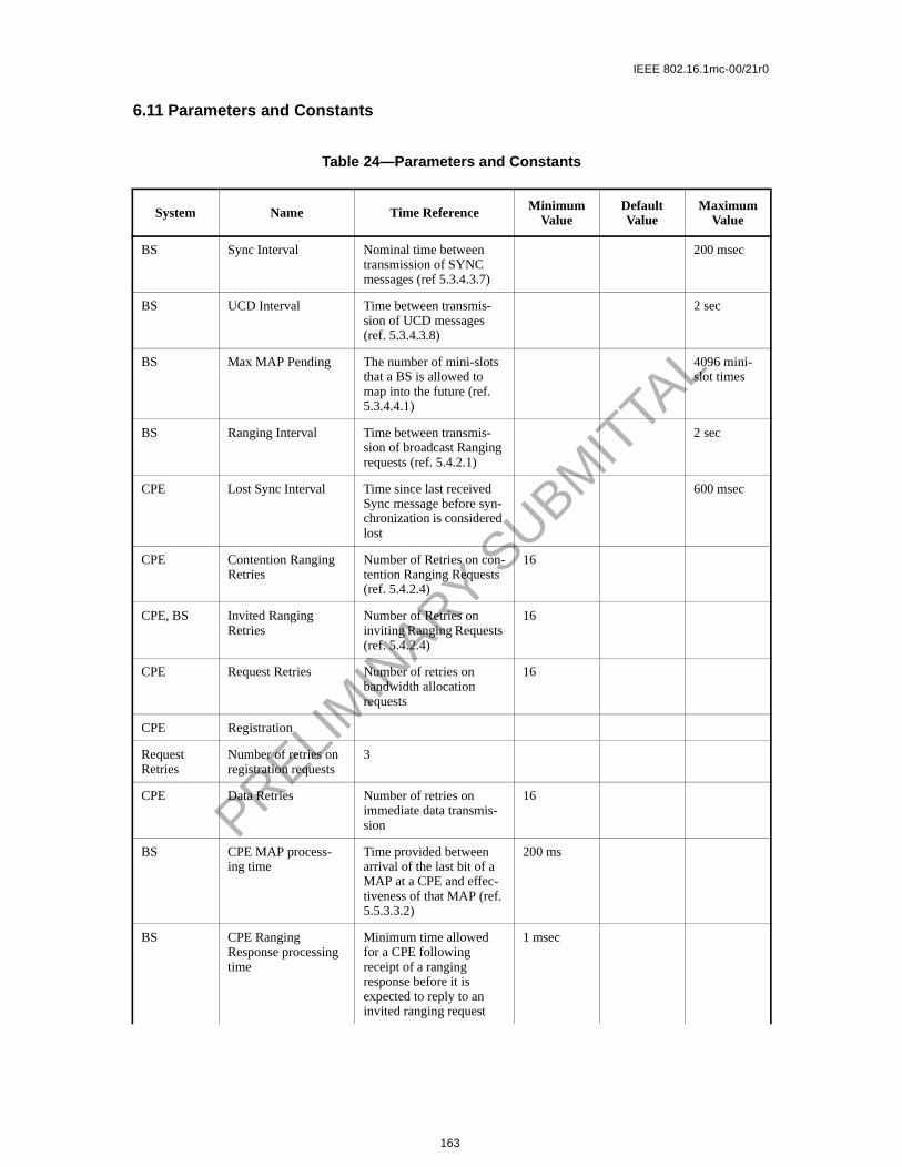
IEEE 802.16.1mc-00/21r0
PRELIM
INARY S
UBMIT
TAL
6.11 Parameters and Constants
Table 24—Parameters and Constants
System Name Time Reference Minimum Value
Default Value
Maximum Value
BS Sync Interval Nominal time between transmission of SYNC messages (ref 5.3.4.3.7)
200 msec
BS UCD Interval Time between transmis-sion of UCD messages (ref. 5.3.4.3.8)
2 sec
BS Max MAP Pending The number of mini-slots that a BS is allowed to map into the future (ref. 5.3.4.4.1)
4096 mini-slot times
BS Ranging Interval Time between transmis-sion of broadcast Ranging requests (ref. 5.4.2.1)
2 sec
CPE Lost Sync Interval Time since last received Sync message before syn-chronization is considered lost
600 msec
CPE Contention Ranging Retries
Number of Retries on con-tention Ranging Requests (ref. 5.4.2.4)
16
CPE, BS Invited Ranging Retries
Number of Retries on inviting Ranging Requests (ref. 5.4.2.4)
16
CPE Request Retries Number of retries on bandwidth allocation requests
16
CPE Registration
Request Retries
Number of retries on registration requests
3
CPE Data Retries Number of retries on immediate data transmis-sion
16
BS CPE MAP process-ing time
Time provided between arrival of the last bit of a MAP at a CPE and effec-tiveness of that MAP (ref. 5.5.3.3.2)
200 ms
BS CPE Ranging Response processing time
Minimum time allowed for a CPE following receipt of a ranging response before it is expected to reply to an invited ranging request
1 msec
163

IEEE 802.16.1mc-00/21r0
PRELIM
INARY S
UBMIT
TAL
BS CPE Configuration The maximum time allowed for a CPE, fol-lowing receipt of a config-uration file, to send a Registration Request to a BS.
30 sec
CPE T1 Wait for UCD timeout 5 * UCD interval maximum value
CPE T2 Wait for broadcast ranging timeout
5 * ranging interval
CPE T3 Wait for ranging response 50 msec 200 msec 200 msec
CPE T4 Wait for unicast ranging opportunity. If the pend-ing-till-complete field was used earlier by this modem, then the value of that field must be added to this interval.
30 sec 35 sec
BS T5 Wait for Upstream Chan-nel Change response
2 sec
CPE T6 Wait for registration response
3 sec
CPE
BS Mini-slot size Size of mini-slot for upstream transmission. Must be a power of 2 (in units of the Timebase Tick)
32 symbol times
CPE
BS Timebase Tick System timing unit 6.25 msec
CPE
BS DSx Request Retries Number of Timeout Retries on DSA/DSC/DSD Requests
3
CPE
BS DSx Response Retries Number of Timeout Retries on DSA/DSC/DSD Responses
3
CPE
BS T7 Wait for DSA/DSC/DSD Response timeout
1 sec
CPE
Table 24—Parameters and Constants
System Name Time Reference Minimum Value
Default Value
Maximum Value
164

IEEE 802.16.1mc-00/21r0
PRELIM
INARY S
UBMIT
TAL
6.12 Encodings for Configuration and MAC-Layer Messaging
The following type/length/value encodings MUST be used in both the configuration file (see <TBD>), in CPE registration requests and in Dynamic Service Messages. All multi-octet quantities are in network-byte order, i.e., the octet containing the most-significant bits is the first transmitted on the wire.
The following configuration settings MUST be supported by all CPEs which are compliant with this specification.
6.12.1 Configuration File and Registration Settings
These settings are found in the configuration file and, if present, MUST be forwarded by the CPE to the BS in its Registration Request.
BS T8 Wait for DSA/DSC Acknowledge timeout
300 msec
CPE TFTP Backoff Start Initial value for TFTP backoff
1sec
CPE TFTP Backoff End Last value for TFTP back-off
16 sec
CPE TFTP Request Retries Number of retries on TFTP request
16
CPE TFTP Download Retries
Number of retries on entire TFTP downloads
3
CPE TFTP Wait The wait between TFTP retry sequences
10 min
CPE ToD Retries Number of Retries per ToD Retry Period
3
CPE ToD Retry Period Time period for ToD retries
5 min
BS T9 Registration Timeout, the time allowed between the BS sending a RNG-RSP (success) to a CPE, and receiving a REG-REQ from that same CPE.
15 min 15 min
CPE
BS T10 Wait for Transaction End timeout
3 sec
Table 24—Parameters and Constants
System Name Time Reference Minimum Value
Default Value
Maximum Value
165
IEEE 802.16.1mc-00/21r0
the s lly, s (but
ioning
PRELIM
INARY S
UBMIT
TAL
6.12.1.1 Downstream Frequency Configuration Setting
The receive frequency to be used by the CPE. It is an override for the channel selected during scanning. This is the center frequency of the downstream channel in Hz stored as a 32-bit binary number.
Type Length Value1 4 Rx Frequency
Valid Range:The receive frequency MUST be a multiple of 1000 Hz.
6.12.1.2 Upstream Channel ID Configuration Setting
The upstream channel ID which the CPE MUST use. The CPE MUST listen on the defined downstream channel until an upstream channel description message with this ID is found. It is an override for the channel selected during initialization.
Type Length Value2 1 Channel ID
6.12.1.3 Network Access Control Object
If the value field is a 1, CPE attached to this CPE are allowed access to the network, based on CPE provisioning. If the value of this field is a 0, the CPE MUST NOT forward traffic from attached CPE to the RF MAC network, but MUST continue to accept and generate traffic from the CPE itself. The value of this field does not affect BS service flow operation and does not affect BS data forwarding operation.
Type Length On / Off3 1 1 or 0
Note: The intent of “NACO = 0” is that the CPE does not forward traffic from any attached CPE onto BWA network. (A CPE is any client device attached to that CPE, regardless of how that attachment iimplemented.) However, with “NACO = 0”, management traffic to the CPE is not restricted. Specificawith NACO off, the CPE remains manageable, including sending/receiving management traffic such anot limited to):
• ARP: allow the modem to resolve IP addresses, so it can respond to queries or send traps.
• DHCP: allow the modem to renew its IP address lease.
• ICMP: enable network troubleshooting for tools such as “ping” and “traceroute.”
• ToD: allow the modem to continue to synchronize its clock after boot.
• TFTP: allow the modem to download either a new configuration file or a new software image.
• SYSLOG: allow the modem to report network events.
• SNMP: allow management activity
With NACO off, the primary upstream and primary downstream service flows of the CPE remain operational only for management traffic to and from the CPE. With respect to BWA provisioning, a BSshould ignore the NACO value and allocate any service flows that have been authorized by the provisserver.
166

IEEE 802.16.1mc-00/21r0
cribers’s
fault
PRELIM
INARY S
UBMIT
TAL
6.12.1.4 Downstream Modulation Configuration Setting
The allowed downstream modulation types that can be used by the CPE.
Type Length Value4 1 bit #0: QPSK
bit #1: 16-QAMbit #2: 64-QAMbit #3-7: reserved must be set to zero
6.12.1.5 CPE Message Integrity Check (MIC) Configuration Setting
The value field contains the CPE message integrity check code. This is used to detect unauthorized modification or corruption of the configuration file.
Type Length Value6 16 d1 d2....... d16
6.12.1.6 BS Message Integrity Check (MIC) Configuration Setting
The value field contains the BS message integrity check code. This is used to detect unauthorized modification or corruption of the configuration file.
Type Length Value7 16 d1 d2....... d16
6.12.1.7 Maximum Number of Subscribers
The maximum number of Subcribers that can be granted access through a CPE during a CPE epoch. The CPE epoch is the time between startup and hard reset of the modem. The maximum number of SubsMUST be enforced by the CPE.
Type Length Value18 1
If present, the value MUST be positive and non-zero. The non-existence of this option means the devalue of 1.
Note: This is a limit on the maximum number of CPEs a CPE will grant access to. Hardware limitations of a given modem implementation may require the modem to use a lower value.
6.12.1.8 TFTP Server Timestamp
The sending time of the configuration file in seconds. The definition of time is as in [RFC-868]
Type Length Value19 4 Number of seconds since 00:00 1 Jan 1900
Note: The purpose of this parameter is to prevent replay attacks with old configuration files.
167

IEEE 802.16.1mc-00/21r0
y to
s. ice ne
PRELIM
INARY S
UBMIT
TAL
6.12.1.9 TFTP Server Provisioned Modem Address
The IP Address of the modem requesting the configuration file.
Type Length Value20 4 IP Address
Note: The purpose of this parameter is to prevent IP spoofing during registration.
6.12.1.10 Upstream Service Flow Encodings
This field defines the parameters associated with upstream scheduling for one Service Flow. Refer to Section 6.12.5.1.
Type Length Value24 n
6.12.1.11 Downstream Service Flow Encodings
This field defines the parameters associated with downstream scheduling for one Service Flow. Refer to Section 6.12.5.2.
Type Length Value
6.12.1.12 Privacy Enable
This configuration setting enables/disables Privacy on the Primary Service Flow and all other Service Flows for this CPE.
Type Length Value29 1 0 — Disable
1 — Enable
The default value of this parameter is 1 — privacy enabled.
6.12.1.13 Vendor-Specific Information
Vendor-specific information for CPE modems, if present, MUST be encoded in the vendor specific information field (VSIF) (code 43) using the Vendor ID field (6.12.3.2) to specify which TLV tuples applwhich vendors products. The Vendor ID MUST be the first TLV embedded inside VSIF. If the first TLVinside VSIF is not a Vendor ID, then the TLV must be discarded.
This configuration setting MAY appear multiple times. The same Vendor ID MAY appear multiple timeThis configuration setting MAY be nested inside a Packet Classification Configuration Setting, a ServFlow Configuration Setting, or a Service Flow Response. However, there MUST NOT be more than oVendor ID TLV inside a single VSIF.
Type Length Value43 n per vendor definition
Example:
Configuration with vendor A specific fields and vendor B specific fields:
168

IEEE 802.16.1mc-00/21r0
of this bject
e byte
PRELIM
INARY S
UBMIT
TAL
VSIF (43) + n (number of bytes inside this VSIF)8 (Vendor ID Type) + 3 (length field) + Vendor ID of Vendor AVendor A Specific Type #1 + length of the field + Value #1Vendor A Specific Type #2 + length of the field + Value #2
VSIF (43) + m (number of bytes inside this VSIF)8 (Vendor ID Type) + 3 (length field) + Vendor ID of Vendor BVendor B Specific Type + length of the field + Value
6.12.2 Configuration-File-Specific Settings
These settings are found in only the configuration file. They MUST NOT be forwarded to the BS in the Registration Request.
6.12.2.1 End-of-Data Marker
This is a special marker for end of data.
It has no length or value fields.
Type255
6.12.2.2 Pad Configuration Setting
This has no length or value fields and is only used following the end of data marker to pad the file to an integral number of 32-bit words.
Type0
6.12.2.3 Software Upgrade Filename
The filename of the software upgrade file for the CPE. The filename is a fully qualified directory-path name. The file is expected to reside on a TFTP server identified in a configuration setting option defined in Appendix D.2.2. See Section 5.3.1.3.1.1.
Type Length Value9 n filename
6.12.2.4 SNMP Write-Access Control
This object makes it possible to disable SNMP “Set” access to individual MIB objects. Each instance object controls access to all of the writeable MIB objects whose Object ID (OID) prefix matches. This omay be repeated to disable access to any number of MIB objects.
Type Length Value10 n OID prefix plus control flag
Where n is the size of the ASN.1 Basic Encoding Rules [ISO8025] encoding of the OID prefix plus onfor the control flag.
The control flag may take values:
169

IEEE 802.16.1mc-00/21r0
tion
PRELIM
INARY S
UBMIT
TAL
0 - allow write-access
1 - disallow write-access
Any OID prefix may be used. The Null OID 0.0 may be used to control access to all MIB objects. (The OID 1.3.6.1 will have the same effect.)
When multiple instances of this object are present and overlap, the longest (most specific) prefix has precedence. Thus, one example might be
someTabledisallow write-access
someTable.1.3allow write-access
This example disallows access to all objects in someTable except for someTable.1.3.
6.12.2.5 SNMP MIB Object
This object allows arbitrary SNMP MIB objects to be Set via the TFTP-Registration process.
Type Length Value11 n variable binding
where the value is an SNMP VarBind as defined in [RFC-1157]. The VarBind is encoded in ASN.1 Basic Encoding Rules, just as it would be if part of an SNMP Set request.
The CPE modem MUST treat this object as if it were part of an SNMP Set Request with the following caveats:
• It MUST treat the request as fully authorized (it cannot refuse the request for lack of privilege).
• SNMP Write-Control provisions (see previous section) do not apply.
• No SNMP response is generated by the CPE.
This object MAY be repeated with different VarBinds to “Set” a number of MIB objects. All such Sets MUST be treated as if simultaneous.
Each VarBind MUST be limited to 255 bytes.
6.12.2.6 CPE Ethernet MAC Address
This object configures the CPE with the Ethernet MAC address of a CPE device. This object may berepeated to configure any number of CPE device addresses.
Type Length Value14 6 Ethernet MAC Address of CPE
6.12.2.7 Software Upgrade TFTP Server
The IP address of the TFTP server, on which the software upgrade file for the CPE resides. See Sec5.3.1.3.1.1 and Appendix 6.12.2.3
Type Length Value21 4 ip1,ip2,ip3,ip4
170

IEEE 802.16.1mc-00/21r0
PRELIM
INARY S
UBMIT
TAL
6.12.3 Registration-Request/Response-Specific Encodings
These encodings are not found in the configuration file, but are included in the Registration Request. Some encodings are also used in the Registration Response.
The CPE MUST include Modem Capabilities Encodings in its Registration Request. If present in the corresponding Registration Request, the BS MUST include Modem Capabilities in the Registration Response.
6.12.3.1 Modem Capabilities Encoding
The value field describes the capabilities of a particular modem, i.e., implementation dependent limits on the particular features or number of features which the modem can support. It is composed from a number of encapsulated type/length/value fields. The encapsulated sub-types define the specific capabilities for the modem in question. Note that the sub-type fields defined are only valid within the encapsulated capabilities configuration setting string.
Type Length Value5 n
The set of possible encapsulated fields is described below.
6.12.3.1.1 Privacy Support
The value is the BPI support of the CPE.
Type Length Value5.6 1 0 Privacy Supported
1 - 255 Reserved
6.12.3.1.2 Upstream CID Support
The field shows the number of Upstream CIDs the modem can support.
Type Length Value5.8 1 Number of Upstream CIDs the CPE can support.
If the number of CIDs is 0 that means the Modem can support only 1 CID.
6.12.3.1.3 Transmit Equalizer Taps per Symbol
This field shows the maximal number of pre-equalizer taps per symbol supported by the CPE.
Note: All CPEs MUST support symbol-spaced equalizer coefficients. CPE support of 2 or 4 taps per symbol is optional. If this tuple is missing, it is implied that the CPE only supports symbol spaced equalizer coefficients.
Type Length Value5.10 1 1, 2 or 4
6.12.3.1.4 Number of Transmit Equalizer Taps
This field shows the number of equalizer taps that are supported by the CPE.
171

IEEE 802.16.1mc-00/21r0
PRELIM
INARY S
UBMIT
TAL
Note: All CPEs MUST support an equalizer length of at least 8 symbols. CPE support of up to 64 T-spaced, T/2-spaced or T/4-spaced taps is optional. If this tuple is missing, it is implied that the CPE only supports an equalizer length of 8 taps.
Type Length Value5.11 1 8 to 64
6.12.3.1.5 CPE Demodulator Types
This field indicates the different modulation types supported by the CPE for downstream reception.
Type Length Value5.12 1 bit #0: QPSK
bit #1: 16-QAMbit #2: 64-QAMbit #3: 8-PSKbit #4-7: reserved must be set to zero
6.12.3.1.6 CPE Modulator Types
This field indicates the different modulation types supported by the CPE for upstream transmission.
Type Length Value5.13 1 bit #0: QPSK
bit #1: 16-QAMbit #2: 64-QAMbit #3-7: reserved must be set to zero
6.12.3.1.7 Duplexing Support
This field indicates the different duplexing modes the CPE is able to support.
Type Length Value5.14 1 bit #0: FDD (continuous downstream)
bit #1: FDD (burst downstream)bit #2: Half-Duplex FDDbit #3: TDDbit #4-7: reserved must be set to zero
6.12.3.1.8 Bandwidth Allocation Support
This field indicates the different bandwidth allocation modes the CPE is able to support.
Type Length Value5.15 1 bit #0: Grant per Connection
bit #1: Grant per Terminal (CPE)bit #2-7: reserved must be set to zero
6.12.3.2 Vendor ID Encoding
The value field contains the vendor identification specified by the three-byte vendor-specific Organization Unique Identifier of the CPE MAC address.
172

IEEE 802.16.1mc-00/21r0
rithm,
ined in in
to
PRELIM
INARY S
UBMIT
TAL
The Vendor ID MUST be used in a Registration Request, but MUST NOT be used as a stand-alone configuration file element. It MAY be used as a sub-field of the Vendor Specific Information Field in a configuration file. When used as a sub-field of the Vendor Specific Information field, this identifies the Vendor ID of the CPEs which are intended to use this information. When the vendor ID is used in a Registration Request, then it is the Vendor ID of the CPE sending the request.
Type Length Value8 3 v1, v2, v3
6.12.3.3 Service(s) Not Available Response
This configuration setting MUST be included in the Registration Response message if the BS is unable or unwilling to grant any of the requested classes of service that appeared in the Registration Request. Although the value applies only to the failed service class, the entire Registration Request MUST be considered to have failed (none of the class-of-service configuration settings are granted).
Type Length Value13 3 Class ID, Type, Confirmation Code
Where
Class ID is the class-of-service class from the request which is not available
Type is the specific class-of-service object within the class which caused the request to be rejected
Confirmation Code Refer to 6.12.9.
6.12.4 Dynamic-Service-Message-Specific Encodings
These encodings are not found in the configuration file, nor in the Registration Request/Response signaling. They are only found in Dynamic Service Addition, Dynamic Service Change and Dynamic Service Deletion Request/Response messages:
6.12.4.1 HMAC-Digest
The HMAC-Digest setting is a keyed message digest. If privacy is enabled, the HMAC-Digest Attribute MUST be the final Attribute in the Dynamic Service message’s Attribute list. The message digest is performed over the all of the Dynamic Service parameters (starting immediately after the MAC Management Message Header and up to, but not including the HMAC Digest setting), other than theHMAC-Digest, in the order in which they appear within the packet.
Inclusion of the keyed digest allows the receiver to authenticate the message. The HMAC-Digest algoand the upstream and downstream key generation requirements are documented in [DOCSIS8].
This parameter contains a keyed hash used for message authentication. The HMAC algorithm is def[RFC2104]. The HMAC algorithm is specified using a generic cryptographic hash algorithm. BaselinePrivacy uses a particular version of HMAC that employs the Secure Hash Algorithm (SHA-1), defined[SHA].
A summary of the HMAC-Digest Attribute format is shown below. The fields are transmitted from left right.
Type Length Value27 20 A 160-bit (20 octet) keyed SHA hash
173

IEEE 802.16.1mc-00/21r0
Q nor
single if n is
ges, re in re.
re the es of
ewhat
share types
PRELIM
INARY S
UBMIT
TAL
6.12.4.2 Authorization Block
The Authorization Block contains an authorization “hint” from the CPE to the BS. The specifics of thecontents of this “hint” are beyond the scope of this specification, but include [PKT-DQOS].
The Authorization Block MAY be present in CPE-initiated DSA-REQ and DSC-REQ messages. This parameter MUST NOT be present in DSA-RSP and DSC-RSP message, nor in BS-initiated DSA-REDSC-REQ messages.
The Authorization Block information applies to the entire contents of the DSC message. Thus, only aAuthorization Block MAY be present per DSA-REQ or DSC-REQ message. The Authorization Block,present, MUST be passed to the Authorization Module in the BS. The Authorization Block informatioonly processed by the Authorization Module.
Type Length Value30 n Sequence of n octets
6.12.5 Quality-of-Service-Related Encodings
The following type/length/value encodings MUST be used in the configuration file, registration messaand Dynamic Service messages to encode parameters for Service Flows. All multi-octet quantities anetwork-byte order, i.e., the octet containing the most-significant bits is the first transmitted on the wi
The following configuration settings MUST be supported by all CPEs which are compliant with this specification.
6.12.5.1 Upstream Service Flow Encodings
This field defines the parameters associated with upstream scheduling for a Service Flow. It is somewhat complex in that is composed from a number of encapsulated type/length/value fields.
Note that the encapsulated upstream and downstream Service Flow configuration setting strings shasame subtype field numbering plan, because many of the subtype fields defined are valid for both typconfiguration settings. These type fields are not valid in other encoding contexts.
Type Length Value24 n
6.12.5.2 Downstream Service Flow Encodings
This field defines the parameters associated with downstream scheduling for a Service Flow. It is somcomplex in that is composed from a number of encapsulated type/length/value fields.
Note that the encapsulated upstream and downstream flow classification configuration setting stringsthe same subtype field numbering plan, because many of the subtype fields defined are valid for bothof configuration settings except Service Flow encodings.
Type Length Value25 n
174

IEEE 802.16.1mc-00/21r0
PRELIM
INARY S
UBMIT
TAL
6.12.5.3 General Service Flow Encodings
6.12.5.3.1 Service Flow Reference
The Service Flow Reference is used to associate a packet classifier encoding with a Service Flow encoding. A Service Flow Reference is only used to establish a Service Flow ID. Once the Service Flow exists and has an assigned Service Flow ID, the Service Flow Reference MUST no longer be used.
Type Length Value[24/25].1 2 1 - 65535
6.12.5.3.2 Service Flow Identifier
The Service Flow Identifier is used by the BS as the primary reference of a Service Flow. Only the BS can issue a Service Flow Identifier. It uses this parameterization to issue Service Flow Identifiers in BS-initiated DSA/DSC-Requests and in its REG/DSA/DSC-Response to CPE-initiated REG/DSA/DSC-Requests. The CPE specifies the SFID of a service flow using this parameter in a DSC-REQ message.
The configuration file MUST NOT contain this parameter.
Type Length Value[24/25].2 4 1 - 4,294,967,295
6.12.5.3.3 Service Identifier
The value of this field specifies the Service Identifier assigned by the BS to a Service Flow with a non-null AdmittedQosParameterSet or ActiveQosParameterSet. This is used in the bandwidth allocation MAP to assign upstream bandwidth. This field MUST be present in BS-initiated DSA-REQ or DSC-REQ message related to establishing an admitted or active upstream Service Flow. This field MUST also be present in REG-RSP, DSA-RSP and DSC-RSP messages related to the successful establishment of an admitted or active upstream Service Flow.
Even though a Service Flow has been successfully admitted or activated (i.e. has an assigned Service ID) the Service Flow ID MUST be used for subsequent DSx message signalling as it is the primary handle for a service flow. If a Service Flow is no longer admitted or active (via DSC-REQ) its Service ID MAY be reassigned by the BS.
SubType Length Value[24/25].3 2 SID (low-order 14 bits)
6.12.5.3.4 Service Class Name
The value of the field refers to a predefined BS service configuration to be used for this Service Flow.
Type Length Value[24/25].4 2 to 16 Zero-terminated string of ASCII characters.
Note: The length includes the terminating zero.
When the Service Class Name is used in a Service Flow encoding, it indicates that all the unspecified QoS Parameters of the Service Flow need to be provided by the BS. It is up to the operator to synchronize the definition of Service Class Names in the BS and in the configuration file.
175

IEEE 802.16.1mc-00/21r0
or DSC-
low one A-RSP
the Error
Error
ACK, e with
a rameter
Code in a
r
PRELIM
INARY S
UBMIT
TAL
6.12.5.4 Service Flow Error Encodings
This field defines the parameters associated with Service Flow Errors.
Type Length Value[24/25].5 n
A Service Flow Error Parameter Set is defined by the following individual parameters: Confirmation Code, Errored Parameter and Error Message.
The Service Flow Error Parameter Set is returned in REG-RSP, DSA-RSP and DSC-RSP messages to indicate the recipient’s response to a Service Flow establishment request in a REG-REQ, DSA-REQDSC-REQ message. The Service Flow Error Parameter Set is returned in REG-ACK, DSA-ACK andACK messages to indicate the recipient’s response to the expansion of a Service Class Name in a corresponding REG-RSP, DSA-RSP or DSC-RSP.
On failure, the sender MUST include one Service Flow Error Parameter Set for each failed Service Frequested in the REG-REQ, DSA-REQ or DSC-REQ message. On failure, the sender MUST includeService Flow Error Parameter Set for each failed Service Class Name expansion in the REG-RSP, DSor DSC-RSP message. Service Flow Error Parameter Set for the failed Service Flow MUST include Confirmation Code and Errored Parameter and MAY include an Error Message. If some Service FlowParameter Sets are rejected but other Service Flow Parameter Sets are accepted, then Service FlowParameters Sets MUST be included for only the rejected Service Flow.
On success of the entire transaction, the RSP or ACK message MUST NOT include a Service Flow Parameter Set.
Multiple Service Flow Error Parameter Sets MAY appear in a REG-RSP, DSA-RSP, DSC-RSP, REG-DSA-ACK or DSC-ACK message, since multiple Service Flow parameters may be in error. A messageven a single Service Flow Error Parameter Set MUST NOT contain any QoS Parameters.
A Service Flow Error Parameter Set MUST NOT appear in any REG-REQ, DSA-REQ or DSC-REQ messages.
6.12.5.4.1 Errored Parameter
The value of this parameter identifies the subtype of a requested Service Flow parameter in error in rejected Service Flow request or Service Class Name expansion response. A Service Flow Error PaSet MUST have exactly one Errored Parameter TLV within a given Service Flow Encoding.
Subtype Length Value[24/25].5.1 1 Service Flow Encoding Subtype in Error
6.12.5.4.2 Error Code
This parameter indicates the status of the request. A non-zero value corresponds to the Confirmationas described in 6.12.9. A Service Flow Error Parameter Set MUST have exactly one Error Code withgiven Service Flow Encoding.
Subtype Length Value[24/25].5.2 1 Confirmation code
A value of okay(0) indicates that the Service Flow request was successful. Since a Service Flow ErroParameter Set only applies to errored parameters, this value MUST NOT be used.
176

IEEE 802.16.1mc-00/21r0
PRELIM
INARY S
UBMIT
TAL
6.12.5.4.3 Error Message
This subtype is optional in a Service Flow Error Parameter Set. If present, it indicates a text string to be displayed on the CPE console and/or log that further describes a rejected Service Flow request. A Service Flow Error Parameter Set MAY have zero or one Error Message subtypes within a given Service Flow Encoding.
SubType Length Value[24/25].5.3 n Zero-terminated string of ASCII characters.
Note: The length N includes the terminating zero.
Note: The entire Service Flow Encoding message must have a total length of less than 256 characters.
6.12.5.5 Common Upstream and Downstream Quality-of-Service Parameter Encodings
The remaining Type 24 & 25 parameters are QoS Parameters. Any given QoS Parameter type MUST appear zero or one times per Service Flow Encoding.
6.12.5.5.1 Quality of Service Parameter Set Type
This parameter MUST appear within every Service flow Encoding. It specifies the proper application of the QoS Parameter Set: to the Provisioned set, the Admitted set, and/or the Active set. When two QoS Parameter Sets are the same, a multi-bit value of this parameter MAY be used to apply the QoS parameters to more than one set. A single message MAY contain multiple QoS parameter sets in separate type 24/25 Service Flow Encodings for the same Service Flow. This allows specification of the QoS Parameter Sets when their parameters are diferent. Bit 0 is the LSB of the Value field.
For every Service Flow that appears in a Registration-Request or Registration-Response message, there MUST be a Service Flow Encoding that specifies a ProvisionedQoSParameterSet. This Service Flow Encoding, or other Service Flow Encoding(s), MAY also specify an Admitted and/or Active set.
Type Length Value[24/25].6 1 Bit # 0 Provisioned Set
Bit # 1 Admitted SetBit # 2 Active Set
Table F-6. Values Used in REG-REQ and REG-RSP Messages
Value Messages
001 Apply to Provisioned set only
011 Apply to Provisioned and Admitted set, and perform admission control
101 Apply to Provisioned and Active sets, perform admission control, and activate this Service flow
111 Apply to Provisioned, Admitted, and Active sets; perform admission control and activate this Service Flow
177

IEEE 802.16.1mc-00/21r0
in bits
5.5).
PRELIM
INARY S
UBMIT
TAL
Table F-7. Values Used In Dynamic Service Messages.
A BS MUST handle a single update to each of the Active and Admitted QoS parameter sets. The ability to process multiple Service Flow Encodings that specify the same QoS parameter set is NOT required, and is left as a vendor-specific function. If a DSA/DSC contains multiple updates to a single QoS parameter set and the vendor does not support such updates, then the BS MUST reply with error code 2, reject-unrecognized-configuration-setting.
6.12.7.5.2 Traffic Priority
The value of this parameter specifies the priority assigned to a Service Flow. Given two Service Flows identical in all QoS parameters besides priority, the higher priority Service Flow SHOULD be given lower delay and higher buffering preference. For otherwise non-identical Service Flows, the priority parameter SHOULD NOT take precedence over any conflicting Service Flow QoS parameter. The specific algorithm for enforcing this parameter is not mandated here.
For upstream service flows, the BS SHOULD use this parameter when determining precedence in request service and grant generation, and the CPE MUST preferentially select contention Request opportunities for Priority Request Service IDs (refer to A.2.3) based on this priority and its Request/Transmission Policy (refer to 6.12.7.6.3).
Type Length Value[24/25].7 1 0 to 7 — Higher numbers indicate higher priority
Note: The default priority is 0.
6.12.7.5.3 Maximum Sustained Traffic Rate
This parameter is the rate parameter R of a token-bucket-based rate limit for packets. R is expressedper second, and must take into account all MAC frame data PDU of the Service Flow from the byte
following the MAC header HCS to the end of the CRC1. The number of bytes forwarded (in bytes) is limited during any time interval T by Max(T), as described in the expression
Max(T) = T * (R / 8) + B, (1)
where the parameter B (in bytes) is the Maximum Traffic Burst Configuration Setting (refer to 6.12.7.
Note: This parameter does not limit the instantaneous rate of the Service Flow.
Note: The specific algorithm for enforcing this parameter is not mandated here. Any implementation which satisfies the above equation is conformant.
Value Messages
000 Sect Active and Admitted sets to Null
010 Perform admission control and apply to Admitted set
100 Check against Admitted set in separate Service flow Encoding, perform admission control if needed, activate this Service Flow, and apply to Active set
110 Perform admission control and activate this Service Flow, apply parameters to both Admitted and Active sets
1The payload size includes every PDU in a Concatenated MAC Frame.
178

IEEE 802.16.1mc-00/21r0
n, up to
ention. is
ngth BS
ets that kets
ribed in e
1522
LD be
ocate
PRELIM
INARY S
UBMIT
TAL
Note: If this parameter is omitted or set to zero, then there is no explicitly-enforced traffic rate maximum. This field specifies only a bound, not a guarantee that this rate is available.
6.12.7.5.4 Upstream Maximum Sustained Traffic Rate
For an upstream Service Flow, the CPE MUST NOT request bandwidth exceeding the Max(T) requirement in (1) during any interval T because this could force the BS to fill MAPs with deferred grants.
The CPE MUST defer upstream packets that violate (1) and “rate shape” them to meet the expressioa limit as implemented by vendor buffering restrictions.
The BS MUST enforce expression (1) on all upstream data transmissions, including data sent in contThe BS MAY consider unused grants in calculations involving this parameter. The BS MAY enforce thlimit by any of the following methods: (a) discarding over-limit requests, (b) deferring (through zero-legrants) the grant until it is conforming to the allowed limit, or (c) discarding over-limit data packets. AMUST report this condition to a policy module. If the BS is policing by discarding either packets or requests, the BS MUST allow a margin of error between the CPE and BS algorithms.
Type Length Value24.8 4 R (in bits per second)
Downstream Maximum Sustained Traffic Rate
For a downstream Service Flow, this parameter is only applicable at the BS. The BS MUST enforce expression (1) on all downstream data transmissions. The BS MUST NOT forward downstream packviolates (1) in any interval T. The BS SHOULD “rate shape” the downstream traffic by enqueuing pacarriving in excess of (1), and delay them until the expression can be met.
This parameter is not intended for enforcement on the CPE.
Type Length Value25.8 4 R (in bits per second)
6.12.7.5.5 Maximum Traffic Burst
The value of this parameter specifies the token bucket size B (in bytes) for this Service Flow as descexpression (1). This value is calculated from the byte following the MAC header HCS to the end of th
CRC2.
If this parameter is omitted, then the default B is 1522 bytes. The minimum value of B is the larger ofbytes or the value of Maximum Concatenated Burst Size (refer to 6.12.7.6.1).
Type Length Value[24/25].9 4 B (bytes)
Note: The specific algorithm for enforcing this parameter is not mandated here. Any implementation which satisfies the above equation is conformant.
6.12.7.5.6 Minimum Reserved Traffic Rate
This parameter specifies the minimum rate, in bits/sec, reserved for this Service Flow. The BS SHOUable to satisfy bandwidth requests for a Service Flow up to its Minimum Reserved Traffic Rate. If lessbandwidth than its Minimum Reserved Traffic Rate is requested for a Service Flow, the BS MAY reall
2The payload size includes every PDU in a Concatenated MAC Frame.
179

IEEE 802.16.1mc-00/21r0
w’s DSC-itted
PRELIM
INARY S
UBMIT
TAL
the excess reserved bandwidth for other purposes. The aggregate Minimum Reserved Traffic Rate of all Service Flows MAY exceed the amount of available bandwidth. This value of this parameter is calculated
from the byte following the MAC header HCS to the end of the CRC3. If this parameter is omitted, then it defaults to a value of 0 bits/sec (i.e., no bandwidth is reserved for the flow by default).
This field is only applicable at the BS and MUST be enforced by the BS.
Type Length Value[24/25].10 4
Note: The specific algorithm for enforcing the value specified in this field is not mandated here.
6.12.7.5.7 Assumed Minimum Reserved Rate Packet Size
The value of this field specifies an assumed minimum packet size (in bytes) for which the Minimum Reserved Traffic Rate will be provided. This parameter is defined in bytes and is specified as the bytes
following the MAC header HCS to the end of the CRC4. If the Service Flow sends packets of a size smaller than this specified value, such packets will be treated as being of the size specified in this parameter for calculating the minimum Reserved Traffic Rate and for calculating bytes counts (e.g. bytes transmitted) which may ultimately be used for billing.
The BS MUST apply this parameter to its Minimum Reserved Traffic Rate algorithm. This parameter is used by the BS to estimate the per packet overhead of each packet in the service flow.
If this parameter is omitted, then the default value is BS implementation dependent.
Type Length Value[24/25].11 2
6.12.7.5.8 Timeout for Active QoS Parameters
The value of this parameter specifies the maximum duration resources remain unused on an active Service Flow. If there is no activity on the Service Flow within this time interval, the BS MUST change the active and admitted QoS Parameter Sets to null. The BS MUST signal this resource change with a DSC-REQ to the CPE.
If defined, this parameter MUST be enforced at the BS and SHOULD NOT be enforced at the CPE.
Type Length Value[24/25].12 2 seconds
The value of 0 means that the flow is of infinite duration and MUST NOT be timed out due to inactivity. The default value is 0.
6.12.7.5.9 Timeout for Admitted QoS Parameters
The value of this parameter specifies the duration that the BS MUST hold resources for a Service FloAdmitted QoS Parameter Set while they are in excess of its Active QoS Parameter Set. If there is noREQ to activate the Admitted QoS Parameter Set within this time interval, the resources that are adm
3The payload size includes every PDU in a Concatenated MAC Frame.4The payload size includes every PDU in a Concatenated MAC Frame.
180

IEEE 802.16.1mc-00/21r0
PRELIM
INARY S
UBMIT
TAL
but not activated MUST be released, and only the active resources retained. The BS MUST set the Admitted QoS Parameter Set equal to the Active QoS Parameter Set for the Service Flow and initiate a DSC-REQ exchange with the CPE to inform it of the change.
If this parameter is omitted, then the default value is 200 seconds. The value of 0 means that the Service Flow can remain in the admitted state for an infinite amount of time and MUST NOT be timed out due to inactivity. However, this is subject to policy control by the BS.
This parameter MUST be enforced by the BS. The BS MAY set the response value less than the requested value.
Type Length Value[24/25].13 2 seconds
6.12.7.5.10 Vendor Specific QoS Parameters
This allows vendors to encode vendor-specific QoS parameters. The Vendor ID MUST be the first TLV embedded inside Vendor Specific QoS Parameters. If the first TLV inside Vendor Specific QoS Parameters is not a Vendor ID, then the TLV must be discarded. (Refer to 6.12.1.13)
Type Length Value[24/25].43 n
6.12.7.6 Upstream-Specific QoS Parameter Encodings
6.12.7.6.1 Maximum Concatenated Burst
The value of this parameter specifies the maximum concatenated burst (in bytes) which a Service Flow is allowed. This parameter is calculated from the FC byte of the Concatenation MAC Header to the last CRC in the concatenated MAC frame.
A value of 0 means there is no limit. The default value is 0.
This field is only applicable at the CPE. If defined, this parameter MUST be enforced at the CPE.
Note: This value does not include any physical layer overhead.
Type Length Value24.14 2
Note: This applies only to concatenated bursts. It is legal and, in fact, it may be useful to set this smaller than the maximum Ethernet packet size. Of course, it is also legal to set this equal to or larger than the maximum Ethernet packet size.
6.12.7.6.2 Service Flow Scheduling Type
The value of this parameter specifies which upstream scheduling service is used for upstream transmission requests and packet transmissions. If this parameter is omitted, then the Best Effort service MUST be assumed.
181

IEEE 802.16.1mc-00/21r0
ta
d
r Spe-
is bit
iated rides
PRELIM
INARY S
UBMIT
TAL
This parameter is only applicable at the BS. If defined, this parameter MUST be enforced by the BS.
Type Length Value24.15 1 0 Reserved
1 for Undefined (BS implementation-dependent5)2 for Best Effort3 for Non-Real-Time Polling Service4 for Real-Time Polling Service5 for Unsolicited Grant Service with Activity Detection6 for Unsolicited Grant Service7 through 255 are reserved for future use
6.12.7.6.3 Request/Transmission Policy
The value of this parameter specifies which IUC opportunities the CPE uses for upstream transmission requests and packet transmissions for this Service Flow, whether requests for this Service Flow may be piggybacked with data and whether data packets transmitted on this Service Flow can be concatenated, fragmented, or have their payload headers suppressed. For UGS, it also specifies how to treat packets that do not fit into the UGS grant. See section 8.2 for requirements related to settings of the bits of this parameter for each Service Flow Scheduling Type.
This parameter is required for all Service Flow Scheduling Types except Best Effort. If omitted in a Best Effort Service Flow QoS parameter Set, the default value of zero MUST be used. Bit #0 is the LSB of the Value field. Bit 0 is the LSB of the Value field
Type Length Value24.16 4 Bit #0 The Service Flow MUST NOT use “all CPEs” broadcast request
opportunities.Bit #1 The Service Flow MUST NOT use Priority Request multicast request
opportunities. (Refer to A.2.3)Bit #2 The Service Flow MUST NOT use Request/Data opportunities for
RequestsBit #3 The Service Flow MUST NOT use Request/Data opportunities for DaBit #4 The Service Flow MUST NOT piggyback requests with data.Bit #5 The Service Flow MUST NOT concatenate data.Bit #6 The Service Flow MUST NOT fragment dataBit #7 The Service Flow MUST NOT suppress payload headers
Bit #86 The Service Flow MUST drop packets that do not fit in the Unsolicite
Grant Size7 All other bits are reserved.
Note: Data grants include both short and long data grants.
5The specific implementation dependent scheduling service type could be defined in the 24.43 Vendocific Information Field.
6This bit only applies to Service Flows with the Unsolicited Grant Service Flow Scheduling Type, if this set on any other Service Flow Scheduling type it MUST be ignored
7Packets that classify to an Unsolicited Grant Service Flow and are larger than the Grant Size assocwith that Service Flow are normally transmitted on the Primary Service Flow. This parameter overthat default behavior.
182

IEEE 802.16.1mc-00/21r0
PRELIM
INARY S
UBMIT
TAL
6.12.7.6.4 Nominal Polling Interval
The value of this parameter specifies the nominal interval (in units of microseconds) between successive unicast request opportunities for this Service Flow on the upstream channel. This parameter is typically suited for Real-Time and Non-Real-Time Polling Service.
The ideal schedule for enforcing this parameter is defined by a reference time t0, with the desired
transmission times ti = t0 + i*interval. The actual poll times, t’i MUST be in the range ti <= t’i <= ti + jitter, where interval is the value specified with this TLV, and jitter is Tolerated Poll Jitter. The accuracy of the ideal poll times, ti, are measured relative to the BS Master Clock used to generate timestamps (refer to Section 5.4.1.1).
This field is only applicable at the BS. If defined, this parameter MUST be enforced by the BS.
Type Length Value24.17 4 µsec
6.12.7.6.5 Tolerated Poll Jitter
The values in this parameter specifies the maximum amount of time that the unicast request interval MAY be delayed from the nominal periodic schedule (measured in microseconds) for this Service Flow.
The ideal schedule for enforcing this parameter is defined by a reference time t0, with the desired poll times
ti = t0 + i*interval. The actual poll, t’i MUST be in the range ti <= t’i <= ti + jitter, where jitter is the value specified with this TLV and interval is the Nominal Poll Interval. The accuracy of the ideal poll times, ti, are measured relative to the BS Master Clock used to generate timestamps (refer to Section 5.4.1.1).
This parameter is only applicable at the BS. If defined, this parameter represents a service commitment (or admission criteria) at the BS.
Type Length Value24.18 4 µsec
6.12.7.6.6 Unsolicited Grant Size
The value of this parameter specifies the unsolicited grant size in bytes. The grant size includes the entire MAC frame data PDU from the Frame Control byte to end of the MAC frame.
This parameter is applicable at the BS and MUST be enforced at the BS.
Type Length Value24.19 2
Note: For UGS, this parameter should be used by the BS to compute the size of the unsolicited grant in minislots.
6.12.7.6.7 Nominal Grant Interval
The value of this parameter specifies the nominal interval (in units of microseconds) between successive data grant opportunities for this Service Flow. This parameter is required for Unsolicited Grant and Unsolicited Grant with Activity Detection Service Flows.
183

IEEE 802.16.1mc-00/21r0
PRELIM
INARY S
UBMIT
TAL
The ideal schedule for enforcing this parameter is defined by a reference time t0, with the desired
transmission times ti = t0 + i*interval. The actual grant times, t’i MUST be in the range ti <= t’i <= ti + jitter, where interval is the value specified with this TLV, and jitter is the Tolerated Grant Jitter. When an upstream Service Flow with either Unsolicited Grant or Unsolicited Grant with Activity Detection scheduling becomes active, the first grant MUST define the start of this interval, i.e. the first grant MUST be for an ideal transmission time, ti. When multiple grants per interval are requested, all grants MUST be within this interval, thus the Nominal Grant Interval and Tolerated Grant Jitter MUST be maintained by the BS for all grants in this Service Flow. The accuracy of the ideal grant times, ti, are measured relative to the BS Master
Clock used to generate timestamps (refer to Section 5.4.1.1).
This field is mandatory for Unsolicited Grant and Unsolicited Grant with Activity Detection Scheduling Types. This field is only applicable at the BS, and MUST be enforced by the BS.
Type Length Value24.20 4 µsec
6.12.7.6.8 Tolerated Grant Jitter
The values in this parameter specifies the maximum amount of time that the transmission opportunities MAY be delayed from the nominal periodic schedule (measured in microseconds) for this Service Flow.
The ideal schedule for enforcing this parameter is defined by a reference time t0, with the desired transmission times ti = t0 + i*interval. The actual transmission opportunities, t’i MUST be in the range ti <= t’i <= ti + jitter, where jitter is the value specified with this TLV and interval is the Nominal Grant Interval. The accuracy of the ideal grant times, ti, are measured relative to the BS Master Clock used to generate
timestamps (refer to Section 5.4.1.1).
This field is mandatory for Unsolicited Grant and Unsolicited Grant with Activity Detection Scheduling Types. This field is only applicable at the BS, and MUST be enforced by the BS.
Type Length Value24.21 4 µsec
6.12.7.6.9 Grants per Interval
For Unsolicited Grant Service, the value of this parameter indicates the actual number of data grants per Nominal Grant Interval. For Unsolicited Grant Service with Activity Detection, the value of this parameter indicates the maximum number of Active Grants per Nominal Grant Interval. This is intended to enable the addition of sessions to an existing Unsolicited Grant Service Flow via the Dynamic Service Change mechanism, without negatively impacting existing sessions.
The ideal schedule for enforcing this parameter is defined by a reference time t0, with the desired transmission times ti = t0 + i*interval. The actual grant times, t’i MUST be in the range ti <= t’i <= ti + jitter, where interval is the Nominal Grant Interval, and jitter is the Tolerated Grant Jitter. When multiple grants per interval are requested, all grants MUST be within this interval, thus the Nominal Grant Interval and Tolerated Grant Jitter MUST be maintained by the BS for all grants in this Service Flow.
This field is mandatory for Unsolicited Grant and Unsolicited Grant with Activity Detection Scheduling Types. This field is only applicable at the BS, and MUST be enforced by the BS.
Type Length Value Valid Range24.22 1 # of grants 0-127
184

IEEE 802.16.1mc-00/21r0
PRELIM
INARY S
UBMIT
TAL
6.12.7.7 Downstream-Specific QoS Parameter Encodings
6.12.7.7.1 Maximum Downstream Latency
The value of this parameter specifies the maximum latency between the reception of a packet by the BS on its NSI and the forwarding of the packet to its RF Interface.
If defined, this parameter represents a service commitment (or admission criteria) at the BS and MUST be guaranteed by the BS. A BS does not have to meet this service commitment for Service Flows that exceed their minimum downstream reserved rate.
Type Length Value25.14 4 µsec
6.12.8 Privacy Configuration Settings Option
This configuration setting describes parameters which are specific to Privacy. It is composed from a number of encapsulated type/length/value fields.
Type Length Value17 (= P_CFG) n
6.12.9 Confirmation Code
The Confirmation Code (CC) provides a common way to indicate failures for Registration Response, Registration Ack, Dynamic Service Addition-Response, Dynamic Service Addition-Ack, Dynamic Service Delete-Response, Dynamic Service Change-Response and Dynamic Service Change-Ack MAC Management Messages.
Confirmation Codeis one of the following:
okay / success(0)
reject-other(1)
reject-unrecognized-configuration-setting(2)
reject-temporary / reject-resource(3)
reject-permanent / reject-admin(4)
reject-not-owner(5)
reject-service-flow-not-found(6)
reject-service-flow-exists(7)
reject-required-parameter-not-present(8)
reject-header-suppression(9)reject-unknown-transaction-id(10)reject-authentication-failure (11)
reject-add-aborted(12)
185

IEEE 802.16.1mc-00/21r0
PRELIM
INARY S
UBMIT
TAL
186

IEEE 802.16.1mc-00/21r0
PRELIM
INARY S
UBMIT
TAL
7. Authentication and Privacy
<TBD>
187

IEEE 802.16.1mc-00/21r0
PRELIM
INARY S
UBMIT
TAL
188

IEEE 802.16.1mc-00/21r0
189
PRELIM
INARY S
UBMIT
TAL
8. Transmission Convergence Sublayer
<TBD>


![Proposal to host IEEE 802.16 Interi m Session # 75 in ......[IEEE 802.16 Presentation Submission Template (Rev. 9.2)] Document Number: IEEE S802.16-11/0002 Date Submitted: 2011-03-14](https://img.pdfslide.us/doc/110x75/5f9a4e304a99154f0e363c65/proposal-to-host-ieee-80216-interi-m-session-75-in-ieee-80216-presentation.jpg)