Embed Size (px)
Citation preview
MECHATRONICS IN AUTOMOBILES
Daniel David George
PG 2 (Mechanical)
Roll no : 206
TKMCE
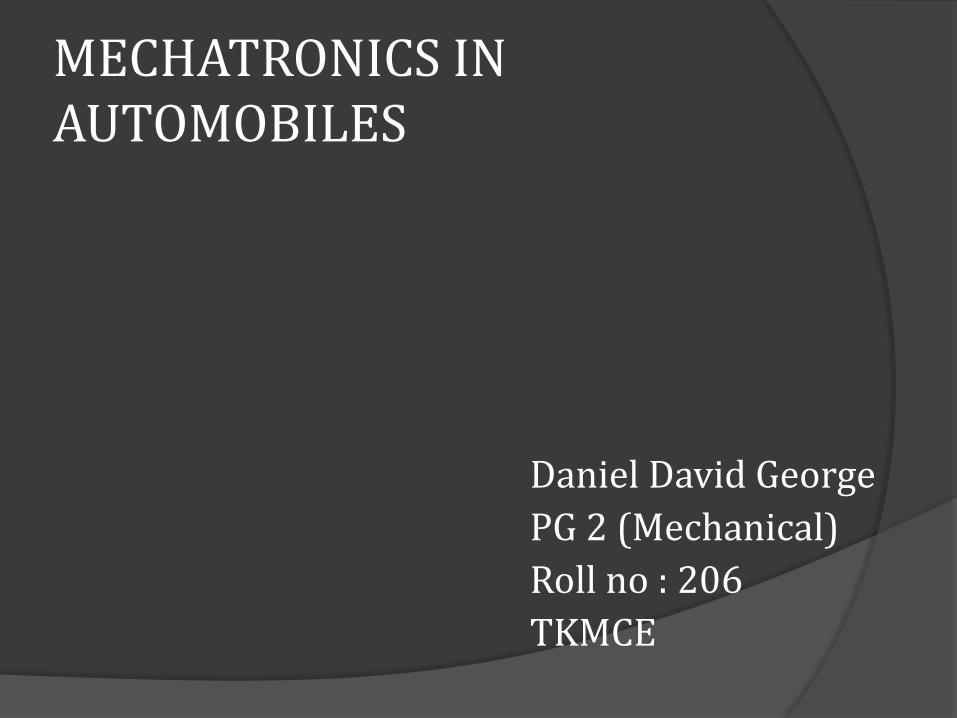
Anti Lock Braking System(ABS)
Locking is a situation in which, while hard braking one or many of the wheels seize to rotate forcing the vehicle to skid off the track.
ABS is a mechatronic system where mechanical, braking and hydraulic system and the electronic sensor system work in tandem to prevent wheel locking.
An ABS system consist of the following components:
1)Tandem Cylinder 2)Wheel sensor 3)ABS modulator 4)Hydraulic system(accumulators and pumps)
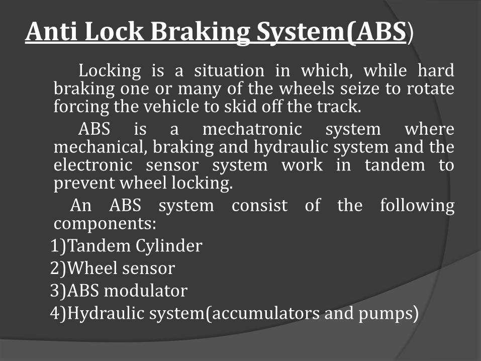
Main components of an ABS
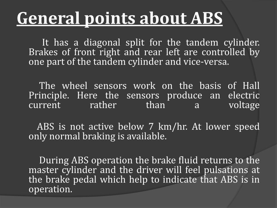
General points about ABS It has a diagonal split for the tandem cylinder.
Brakes of front right and rear left are controlled by one part of the tandem cylinder and vice-versa.
The wheel sensors work on the basis of Hall
Principle. Here the sensors produce an electric current rather than a voltage
ABS is not active below 7 km/hr. At lower speed only normal braking is available.
During ABS operation the brake fluid returns to the
master cylinder and the driver will feel pulsations at the brake pedal which help to indicate that ABS is in operation.
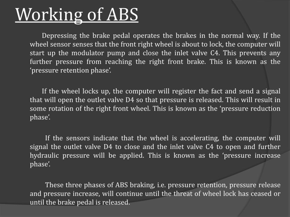
Working of ABS Depressing the brake pedal operates the brakes in the normal way. If the
wheel sensor senses that the front right wheel is about to lock, the computer will start up the modulator pump and close the inlet valve C4. This prevents any further pressure from reaching the right front brake. This is known as the ‘pressure retention phase’.
If the wheel locks up, the computer will register the fact and send a signal that will open the outlet valve D4 so that pressure is released. This will result in some rotation of the right front wheel. This is known as the ‘pressure reduction phase’.
If the sensors indicate that the wheel is accelerating, the computer will signal the outlet valve D4 to close and the inlet valve C4 to open and further hydraulic pressure will be applied. This is known as the ‘pressure increase phase’.
These three phases of ABS braking, i.e. pressure retention, pressure release and pressure increase, will continue until the threat of wheel lock has ceased or until the brake pedal is released.
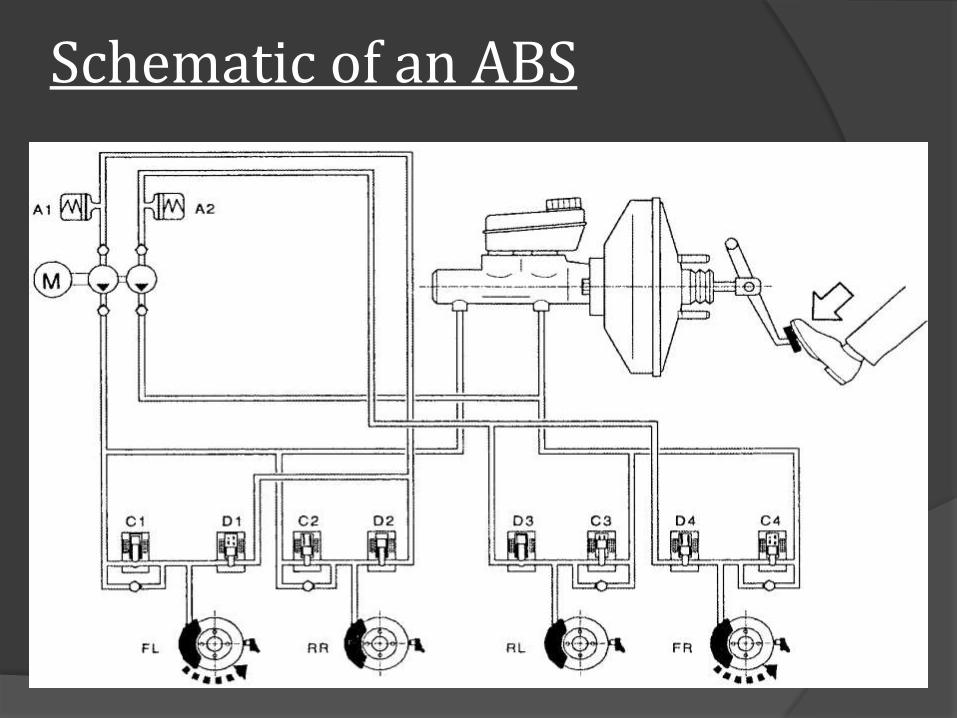
Schematic of an ABS
Vehicle behavior with ABS on and off
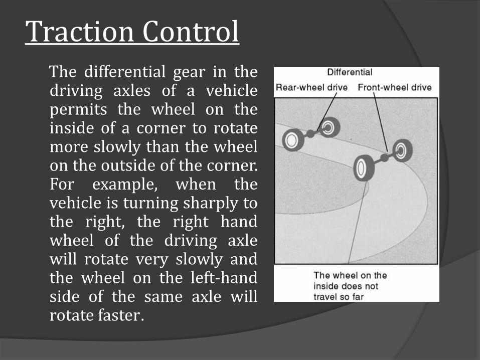
Traction Control The differential gear in the
driving axles of a vehicle permits the wheel on the inside of a corner to rotate more slowly than the wheel on the outside of the corner. For example, when the vehicle is turning sharply to the right, the right hand wheel of the driving axle will rotate very slowly and the wheel on the left-hand side of the same axle will rotate faster.
What is loss of traction? If for some reason one driving
wheel is on a slippery surface when an attempt is made to drive the vehicle away, this wheel will spin whilst the wheel on the other side of the axle will stand still. This will prevent the vehicle from moving. The loss of traction (propelling force) arises from the fact that the differential gear only permits transmission of torque equal to that on the weakest side of the axle. It takes very little torque to make a wheel spin on a slippery surface, so the small amount of torque that does reach the non-spinning wheel is not enough to cause the vehicle to move.
Working of traction control
Traction control enables the brake to be applied to the wheel on the slippery surface. This prevents the wheel from spinning and allows the drive to be transmitted to the other wheel. As soon as motion is achieved, the brake can be released and normal driving can be continued.
The ABS system contains most of the elements necessary for automatic application of the brakes, but it is necessary to provide additional valves and other components to permit individual wheel brakes to be applied.
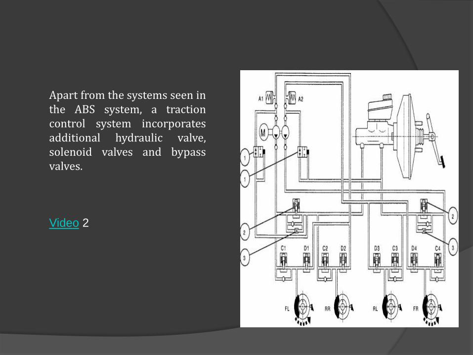
Apart from the systems seen in the ABS system, a traction control system incorporates additional hydraulic valve, solenoid valves and bypass valves.
Video 2
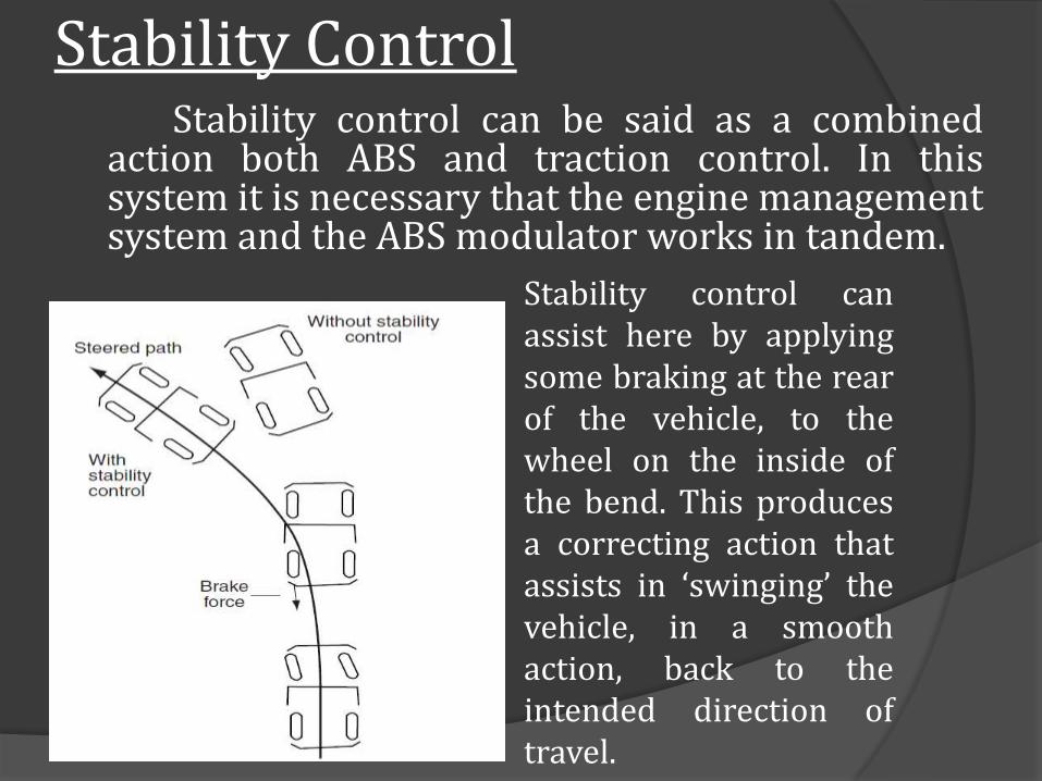
Stability Control Stability control can be said as a combined
action both ABS and traction control. In this system it is necessary that the engine management system and the ABS modulator works in tandem.
Stability control can assist here by applying some braking at the rear of the vehicle, to the wheel on the inside of the bend. This produces a correcting action that assists in ‘swinging’ the vehicle, in a smooth action, back to the intended direction of travel.
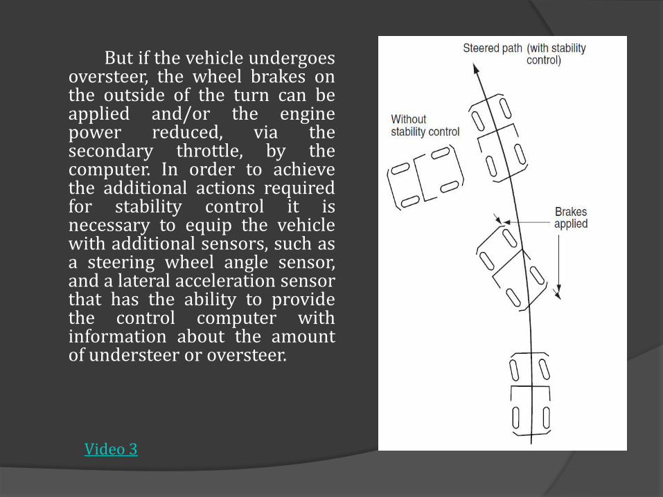
But if the vehicle undergoes oversteer, the wheel brakes on the outside of the turn can be applied and/or the engine power reduced, via the secondary throttle, by the computer. In order to achieve the additional actions required for stability control it is necessary to equip the vehicle with additional sensors, such as a steering wheel angle sensor, and a lateral acceleration sensor that has the ability to provide the control computer with information about the amount of understeer or oversteer.
Video 3
Terrain Response System
Normally, damping in a vehicle suspension system is achieved by forcing the suspension fluid through a small orifice. But in a terrain response system, the path through which the vehicle is travelling can be selected via an on board selector. By incorporating the signal from this system and the engine ECM the system calculate the terrain and adjust the suspension accordingly. The system can vary the size of the orifice so that the damping can be varied from stiff for asphalt surface for better handling and soft for off road conditions for extreme comfort
Future of Mechatronics
If the previous century belonged to IC engine vehicles for sustained mobility, the next century belongs to mechatronics for the development and fine tuning of newer technologies. Many unexplored regions are still to be developed so that the automobile experince can be enhanced.
Some of the new engines like Lotus Omnivore and Ricardo 2/4 sight are excellent examples to show the extend upto which mechatronics can travel in the future. It is indeed a promising field of mechanical engineering and we hope that can break new grounds with the onset of this new branch of engineering.
![HOME [hpigrp.com] · Clean your car—inside and out. Drive smoothly to avoid abrupt braking and hard accelerating. Avoid overloading. Check and rotate your tires. Choose quality](https://img.pdfslide.us/doc/110x75/5fa94e629f54162f362ea707/home-clean-your-carainside-and-out-drive-smoothly-to-avoid-abrupt-braking.jpg)

![REGENERATIVE BRAKING SYSTEM IN ELECTRIC VEHICLES · REGENERATIVE BRAKING SYSTEM IN ELECTRIC VEHICLES ... REGENERATIVE BRAKING SYSTEM ... Regenerative action during braking[9]](https://img.pdfslide.us/doc/110x75/5adccef67f8b9a1a088c7cf0/regenerative-braking-system-in-electric-vehicles-braking-system-in-electric-vehicles.jpg)