Embed Size (px)
Citation preview
PROCEEDINGS, 44th Workshop on Geothermal Reservoir Engineering
Stanford University, Stanford, California, February 11-13, 2019
SGP-TR-214
1
Mechanistically Modeling of Hydraulic Fracture Propagation and Interaction With
Natural Fractures at EGS-Collab Site
Hai Huang1, Ghanashyam H. Neupane1, Rob Podgorney1, Earl Mattson1 and EGS Collab Team2
1Energy and Environment Science and Technology Directorate, Idaho National Laboratory, Idaho Falls, ID83415, USA
Email: [email protected]
Keywords: EGS Collab, Hydraulic Fracturing, Natural Fracture, Modeling
ABSTRACT
In order to advance understandings of the relationships between stress, fracturing, induced seismicity and permeability enhancement, and
to provide rich data sets for model improvement and validation, the United States Department of Energy (DOE) Geothermal Technologies
Office (GTO) is funding a collaborative investigation of enhanced geothermal systems (EGS) processes at the intermediate-scale (~10-20
m), referred as the EGS Collab project. This project is envisioned to comprise field experiments and the site for the first experiment is on
the 4850ft Level below the ground in phyllite of the Precambrian Poorman formation within the Sanford Underground Research Facility
(SURF), located at the former Homestake Gold Mine in Lead, South Dakota. Natural fractures of various lengths, orientations,
permeability and mechanical cohesive strengths, are abundant within the EGS Collab site. In this study, aimed at interpreting stimulation
data and better understanding fracturing behaviors, a series of 2D and 3D simulations using coupled conjugate network flow and quasi-
static discrete element model (DEM) are performed. The fracturing behaviors of naturally fractured crystalline rocks under hydraulic
stimulations are investigated by systematically varying geometrical, hydraulic and mechanical attributes of natural fractures. Qualitative
comparisons with between the simulations and actual stimulation data is performed in this paper to indicate the significance of natural
heterogeneities on fracturing patterns and necessities of characterization of natural fractures and induced hydraulic fractures with
sufficiently high resolution.
1. INTRODUCTION
In October 2016, the United States Department of Energy (DOE), Geothermal Technologies Office (GTO) announced a funding
opportunity that was to be collaborative in nature and act as a research and development path between laboratory-scale stimulation and
rock mechanics studies and the large field scale of the future Frontier Observatory for Research in Geothermal Energy (FORGE)
investigations (U.S. Department of Energy, 2017). The recipient of the Collab award was announced in early 2017 to a project led by the
Lawrence Berkeley National Laboratory (LBNL), and initially termed the Stimulation Investigations for Geothermal Modeling Analysis
and Validation project, whose acronym referred to the symbol used for vertical stress (v). This collaborative project, now known as EGS
Collab, involves national laboratories, universities and private industry teaming to conduct stimulation and circulation experiments, and
verify computer codes, numerical algorithms and approaches, and process models against the generated data. This three-year project
(Kneafsey et al., 2018) has been tasked with providing new knowledge and modeling capabilities, forming a path from laboratory scale
to the field scale of FORGE. Each year during this project the Modeling and Simulation Working Group is responsible for reporting on
the state of numerical simulators and simulations associated with the project. During the first year of the project, numerical simulations
were generally directed at supporting the design of Experiment 1 (White et al., 2017; White et al., 2018). At that time, numerical
simulations were being conducted based on characterization data that were available from the kISMET project, which involved five
vertical or deviated vertical boreholes, also drilled from the 4850 drift (Oldenberg et al., 2016). Borehole logging at the kISMET site
revealed existing natural fracture and foliation features, but did not identify any open natural fractures, which supported the notion of the
host rock surrounding the kISMET boreholes as being of low permeability and clear of visible open fractures.
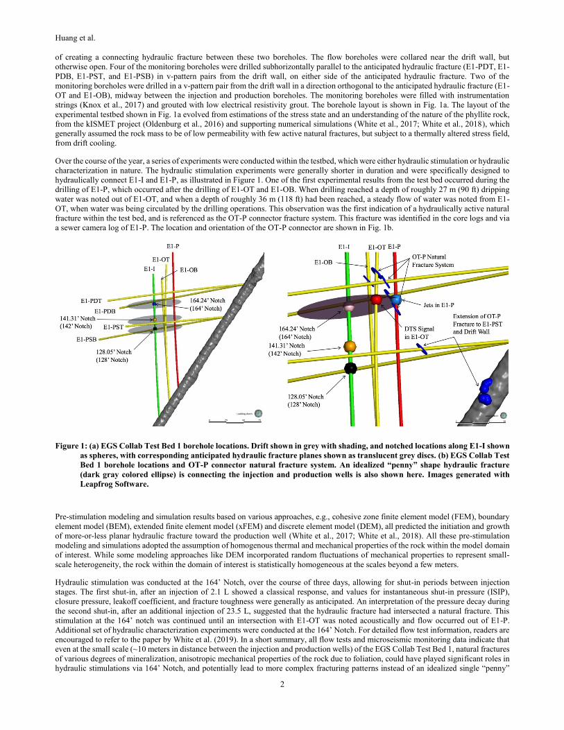
As illustrated in Figure 1, EGS Collab Experiment 1 has been conducted within a volume of predominately phyllite rock on the western
side of the 4850 Level (4,850 feet below ground surface) West Access Drift (drift) within Sanford Underground Research Facility (SURF)
near the kISMET site (Oldenburg et al., 2016). Eight boreholes were drilled into the experimental volume (Testbed 1); two boreholes
designed for flow and six boreholes designed for monitoring (Morris et al., 2018). The flow boreholes (E1-I injection, and E1-P
production) were drilled from the drift wall, nominally in the direction of the minimum principal horizontal stress (i.e., h), with the intent
2 J. Ajo-Franklin, S.J. Bauer, T. Baumgartner, K. Beckers, D. Blankenship, A. Bonneville, L. Boyd, S. Brown, S.T. Brown, J.A. Burghardt, T. Chen, Y. Chen, K.
Condon, P.J. Cook, D. Crandall, P.F. Dobson, T. Doe, C.A. Doughty, D. Elsworth, J. Feldman, A. Foris, L.P. Frash, Z. Frone, P. Fu, K. Gao, A. Ghassemi, H.
Gudmundsdottir, Y. Guglielmi, G. Guthrie, B. Haimson, A. Hawkins, J. Heise, M. Horn, R.N. Horne, J. Horner, M. Hu, H. Huang, L. Huang, K.J. Im, M. Ingraham,
R.S. Jayne, T.C. Johnson, B. Johnston, S. Karra, K. Kim, D.K. King, T. Kneafsey, H. Knox, J. Knox, D. Kumar, K. Kutun, M. Lee, K. Li, R. Lopez, M. Maceira, P. Mackey, N. Makedonska, C.J. Marone, E. Mattson, M.W. McClure, J. McLennan, T. McLing, C. Medler, R.J. Mellors, E. Metcalfe, J. Miskimins, J. Moore, J.P.
Morris, S. Nakagawa, G. Neupane, G. Newman, A. Nieto, C.M. Oldenburg, W. Pan, T. Paronish, R. Pawar, P. Petrov, B. Pietzyk, R. Podgorney, Y. Polsky, J. Popejoy
S. Porse, B.Q. Roberts, M. Robertson, W. Roggenthen, J. Rutqvist, D. Rynders, H. Santos-Villalobos, M. Schoenball, P. Schwering, V. Sesetty, C.S. Sherman, A.
Singh, M.M. Smith, H. Sone, F.A. Soom, C.E. Strickland, J. Su, D. Templeton, J.N. Thomle, C. Ulrich, N. Uzunlar, A. Vachaparampil, C.A. Valladao, W.
Vandermeer, G. Vandine, D. Vardiman, V.R. Vermeul, J.L. Wagoner, H.F. Wang, J. Weers, J. White, M.D. White, P. Winterfeld, T. Wood, S. Workman, H. Wu,
Y.S. Wu, Y. Wu, E.C. Yildirim, Y. Zhang, Y.Q. Zhang, J. Zhou, Q. Zhou, M.D. Zoback.
Huang et al.
2
of creating a connecting hydraulic fracture between these two boreholes. The flow boreholes were collared near the drift wall, but
otherwise open. Four of the monitoring boreholes were drilled subhorizontally parallel to the anticipated hydraulic fracture (E1-PDT, E1-
PDB, E1-PST, and E1-PSB) in v-pattern pairs from the drift wall, on either side of the anticipated hydraulic fracture. Two of the
monitoring boreholes were drilled in a v-pattern pair from the drift wall in a direction orthogonal to the anticipated hydraulic fracture (E1-
OT and E1-OB), midway between the injection and production boreholes. The monitoring boreholes were filled with instrumentation
strings (Knox et al., 2017) and grouted with low electrical resistivity grout. The borehole layout is shown in Fig. 1a. The layout of the
experimental testbed shown in Fig. 1a evolved from estimations of the stress state and an understanding of the nature of the phyllite rock,
from the kISMET project (Oldenburg et al., 2016) and supporting numerical simulations (White et al., 2017; White et al., 2018), which
generally assumed the rock mass to be of low permeability with few active natural fractures, but subject to a thermally altered stress field,
from drift cooling.
Over the course of the year, a series of experiments were conducted within the testbed, which were either hydraulic stimulation or hydraulic
characterization in nature. The hydraulic stimulation experiments were generally shorter in duration and were specifically designed to
hydraulically connect E1-I and E1-P, as illustrated in Figure 1. One of the first experimental results from the test bed occurred during the
drilling of E1-P, which occurred after the drilling of E1-OT and E1-OB. When drilling reached a depth of roughly 27 m (90 ft) dripping
water was noted out of E1-OT, and when a depth of roughly 36 m (118 ft) had been reached, a steady flow of water was noted from E1-
OT, when water was being circulated by the drilling operations. This observation was the first indication of a hydraulically active natural
fracture within the test bed, and is referenced as the OT-P connector fracture system. This fracture was identified in the core logs and via
a sewer camera log of E1-P. The location and orientation of the OT-P connector are shown in Fig. 1b.
Figure 1: (a) EGS Collab Test Bed 1 borehole locations. Drift shown in grey with shading, and notched locations along E1-I shown
as spheres, with corresponding anticipated hydraulic fracture planes shown as translucent grey discs. (b) EGS Collab Test
Bed 1 borehole locations and OT-P connector natural fracture system. An idealized “penny” shape hydraulic fracture
(dark gray colored ellipse) is connecting the injection and production wells is also shown here. Images generated with
Leapfrog Software.
Pre-stimulation modeling and simulation results based on various approaches, e.g., cohesive zone finite element model (FEM), boundary
element model (BEM), extended finite element model (xFEM) and discrete element model (DEM), all predicted the initiation and growth
of more-or-less planar hydraulic fracture toward the production well (White et al., 2017; White et al., 2018). All these pre-stimulation
modeling and simulations adopted the assumption of homogenous thermal and mechanical properties of the rock within the model domain
of interest. While some modeling approaches like DEM incorporated random fluctuations of mechanical properties to represent small-
scale heterogeneity, the rock within the domain of interest is statistically homogeneous at the scales beyond a few meters.
Hydraulic stimulation was conducted at the 164’ Notch, over the course of three days, allowing for shut-in periods between injection
stages. The first shut-in, after an injection of 2.1 L showed a classical response, and values for instantaneous shut-in pressure (ISIP),
closure pressure, leakoff coefficient, and fracture toughness were generally as anticipated. An interpretation of the pressure decay during
the second shut-in, after an additional injection of 23.5 L, suggested that the hydraulic fracture had intersected a natural fracture. This
stimulation at the 164’ notch was continued until an intersection with E1-OT was noted acoustically and flow occurred out of E1-P.
Additional set of hydraulic characterization experiments were conducted at the 164’ Notch. For detailed flow test information, readers are
encouraged to refer to the paper by White et al. (2019). In a short summary, all flow tests and microseismic monitoring data indicate that
even at the small scale (~10 meters in distance between the injection and production wells) of the EGS Collab Test Bed 1, natural fractures
of various degrees of mineralization, anisotropic mechanical properties of the rock due to foliation, could have played significant roles in
hydraulic stimulations via 164’ Notch, and potentially lead to more complex fracturing patterns instead of an idealized single “penny”
Huang et al.
3
shape hydraulic crack connecting the injection and production wells. The stimulation results indicate that the fracturing patterns at the test
bed could involve both tensile opening of new cracks and shear-openings of natural fractures, which leads to very complicated fracturing
patterns between the injection and production wells (~10 meters apart). One obvious challenge is to characterize the natural fractures
between the wells at sufficiently high resolution and certainty, and in addition, their hydraulic and mechanical properties, and spatial
connectivity. The hydraulic stimulation experiments also revealed an equally challenging difficulty of characterizing the size, shape and
growth pattern of the new opened hydraulic fracture itself.
This paper describes some post-stimulation two-dimensional (2D) and three-dimensional (3D) fracturing simulation results with the goal
of better understandings of the potential roles of natural factures on hydraulic fracture propagations during the 164’ Notch stimulation
experiment within the test bed. These post-stimulation fracturing simulations explicitly accounted for the presence of natural fractures
within the test bed. Sensitivity studies were carried out by systematically varying the mechanical and hydraulic properties of natural
fractures.
2. 2D SIMULATIONS OF HYDRAULIC FRACTURE INTERACTING WITH NATURAL FRACTURES
Propagation of hydraulic fracture and fracture aperture-permeability evolutions were simulated in 2D by a coupled network flow and
quasi-static discrete element model (DEM) (Zhou et al., 2017) developed at INL. The quasi-static DEM model, which is constructed by
Delaunay tessellation of the rock volume, considers small-scale rock-fabric heterogeneities by using the “disordered” DEM mesh and
adding random perturbations to the stiffness and tensile/shear strengths of individual DEM elements and the elastic beams between them.
A conjugate flow network based on the DEM lattice is then constructed to calculate the fluid flow in both the hydraulic fractures (including
natural fractures) and porous matrix. One distinctive advantage of the model is that fracturing is naturally described by the breakage of
elastic beams between DEM elements without complex and empirical ad hoc assumptions about fracture initiation and propagation
direction. It is also extremely convenient to introduce natural fractures into the model by simply “weakening” and/or removing DEM
bonds intersected by natural fractures.
A detailed description of this numerical simulator is provided in Zhou et al. (2017) and Huang et al. (2017), but a synopsis of the
computational approach will be described here. The simulation consists of interleaved fluid flow, mechanical relaxation of the DEM
network, recalculation of fracture permeability and beam breaking steps. The modeling of a hydraulic stimulation event starts with the
calculation of new fluid pressures at the new time (i.e., old time + time step). These single-phase flow calculations follow Darcy’s law,
using a finite-volume discretization with grid volumes centered on the conjugate flow node, and with the intrinsic permeability being
dependent on the spacing being DEM particles that have been cleaved (i.e., had a connecting elastic beam break). Updated fluid pressures
then act as forces on neighboring DEM particles, and the DEM network is relaxed to a new mechanical equilibrium by allowing the DEM
particles to be displaced and rotated. DEM particle displacements and rotations yield changes of stresses in the connecting beams. If a
beam connecting two DEM particles exceeds its failure criterion, then the beam is assumed to have broken, and is irreversibly removed
from the DEM network. As particle displacements/rotations and beam failures are sequential events, the mechanical equilibrium
computation is iterative, until no further beam breaking occurs, which concludes a time step.
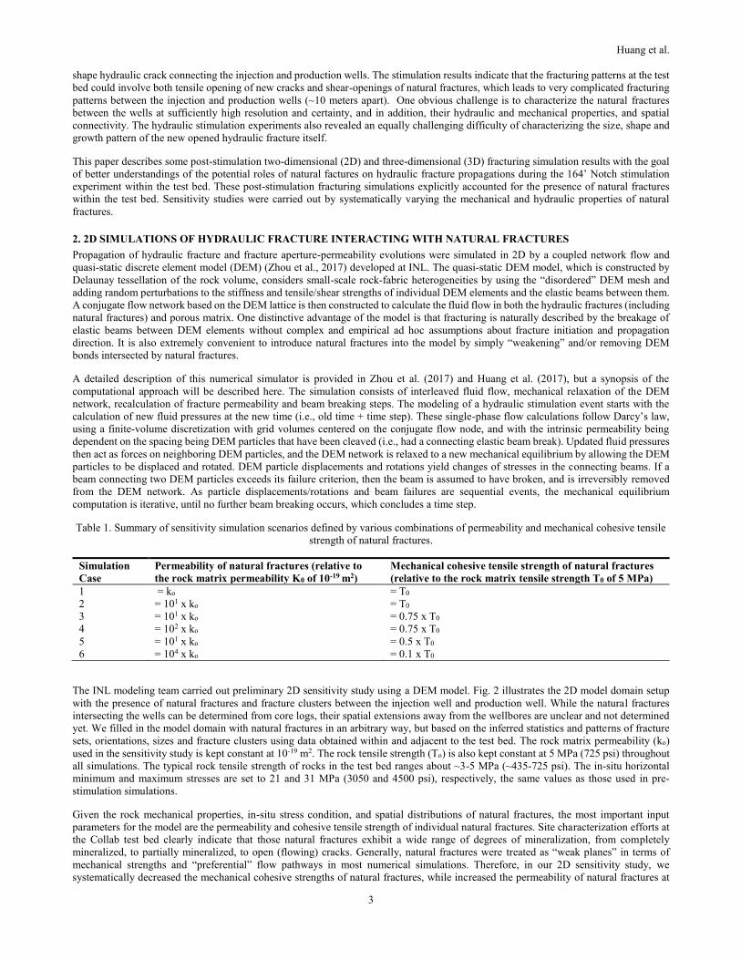
Table 1. Summary of sensitivity simulation scenarios defined by various combinations of permeability and mechanical cohesive tensile
strength of natural fractures.
Simulation
Case
Permeability of natural fractures (relative to
the rock matrix permeability K0 of 10-19 m2)
Mechanical cohesive tensile strength of natural fractures
(relative to the rock matrix tensile strength T0 of 5 MPa)
1 = ko = T0
2 = 101 x ko = T0
3 = 101 x ko = 0.75 x T0
4 = 102 x ko = 0.75 x T0
5 = 101 x ko = 0.5 x T0
6 = 104 x ko = 0.1 x T0
The INL modeling team carried out preliminary 2D sensitivity study using a DEM model. Fig. 2 illustrates the 2D model domain setup
with the presence of natural fractures and fracture clusters between the injection well and production well. While the natural fractures
intersecting the wells can be determined from core logs, their spatial extensions away from the wellbores are unclear and not determined
yet. We filled in the model domain with natural fractures in an arbitrary way, but based on the inferred statistics and patterns of fracture
sets, orientations, sizes and fracture clusters using data obtained within and adjacent to the test bed. The rock matrix permeability (ko)
used in the sensitivity study is kept constant at 10-19 m2. The rock tensile strength (To) is also kept constant at 5 MPa (725 psi) throughout
all simulations. The typical rock tensile strength of rocks in the test bed ranges about ~3-5 MPa (~435-725 psi). The in-situ horizontal
minimum and maximum stresses are set to 21 and 31 MPa (3050 and 4500 psi), respectively, the same values as those used in pre-
stimulation simulations.
Given the rock mechanical properties, in-situ stress condition, and spatial distributions of natural fractures, the most important input
parameters for the model are the permeability and cohesive tensile strength of individual natural fractures. Site characterization efforts at
the Collab test bed clearly indicate that those natural fractures exhibit a wide range of degrees of mineralization, from completely
mineralized, to partially mineralized, to open (flowing) cracks. Generally, natural fractures were treated as “weak planes” in terms of
mechanical strengths and “preferential” flow pathways in most numerical simulations. Therefore, in our 2D sensitivity study, we
systematically decreased the mechanical cohesive strengths of natural fractures, while increased the permeability of natural fractures at
Huang et al.
4
the same time. Table 1 summarizes all initial sensitivity simulation scenarios. We started first by assuming the natural fractures have
similar properties of the rock matrix, which essentially ignores the natural fractures (i.e., the pre-stimulation simulations). Then we
gradually increased the permeability of natural fractures with decreasing mechanical cohesive strength in the follow on simulation
scenarios.
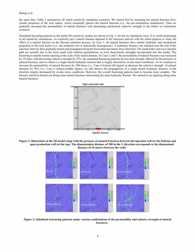
Simulated fracturing patterns in the initial 2D sensitivity studies are shown in Fig. 3, for the six simulation cases. It is worth mentioning
in all sensitivity simulations, we explicitly put a natural fracture adjacent to the injection interval with the initial purpose to study the
effect of a natural fracture on the fracture initiation process. In Case 1, all natural fractures have similar hydraulic and mechanical
properties to the rock matrix (i.e., the modeled rock is statistically homogenous). A hydraulic fracture was initiated near the end of the
injection interval, then gradually turned and propagated along the horizontal maximum stress direction. The small kinks and wavy fracture
path are actually due to the local small scale random perturbations on rock shear/tensile strengths incorporated into the model. The
fracturing is mainly tensile opening at the scale of the model domain. In Cases 2 and 3, the permeability of natural fractures was increased
by 10 times with decreasing cohesive strength by 25%, the simulated fracturing patterns do not seem strongly affected by the presence of
natural fractures, and we observe a single tensile hydraulic fracture that is largely directed by in-situ stress conditions. As we continue to
increase the permeability of natural fractures by 100 times (i.e., Case 4, bottom-left figure) or decrease the cohesive strength of natural
fractures by 50% (i.e., Case 5, bottom-middle figure), we still observe the propagations of a single tensile hydraulic fracture, in the
direction largely dominated by in-situ stress conditions. However, the overall fracturing patterns start to become more complex. The
fracture started to branch out along some natural fractures intersecting the main hydraulic fracture. We started to see opening along some
natural fractures.
Figure 2: Illustration of the 2D model setup with the presence of natural fractures between the injection well (at the bottom) and
open production well (at the top). The dimensionless distance of 200 in the Y direction corresponds to the dimensional
distance of 10 meters between the wells.
Figure 3: Simulated fracturing patterns under various combinations of the permeability and cohesive strength of natural
fractures.
Huang et al.
5
In the more extreme case (i.e., Case 6, bottom-right figure), the permeability of natural fractures was increased by 4 orders of magnitude,
and the cohesive strength was decreased by 90%, representing poorly mineralized, and permeable natural fractures with an equivalent
hydraulic aperture on the order of 0.1 micron. In this case, the fracturing is almost completely dominated by opening of natural fractures.
Once the natural fractures were pressured, we also observe multiple tensile openings from the tips of natural fracture, which was strongly
affected by the in-situ stress conditions. However, all these tensile-opened fractures would be arrested by natural fractures if they intersect
with natural fractures. The combined openings of natural fractures, multiple tensile opening fractures from the tips of pressurized natural
fractures, and propagation arresting together generated very complex fracturing pattern in the simulation, which poses significant
challenge to characterize them in the field with sufficient certainty and resolution.
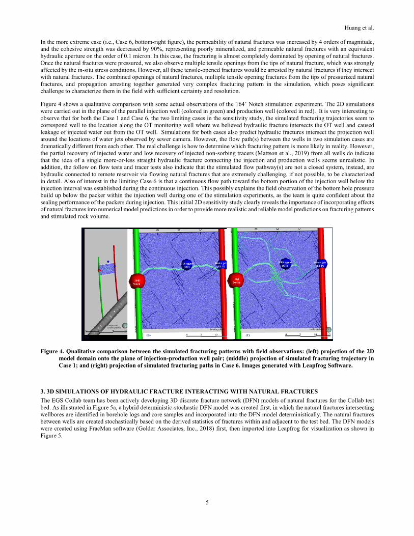
Figure 4 shows a qualitative comparison with some actual observations of the 164’ Notch stimulation experiment. The 2D simulations
were carried out in the plane of the parallel injection well (colored in green) and production well (colored in red). It is very interesting to
observe that for both the Case 1 and Case 6, the two limiting cases in the sensitivity study, the simulated fracturing trajectories seem to
correspond well to the location along the OT monitoring well where we believed hydraulic fracture intersects the OT well and caused
leakage of injected water out from the OT well. Simulations for both cases also predict hydraulic fractures intersect the projection well
around the locations of water jets observed by sewer camera. However, the flow path(s) between the wells in two simulation cases are
dramatically different from each other. The real challenge is how to determine which fracturing pattern is more likely in reality. However,
the partial recovery of injected water and low recovery of injected non-sorbing tracers (Mattson et al., 2019) from all wells do indicate
that the idea of a single more-or-less straight hydraulic fracture connecting the injection and production wells seems unrealistic. In
addition, the follow on flow tests and tracer tests also indicate that the stimulated flow pathway(s) are not a closed system, instead, are
hydraulic connected to remote reservoir via flowing natural fractures that are extremely challenging, if not possible, to be characterized
in detail. Also of interest in the limiting Case 6 is that a continuous flow path toward the bottom portion of the injection well below the
injection interval was established during the continuous injection. This possibly explains the field observation of the bottom hole pressure
build up below the packer within the injection well during one of the stimulation experiments, as the team is quite confident about the
sealing performance of the packers during injection. This initial 2D sensitivity study clearly reveals the importance of incorporating effects
of natural fractures into numerical model predictions in order to provide more realistic and reliable model predictions on fracturing patterns
and stimulated rock volume.
Figure 4. Qualitative comparison between the simulated fracturing patterns with field observations: (left) projection of the 2D
model domain onto the plane of injection-production well pair; (middle) projection of simulated fracturing trajectory in
Case 1; and (right) projection of simulated fracturing paths in Case 6. Images generated with Leapfrog Software.
3. 3D SIMULATIONS OF HYDRAULIC FRACTURE INTERACTING WITH NATURAL FRACTURES
The EGS Collab team has been actively developing 3D discrete fracture network (DFN) models of natural fractures for the Collab test
bed. As illustrated in Figure 5a, a hybrid deterministic-stochastic DFN model was created first, in which the natural fractures intersecting
wellbores are identified in borehole logs and core samples and incorporated into the DFN model deterministically. The natural fractures
between wells are created stochastically based on the derived statistics of fractures within and adjacent to the test bed. The DFN models
were created using FracMan software (Golder Associates, Inc., 2018) first, then imported into Leapfrog for visualization as shown in
Figure 5.
Huang et al.
6
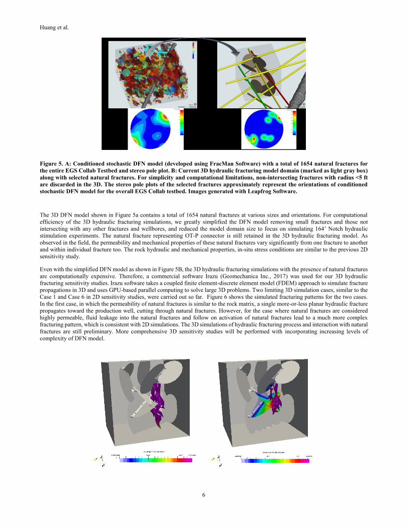
Figure 5. A: Conditioned stochastic DFN model (developed using FracMan Software) with a total of 1654 natural fractures for
the entire EGS Collab Testbed and stereo pole plot. B: Current 3D hydraulic fracturing model domain (marked as light gray box)
along with selected natural fractures. For simplicity and computational limitations, non-intersecting fractures with radius <5 ft
are discarded in the 3D. The stereo pole plots of the selected fractures approximately represent the orientations of conditioned
stochastic DFN model for the overall EGS Collab testbed. Images generated with Leapfrog Software.
The 3D DFN model shown in Figure 5a contains a total of 1654 natural fractures at various sizes and orientations. For computational
efficiency of the 3D hydraulic fracturing simulations, we greatly simplified the DFN model removing small fractures and those not
intersecting with any other fractures and wellbores, and reduced the model domain size to focus on simulating 164’ Notch hydraulic
stimulation experiments. The natural fracture representing OT-P connector is still retained in the 3D hydraulic fracturing model. As
observed in the field, the permeability and mechanical properties of these natural fractures vary significantly from one fracture to another
and within individual fracture too. The rock hydraulic and mechanical properties, in-situ stress conditions are similar to the previous 2D
sensitivity study.
Even with the simplified DFN model as shown in Figure 5B, the 3D hydraulic fracturing simulations with the presence of natural fractures
are computationally expensive. Therefore, a commercial software Irazu (Geomechanica Inc., 2017) was used for our 3D hydraulic
fracturing sensitivity studies. Irazu software takes a coupled finite element-discrete element model (FDEM) approach to simulate fracture
propagations in 3D and uses GPU-based parallel computing to solve large 3D problems. Two limiting 3D simulation cases, similar to the
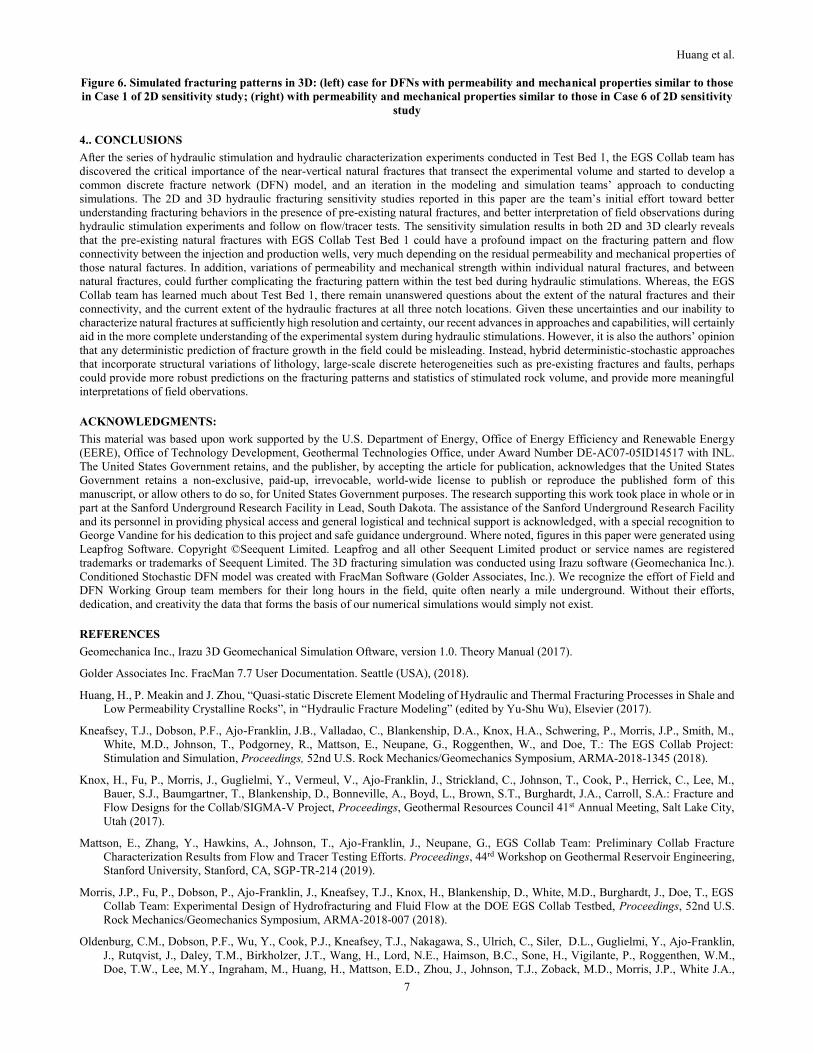
Case 1 and Case 6 in 2D sensitivity studies, were carried out so far. Figure 6 shows the simulated fracturing patterns for the two cases.
In the first case, in which the permeability of natural fractures is similar to the rock matrix, a single more-or-less planar hydraulic fracture
propagates toward the production well, cutting through natural fractures. However, for the case where natural fractures are considered
highly permeable, fluid leakage into the natural fractures and follow on activation of natural fractures lead to a much more complex
fracturing pattern, which is consistent with 2D simulations. The 3D simulations of hydraulic fracturing process and interaction with natural
fractures are still preliminary. More comprehensive 3D sensitivity studies will be performed with incorporating increasing levels of
complexity of DFN model.
Huang et al.
7
Figure 6. Simulated fracturing patterns in 3D: (left) case for DFNs with permeability and mechanical properties similar to those
in Case 1 of 2D sensitivity study; (right) with permeability and mechanical properties similar to those in Case 6 of 2D sensitivity
study
4.. CONCLUSIONS
After the series of hydraulic stimulation and hydraulic characterization experiments conducted in Test Bed 1, the EGS Collab team has
discovered the critical importance of the near-vertical natural fractures that transect the experimental volume and started to develop a
common discrete fracture network (DFN) model, and an iteration in the modeling and simulation teams’ approach to conducting
simulations. The 2D and 3D hydraulic fracturing sensitivity studies reported in this paper are the team’s initial effort toward better
understanding fracturing behaviors in the presence of pre-existing natural fractures, and better interpretation of field observations during
hydraulic stimulation experiments and follow on flow/tracer tests. The sensitivity simulation results in both 2D and 3D clearly reveals
that the pre-existing natural fractures with EGS Collab Test Bed 1 could have a profound impact on the fracturing pattern and flow
connectivity between the injection and production wells, very much depending on the residual permeability and mechanical properties of
those natural factures. In addition, variations of permeability and mechanical strength within individual natural fractures, and between
natural fractures, could further complicating the fracturing pattern within the test bed during hydraulic stimulations. Whereas, the EGS
Collab team has learned much about Test Bed 1, there remain unanswered questions about the extent of the natural fractures and their
connectivity, and the current extent of the hydraulic fractures at all three notch locations. Given these uncertainties and our inability to
characterize natural fractures at sufficiently high resolution and certainty, our recent advances in approaches and capabilities, will certainly
aid in the more complete understanding of the experimental system during hydraulic stimulations. However, it is also the authors’ opinion
that any deterministic prediction of fracture growth in the field could be misleading. Instead, hybrid deterministic-stochastic approaches
that incorporate structural variations of lithology, large-scale discrete heterogeneities such as pre-existing fractures and faults, perhaps
could provide more robust predictions on the fracturing patterns and statistics of stimulated rock volume, and provide more meaningful
interpretations of field obervations.
ACKNOWLEDGMENTS:
This material was based upon work supported by the U.S. Department of Energy, Office of Energy Efficiency and Renewable Energy
(EERE), Office of Technology Development, Geothermal Technologies Office, under Award Number DE-AC07-05ID14517 with INL.
The United States Government retains, and the publisher, by accepting the article for publication, acknowledges that the United States
Government retains a non-exclusive, paid-up, irrevocable, world-wide license to publish or reproduce the published form of this
manuscript, or allow others to do so, for United States Government purposes. The research supporting this work took place in whole or in
part at the Sanford Underground Research Facility in Lead, South Dakota. The assistance of the Sanford Underground Research Facility
and its personnel in providing physical access and general logistical and technical support is acknowledged, with a special recognition to
George Vandine for his dedication to this project and safe guidance underground. Where noted, figures in this paper were generated using
Leapfrog Software. Copyright ©Seequent Limited. Leapfrog and all other Seequent Limited product or service names are registered
trademarks or trademarks of Seequent Limited. The 3D fracturing simulation was conducted using Irazu software (Geomechanica Inc.).
Conditioned Stochastic DFN model was created with FracMan Software (Golder Associates, Inc.). We recognize the effort of Field and
DFN Working Group team members for their long hours in the field, quite often nearly a mile underground. Without their efforts,
dedication, and creativity the data that forms the basis of our numerical simulations would simply not exist.
REFERENCES
Geomechanica Inc., Irazu 3D Geomechanical Simulation Oftware, version 1.0. Theory Manual (2017).
Golder Associates Inc. FracMan 7.7 User Documentation. Seattle (USA), (2018).
Huang, H., P. Meakin and J. Zhou, “Quasi-static Discrete Element Modeling of Hydraulic and Thermal Fracturing Processes in Shale and
Low Permeability Crystalline Rocks”, in “Hydraulic Fracture Modeling” (edited by Yu-Shu Wu), Elsevier (2017).
Kneafsey, T.J., Dobson, P.F., Ajo-Franklin, J.B., Valladao, C., Blankenship, D.A., Knox, H.A., Schwering, P., Morris, J.P., Smith, M.,
White, M.D., Johnson, T., Podgorney, R., Mattson, E., Neupane, G., Roggenthen, W., and Doe, T.: The EGS Collab Project:
Stimulation and Simulation, Proceedings, 52nd U.S. Rock Mechanics/Geomechanics Symposium, ARMA-2018-1345 (2018).
Knox, H., Fu, P., Morris, J., Guglielmi, Y., Vermeul, V., Ajo-Franklin, J., Strickland, C., Johnson, T., Cook, P., Herrick, C., Lee, M.,
Bauer, S.J., Baumgartner, T., Blankenship, D., Bonneville, A., Boyd, L., Brown, S.T., Burghardt, J.A., Carroll, S.A.: Fracture and
Flow Designs for the Collab/SIGMA-V Project, Proceedings, Geothermal Resources Council 41st Annual Meeting, Salt Lake City,
Utah (2017).
Mattson, E., Zhang, Y., Hawkins, A., Johnson, T., Ajo-Franklin, J., Neupane, G., EGS Collab Team: Preliminary Collab Fracture
Characterization Results from Flow and Tracer Testing Efforts. Proceedings, 44rd Workshop on Geothermal Reservoir Engineering,
Stanford University, Stanford, CA, SGP-TR-214 (2019).
Morris, J.P., Fu, P., Dobson, P., Ajo-Franklin, J., Kneafsey, T.J., Knox, H., Blankenship, D., White, M.D., Burghardt, J., Doe, T., EGS
Collab Team: Experimental Design of Hydrofracturing and Fluid Flow at the DOE EGS Collab Testbed, Proceedings, 52nd U.S.
Rock Mechanics/Geomechanics Symposium, ARMA-2018-007 (2018).
Oldenburg, C.M., Dobson, P.F., Wu, Y., Cook, P.J., Kneafsey, T.J., Nakagawa, S., Ulrich, C., Siler, D.L., Guglielmi, Y., Ajo-Franklin,
J., Rutqvist, J., Daley, T.M., Birkholzer, J.T., Wang, H., Lord, N.E., Haimson, B.C., Sone, H., Vigilante, P., Roggenthen, W.M.,
Doe, T.W., Lee, M.Y., Ingraham, M., Huang, H., Mattson, E.D., Zhou, J., Johnson, T.J., Zoback, M.D., Morris, J.P., White J.A.,
Huang et al.
8
Johnson, P.A., Coblentz, D.D., and Heise, J..: Intermediate-Scale Hydraulic Fracturing in a Deep Mine, kISMET Project Summary
2016, LBNL-1006444, Lawrence Berkeley National Laboratory, Berkeley, CA (2016).
U.S. Department of Energy: EGS Collab. https://www.energy.gov/eere/geothermal/egs-collab (2017).
White, M.D., Fu, P., Huang, H., Ghassemi, A., EGS Collab Team: The Role of Numerical Simulation in the Design of Stimulation and
Circulation Experiments for the EGS Collab Project, Proceedings, GRC Transactions, Vol. 41 (2017).
White, M.D., Fu, P., Ghassemi, A., Huang, H., Rutqvist, J., Johnston, B., EGS Collab Team: Numerical Simulation Applications in the
Design of EGS Collab Experiment 1, PROCEEDINGS, 44th Workshop on Geothermal Reservoir Engineering, Stanford University,
Stanford, CA (2018).
White, M., Johnson, T., Kneafsey, T., Blankenship, D., Fu, P., Wu, H., Ghassemi, A., Lu, J., Huang, H., Neupane, G., Oldenburg, C.,
Doughty, C., Johnston, B., Winterfeld, P., Pollyea, R., Jayne, R., Hawkins, A., Zhang, Y., and EGS Collab Team: The Necessity for
Iteration in the Application of Numerical Simulation to EGS: Examples from the EGS Collab Test Bed 1. Proceedings, 44th
Workshop on Geothermal Reservoir Engineering Stanford University, Stanford, CA, SGP-TR-214 (2019).
Zhou, J., H. Huang, J. McLennan, P. Meakin, M. Deo (2017), A Dual-Lattice Discrete Element Model to Understand Hydraulic Fracturing
in Naturally Fractured System, Hydraulic Fracturing Journal, 4(2).