Embed Size (px)
Citation preview
Mechanisms of penetration in polyethylene reinforced cross-plylaminatesM.R. O’Masta a,*, D.H. Crayton a, V.S. Deshpande b, H.N.G. Wadley a
a Department of Material Science & Engineering, School of Engineering and Applied Science, University of Virginia, Charlottesville, VA 22904, USAb Engineering Department, Cambridge University, Trumpington Street, Cambridge CB2 1PZ, UK
A R T I C L E I N F O
Article history:Received 1 April 2015Received in revised form 14 June 2015Accepted 20 August 2015Available online 28 August 2015
Keywords:BallisticsPolymeric compositesPenetration mechanismsHybrid laminates
A B S T R A C T
The mechanisms of progressive penetration for two ultrahigh molecular weight polyethylene (UHMWPE)reinforced laminates have been investigated. One used an UHMWPE fiber reinforcement while the otherutilized molecularly aligned tape. Both materials had similar out of plane compressive strengths, but thefiber system had a 40% higher in plane tensile strength than the tape. Laminated, 6 mm thick plates witha [0°/90°] ply architecture were impacted by a 12.7 mm diameter sphere under conditions that eitherallowed out of plane plate deflection or eliminated this deflection by rear support of the target. The depthof penetration and the ballistic limit in the rear-supported tests were identical for the two materials, andproceeded by progressive ply failure. However, tests in the edge clamped condition resulted in a sub-stantially higher penetration resistance, especially for the higher tensile strength fiber-reinforced material.Edge clamped testing of a bilayer target, where the front third was composed of the tape material andthe remainder comprised fiber reinforced laminate, had the same ballistic limit as a target composed ofonly the higher ply tensile strength fiber reinforced material. Penetration in both test support condi-tions was discovered to occur by tensile ply rupture under the projectile, consistent with a recently proposedmechanism for converting out of plane compression to in plane ply tension. Lateral displacement of plieswas also observed near the sides of impact craters in both materials, indicating the existence of a secondmechanism impeding penetration of the spherical shaped projectile.
© 2015 Elsevier Ltd. All rights reserved.
1. Introduction
It is well known that composite laminates comprising high tensilestrength polymeric reinforcements and compliant polymer matri-ces possess very high ballistic penetration resistances whenconfigured in a [0°/90°] cross-ply architecture [1,2]. However, themechanisms by which an impacting projectile momentum andkinetic energy are dissipated during penetration are much less wellunderstood, and are the focus of the study reported here. The re-sponse to transverse (out of plane) impact of a thin laminate hasbeen analyzed by analogy with that of a single fiber [3–5]. The centralimpact of a single, end clamped fiber generates strain pulses thatpropagate away from the impact site. The fastest of these elastic dis-turbances travels along the fibers at the fiber longitudinal wavespeed,
cL = +( )λ μ ρ2 (1)
where λ and μ are Lamé constants and ρ the density of the fiber[6]. A shear wave with a lower velocity cH = μ ρ travels behindthe longitudinal disturbance, enabling the fiber to undergo trans-verse deflection in the direction of projectile motion. The analogouswave speeds in a composite laminate are governed by the stiff-ness constants of the laminate, and are therefore orientationdependent [7]. For a [0°/90°] cross-ply lay-up, they are highest inthe fiber directions, giving rise to a ‘pyramid shaped’ transverse de-flection envelope during impact, Fig. 1a, whose base width expandswith time.
Using dimensional analysis, Cunniff [1] showed that the ballis-tic limit of a fiber scales with the product of its longitudinal wavespeed and the strain energy per unit mass needed to fail a fiber intension. This combination of material properties gives rise to a Cuniffvelocity:
Ω = ( ) ( )⎡⎣ ⎤⎦E f f fρ σ ε ρ1 2 1 32 (2)
where Ef, σf and εf are Young’s modulus, tensile strength and failurestrain of a linear elastic fiber and ρ its density. A comprehensivecompilation of the predicted Cunniff velocities of most high per-formance fibers has been given in Ref. 8 and indicates that ultra-high molecular weight polyethylene (UHMWPE) fibers should have
* Corresponding author. Department of Material Science & Engineering, Schoolof Engineering and Applied Science, University of Virginia, Charlottesville, VA 22904,USA. Tel.: +14349825670; Fax: +14349825677.
E-mail address: [email protected] (M.R. O’Masta).
http://dx.doi.org/10.1016/j.ijimpeng.2015.08.0120734-743X/© 2015 Elsevier Ltd. All rights reserved.
International Journal of Impact Engineering 86 (2015) 249–264
Contents lists available at ScienceDirect
International Journal of Impact Engineering
journal homepage: www.elsevier.com/ locate / i j impeng
a very high ballistic limit. However, this approach provides littleinsight into the mechanisms of penetration of [0°/90°] laminatedcomposites constructed from such fibers.
Phoenix and Porwall [4] analyzed the deflection of an impact-ed laminate in the thin membrane limit where the transversedeflection of the laminate was governed by (tensile) membranestresses supported by the fibers within the laminate. In this limit,the fiber stress is independent of depth, and laminate perforationoccurs when the membrane stress attains the ply tensile strength.All else being equal, laminates with higher ply tensile strengths willhave a greater resistance to perforation. While the ballistic limit pre-dictions of the Phoenix and Porwall membrane stretching modelare consistent with the dimensional analysis of Cunniff [1], failurewas treated as a binary process; the laminate was either undam-aged or fully penetrated by an impacting projectile. No partialpenetration is permitted by such an analysis. However, numerousexperiments have shown that UHWMPE fiber reinforced lami-nates fail progressively, with a depth of penetration that increaseswith impact velocity [8–13].
A study by Heisserer [11] using HB261 grade Dyneema® showedthe depth of penetration by a hard spherical projectile increasedlinearly with projectile kinetic energy. Recent studies by Karthikeyanand Russell [13] using a spherical projectile and by Nguyen et al.[14] using fragment simulating projectiles (FSP) confirmed the ex-istence of progressive penetration before the laminate ballistic limitwas attained. All these studies indicate the penetration of these ma-terials occurs in two stages schematically illustrated in Fig. 1b.
The first “progressive” stage of penetration occurs early during theimpact process. It is accompanied by minimal transverse deflec-tion of the failed plies. The second corresponds to the out of planedeflection of the unpenetrated remainder of the laminate by a mem-brane stretching mechanism which results in fiber pull-in in the 0°and 90° fiber directions (converting a square sided panel into a pincushion shape). Karthikeyan and Russell [13] estimated the secondstage dissipated ~6.5 times more kinetic energy per perforated plythan that of the progressive penetration stage. Efforts to impede theprogressive mode of penetration, forcing failure by the secondmembrane-stretching mode are therefore likely to result in sub-stantial improvements to the ballistic resistance of these compositematerials.
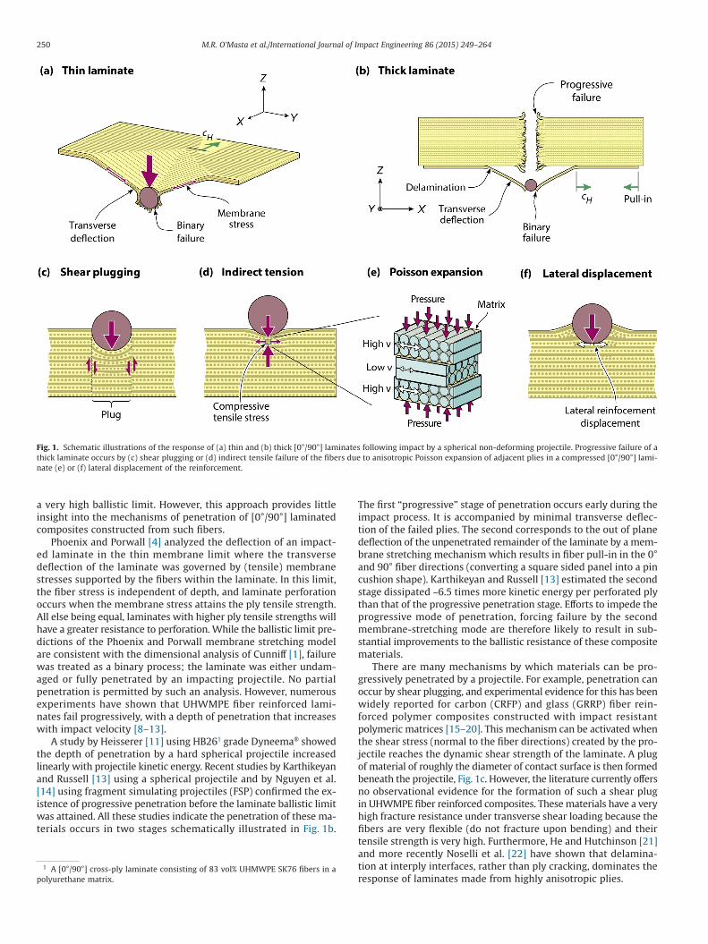
There are many mechanisms by which materials can be pro-gressively penetrated by a projectile. For example, penetration canoccur by shear plugging, and experimental evidence for this has beenwidely reported for carbon (CRFP) and glass (GRRP) fiber rein-forced polymer composites constructed with impact resistantpolymeric matrices [15–20]. This mechanism can be activated whenthe shear stress (normal to the fiber directions) created by the pro-jectile reaches the dynamic shear strength of the laminate. A plugof material of roughly the diameter of contact surface is then formedbeneath the projectile, Fig. 1c. However, the literature currently offersno observational evidence for the formation of such a shear plugin UHWMPE fiber reinforced composites. These materials have a veryhigh fracture resistance under transverse shear loading because thefibers are very flexible (do not fracture upon bending) and theirtensile strength is very high. Furthermore, He and Hutchinson [21]and more recently Noselli et al. [22] have shown that delamina-tion at interply interfaces, rather than ply cracking, dominates theresponse of laminates made from highly anisotropic plies.
1 A [0°/90°] cross-ply laminate consisting of 83 vol% UHMWPE SK76 fibers in apolyurethane matrix.
Fig. 1. Schematic illustrations of the response of (a) thin and (b) thick [0°/90°] laminates following impact by a spherical non-deforming projectile. Progressive failure of athick laminate occurs by (c) shear plugging or (d) indirect tensile failure of the fibers due to anisotropic Poisson expansion of adjacent plies in a compressed [0°/90°] lami-nate (e) or (f) lateral displacement of the reinforcement.
250 M.R. O’Masta et al./International Journal of Impact Engineering 86 (2015) 249–264
Recent experiments suggest an alternative mechanism governsthe progressive phase of penetration. Indirect evidence from impactexperiments indicated that reduction of the pressure imposed bya projectile on a laminate improves the resistance to progressivepenetration [8,12,23,24]. Furthermore, quasi-static studies haveshown that [0°/90°] laminates uniformly compressed normal to theplane of the fibers fail by tensile fiber (and ply) failure [25–27].Attwood et al. [25] showed how this counter-intuitive phenome-non can arise if the plastic Poisson expansion of a compressed plytransverse to the fiber direction is much greater than that parallelto the fibers, Fig. 1e. A transfer of stress occurs from an expandingpair of 0° plies to the 90° ply located between them. This shear lagloading mechanism then places the 90° ply in tension in the fiberdirection (while the expansion of the 90° ply also loads the 0° plyin tension). As compression of the laminate progresses, the tensilestrength of the ply is eventually reached and sudden fracture occurs.The compressive strength therefore directly depends on the plytensile strength and inter-laminar shear strength [25,26].
Other mechanisms could also be activated. For example, undersome situations lateral displacement of material away from the noseof the projectile, analogous to ductile hole enlargement [28,29], couldoccur. In the ductile materials in which hole enlargement occurs,the radial stress from the penetrating projectile plastically dis-places material, leaving a cavity in the wake of the projectile. This‘slip’ of material around a projectile has been frequently observedin dry woven composites made from UHWMPE and aramid fibers[30], but is retarded if the fibers are embedded in a resin with highshear strength resistance.
One way to test the significance of the indirect tension progres-sive penetration mechanism is to construct laminates from materialswith similar out-of-plane compressive strengths, but with differ-ent tensile strengths. It is noted that UHMWPE tapes [31,32],manufactured under the trade names Tensylon® by DuPont and morerecently grade BT10 Dyneema® by DSM, offer a means to comparelaminates with similar compressive strengths but with different plytensile strengths. Even though the tensile strength of the tape ma-terials is substantially less than that of the fiber-based materials,their out of plane compressive strengths are similar to the fiber basedgrades of these materials. Additional insights can be gained by sub-jecting panels of the two materials to impacts under conditions thateither permit or inhibit the membrane stretching response. A simplemeans for this is to place the laminate on a solid foundation so itcannot be displaced in the out-of-plane direction required to acti-vate membrane stretching [9]. The study presented here shows thatthe depth of (progressive) penetration and ballistic limit of the fiberand tape-based laminates are similar when membrane stretchingis prevented. The study then investigates the edge clamped impactresponse of the two laminates, and a bilayer target composed of bothmaterials, and reveals the presence of the same progressive pen-etration mode observed in the rear supported condition.
2. Materials and properties
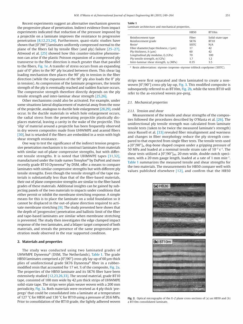
The study was conducted using two laminated grades ofUHWMPE Dyneema® (DSM, The Netherlands), Table 1. The gradeHB50 laminates comprised a [0°/90°] cross-ply lay-up of 60 μm thickplies of unidirectional grade SK76 Dyneema® fiber in a rubber-modified resin that accounted for 17 wt. % of the composite, Fig. 2a.The properties of the HB50 laminate and its SK76 fiber have beenextensively studied [12,23,26,33]. The second material, grade BT10tape, consisted of 100 mm wide by 42 μm thick strips of UHWMPEsolid-state tape. The strips were plain weave woven with a 200 mmperiodicity, Fig. 3a. Both materials were received as 4 ply thick ‘pre-pregs’ that could be consolidated into a laminate at a temperatureof 127 °C for HB50 and 130 °C for BT10 using a pressure of 20.6 MPa.Prior to consolidation of the BT10 grade, the lightly adhered woven
strips were first separated and then laminated to create a non-woven [0°/90°] cross-ply lay-up, Fig. 3. This modified composite issubsequently referred to as BT10m, Fig. 2b, while the term BT10 willrefer to the as-received woven pre-preg.
2.1. Mechanical properties
2.1.1. Tension and shearMeasurement of the tensile and shear strengths of the compos-
ites followed the procedures described by O’Masta et al. [26]. Theunidirectional ply tensile strength was calculated from laminatetensile tests (taken to be twice the measured laminate’s strength)since Russell et al. [33] revealed fiber misalignment and wavinessand changes in fiber morphology reduce the ply strength com-pared to that expected from single fiber tests. The tensile tests useda [0°/90°]4, dog-bone shaped coupon under a gripping pressure of50 MPa and loaded at a nominal tensile strain rate of 10−3 s−1. Theshear tests utilized a [0°/90°]40, 20 mm wide, double-notch speci-men, with a 20 mm gauge length, loaded at a rate of 1 mm min−1.Table 1 summarizes the measured tensile and shear strengths forthe two materials. The measurements for HB50 compare well withvalues published elsewhere [12], and confirm that the HB50
Table 1Laminate architecture and mechanical properties.
HB50 BT10m
Reinforcement type Fiber Solid-state tapeReinforcement grade SK76 BT10Resina SISTC N/AFiber diameter/tape thickness, t (μm) 17 42Ply thickness, h (μm) 60 42Longitudinal ply modulus, Ef (GPa) 70 100Ply tensile strength, σf (GPa) 1.7 1.2Inter-laminar shear strength, τ0 (MPa) 0.35 3.5
a Resin abbreviation: styrene–isoprene–styrene triblock copolymer (SISTC).
Fig. 2. Optical micrographs of the X–Z plane cross-sections of (a) an HB50 and (b)a BT10m consolidated laminate.
251M.R. O’Masta et al./International Journal of Impact Engineering 86 (2015) 249–264
laminate has a 40% higher tensile strength than BT10, but only atenth of the BT10 laminate shear strength.
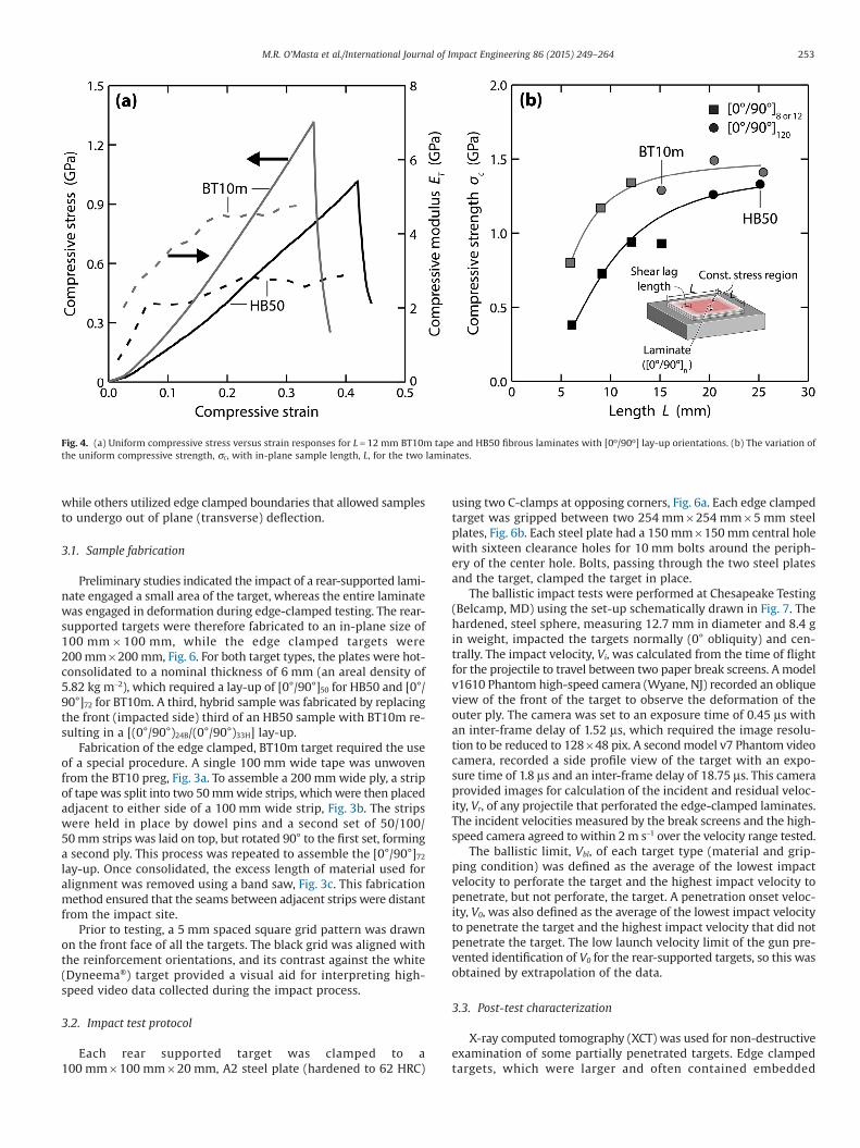
2.1.2. Uniform compression strengthWhen cross-ply [0°/90°] laminates are placed under out of plane
uniform compression, the anisotropic expansion between neigh-boring plies creates internal tensile stresses by a shear-lag mechanism[25]. The stress increases from zero at the edge of a sample to a con-stant stress over the shear lag length (inset of Fig. 4b). Therefore,the effective compressive strength increases with the in-plane lengthof the sample, L, approaching a plateau strength governed by theply tensile strength as the shear lag length becomes small com-pared to that of the sample. However, the plateau strength of thinlaminates can be reduced by the presence of missing fiber defectsin fiber reinforced Dyneema® [24].
Six 1 mm thick samples (consisting of 16 HB50 plies and 24BT10m plies) with L = 6–15 mm and two others with L = 20 and25 mm that were 240 plies thick were prepared from both mate-rials. Representative compressive stress–strain curves of HB50 andBT10m samples are plotted in Fig. 4a together with their tangentmodulus. The stress for both grades monotonically increased withstrain, with the tangent modulus of the BT10m sample being ap-proximately twice that of HB50. The samples catastrophically failedat a peak strength, σc. The compressive strength, obtained by av-eraging test results from five specimens of each material and samplelength combination, are plotted in Fig. 4b. The strength of both ma-terials monotonically increased with L as expected. However, theBT10m laminate had a higher compressive strength than HB50despite its lower ply tensile strength. This is attributed in part to asmaller shear lag length for BT10m and to less efficient conver-sion of compressive stress into tension of the reinforcement, as a
consequence of the low plastic shear resistance of HB50 [25]. This(fortuitous) difference in response to compression loading resultsin the two materials having a similar compressive strengths in thelarge L-limit (a 6% difference at L = 25mm), but markedly differenttensile strengths.
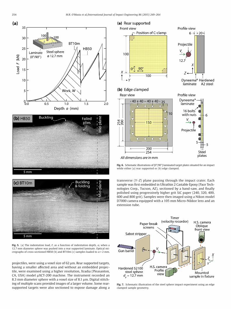
2.1.3. Punch penetrationThe quasi-static punch resistance of each laminate was inves-
tigated with the sphere used subsequently for the impact study. Ahardened, 52100 chrome-steel sphere (CCR Products LLC, West Hart-ford, CT), measuring 12.7 mm in diameter, centrally loaded a100 mm × 100 mm × 6 mm laminated panel placed on a hard-ened, A2 steel plate, at a displacement rate of 20 mm min−1, Fig. 5a.For HB50, the load, F, monotonically increased with depth of pen-etration, α, reaching a peak load of 25 kN, Fig. 5a. Attainment of thepeak load coincided with a highly unstable failure event, similar tothat observed during uniform compression, and was accompa-nied by a large drop in load. This load-to-failure sequence wasrepeated with continued penetration. Fig. 5a shows that the BT10mpanels exhibited a similar response to penetration and failed at thesame peak load, consistent with the uniform compression study.Cross-sectioned HB50 and BT10m samples after 2 mm of penetra-tion are shown in Fig. 5b and c, respectively.
3. Impact study
The penetration behavior during impact of both HB50 and BT10mgrade laminates and hybrid samples made up of both grades wasinvestigated using the hardened steel sphere. Some tests were per-formed with the laminates back-supported on a hard foundation
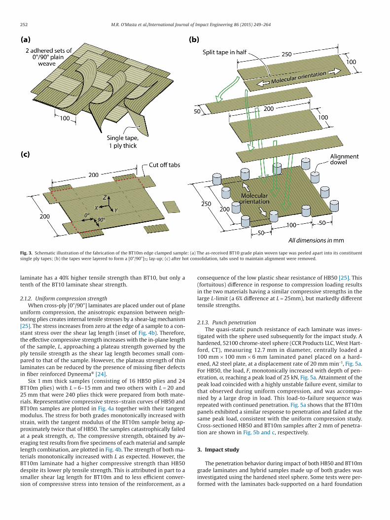
Fig. 3. Schematic illustration of the fabrication of the BT10m edge clamped sample: (a) The as-received BT10 grade plain woven tape was peeled apart into its constituentsingle ply tapes; (b) the tapes were layered to form a [0°/90°]72 lay-up; (c) after hot consolidation, tabs used to maintain alignment were removed.
252 M.R. O’Masta et al./International Journal of Impact Engineering 86 (2015) 249–264
while others utilized edge clamped boundaries that allowed samplesto undergo out of plane (transverse) deflection.
3.1. Sample fabrication
Preliminary studies indicated the impact of a rear-supported lami-nate engaged a small area of the target, whereas the entire laminatewas engaged in deformation during edge-clamped testing. The rear-supported targets were therefore fabricated to an in-plane size of100 mm × 100 mm, while the edge clamped targets were200 mm × 200 mm, Fig. 6. For both target types, the plates were hot-consolidated to a nominal thickness of 6 mm (an areal density of5.82 kg m−2), which required a lay-up of [0°/90°]50 for HB50 and [0°/90°]72 for BT10m. A third, hybrid sample was fabricated by replacingthe front (impacted side) third of an HB50 sample with BT10m re-sulting in a [(0°/90°)24B/(0°/90°)33H] lay-up.
Fabrication of the edge clamped, BT10m target required the useof a special procedure. A single 100 mm wide tape was unwovenfrom the BT10 preg, Fig. 3a. To assemble a 200 mm wide ply, a stripof tape was split into two 50 mm wide strips, which were then placedadjacent to either side of a 100 mm wide strip, Fig. 3b. The stripswere held in place by dowel pins and a second set of 50/100/50 mm strips was laid on top, but rotated 90° to the first set, forminga second ply. This process was repeated to assemble the [0°/90°]72
lay-up. Once consolidated, the excess length of material used foralignment was removed using a band saw, Fig. 3c. This fabricationmethod ensured that the seams between adjacent strips were distantfrom the impact site.
Prior to testing, a 5 mm spaced square grid pattern was drawnon the front face of all the targets. The black grid was aligned withthe reinforcement orientations, and its contrast against the white(Dyneema®) target provided a visual aid for interpreting high-speed video data collected during the impact process.
3.2. Impact test protocol
Each rear supported target was clamped to a100 mm × 100 mm × 20 mm, A2 steel plate (hardened to 62 HRC)
using two C-clamps at opposing corners, Fig. 6a. Each edge clampedtarget was gripped between two 254 mm × 254 mm × 5 mm steelplates, Fig. 6b. Each steel plate had a 150 mm × 150 mm central holewith sixteen clearance holes for 10 mm bolts around the periph-ery of the center hole. Bolts, passing through the two steel platesand the target, clamped the target in place.
The ballistic impact tests were performed at Chesapeake Testing(Belcamp, MD) using the set-up schematically drawn in Fig. 7. Thehardened, steel sphere, measuring 12.7 mm in diameter and 8.4 gin weight, impacted the targets normally (0° obliquity) and cen-trally. The impact velocity, Vi, was calculated from the time of flightfor the projectile to travel between two paper break screens. A modelv1610 Phantom high-speed camera (Wyane, NJ) recorded an obliqueview of the front of the target to observe the deformation of theouter ply. The camera was set to an exposure time of 0.45 μs withan inter-frame delay of 1.52 μs, which required the image resolu-tion to be reduced to 128 × 48 pix. A second model v7 Phantom videocamera, recorded a side profile view of the target with an expo-sure time of 1.8 μs and an inter-frame delay of 18.75 μs. This cameraprovided images for calculation of the incident and residual veloc-ity, Vr, of any projectile that perforated the edge-clamped laminates.The incident velocities measured by the break screens and the high-speed camera agreed to within 2 m s−1 over the velocity range tested.
The ballistic limit, Vbl, of each target type (material and grip-ping condition) was defined as the average of the lowest impactvelocity to perforate the target and the highest impact velocity topenetrate, but not perforate, the target. A penetration onset veloc-ity, V0, was also defined as the average of the lowest impact velocityto penetrate the target and the highest impact velocity that did notpenetrate the target. The low launch velocity limit of the gun pre-vented identification of V0 for the rear-supported targets, so this wasobtained by extrapolation of the data.
3.3. Post-test characterization
X-ray computed tomography (XCT) was used for non-destructiveexamination of some partially penetrated targets. Edge clampedtargets, which were larger and often contained embedded
Fig. 4. (a) Uniform compressive stress versus strain responses for L = 12 mm BT10m tape and HB50 fibrous laminates with [0o/90o] lay-up orientations. (b) The variation ofthe uniform compressive strength, σc, with in-plane sample length, L, for the two laminates.
253M.R. O’Masta et al./International Journal of Impact Engineering 86 (2015) 249–264
projectiles, were using a voxel size of 62 μm. Rear supported targets,having a smaller affected area and without an embedded projec-tile, were examined using a higher resolution, Xradia (Pleasanton,CA, USA) model μXCT-200 machine. The instrument recorded an8.3 mm diameter sphere with a voxel size of 8.1 μm. Digital stitch-ing of multiple scans provided images of a larger volume. Some rear-supported targets were also sectioned to expose damage along a
transverse (Y–Z) plane passing through the impact crater. Eachsample was first embedded in Ultrathin 2 Castable Epoxy (Pace Tech-nologies Corp., Tucson, AZ), sectioned by a band-saw, and finallypolished using progressively higher grit SiC paper (240, 320, 400,600 and 800 grit). Samples were then imaged using a Nikon modelD7000 camera equipped with a 105 mm Micro-Nikkor lens and anextension tube.
Fig. 5. (a) The indentation load, F, as a function of indentation depth, α, when a12.7 mm diameter sphere was pushed into a rear supported laminate. Optical mi-crographs of cross-sectioned HB50 (b) and BT10m (c) samples loaded to α ≈ 2 mm.
Fig. 6. Schematic illustrations of [0°/90°] laminated target plates situated for an impactwhile either (a) rear supported or (b) edge clamped.
Fig. 7. Schematic illustration of the steel sphere impact experiment using an edgeclamped sample geometry.
254 M.R. O’Masta et al./International Journal of Impact Engineering 86 (2015) 249–264
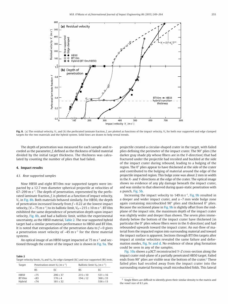
The depth of penetration was measured for each sample and re-corded as the parameter, f, defined as the thickness of failed materialdivided by the initial target thickness. The thickness was calcu-lated by counting the number of plies that had failed.
4. Impact results
4.1. Rear supported samples
Nine HB50 and eight BT10m rear supported targets were im-pacted by a 12.7 mm diameter spherical projectile at velocities of67–299 m s−1. The depth of penetration, represented by the perfo-rated laminate fraction, f, is plotted as a function of impact velocity,Vi, in Fig. 8b. Both materials behaved similarly. For HB50, the depthof penetration increased linearly from f = 0.22 at the lowest impactvelocity, (Vi = 75 m s−1) to its ballistic limit, Vbl = 215 ± 10 m s−1. BT10mexhibited the same dependence of penetration depth upon impactvelocity, Fig. 8b, and had a ballistic limit, within the experimentaluncertainty, as the HB50 material, Table 2. The rear supported hybridtarget had a similar penetration performance to HB50 and BT10m.It is noted that extrapolation of the penetration data to f = 0 givesa penetration onset velocity of ~45 m s−1 for the three materialsystems.
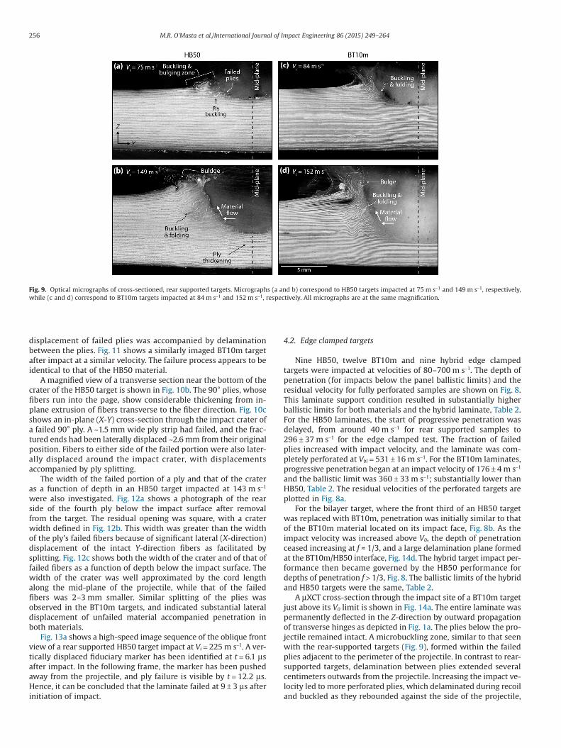
An optical image of an HB50 target impacted at 75 m s−1 and sec-tioned through the center of the impact site is shown in Fig. 9a. The
projectile created a circular-shaped crater in the target, with failedplies defining the perimeter of the impact crater. The 90° plies (thedarker gray shade ply whose fibers are in the Y-direction) that hadfractured under the projectile had recoiled and buckled at the sideof the impact crater during rebound, leading to a bulging of theregion. The 0° plies appear to have thickened at the side of the craterand contributed to the bulging of material around the edge of theprojectile impacted region. This bulge zone was about 2 mm in widthin the X- and Y-directions at the edge of the crater. The optical imageshows no evidence of any ply damage beneath the impact crater,and was similar to that observed during quasi-static penetration witha punch, Fig. 5b.
Increasing the impact velocity to 149 m s−1, Fig. 9b resulted ina deeper and wider impact crater, and a ~7 mm wide bulge zoneagain containing microbuckled 90° plies and thickened 0° plies.Because the sectioned plane in Fig. 9b is slightly offset from the mid-plane of the impact site, the maximum depth of the impact craterwas slightly wider and deeper than shown. The seven plies imme-diately below the bottom of the impact crater have thickened (inparticular the 0° plies whose fibers were in the X-direction) and hadrebounded upwards toward the impact crater. An out-flow of ma-terial from the impacted region into surrounding material and towardthe impact surface is apparent. Sections through BT10m targets afterimpact at similar velocities revealed the same failure and defor-mation modes, Fig. 9c and d. No evidence of shear plug formationcould be seen in any of the samples.
Fig. 10a shows a μXCT reconstructed Y–Z cross-section along theimpact crater mid-plane of a partially penetrated HB50 target. Failedends from 90° plies are visible near the bottom of the crater.2 Thesefailed plies had recoiled away from the impact crater into thesurrounding material forming small microbuckled folds. This lateral
2 Single fibers are difficult to identify given their similar density to the matrix andthe voxel size of 8.1 μm.
Fig. 8. (a) The residual velocity, Vr, and (b) the perforated laminate fraction, f, are plotted as functions of the impact velocity, Vi, for both rear supported and edge clampedtargets for the two materials and the hybrid system. Solid lines are drawn to help reveal trends.
Table 2Target velocity limits, V0 and Vbl, for edge clamped (EC) and rear supported (RS) tests.
Target Penetration onset V0 (m s−1) Ballistic limit Vbl (m s−1)
RS EC RS EC
HB50 <75 296 ± 37 215 ± 10 531 ± 16BT10m <83 176 ± 4 194 ± 12 360 ± 33Hybrid <74 181 ± 32 – 536 ± 13
255M.R. O’Masta et al./International Journal of Impact Engineering 86 (2015) 249–264
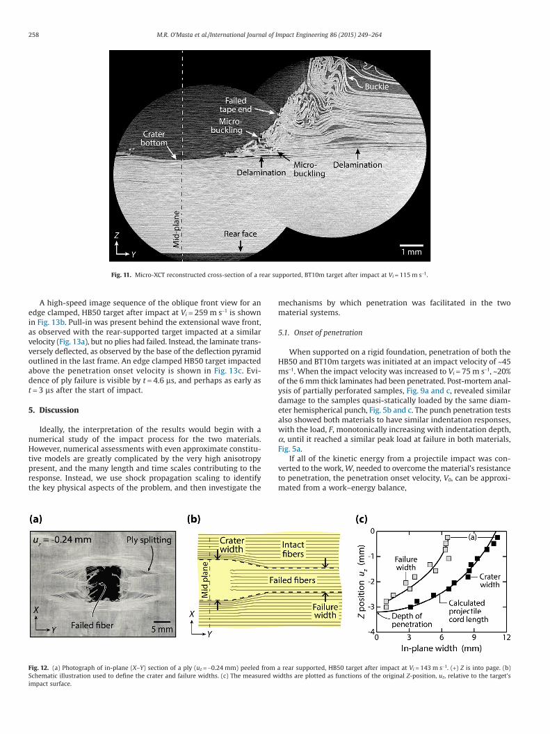
displacement of failed plies was accompanied by delaminationbetween the plies. Fig. 11 shows a similarly imaged BT10m targetafter impact at a similar velocity. The failure process appears to beidentical to that of the HB50 material.
A magnified view of a transverse section near the bottom of thecrater of the HB50 target is shown in Fig. 10b. The 90° plies, whosefibers run into the page, show considerable thickening from in-plane extrusion of fibers transverse to the fiber direction. Fig. 10cshows an in-plane (X-Y) cross-section through the impact crater ofa failed 90° ply. A ~1.5 mm wide ply strip had failed, and the frac-tured ends had been laterally displaced ~2.6 mm from their originalposition. Fibers to either side of the failed portion were also later-ally displaced around the impact crater, with displacementsaccompanied by ply splitting.
The width of the failed portion of a ply and that of the crateras a function of depth in an HB50 target impacted at 143 m s−1
were also investigated. Fig. 12a shows a photograph of the rearside of the fourth ply below the impact surface after removalfrom the target. The residual opening was square, with a craterwidth defined in Fig. 12b. This width was greater than the widthof the ply’s failed fibers because of significant lateral (X-direction)displacement of the intact Y-direction fibers as facilitated bysplitting. Fig. 12c shows both the width of the crater and of that offailed fibers as a function of depth below the impact surface. Thewidth of the crater was well approximated by the cord lengthalong the mid-plane of the projectile, while that of the failedfibers was 2–3 mm smaller. Similar splitting of the plies wasobserved in the BT10m targets, and indicated substantial lateraldisplacement of unfailed material accompanied penetration inboth materials.
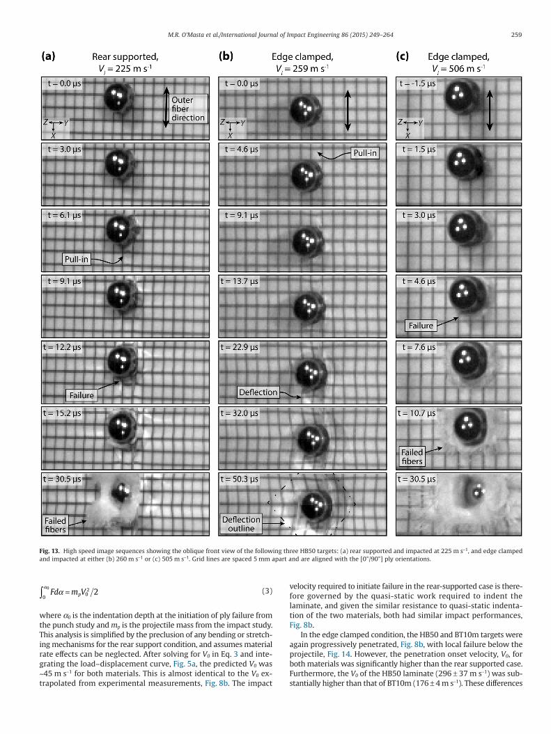
Fig. 13a shows a high-speed image sequence of the oblique frontview of a rear supported HB50 target impact at Vi = 225 m s−1. A ver-tically displaced fiduciary marker has been identified at t = 6.1 μsafter impact. In the following frame, the marker has been pushedaway from the projectile, and ply failure is visible by t = 12.2 μs.Hence, it can be concluded that the laminate failed at 9 ± 3 μs afterinitiation of impact.
4.2. Edge clamped targets
Nine HB50, twelve BT10m and nine hybrid edge clampedtargets were impacted at velocities of 80–700 m s−1. The depth ofpenetration (for impacts below the panel ballistic limits) and theresidual velocity for fully perforated samples are shown on Fig. 8.This laminate support condition resulted in substantially higherballistic limits for both materials and the hybrid laminate, Table 2.For the HB50 laminates, the start of progressive penetration wasdelayed, from around 40 m s−1 for rear supported samples to296 ± 37 m s−1 for the edge clamped test. The fraction of failedplies increased with impact velocity, and the laminate was com-pletely perforated at Vbl = 531 ± 16 m s−1. For the BT10m laminates,progressive penetration began at an impact velocity of 176 ± 4 m s−1
and the ballistic limit was 360 ± 33 m s−1; substantially lower thanHB50, Table 2. The residual velocities of the perforated targets areplotted in Fig. 8a.
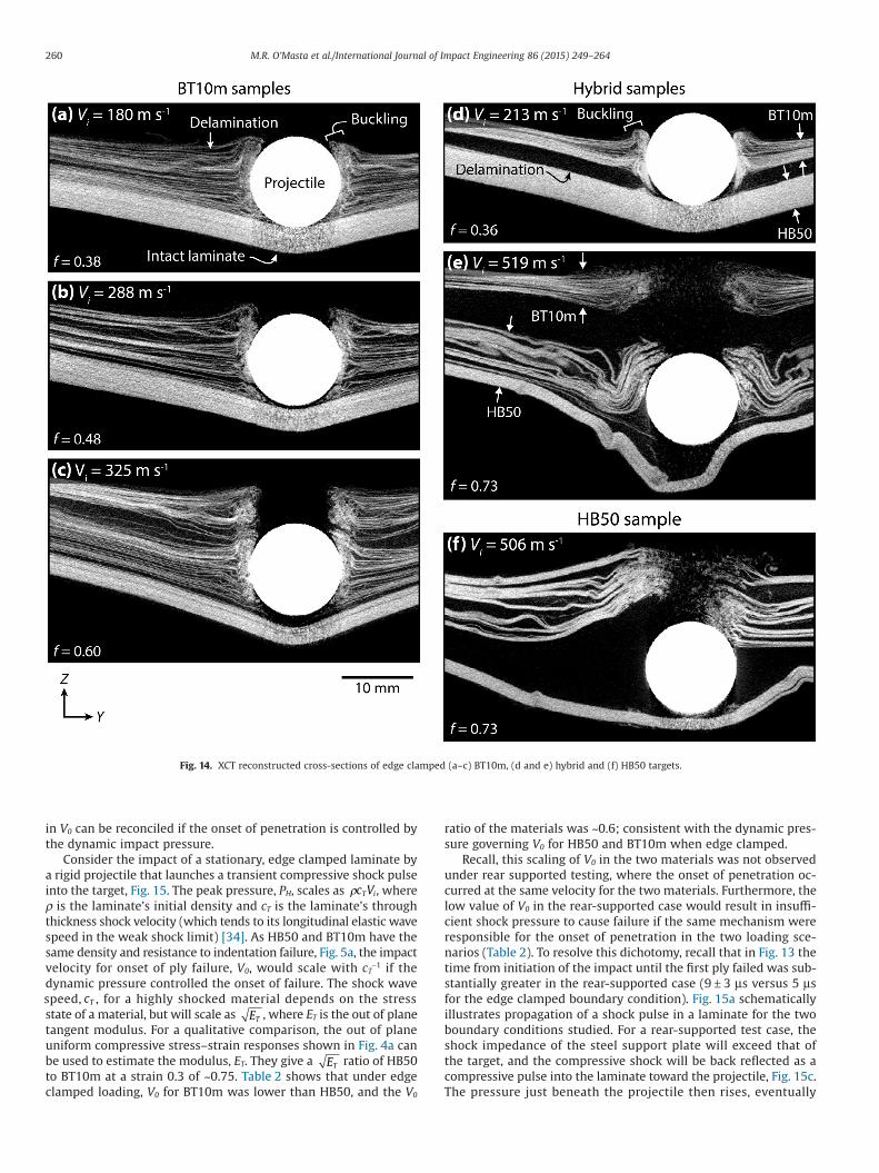
For the bilayer target, where the front third of an HB50 targetwas replaced with BT10m, penetration was initially similar to thatof the BT10m material located on its impact face, Fig. 8b. As theimpact velocity was increased above V0, the depth of penetrationceased increasing at f ≈ 1/3, and a large delamination plane formedat the BT10m/HB50 interface, Fig. 14d. The hybrid target impact per-formance then became governed by the HB50 performance fordepths of penetration f > 1/3, Fig. 8. The ballistic limits of the hybridand HB50 targets were the same, Table 2.
A μXCT cross-section through the impact site of a BT10m targetjust above its V0 limit is shown in Fig. 14a. The entire laminate waspermanently deflected in the Z-direction by outward propagationof transverse hinges as depicted in Fig. 1a. The plies below the pro-jectile remained intact. A microbuckling zone, similar to that seenwith the rear-supported targets (Fig. 9), formed within the failedplies adjacent to the perimeter of the projectile. In contrast to rear-supported targets, delamination between plies extended severalcentimeters outwards from the projectile. Increasing the impact ve-locity led to more perforated plies, which delaminated during recoiland buckled as they rebounded against the side of the projectile,
Fig. 9. Optical micrographs of cross-sectioned, rear supported targets. Micrographs (a and b) correspond to HB50 targets impacted at 75 m s−1 and 149 m s−1, respectively,while (c and d) correspond to BT10m targets impacted at 84 m s−1 and 152 m s−1, respectively. All micrographs are at the same magnification.
256 M.R. O’Masta et al./International Journal of Impact Engineering 86 (2015) 249–264
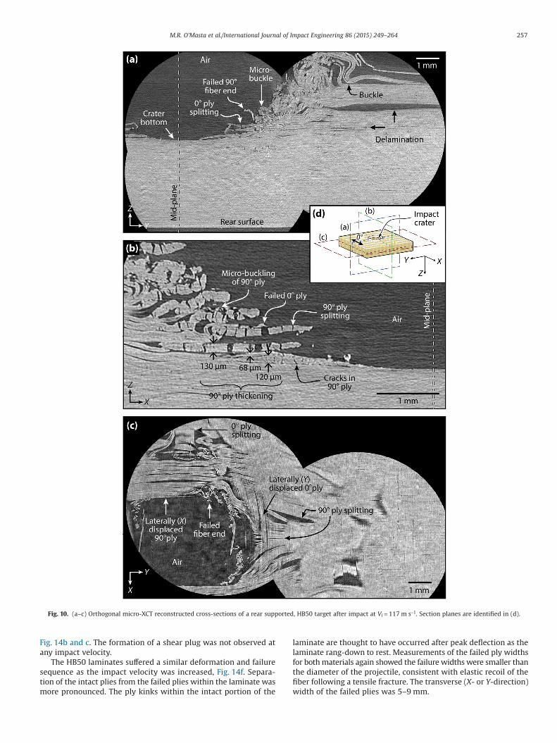
Fig. 14b and c. The formation of a shear plug was not observed atany impact velocity.
The HB50 laminates suffered a similar deformation and failuresequence as the impact velocity was increased, Fig. 14f. Separa-tion of the intact plies from the failed plies within the laminate wasmore pronounced. The ply kinks within the intact portion of the
laminate are thought to have occurred after peak deflection as thelaminate rang-down to rest. Measurements of the failed ply widthsfor both materials again showed the failure widths were smaller thanthe diameter of the projectile, consistent with elastic recoil of thefiber following a tensile fracture. The transverse (X- or Y-direction)width of the failed plies was 5–9 mm.
Fig. 10. (a–c) Orthogonal micro-XCT reconstructed cross-sections of a rear supported, HB50 target after impact at Vi = 117 m s−1. Section planes are identified in (d).
257M.R. O’Masta et al./International Journal of Impact Engineering 86 (2015) 249–264
A high-speed image sequence of the oblique front view for anedge clamped, HB50 target after impact at Vi = 259 m s−1 is shownin Fig. 13b. Pull-in was present behind the extensional wave front,as observed with the rear-supported target impacted at a similarvelocity (Fig. 13a), but no plies had failed. Instead, the laminate trans-versely deflected, as observed by the base of the deflection pyramidoutlined in the last frame. An edge clamped HB50 target impactedabove the penetration onset velocity is shown in Fig. 13c. Evi-dence of ply failure is visible by t = 4.6 μs, and perhaps as early ast = 3 μs after the start of impact.
5. Discussion
Ideally, the interpretation of the results would begin with anumerical study of the impact process for the two materials.However, numerical assessments with even approximate constitu-tive models are greatly complicated by the very high anisotropypresent, and the many length and time scales contributing to theresponse. Instead, we use shock propagation scaling to identifythe key physical aspects of the problem, and then investigate the
mechanisms by which penetration was facilitated in the twomaterial systems.
5.1. Onset of penetration
When supported on a rigid foundation, penetration of both theHB50 and BT10m targets was initiated at an impact velocity of ~45ms−1. When the impact velocity was increased to Vi = 75 m s−1, ~20%of the 6 mm thick laminates had been penetrated. Post-mortem anal-ysis of partially perforated samples, Fig. 9a and c, revealed similardamage to the samples quasi-statically loaded by the same diam-eter hemispherical punch, Fig. 5b and c. The punch penetration testsalso showed both materials to have similar indentation responses,with the load, F, monotonically increasing with indentation depth,α, until it reached a similar peak load at failure in both materials,Fig. 5a.
If all of the kinetic energy from a projectile impact was con-verted to the work, W, needed to overcome the material’s resistanceto penetration, the penetration onset velocity, V0, can be approxi-mated from a work–energy balance,
Fig. 11. Micro-XCT reconstructed cross-section of a rear supported, BT10m target after impact at Vi = 115 m s−1.
Fig. 12. (a) Photograph of in-plane (X–Y) section of a ply (uz = −0.24 mm) peeled from a rear supported, HB50 target after impact at Vi = 143 m s−1. (+) Z is into page. (b)Schematic illustration used to define the crater and failure widths. (c) The measured widths are plotted as functions of the original Z-position, uz, relative to the target’simpact surface.
258 M.R. O’Masta et al./International Journal of Impact Engineering 86 (2015) 249–264
Fd m Vpαα
0020
2∫ = (3)
where α0 is the indentation depth at the initiation of ply failure fromthe punch study and mp is the projectile mass from the impact study.This analysis is simplified by the preclusion of any bending or stretch-ing mechanisms for the rear support condition, and assumes materialrate effects can be neglected. After solving for V0 in Eq. 3 and inte-grating the load–displacement curve, Fig. 5a, the predicted V0 was~45 m s−1 for both materials. This is almost identical to the V0 ex-trapolated from experimental measurements, Fig. 8b. The impact
velocity required to initiate failure in the rear-supported case is there-fore governed by the quasi-static work required to indent thelaminate, and given the similar resistance to quasi-static indenta-tion of the two materials, both had similar impact performances,Fig. 8b.
In the edge clamped condition, the HB50 and BT10m targets wereagain progressively penetrated, Fig. 8b, with local failure below theprojectile, Fig. 14. However, the penetration onset velocity, V0, forboth materials was significantly higher than the rear supported case.Furthermore, the V0 of the HB50 laminate (296 ± 37 m s−1) was sub-stantially higher than that of BT10m (176 ± 4 m s−1). These differences
Fig. 13. High speed image sequences showing the oblique front view of the following three HB50 targets: (a) rear supported and impacted at 225 m s−1, and edge clampedand impacted at either (b) 260 m s−1 or (c) 505 m s−1. Grid lines are spaced 5 mm apart and are aligned with the [0°/90°] ply orientations.
259M.R. O’Masta et al./International Journal of Impact Engineering 86 (2015) 249–264
in V0 can be reconciled if the onset of penetration is controlled bythe dynamic impact pressure.
Consider the impact of a stationary, edge clamped laminate bya rigid projectile that launches a transient compressive shock pulseinto the target, Fig. 15. The peak pressure, PH, scales as ρc VT i, whereρ is the laminate’s initial density and cT is the laminate’s throughthickness shock velocity (which tends to its longitudinal elastic wavespeed in the weak shock limit) [34]. As HB50 and BT10m have thesame density and resistance to indentation failure, Fig. 5a, the impactvelocity for onset of ply failure, V0, would scale with cT
−1 if thedynamic pressure controlled the onset of failure. The shock wavespeed, cT , for a highly shocked material depends on the stressstate of a material, but will scale as ET , where ET is the out of planetangent modulus. For a qualitative comparison, the out of planeuniform compressive stress–strain responses shown in Fig. 4a canbe used to estimate the modulus, ET. They give a ET ratio of HB50to BT10m at a strain 0.3 of ~0.75. Table 2 shows that under edgeclamped loading, V0 for BT10m was lower than HB50, and the V0
ratio of the materials was ~0.6; consistent with the dynamic pres-sure governing V0 for HB50 and BT10m when edge clamped.
Recall, this scaling of V0 in the two materials was not observedunder rear supported testing, where the onset of penetration oc-curred at the same velocity for the two materials. Furthermore, thelow value of V0 in the rear-supported case would result in insuffi-cient shock pressure to cause failure if the same mechanism wereresponsible for the onset of penetration in the two loading sce-narios (Table 2). To resolve this dichotomy, recall that in Fig. 13 thetime from initiation of the impact until the first ply failed was sub-stantially greater in the rear-supported case (9 ± 3 μs versus 5 μsfor the edge clamped boundary condition). Fig. 15a schematicallyillustrates propagation of a shock pulse in a laminate for the twoboundary conditions studied. For a rear-supported test case, theshock impedance of the steel support plate will exceed that ofthe target, and the compressive shock will be back reflected as acompressive pulse into the laminate toward the projectile, Fig. 15c.The pressure just beneath the projectile then rises, eventually
Fig. 14. XCT reconstructed cross-sections of edge clamped (a–c) BT10m, (d and e) hybrid and (f) HB50 targets.
260 M.R. O’Masta et al./International Journal of Impact Engineering 86 (2015) 249–264
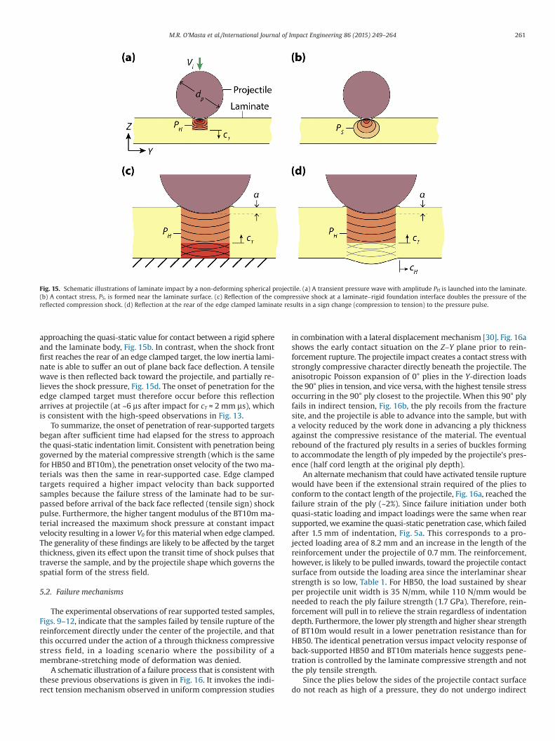
approaching the quasi-static value for contact between a rigid sphereand the laminate body, Fig. 15b. In contrast, when the shock frontfirst reaches the rear of an edge clamped target, the low inertia lami-nate is able to suffer an out of plane back face deflection. A tensilewave is then reflected back toward the projectile, and partially re-lieves the shock pressure, Fig. 15d. The onset of penetration for theedge clamped target must therefore occur before this reflectionarrives at projectile (at ~6 μs after impact for cT ≈ 2 mm μs), whichis consistent with the high-speed observations in Fig. 13.
To summarize, the onset of penetration of rear-supported targetsbegan after sufficient time had elapsed for the stress to approachthe quasi-static indentation limit. Consistent with penetration beinggoverned by the material compressive strength (which is the samefor HB50 and BT10m), the penetration onset velocity of the two ma-terials was then the same in rear-supported case. Edge clampedtargets required a higher impact velocity than back supportedsamples because the failure stress of the laminate had to be sur-passed before arrival of the back face reflected (tensile sign) shockpulse. Furthermore, the higher tangent modulus of the BT10m ma-terial increased the maximum shock pressure at constant impactvelocity resulting in a lower V0 for this material when edge clamped.The generality of these findings are likely to be affected by the targetthickness, given its effect upon the transit time of shock pulses thattraverse the sample, and by the projectile shape which governs thespatial form of the stress field.
5.2. Failure mechanisms
The experimental observations of rear supported tested samples,Figs. 9–12, indicate that the samples failed by tensile rupture of thereinforcement directly under the center of the projectile, and thatthis occurred under the action of a through thickness compressivestress field, in a loading scenario where the possibility of amembrane-stretching mode of deformation was denied.
A schematic illustration of a failure process that is consistent withthese previous observations is given in Fig. 16. It invokes the indi-rect tension mechanism observed in uniform compression studies
in combination with a lateral displacement mechanism [30]. Fig. 16ashows the early contact situation on the Z–Y plane prior to rein-forcement rupture. The projectile impact creates a contact stress withstrongly compressive character directly beneath the projectile. Theanisotropic Poisson expansion of 0° plies in the Y-direction loadsthe 90° plies in tension, and vice versa, with the highest tensile stressoccurring in the 90° ply closest to the projectile. When this 90° plyfails in indirect tension, Fig. 16b, the ply recoils from the fracturesite, and the projectile is able to advance into the sample, but witha velocity reduced by the work done in advancing a ply thicknessagainst the compressive resistance of the material. The eventualrebound of the fractured ply results in a series of buckles formingto accommodate the length of ply impeded by the projectile’s pres-ence (half cord length at the original ply depth).
An alternate mechanism that could have activated tensile rupturewould have been if the extensional strain required of the plies toconform to the contact length of the projectile, Fig. 16a, reached thefailure strain of the ply (~2%). Since failure initiation under bothquasi-static loading and impact loadings were the same when rearsupported, we examine the quasi-static penetration case, which failedafter 1.5 mm of indentation, Fig. 5a. This corresponds to a pro-jected loading area of 8.2 mm and an increase in the length of thereinforcement under the projectile of 0.7 mm. The reinforcement,however, is likely to be pulled inwards, toward the projectile contactsurface from outside the loading area since the interlaminar shearstrength is so low, Table 1. For HB50, the load sustained by shearper projectile unit width is 35 N/mm, while 110 N/mm would beneeded to reach the ply failure strength (1.7 GPa). Therefore, rein-forcement will pull in to relieve the strain regardless of indentationdepth. Furthermore, the lower ply strength and higher shear strengthof BT10m would result in a lower penetration resistance than forHB50. The identical penetration versus impact velocity response ofback-supported HB50 and BT10m materials hence suggests pene-tration is controlled by the laminate compressive strength and notthe ply tensile strength.
Since the plies below the sides of the projectile contact surfacedo not reach as high of a pressure, they do not undergo indirect
Fig. 15. Schematic illustrations of laminate impact by a non-deforming spherical projectile. (a) A transient pressure wave with amplitude PH is launched into the laminate.(b) A contact stress, PS, is formed near the laminate surface. (c) Reflection of the compressive shock at a laminate–rigid foundation interface doubles the pressure of thereflected compression shock. (d) Reflection at the rear of the edge clamped laminate results in a sign change (compression to tension) to the pressure pulse.
261M.R. O’Masta et al./International Journal of Impact Engineering 86 (2015) 249–264
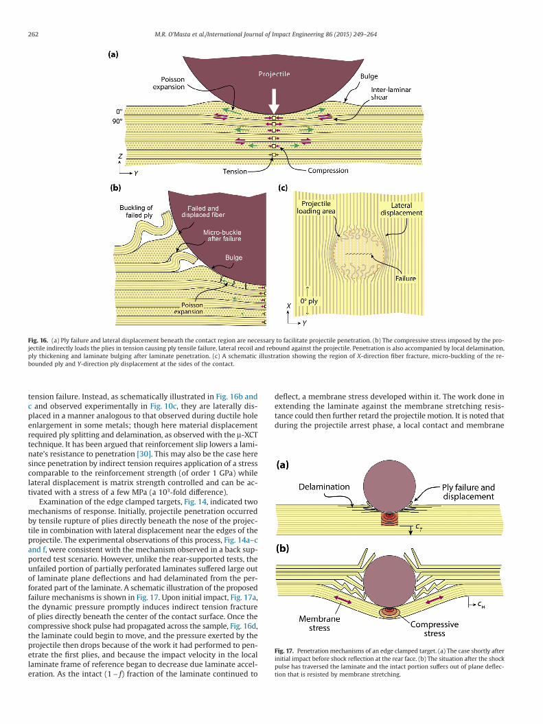
tension failure. Instead, as schematically illustrated in Fig. 16b andc and observed experimentally in Fig. 10c, they are laterally dis-placed in a manner analogous to that observed during ductile holeenlargement in some metals; though here material displacementrequired ply splitting and delamination, as observed with the μ-XCTtechnique. It has been argued that reinforcement slip lowers a lami-nate’s resistance to penetration [30]. This may also be the case heresince penetration by indirect tension requires application of a stresscomparable to the reinforcement strength (of order 1 GPa) whilelateral displacement is matrix strength controlled and can be ac-tivated with a stress of a few MPa (a 103-fold difference).
Examination of the edge clamped targets, Fig. 14, indicated twomechanisms of response. Initially, projectile penetration occurredby tensile rupture of plies directly beneath the nose of the projec-tile in combination with lateral displacement near the edges of theprojectile. The experimental observations of this process, Fig. 14a–cand f, were consistent with the mechanism observed in a back sup-ported test scenario. However, unlike the rear-supported tests, theunfailed portion of partially perforated laminates suffered large outof laminate plane deflections and had delaminated from the per-forated part of the laminate. A schematic illustration of the proposedfailure mechanisms is shown in Fig. 17. Upon initial impact, Fig. 17a,the dynamic pressure promptly induces indirect tension fractureof plies directly beneath the center of the contact surface. Once thecompressive shock pulse had propagated across the sample, Fig. 16d,the laminate could begin to move, and the pressure exerted by theprojectile then drops because of the work it had performed to pen-etrate the first plies, and because the impact velocity in the locallaminate frame of reference began to decrease due laminate accel-eration. As the intact (1 − f) fraction of the laminate continued to
deflect, a membrane stress developed within it. The work done inextending the laminate against the membrane stretching resis-tance could then further retard the projectile motion. It is noted thatduring the projectile arrest phase, a local contact and membrane
Fig. 16. (a) Ply failure and lateral displacement beneath the contact region are necessary to facilitate projectile penetration. (b) The compressive stress imposed by the pro-jectile indirectly loads the plies in tension causing ply tensile failure, lateral recoil and rebound against the projectile. Penetration is also accompanied by local delamination,ply thickening and laminate bulging after laminate penetration. (c) A schematic illustration showing the region of X-direction fiber fracture, micro-buckling of the re-bounded ply and Y-direction ply displacement at the sides of the contact.
Fig. 17. Penetration mechanisms of an edge clamped target. (a) The case shortly afterinitial impact before shock reflection at the rear face. (b) The situation after the shockpulse has traversed the laminate and the intact portion suffers out of plane deflec-tion that is resisted by membrane stretching.
262 M.R. O’Masta et al./International Journal of Impact Engineering 86 (2015) 249–264
stress exist, and the combined stress may have enabled additionalpenetration during laminate deflection, Fig. 17b.
The edge clamped hybrid target, with the front third of the targetthickness consisting of BT10m and the remainder HB50, had thesame ply perforation onset velocity, V0, as BT10m, Fig. 8b. This isconsistent with V0 being governed by the dynamic impact pres-sure. After penetrating the BT10m portion of the hybrid, the depthof penetration followed the same dependence with impact veloc-ity as the higher performance HB50 target. These results suggestthat a benefit may exist to a multi-material composite lamination,and several groups have investigated multi-material composite con-cepts [35–39]. The present study suggests the placement of plieswith the lowest impedance and the greatest resistance to indirecttension (compressive strength) nearest the impact side, where de-flection is minimal, would be beneficial. The higher tensile strengthplies would be placed nearest the rear side of a laminate to sustainhigher membrane stresses. It is also interesting to note that for someprojectile nose geometries, use of a material with too weak of aninter-laminar shear strength may result in low ballistic resistancewith failure dominated by lateral ply displacement.
6. Concluding remarks
An investigation of the deformation and fracture mechanismsthat accommodate progressive projectile penetration of [0°/90°]UHMWPE reinforced plastic composites has been performed. Thestudy exploited differences in the response of HB50 fiber- and BT10tape-reinforced grades of Dyneema®. The HB50 and BT10m lami-nates had similar transverse (out-of-plane) compressive strengths,while HB50 had a 40% higher ply tensile strength. Ballistic targets,measuring 6 mm in thickness, were made from each material as wellas from a bilayer hybrid, where the front third of the thickness wasBT10m. The impact of each target by a 12.7 mm diameter, hard-ened (non-deforming) sphere was examined in test scenarios wherethe target was either supported on a stiff foundation to prevent trans-verse deflection or clamped along its edges to permit out of planedeflection.
When rear supported, the velocity needed to initiate penetra-tion and the dependence of the depth of penetration upon impactvelocity were the same for the two materials consistent with ma-terial compressive response governing penetration. Indirect tensionof the reinforcement and lateral displacement of material from thetip of the projectile accommodated penetration. No shear plug mech-anism was observed with either material.
When end supported, both materials had a higher penetrationonset velocity and a higher impact performance compared to theback supported test case. The velocity of penetration initiation scaledinversely with shock pulse speed (HB50 required a higher velocityto initiate ply failure than BT10m); while the ballistic limit in-creased with the tensile strength of the material. The samplesexhibited progressive failure as the impact velocity increased, andfailure was initiated rapidly before shock pulse reflections from theback face reached the region of contact. The mechanism of pro-gressive penetration was consistent with indirect tension failure incombination with lateral displacement at the sides of the projec-tile and membrane stretching of the unfailed portion of the laminate.These observations suggest future investigation of multi-material(hybrid) laminates that combine materials with highest compres-sive strength and lowest impendence near the impact site and thosewith highest tensile strength at the rear may result in significantimpact performance benefits.
Acknowledgements
We are grateful to DSM for providing the materials used in thisstudy. This research was funded by the Defense Advanced Re-
search Projects Agency (DARPA) under grant number W91CRB-11-1-0005 (Program manager, Dr. J. Goldwasser). Dyneema® is atrademark of DSM.
References
[1] Cunniff PM. Dimensionless parameters for optimization of textile-based bodyarmor systems. In: Reinecke W.G., editor. Proc. 18th Int. Symp. Ballist. SanAntonio, TX: Technomic Publishing Company, Inc; 1999. p. 1303–10.
[2] Cheeseman BA, Bogetti TA. Ballistic impact into fabric and compliant compositelaminates. Compos Struct 2003;61:161–73. doi:10.1016/S0263-8223(03)00029-1.
[3] Cunniff PM. An analysis of the system effects in woven fabrics under ballisticimpact. Text Res J 1992;62:495–509.
[4] Phoenix SL, Porwal PK. A new membrane model for the ballistic impact responseand V50 performance of multi-ply fibrous systems. Int J Solids Struct2003;40:6723–65. doi:10.1016/S0020-7683(03)00329-9.
[5] Chocron S, King N, Bigger R, Walker JD, Heisserer U, van der Werff H. Impactsand waves in Dyneema® HB80 strips and laminates. J Appl Mech2013;80:031806. doi:10.1115/1.4023349.
[6] Smith JC, Fenstermaker CA, Shouse PJ. Behavior of filamentous materialssubjected to high-speed tensile impact. Symp. Dyn. Behav. Mater. WestConshohocken, PA: ASTM International; 1963. p. 47–69.
[7] Christensen RM. Mechanics of composite materials. New York: Wiley; 1979.[8] O’Masta MR, Deshpande VS, Wadley HNG. Mechanisms of projectile penetration
in Dyneema® encapsulated aluminum structures. Int J Impact Eng 2014;74:16–35. doi:10.1016/j.ijimpeng.2014.02.002.
[9] Iremonger MJ. Polyethylene composites for protection against high velocity smallarms bullets. In: Reinecke W.G., editor. Proc. 18th Int. Symp. Ballist., San Antonio,TX: Technomic Publishing Company, Inc. 1999. p. 946–54.
[10] Greenhalgh ES, Bloodworth VM, Iannucci L, Pope D. Fractographic observationson Dyneema® composites under ballistic impact. Compos Part A Appl Sci Manuf2013;44:51–62. doi:10.1016/j.compositesa.2012.08.012.
[11] Heisserer U, van der Werff H, Hendrix J. Ballistic depth of penetration studiesin Dyneema® composites. In: Wickert M., Salk M., editors. Proc. 27th Int. Symp.Ballist, vol. 2. Freiburg: DEStech Publications, Inc.; 2013. p. 1936–43.
[12] Karthikeyan K, Russell BP, Fleck NA, Wadley HNG, Deshpande VS. The effectof shear strength on the ballistic response of laminated composite plates. EurJ Mech – A/Solids 2013;42:35–53. doi:10.1016/j.euromechsol.2013.04.002.
[13] Karthikeyan K, Russell BP. Polyethylene Ballistic Laminates: failure mechanicsand interface effect. Mater Des 2014;63:115–25. doi:10.1016/j.matdes.2014.05.069.
[14] Nguyen LH, Ryan S, Cimpoeru SJ, Mouritz AP, Orifici AC. The effect of targetthickness on the ballistic performance of ultra high molecular weightpolyethylene composite. Int J Impact Eng 2015;75:174–83. doi:10.1016/j.ijimpeng.2014.07.008.
[15] Cantwell WJ, Morton J. Impact perforation of carbon fibre reinforced plastic.Compos Sci Technol 1990;38:119–41. doi:10.1016/0266-3538(90)90002-M.
[16] Culnane AH, Woodward RL, Egglestone GT. Failure examination of compositematerials using standard metallographic techniques. J Mater Sci Lett1991;10:333–4. doi:10.1007/BF00719700.
[17] Lee S-WR, Sun CT. Dynamic penetration of graphite/epoxy laminates impactedby a blunt-ended projectile. Compos Sci Technol 1993;49:369–80. doi:10.1016/0266-3538(93)90069-S.
[18] Gama BA, Gillespie JW Jr. Punch shear based penetration model of ballisticimpact of thick-section composites. Compos Struct 2008;86:356–69.doi:10.1016/j.compstruct.2007.11.001.
[19] Gama BA, Gillespie JW Jr. Finite element modeling of impact, damage evolutionand penetration of thick-section composites. Int J Impact Eng 2011;38:181–97.doi:10.1016/j.ijimpeng.2010.11.001.
[20] Shaktivesh, Nair NS, Sesha Kumar CV, Naik NK. Ballistic impact performanceof composite targets. Mater Des 2013;51:833–46. doi:10.1016/j.matdes.2013.04.093.
[21] Ming-Yuan H, Hutchinson JW. Crack deflection at an interface betweendissimilar elastic materials. Int J Solids Struct 1989;25:1053–67. doi:10.1016/0020-7683(89)90021-8.
[22] Noselli G, Deshpande VS, Fleck NA. An analysis of competing tougheningmechanisms in layered and particulate solids. Int J Fract 2013;183:241–58.doi:10.1007/s10704-013-9890-8.
[23] Karthikeyan K, Russell BP, Fleck NA, O’Masta MR, Wadley HNG, Deshpande VS.The soft impact response of composite laminate beams. Int J Impact Eng2013;60:24–36. doi:10.1016/j.ijimpeng.2013.04.002.
[24] O’Masta MR, Compton BG, Gamble EA, Zok FW, Deshpande VS, Wadley HNG.Ballistic impact response of an UHMWPE fiber reinforced laminate encasingof an aluminum-alumina hybrid panel. Int J Impact Eng 2015;86:131–44.
[25] Attwood JP, Khaderi SN, Karthikeyan K, Fleck NA, O’Masta MR, Wadley HNG,Deshpande, VS. The out-of-plane compressive response of Dyneema®composites. J Mech Phys Solids 2014;70:200–26. doi:10.1016/j.jmps.2014.05.017.
[26] O’Masta MR, Deshpande VS, Wadley HNG. Defect controlled transversecompressive strength of polyethylene fiber laminates. Int J Solids Struct2015;52:130–49. doi:10.1016/j.ijsolstr.2014.09.023.
[27] Chocron S, Nicholls AE, Brill A, Malka A, Namir T, Havazelet D, et al. Modelingunidirectional composites by bundling fibers into strips with experimental
263M.R. O’Masta et al./International Journal of Impact Engineering 86 (2015) 249–264

determination of shear and compression properties at high pressures. ComposSci Technol 2014;101:32–40. doi:10.1016/j.compscitech.2014.06.016.
[28] Backman ME, Goldsmith W. The mechanics of penetration of projectiles intotargets. Int J Eng Sci 1978;16:1–99. doi:10.1016/0020-7225(78)90002-2.
[29] Corbett GG, Reid SR, Johnson W. Impact loading of plates and shells byfree-flying projectiles: a review. Int J Impact Eng 1996;18:141–230.doi:10.1016/0734-743X(95)00023-4.
[30] Lee BL, Walsh TF, Won ST, Patts HM, Song JW, Mayer AH. Penetration failuremechanisms of armor-grade fiber composites under impact. J Compos Mater2001;35:1605–33. doi:10.1106/YRBH-JGT9-U6PT-L555.
[31] Harding KC, Mitchell JE, Petrea WB. High modulus ultra high molecular weightpolyethylene tape. US8206810 B1, 2012.
[32] Morye SS, Hine PJ, Duckett RA, Carr DJ, Ward IM. A comparison of the propertiesof hot compacted gel-spun polyethylene fibre composites with conventionalgel-spun polyethylene fibre composites. Compos Part A Appl Sci Manuf1999;30:649–60. doi:10.1016/S1359-835X(98)00175-4.
[33] Russell BP, Karthikeyan K, Deshpande VS, Fleck NA. The high strain rate responseof Ultra High Molecular-weight Polyethylene: from fibre to laminate. Int J ImpactEng 2013;60:1–9. doi:10.1016/j.ijimpeng.2013.03.010.
[34] Ahrens TJ. Equation of state. In: Asay JR, Shahinpoor M, editors.High-press. Shock compression solids. NY: Springer-Verlag; 1993. p. 75–114.
[35] Cunniff PM. Decoupled response of textile body armor. In: Proc. 18th Int.Symp. Ballist. San Antonio, TX: Technomic Publishing Company, Inc. 1999. p.814–21.
[36] Larsson F, Svensson L. Carbon, polyethylene and PBO hybrid fibre compositesfor structural lightweight armour. Compos Part A Appl Sci Manuf 2002;33:221–31. doi:10.1016/S1359-835X(01)00095-1.
[37] Lyons FS, Mears JA, Weedon GC, Harding KC, Owen L, Russell PA, et al. Ballistic-resistant article including one or more layers of cross-plied uhmwpe tape incombination with cross-plied fibers. US7972679 B1, 2011.
[38] Lyons FS, Mears JA, Weedon GC, Harding KC, Owen L, Russell PA, et al. Ballistic-resistant panel including high modulus ultra high molecular weightpolyethylene tape. US7976932 B1, 2011.
[39] Vargas-Gonzalez L, Walsh SM, Wolbert J. Impact and ballistic response ofhybridized thermoplastic laminates. Aberdeen Proving Ground, MD: ArmyResearch Laboratory; 2011. Technical Report ARL-MR-0769.
264 M.R. O’Masta et al./International Journal of Impact Engineering 86 (2015) 249–264