Embed Size (px)
Citation preview

Mechanics of Materials 40 (2008) 812–824
Contents lists available at ScienceDirect
Mechanics of Materials
journal homepage: www.elsevier .com/locate /mechmat
Variational asymptotic micromechanics modeling of heterogeneouspiezoelectric materials
Tian Tang, Wenbin Yu *
Department of Mechanical and Aerospace Engineering, Utah State University, Logan, UT 80322-4130, USA
a r t i c l e i n f o
Article history:Received 27 September 2007Received in revised form 29 April 2008
Keywords:Piezoelectric heterogeneous materialsVariational asymptotic methodMircomechanicsVAMUCH
0167-6636/$ - see front matter � 2008 Elsevier Ltddoi:10.1016/j.mechmat.2008.04.007
* Corresponding author. Tel.: +1 435 7978246; faE-mail address: [email protected] (W. Yu).
a b s t r a c t
In this paper, a new micromechanics model is developed to predict the effective propertiesand local fields of heterogeneous piezoelectric materials using the variational asymptoticmethod for unit cell homogenization (VAMUCH), a recently developed micromechanicsmodeling technique. Starting from the total electric enthalpy of the heterogenous contin-uum, we formulate the micromechanics model as a constrained minimization problemusing the variational asymptotic method. To handle realistic microstructures in engineer-ing applications, we implement this new model using the finite element method. For val-idation, a few examples are used to demonstrate the application and accuracy of thistheory and the companion computer program – VAMUCH.
� 2008 Elsevier Ltd. All rights reserved.
1. Introduction
Piezoelectric materials such as PZT (Lead, Zirconium,Titanate) are widely used in sensors and actuators due totheir property of converting electric energy into mechani-cal energy, and vice versa. However, bulk piezoelectricmaterials have several drawbacks for instance theirweight, disadvantage of shape control, and acoustic imped-ance, therefore composite piezoelectric materials are usu-ally a better technical solution in the case of manyapplications such as ultrasonic imaging, sensors, actuatorsand damping. Recently, piezoelectric composites are devel-oped by combining piezoelectric materials with passivematerials to form a variety of types of piezoelectric com-posite systems. To facilitate the design of these piezoelec-tric composites, convenient and accurate analysis tools areapparently indispensable.
In the past several decades, numerous approaches havebeen proposed to predict the effective properties of piezo-electric composites from known constituent information.Simple analytical approaches based on Voigt or Reusshypothesis have been applied to predict the behavior of a
. All rights reserved.
x: +1 435 7972417.
limited class of composite geometries (Newnham et al.,1978; Banno, 1983; Chan and Unsworth, 1989; Smithand Auld, 1991). Variational bounds have been obtainedfor describing the complete overall behavior which areuseful tools for theoretical consideration (Bisegna andLuciano, 1996, 1997; Li and Dunn, 2001). However therange between bounds can be very large for certain effec-tive properties. Eshelby’s solutions (Eshelby, 1957) havebeen extended to include piezoelectric constituents(Wang, 1992; Benveniste, 1992; Dunn and Taya, 1993b;Chen, 1993). Such mean field-type methods are capableof predicting the entire behavior under arbitrary loads.However, they use averaged representations of the electricand mechanical field within the constituents of the com-posite, i.e., they do not account for the local fluctuationsof the field quantities. This restriction can be overcomeby a finite element method-based micromechanical analy-sis (Gaudenzi, 1997; Poizat and Sester, 1999). In such mod-els the representative unit cell and the boundaryconditions are designed to capture a few special load caseswhich are connected to specific deformation patterns. Thisallows the prediction of only a few key material parame-ters. The finite element unit cell models which can capturethe entire behavior have recently appeared (Lenglet et al.,2003; Sun et al., 2001; Pettermann and Suresh, 2000; Li,

T. Tang, W. Yu / Mechanics of Materials 40 (2008) 812–824 813
2000; Pastor, 1997; Berger et al., 2006). Other studies(Dunn and Taya, 1993a, 1994; Huang and Kuo, 1996; Fakriet al., 2003) have focused on the classical extensions ofEshelby’s solution for finite inclusion volume fractions,i.e., the Mori–Tanaka (Mori and Tanaka, 1973; Benveniste,1987) self-consistent approach (Hill, 1965; Budiansky,1965), differential approaches (McLaughlin, 1977; Norris,1985), and models based on the generalized Mori–Tanakaand self-consistent approaches (Odegard, 2004).
In this paper, a novel micromechanics model based onthe framework of variational asymptotic method for unitcell homogenization (VAMUCH) has been developed topredict the effective properties and local fields of piezo-electric composites. This model invokes two essentialassumptions within the concept of micromechanics forcomposites with an identifiable unit cell (UC):
� Assumption 1: The exact field variables have volumeaverage over the UC. For example, if ui and / are respec-tively the exact displacements and electric potentialwithin the UC, there exist vi and w such that
vi ¼1X
ZX
ui dX � huii ð1Þ
w ¼ 1X
ZX
/ d X � h/i ð2Þ
where X denotes the domain occupied by the UC and itsvolume.
� Assumption 2: The effective material properties obtainedfrom the micromechanical analysis of the UC are inde-pendent of the geometry, the boundary conditions, andloading conditions of the macroscopic structure, whichmeans that effective properties are assumed to be theintrinsic properties of the material when viewedmacroscopically.
2 ,x
0
1
2
3
Fig. 1. Coordinate systems for heterogenous materials (o
Note that these assumptions are not restrictive. Themathematical meaning of the first assumption is that theexact solutions of the field variables can be integrated overthe domain of UC, which is true almost all the time. Thesecond assumption implies that we will neglect the size ef-fects of the material properties in the macroscopic analysis,which is an assumption often made in the conventionalcontinuum mechanics. Of course, the micromechanicalanalysis of the UC is only needed and appropriate ifg ¼ h=l� 1, with h as the characteristic size of the UCand l as the characteristic wavelength of the deformationof the structure. Other assumptions such as particulargeometry shape and arrangement of the constituents, spe-cific boundary conditions applied to the UC, and prescribedrelations between local fields and global fields are not nec-essary for the present study.
This new micromechanical modeling approach has beensuccessfully used to predict the effective thermoelasticproperties including elastic constants, specific heats, andcoefficients of thermal expansions, and effectivethermal conductivity and associated local fields (Yu andTang, 2007a,b; Tang and Yu, 2007a). It is also applied toaccurately predict the initial yielding surface and elasto-plastic behavior of metal matrix composites (Tang andYu, 2007b).
2. Piezoelectricity and piezoelectric composites
The elastic and the dielectric responses are coupled inpiezoelectric materials where the mechanical variables ofstress, and strain are related to each other as well as tothe electric variables of electric field and electric displace-ment. The coupling between mechanical and electricfields is described by piezoelectric coefficients. Using the
11 , nx
2n
3 21
1, 1 2, 1
1y
2y
nly two-dimensional (2D) UC is drawn for clarity).

814 T. Tang, W. Yu / Mechanics of Materials 40 (2008) 812–824
conventional indicial notation, the linear coupled constitu-tive equations are expressed as
rij ¼ Cijkl�kl � eijkEk
Ti ¼ eikl�kl þ kijEjð3Þ
where rij, �ij, Ei and Ti are the stress tensor, strain tensor,electric field vector, and the electric displacement vector,respectively. Cijkl denotes fourth-order elasticity tensor atconstant electric field, kij is the second-order dielectrictensor at constant strain field, eijk is the third-order piezo-electric coupling tensor. To avoid the difficulty associatedwith heterogeneity, we can use the micromechanics ap-proach to homogenize the material and obtain an effectiveconstitutive model, such that
�rij ¼ C�ijkl��kl � e�ijkEk
Ti ¼ e�ijk��jk þ k�ijEj
ð4Þ
where ‘‘over-bar” means variables used in the macroscopicanalysis of homogenized materials, and superscripts ‘‘*”denote the effective properties whose calculation aredetermined by the micromechanics model one employs.
3. Theoretical formulation
VAMUCH formulation uses three coordinates systems:two cartesian coordinates x ¼ ðx1; x2; x3Þ and y¼ðy1;y2;y3Þ,and an integer-valued coordinate n ¼ ðn1;n2;n3Þ (see Fig.1). We use xi as the global coordinates to describe the mac-roscopic structure and yi parallel to xi as the local coordi-nates to describe the UC (Here and throughout the paper,Latin indices assume 1, 2, and 3 and repeated indices aresummed over their range except where explicitly indi-cated). We choose the origin of the local coordinates yi tobe the geometric center of UC. For example, if the UC is acube with dimensions as di, then yi 2 ½� di
2 ;di2 �. To uniquely
locate a UC in the heterogeneous material we also intro-duce integer coordinates ni. The integer coordinates are re-lated to the global coordinates in such a way that ni ¼ xi=di
(no summation over i). It is emphasized although onlysquare array is sketched in Fig. 1, the present theory hasno such limitations.
As implied by Assumption 2, we can obtain the sameeffective properties from an imaginary, unbounded, andunloaded heterogeneous material with the same micro-structure as the real, loaded, and bounded one. Hence wecould derive the micromechanics model from an imaginary,unloaded, heterogeneous material which completely occu-pies the three-dimensional (3D) space R and composes ofinfinite many repeating UCs. For piezoelectric composites,the total electric enthalpy is equal to the summation ofthe electric enthalpy stored in all the UCs, which is
P ¼X1
n¼�1
ZX
2H dX ð5Þ
where 2H is twice the electric enthalpy, given by
2H ¼ �T D� ð6Þ
with
� ¼ b�11;2�12; �22;2�13;2�23; �33; E1; E2; E3cT ð7Þ
containing both the 3D strain field �ij and the 3D electricfield Ei, which are defined for a linear theory as
�ijðn; yÞ ¼ 12
ouiðn; yÞoyj
þ oujðn; yÞoyi
" #ð8Þ
Eiðn; yÞ ¼ � o/ðn; yÞoyi
ð9Þ
and D is a 9� 9 matrix including the elastic, piezoelectric,and dielectric properties and is expressed as
D ¼C �e�eT �k
� �ð10Þ
In view of the fact that the infinite many UCs form a contin-uous heterogenous material, we need to enforce the conti-nuity of the displacement field ui and the electric potentialfield / on the interface between adjacent UCs, which is
uiðn1;n2;n3; d1=2; y2; y3Þ ¼ uiðn1 þ 1;n2;n3;�d1=2; y2; y3Þuiðn1;n2;n3; y1;d2=2; y3Þ ¼ uiðn1;n2 þ 1;n3; y1;�d2=2; y3Þuiðn1;n2;n3; y1; y2; d3=2Þ ¼ uiðn1;n2;n3 þ 1; y1; y2;�d3=2Þ
ð11Þ/ðn1;n2;n3; d1=2; y2; y3Þ ¼ /ðn1 þ 1;n2;n3;�d1=2; y2; y3Þ/ðn1;n2;n3; y1;d2=2; y3Þ ¼ /ðn1;n2 þ 1;n3; y1;�d2=2; y3Þ/ðn1;n2;n3; y1; y2;d3=2Þ ¼ /ðn1;n2;n3 þ 1; y1; y2;�d3=2Þ
ð12Þ
It is pointed out that the continuity of the traction and theelectric displacement is guaranteed by the variational prin-ciple if the continuity of the displacement and the electricpotential is satisfied. Of course, if the displacement and theelectric potential are solved approximately using a numer-ical technique such as the finite element method (FEM),then the continuity of the traction and the electric dis-placement will only be satisfied approximately althoughthe continuity of the displacement and the electric poten-tial can be satisfied exactly through the same nodal values.
The exact solution of the present problem will minimizethe summation of electric enthalpy in Eq. (5) under theconstraints in Eqs. (1), (2), (11), and (12). Due to discreteinteger arguments, the problem is very difficult to solve.To avoid the difficulty associated with discrete integerarguments, we can reformulate the problem, includingEqs. (5), (8), (9), (11) and (12), in terms of continuous func-tions using the idea of quasicontinuum (Kunin, 1982). Thecorresponding formulas are listed below
P ¼ZR
h�T D�idR ð13Þ
�ijðx; yÞ ¼ 12
ouiðx; yÞoyj
þ oujðx; yÞoyi
" #� uðijjÞ ð14Þ
Eiðx; yÞ ¼ � o/ðx; yÞoyi
ð15Þ
and
uiðx1; x2; x3; d1=2; y2; y3Þ ¼ uiðx1 þ d1; x2; x3;�d1=2; y2; y3Þuiðx1; x2; x3; y1; d2=2; y3Þ ¼ uiðx1; x2 þ d2; x3; y1;�d2=2; y3Þuiðx1; x2; x3; y1; y2;d3=2Þ ¼ uiðx1; x2; x3 þ d3; y1; y2;�d3=2Þ
ð16Þ

T. Tang, W. Yu / Mechanics of Materials 40 (2008) 812–824 815
/ðx1; x2; x3; d1=2; y2; y3Þ ¼ /ðx1 þ d1; x2; x3;�d1=2; y2; y3Þ/ðx1; x2; x3; y1;d2=2; y3Þ ¼ /ðx1; x2 þ d2; x3; y1;�d2=2; y3Þ/ðx1; x2; x3; y1; y2;d3=2Þ ¼ /ðx1; x2; x3 þ d3; y1; y2;�d3=2Þ
ð17ÞIntroducing Lagrange multipliers, we can pose the varia-tional statement of the micromechanical analysis of UCas a stationary value problem of the following functional:
J ¼ZR
h�T D�i þ kiðhuii � viÞ þ kðh/i � wÞ�
þZ
S1
ci1½uiðxj; d1=2; y2; y3Þ
� uiðxj þ dj1d1;�d1=2; y2; y3Þ�dS1
þZ
S2
ci2½uiðxj; y1;d2=2; y3Þ
� uiðxj þ dj2d2; y1;�d2=2; y3Þ�dS2
þZ
S3
ci3½uiðxj; y1; y2;d3=2Þ
� uiðxj þ dj3d3; y1; y2;�d3=2Þ�dS3
þZ
S1
b1½/ðxj; d1=2; y2; y3Þ
� /ðxj þ dj1d1;�d1=2; y2; y3Þ�dS1
þZ
S2
b2½/ðxj; y1;d2=2; y3Þ
� /ðxj þ dj2d2; y1;�d2=2; y3Þ�dS2
þZ
S3
b3½/ðxj; y1; y2; d3=2Þ
�/ðxj þ dj3d3; y1; y2;�d3=2Þ�dS3�
dR ð18Þ
where ki, k, cij, and bi are Lagrange multipliers introducedto enforce the constraints in Eqs. (1), (2), (16) and (17),respectively, Si are the surfaces with ni ¼ 1, xj representsthe triplet of x1; x2; x3, and dij is the Kronecker delta. Fol-lowing the general procedure of VAMUCH, we can obtainthe following change of variables for ui and /:
uiðx; yÞ ¼ viðxÞ þ yjovi
oxjþ viðx; yÞ ð19Þ
/ðx; yÞ ¼ wðxÞ þ yiowoxiþ fðx; yÞ ð20Þ
where vi and f are the fluctuation functions, satisfying thefollowing constraints in view of Eqs. (1), (19), (2), (20)when the origin of the local coordinate system is chosento be the center of UC:
hvii ¼ 0 ð21Þhfi ¼ 0 ð22Þ
Substituting Eqs. (19) and (20) into Eq. (18), we obtain astationary value problem defined over UC for vi and faccording to the variational asymptotic method (Berdi-chevsky, 1977), such that
JX ¼ h�T D�i þ kihvii þ khfi þX3
j¼1
ZSj
cijðvþji � v�j
i Þ dSj
þX3
j¼1
ZSj
bjðfþj � f�jÞ dSj ð23Þ
with
vþji ¼ vijyj¼dj=2;v
�ji ¼ vijyj¼�dj=2 for j ¼ 1;2;3
fþj ¼ fjyj¼dj=2; f�j ¼ fjyj¼�dj=2 for j ¼ 1;2;3
Matrix � can be expressed as
� ¼ ��þ �1 ð24Þ
with
�� ¼ ov1
ox1;ov1
ox2þ ov2
ox1;ov2
ox2;ov1
ox3þ ov3
ox1;ov2
ox3
�þ ov3
ox2;ov3
ox3;� ow
ox1� ow
ox2;� ow
ox3
�T
ð25Þ
which will be shown later to be the global variables con-taining both the strain field and the electric field for thematerial with homogenized effective material properties,and
�1 ¼ov1
oy1;ov1
oy2þ ov2
oy1;ov2
oy2;ov1
oy3
�þ ov3
oy1;ov2
oy3þ ov3
oy2;ov3
oy3;� of
oy1;� of
oy2;� of
oy3
�T
ð26Þ
The functional JX in Eq. (23) forms the backbone of thepresent theory. This variational statement can be solvedanalytically for very simple cases such as binary compos-ites, however, for general cases we need to use numericaltechniques such as FEM to seek numerical solutions.
4. Finite element implementation
It is possible to formulate the FEM solution based onEq. (23), however, it is not the most convenient and effi-cient way because Lagrange multipliers will increase thenumber of unknowns. To this end, we can reformulatethe variational statement in Eq. (23) as the minimum valueof the following functional
PX ¼1X
ZX�T D� dX ð27Þ
under the following constraints
vþji ¼ v�j
i and fþj ¼ f�j for j ¼ 1;2;3 ð28Þ
It is noted here that the constraints in Eq. (28) are the com-monly assumed periodic boundary conditions. However,here both Eqs. (27) and (28) are direct consequence ofEq. (23), that is the periodic boundary conditions are de-rived from the theory instead of assumed a priori. The con-straint in Eqs. (21) and (22) does not affect the minimumvalues of PX but help uniquely determine vi and f. In prac-tice, we can constrain the fluctuation function at an arbi-trary node to be zero and later use this constraint torecover the unique fluctuation function. It is fine to usepenalty function method to introduce the constraints inEq. (28). However, this method introduces additionalapproximation and the robustness of the solution dependson the choice of large penalty numbers. Instead, we makethe nodes on the positive boundary surface (i.e.,yi ¼ di=2) slave to the nodes on the opposite negativeboundary surface (i.e., yi ¼ �di=2). By assembling all the
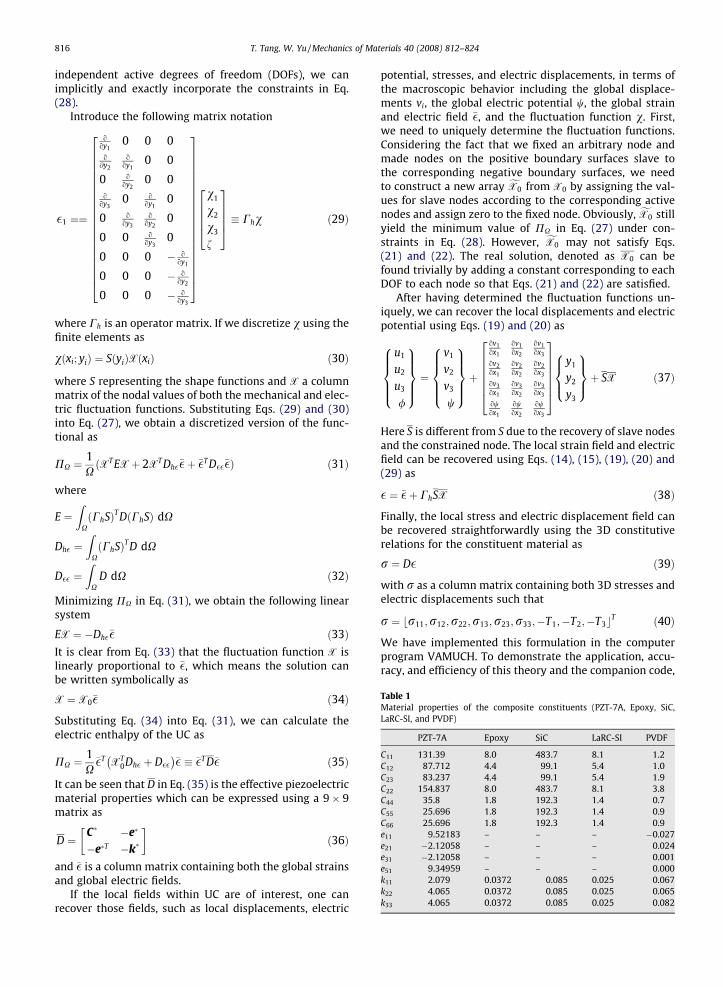
Table 1Material properties of the composite constituents (PZT-7A, Epoxy, SiC,LaRC-SI, and PVDF)
PZT-7A Epoxy SiC LaRC-SI PVDF
C11 131.39 8.0 483.7 8.1 1.2C12 87.712 4.4 99.1 5.4 1.0C23 83.237 4.4 99.1 5.4 1.9C22 154.837 8.0 483.7 8.1 3.8C44 35.8 1.8 192.3 1.4 0.7C55 25.696 1.8 192.3 1.4 0.9C66 25.696 1.8 192.3 1.4 0.9e11 9.52183 – – – �0.027e21 �2.12058 – – – 0.024e31 �2.12058 – – – 0.001e51 9.34959 – – – 0.000k11 2.079 0.0372 0.085 0.025 0.067k22 4.065 0.0372 0.085 0.025 0.065k33 4.065 0.0372 0.085 0.025 0.082
816 T. Tang, W. Yu / Mechanics of Materials 40 (2008) 812–824
independent active degrees of freedom (DOFs), we canimplicitly and exactly incorporate the constraints in Eq.(28).
Introduce the following matrix notation
�1 ¼¼
ooy1
0 0 0o@y2
ooy1
0 0
0 ooy2
0 0o
oy30 o
oy10
0 ooy3
ooy2
0
0 0 ooy3
0
0 0 0 � ooy1
0 0 0 � ooy2
0 0 0 � ooy3
266666666666666666664
377777777777777777775
v1
v2
v3
f
2666437775 � Chv ð29Þ
where Ch is an operator matrix. If we discretize v using thefinite elements as
vðxi; yiÞ ¼ SðyiÞXðxiÞ ð30Þ
where S representing the shape functions and X a columnmatrix of the nodal values of both the mechanical and elec-tric fluctuation functions. Substituting Eqs. (29) and (30)into Eq. (27), we obtain a discretized version of the func-tional as
PX ¼1XðXT EXþ 2XT Dh���þ ��T D����Þ ð31Þ
where
E ¼Z
XðChSÞT DðChSÞ dX
Dh� ¼Z
XðChSÞT D dX
D�� ¼Z
XD dX ð32Þ
Minimizing PX in Eq. (31), we obtain the following linearsystem
EX ¼ �Dh��� ð33ÞIt is clear from Eq. (33) that the fluctuation function X islinearly proportional to ��, which means the solution canbe written symbolically as
X ¼ X0�� ð34Þ
Substituting Eq. (34) into Eq. (31), we can calculate theelectric enthalpy of the UC as
PX ¼1X
��T XT0Dh� þ D��
� �� � ��T D�� ð35Þ
It can be seen that D in Eq. (35) is the effective piezoelectricmaterial properties which can be expressed using a 9� 9matrix as
D ¼C� �e�
�e�T �k�
� �ð36Þ
and �� is a column matrix containing both the global strainsand global electric fields.
If the local fields within UC are of interest, one canrecover those fields, such as local displacements, electric
potential, stresses, and electric displacements, in terms ofthe macroscopic behavior including the global displace-ments vi, the global electric potential w, the global strainand electric field ��, and the fluctuation function v. First,we need to uniquely determine the fluctuation functions.Considering the fact that we fixed an arbitrary node andmade nodes on the positive boundary surfaces slave tothe corresponding negative boundary surfaces, we needto construct a new array fX0 from X0 by assigning the val-ues for slave nodes according to the corresponding activenodes and assign zero to the fixed node. Obviously, fX0 stillyield the minimum value of PX in Eq. (27) under con-straints in Eq. (28). However, fX0 may not satisfy Eqs.(21) and (22). The real solution, denoted as X0 can befound trivially by adding a constant corresponding to eachDOF to each node so that Eqs. (21) and (22) are satisfied.
After having determined the fluctuation functions un-iquely, we can recover the local displacements and electricpotential using Eqs. (19) and (20) as
u1
u2
u3
/
8>>><>>>:9>>>=>>>; ¼
v1
v2
v3
w
8>>><>>>:9>>>=>>>;þ
ov1ox1
ov1ox2
ov1ox3
ov2ox1
ov2ox2
ov2ox3
ov3ox1
ov3ox2
ov3ox3
owox1
owox2
owox3
2666664
3777775y1
y2
y3
8><>:9>=>;þ SX ð37Þ
Here S is different from S due to the recovery of slave nodesand the constrained node. The local strain field and electricfield can be recovered using Eqs. (14), (15), (19), (20) and(29) as
� ¼ ��þ ChSX ð38Þ
Finally, the local stress and electric displacement field canbe recovered straightforwardly using the 3D constitutiverelations for the constituent material as
r ¼ D� ð39Þ
with r as a column matrix containing both 3D stresses andelectric displacements such that
r ¼ br11;r12;r22;r13;r23;r33;�T1;�T2;�T3cT ð40Þ
We have implemented this formulation in the computerprogram VAMUCH. To demonstrate the application, accu-racy, and efficiency of this theory and the companion code,

T. Tang, W. Yu / Mechanics of Materials 40 (2008) 812–824 817
we will analyze several examples using VAMUCH in thenext section.
5. Numerical examples
VAMUCH provides a unified analysis for general 1D,2D, or 3D UCs. First, the same code VAMUCH can beused to homogenize binary composites (modeled using
0
10
20
30
40
50
60
70
10 20 30 4Volume Fractio
Stif
fnes
s C
onst
ants
(GP
a)
VAMUCH-C11-SQUFEM-C11-SQUVAMUCH-C11-HEXFEM-C11-HEXVAMUCH-C22-SQUFEM-C22-SQUVAMUCH-C22-HEXFEM-C22-HEX
Fig. 2. Effective stiffness co
4
6
8
10
12
14
16
18
10 20 30 4Volume Fracti
Stiff
ness
Con
stan
ts (G
Pa)
VAMUCH-C12-SQU
FEM-C12-SQU
VAMUCH-C12-HEX
FEM-C12-HEX
VAMUCH-C23-SQU
FEM-C23-SQU
VAMUCH-C23-HEX
FEM-C23-HEX
Fig. 3. Effective stiffness co
1D UCs), fiber reinforced composites (modeled using2D UCs), and particle reinforced composites (mod-eled using 3D UCs). Second, VAMUCH can reproducethe results for lower-dimensional UCs usinghigher-dimensional UCs. That is, VAMUCH predicts thesame results for binary composites using 1D, 2D or 3DUCs, and for fiber reinforced composites using 2D or3D UCs.
0 50 60 70n of Fibers (%)
nstants C11 and C22.
0 50 60 70on of Fibers (%)
nstants C12 and C23.

0
2
4
6
8
10
12
10 20 30 40 50 60 70Volume Fraction of Fibers (%)
Stif
fnes
s C
onst
ants
(GP
a)
VAMUCH-C44-SQUFEM-C44-SQUVAMUCH-C44-HEXFEM-C44-HEXVAMUCH-C55-SQUFEM-C55-SQUVAMUCH-C55-HEXFEM-C55-HEX
Fig. 4. Effective stiffness constants C44 and C55.
-0.4
-0.3
-0.2
-0.1
0
0.1
0.2
10 20 30 40 50 60 70Volume fraction of fibers (%)
Piez
oele
ctric
cou
plin
g co
nsta
nts
(C/
)
VAMUCH-e21-SQUFEM-e21-SQUVAMUCH-e21-HEXVAMUCH-e15-SQU
FEM-e15-SQUVAMUCH-e15-HEXFEM-e15-HEX
FEM-e21-HEX
2m
Fig. 5. Effective electric coupling constants.
818 T. Tang, W. Yu / Mechanics of Materials 40 (2008) 812–824
In this section, several examples will be used to demon-strate the accuracy of VAMUCH for predicting the effectiveproperties and calculating the local stress and electric dis-placement fields within UC.
5.1. Predict effective properties of composites
At first the piezoelectric composite considered is com-posed of piezoceramic (PZT) fibers embedded in soft non-
piezoelectric materials (epoxy) in which the fibers are ofcircular shape. The epoxy matrix is isotropic while the fi-bers are transversely isotropic. The material properties ofboth constituents are taken from Pettermann and Suresh(2000) and shown in Table 1. The units of the elastic con-stants, piezoelectric constants, and dielectric constantsare given in GPa, Cm�2, and nC V�1 m�1, respectively. Fortransversely isotropic piezoelectric materials, there are11 independent coefficients remained in the total material

T. Tang, W. Yu / Mechanics of Materials 40 (2008) 812–824 819
matrix and the matrix form of constitutive equation can bewritten as
r11
r12
r22
r13
r23
r33
�T1
�T2
�T3
8>>>>>>>>>>>>>>>><>>>>>>>>>>>>>>>>:
9>>>>>>>>>>>>>>>>=>>>>>>>>>>>>>>>>;
¼
C11 0 C12 0 0 C12 �e11 0 00 C66 0 0 0 0 0 �e51 0C12 0 C22 0 0 C23 �e21 0 00 0 0 C55 0 0 0 0 �e51
0 0 0 0 C44 0 0 0 0C12 0 C23 0 0 C22 �e21 0 0�e11 0 �e21 0 0 �e21 �k11 0 00 �e51 0 0 0 0 0 �k22 00 0 0 �e51 0 0 0 0 �k22
266666666666666664
377777777777777775
�11
�12
�22
�13
�23
�33
E1
E2
E3
8>>>>>>>>>>>>>>>><>>>>>>>>>>>>>>>>:
9>>>>>>>>>>>>>>>>=>>>>>>>>>>>>>>>>;
ð41Þ
All effective coefficients were calculated for the volumefraction of fibers in a range between 0.1 and 0.7 using VA-MUCH and ANSYS, a commercial finite element packagecapable of multiphysics simulation. For ANSYS calculation,we need to use a three-dimensional unit cell, which is
0
0.2
0.4
0.6
0.8
1
1.2
1.4
1.6
10 20 30 4Volume fractio
Die
lect
ric c
onst
ants
(nC
/Vm
)
VAMUCH-k11-SQUFEM-k11-SQUVAMUCH-k11-HEXFEM-k11-HEXVAMUCH-k22-SQUFEM-k22-SQUVAMUCH-k22-HEXFEM-k22-HEX
Fig. 6. Effective diele
Table 2Comparison of the effective properties for 60% volume fraction of fibers
VAMUCH Berger
CeffD11 (GPa) 86.982 86.982
CeffD12 (GPa) 10.630 10.631
CeffD22 (GPa) 25.322 25.322
CeffD23 (GPa) 7.931 7.930
CeffD44 (GPa) 4.39 4.39
CeffD55 (GPa) 6.481 6.477
beff11 (GVm/C) 0.780 0.780
beff22 (GVm/C) 6.614 6.60
heff11 (GV/m) 5.039 5.039
heff21 (GV/m) �0.1524 �0.1524
heff51 (GV/m) 0.3068 0.3063
meshed with 8-noded piezoelectric brick elements (Solid5)with area element size 0.05. However, for VAMUCH calcu-
lation, we only need a two-dimensional unit cell, which ismeshed with 4-noded quadrilateral elements with thesame element size. Both meshes provide converged resultsfor the effective properties. The ANSYS FEM model was setup following the procedure described in Berger et al.
0 50 60 70n of fibers (%)
ctric constants.
Pettermann BL HS
86.98 76.1/87.0 79.0/87.810.64 8.89/12.3 6.12/16.525.42 25.2/25.5 24.9/28.7
7.86 7.72/8.15 5.00/12.04.41 4.39/4.41 4.37/4.926.51 6.45/6.52 6.40/7.670.780 0.730/0.844 0.742/0.9516.572 6.57/6.66 2.54/6.735.037 3.91/5.42 3.63/5.85�0.153 �0.337/0.024 �1.03/0.719
0.311 0.229/0.384 �1.92/2.67

Fig. 7. Piezoelectric composite with a complex microstructure.
Fig. 8. Contour plot of r22 (Pa) within UC.
Fig. 9. Contour plot of r23 (Pa) within UC.
820 T. Tang, W. Yu / Mechanics of Materials 40 (2008) 812–824
(2006). The results of different approaches were evaluatedfor composites with periodic square (SQU) or periodic hex-agonal (HEX) piezoelectric fiber arrangements. The effec-tive coefficients of composites are shown in Figs. 2–6. Wefound out that the predictions of all effective coefficientsfrom VAMUCH have excellent agreement with those usingANSYS following Berger et al. (2006).
To provide a more extensive validation for VAMUCH, weconsidered a composite body reinforced by parallel squarefibers with a square arrangement, which is the same exam-ple as in Bisegna and Luciano (1997). The matrix and thefibers are isotropic epoxy polymer and piezoelectric cera-mic PZT-7A, respectively. The volume fraction of fibers is60%. For ANSYS calculation, we use 8-noded piezoelectricbrick elements (Solid5) with area element size 0.05 andfor VAMUCH calculation, we use 8-noded quadrilateral ele-ment with the same element size. Mesh refinements arealso applied at the corner for convergence of the results.To facilitate the comparison, the effective coefficients cal-culated by VAMUCH are transformed according to the fol-lowing formulas as listed in Berger et al. (2006):
beff11 ¼ 1=�eff
11 beff22 ¼ 1=�eff
22
CeffD11 ¼ Ceff
11 þ ðeeff11 Þ
2beff11 CeffD
12 ¼ Ceff12 þ eeff
21 eeff11 beff
11
CeffD22 ¼ Ceff
22 þ ðeeff21 Þ
2beff11 CeffD
23 ¼ Ceff23 þ ðeeff
21 Þ2beff
11
CeffD44 ¼ Ceff
44 CeffD55 ¼ Ceff
55 þ ðeeff51 Þ
2beff11
heffD11 ¼ eeff
11 beff11 heffD
21 ¼ eeff21 beff
11
heffD51 ¼ eeff
51 beff22 ð42Þ
In Table 2, VAMUCH results are compared with ANSYS fol-lowing the micromechanical analysis of Berger et al. (2006)
Table 3Effective coefficients of piezoelectric composite with a complex microstructure
Ceff11 (GPa) Ceff
12 (GPa) Ceff23 (GPa)
VAMUCH 75.51 3.33 5.173ANSYS 75.51 3.33 5.167
eeff11 (C/m2) eeff
21 (C/m2) eeff51 (C/m2)
VAMUCH 1.7387 0.009275 0.000735ANSYS 1.7387 0.009291 0.000753
(denoted as Berger), the results in Pettermann and Suresh(2000) (denoted as Pettermann), Bisegna–Luciano boundsin Bisegna and Luciano (1997) (denoted as BL), and Ha-shin–Shtrikman bounds for piezoelectric materials derivedin Bisegna and Luciano (1997) (denoted as HS). From Table2 one can observe that the predictions of VAMUCH agreevery well with those of FEM-based micromechanical anal-yses (Pettermann and Suresh, 2000; Berger et al., 2006)and nicely fall in between the tightest BL bounds.
To further demonstrate the reliability and accuracy ofpresent model for more realistic heterogeneous materials,we choose a more complex microstructure as shown inFig. 7. There are four different materials within one UC.The reinforcements are PZT-7A square fiber and a thin-wallcircular SiC frame around the square fiber. The matrix
Ceff22 (GPa) Ceff
44 (GPa) Ceff55 (GPa)
10.916 1.871 3.8610.920 1.871 3.82keff
11 (nC/Vm) keff22 (nC/Vm) keff
33 (nC/Vm)0.3827 0.06011 0.065550.3827 0.06013 0.06558
1.30E+09
1.33E+09
1.36E+09
1.39E+09
1.42E+09
-0.5 -0.3 -0.1 0.1 0.3 0.5
ANSYS
VAMUCH
22
y2
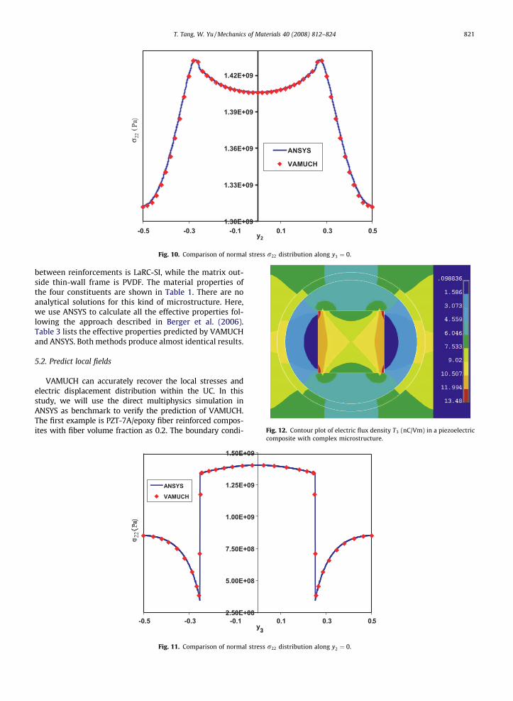
Fig. 10. Comparison of normal stress r22 distribution along y3 ¼ 0.
Fig. 12. Contour plot of electric flux density T3 (nC/Vm) in a piezoelectric
T. Tang, W. Yu / Mechanics of Materials 40 (2008) 812–824 821
between reinforcements is LaRC-SI, while the matrix out-side thin-wall frame is PVDF. The material properties ofthe four constituents are shown in Table 1. There are noanalytical solutions for this kind of microstructure. Here,we use ANSYS to calculate all the effective properties fol-lowing the approach described in Berger et al. (2006).Table 3 lists the effective properties predicted by VAMUCHand ANSYS. Both methods produce almost identical results.
5.2. Predict local fields
VAMUCH can accurately recover the local stresses andelectric displacement distribution within the UC. In thisstudy, we will use the direct multiphysics simulation inANSYS as benchmark to verify the prediction of VAMUCH.The first example is PZT-7A/epoxy fiber reinforced compos-ites with fiber volume fraction as 0.2. The boundary condi-
2.50E+08
5.00E+08
7.50E+08
1.00E+09
1.25E+09
1.50E+09
-0.5 -0.3 -0.1 0.1 0.3 0.5
ANSYS
VAMUCH
22
y23
Fig. 11. Comparison of normal stress r22 distribution along y2 ¼ 0.
composite with complex microstructure.

822 T. Tang, W. Yu / Mechanics of Materials 40 (2008) 812–824
tions applied to the UC are �22 ¼ 1:0% and E2 ¼ 100 V=m andall other mechanical strains and gradients of electric potentialare set to zero. Due to the difference of material properties oftwo constituents, the distribution of local stresses is not uni-form within the UC. Figs. 8 and 9 show the contour plots of thedistributions of r22 and r23. All sudden changes of local stres-ses at the interface between fibers and matrix are well cap-tured by VAMUCH. For quantitative comparison, we alsoplot r22 predicted by VAMUCH and the direct multiphysicssimulation of ANSYS along the lines y3 ¼ 0 and y2 ¼ 0 in Figs.10 and 11, respectively. It is obvious that the predictions ofVAMUCH have excellent agreement with those of ANSYS.
Fig. 13. Contour plot of electric flux density T2 (nC/Vm) in a
-1.5
2.5
6.5
10.5
-0.5 -0.3 -0.1
AV
y2
Elec
tric
dis
plac
emen
t T3
(nC
/Vm
)
Fig. 14. Electric flux density T3 distribution along y3 ¼ 0 in a
The second example is the composite with complexmicrostructure as shown in Fig. 7. The mechanical strainson all surfaces of UC are constrained. The contours of localelectric displacement distribution T3 and T2 resulting from100 V/m in the y3 direction predicted by VAMUCH isshown in Figs. 12 and 13. For a quantitative comparison,we also plot the local electric displacement distributionT3 along y3 ¼ 0 predicted by VAMUCH and ANSYS asshown in Fig. 14. It can be observed that there is excellentagreement between these two sets of results.
In the aforementioned two examples, the contour plotsof ANSYS are not shown because they are indistinguishable
piezoelectric composite with complex microstructure.
0.1 0.3 0.5
NSYSAMUCH
piezoelectric composite with complex microstructure.

T. Tang, W. Yu / Mechanics of Materials 40 (2008) 812–824 823
from those of VAMUCH. It is emphasized here that ANSYSresults are obtained through the direct multiphysics simu-lation of the unit cell using piezoelectric elements underspecified loading without using a micromechanics ap-proach to obtain the effective properties first, while VA-MUCH calculates the effective material properties firstand use these effective properties to carry out a macro-scopic analysis of the homogenized microstructure to ob-tain the global fields and then recover the local fieldswithin the original heterogeneous microstructure.
6. Conclusion
The variational asymptotic method for unit cell homog-enization (VAMUCH) has been applied to construct amicromechanics model for predicting the effective proper-ties and the local fields of piezoelectric composites. Incomparison to existing models, the present model hasthe following unique features:
(1) It adopts the variational asymptotic method as itsmathematical foundation. It invokes only essentialassumptions inherent in the concept of micro-mechanics.
(2) It has an inherent variational nature and its numer-ical implementation is shown to be straightforward.
(3) It handles 1D/2D/3D unit cells uniformly. Thedimensionality of the problem is determined bythe periodicity of the unit cell.
The present theory is implemented in the computerprogram, VAMUCH. Numerous examples have clearlydemonstrated its application and accuracy as a general-purpose micromechanical analysis tool. Although forthe examples we have studied, VAMUCH results are almostidentical to the results obtained by some FEM-basedmicromechanics analysis (Pettermann and Suresh,2000; Berger et al., 2006), VAMUCH has the followingadvantages:
(1) VAMUCH can obtain the complete set of materialproperties within one analysis, which is more effi-cient than those approaches requiring multiple runsunder different boundary and load conditions. Fur-thermore, it is not a trivial issue to apply the rightboundary conditions to obtain a correct FEM-basedmicromechanical analysis.
(2) VAMUCH calculates effective properties and localfields directly with the same accuracy as the fluctu-ation functions. No postprocessing calculationswhich introduces more approximations, such asaveraging stress and electric displacement field, areneeded, which are indispensable for FEM-basedmicromechanical analysis.
(3) VAMUCH can deal with general anisotropy for effec-tive materials which means VAMUCH can calculate21 constants for the effective elastic constants, 18constants for the effective piezoelectric constants,6 for the effective dielectric constants, while FEM-based micromechanical analyses have difficulties
to predict effective material having constants morethan orthotropic materials.
Acknowledgements
The present work is supported, in part, by the NationalScience Foundation under Grant DMI-0522908 and theState of Utah Community/University Research InitiativeGrant. The views and conclusions contained herein arethose of the authors and should not be interpreted as nec-essarily representing the official policies or endorsement,either expressed or implied, of the funding agencies. Theauthors want to sincerely thank Dr. Harald Berger fromOtto-von-Guericke-University of Magdeburg, Germany,for technical discussions and kindly providing the ANSYSmacro files and the data of effective properties of PZT-7Afiber reinforced composites.
References
Banno, H., 1983. Recent developments of piezoelectric ceramic productsand composites of synthetic rubber and piezoelectric ceramicparticles. Ferroelectrics 50, 329–338.
Benveniste, Y., 1987. A new approach to the application of Mori–Tanaka’stheory in composite materials. Mechanics of Materials 6, 147–157.
Benveniste, Y., 1992. The determination of the elastic and electric fields ina piezoelectric inhomogeneity. Journal of Applied Physics 72, 1086–1095.
Berdichevsky, V.L., 1977. On averaging of periodic systems. PMM 41 (6),993–1006.
Berger, H., Kari, S., Gabbert, U., Rodriguez-Ramos, R., Bravo-Castillero, J.,Guinovart-Diaz, R., Sabina, F., Maugin, G., 2006. Unit cell models ofpiezoelectric fiber composites for numerical and analyticalcalculation of effective properties. Smart Materials and Structures15, 451–458.
Bisegna, P., Luciano, R., 1996. Variational bounds for the overall propertiesof piezoelectric composites. Journal of the Mechanics and Physics ofSolids 44, 583–602.
Bisegna, P., Luciano, R., 1997. On methods for bounding the overallproperties of periodic piezoelectic fibrous composites. Journal of theMechanics and Physics of Solids 45, 1329–1356.
Budiansky, B., 1965. On the elastic moduli of some heterogeneousmaterials. Journal of the Mechanics and Physics of Solids 13, 223–227.
Chan, H., Unsworth, J., 1989. Simple model for piezoelectric ceramic/polymer 1–3 composites used in ultrasonic transducer applications.IEEE Transactions on Ultrasonics, Ferroelectrics, and FrequencyControl 36, 434–441.
Chen, T., 1993. Piezoelectric properties of multiphase fibrous composites:some theoretical results. Journal of the Mechanics and Physics ofSolids 41, 1781–1794.
Dunn, M., Taya, M., 1993a. An analysis of piezoelectric compositematerials containing ellipsoidal inhomogeneities. Proceedings of theRoyal Society of London, Series A 443, 265–287.
Dunn, M., Taya, M., 1993b. Micromechanics predictions of the effectiveelectroelastic moduli of piezoelectric composites. InternationalJournal of Solids and Structures 30, 161–175.
Dunn, M., Taya, M., 1994. Micromechanical estimates of the overallthermoelectroelastic moduli of multiphase fibrous composites.International Journal of Solids and Structures 31, 3099–3111.
Eshelby, J., 1957. The determination of the elastic field of an ellipsoidalinclusion, and related problems. Proceedings of the Royal Society ofLondon, Series A 241, 376–396.
Fakri, N., Azrar, L., El Bakkali, L., 2003. Electroelastic behavior modeling ofpiezoelectric composite materials containing spatiallly oritentedreinforcements. International Journal of Solids and Structures 40,361–384.
Gaudenzi, P., 1997. On the electromechanical response of activecomposite materials with piezoelectic inclusions. Computers andStructures 65, 157–168.
Hill, R., 1965. A self-consistent mechanics of composite materials. Journalof the Mechanics and Physics of Solids 13, 213–222.
824 T. Tang, W. Yu / Mechanics of Materials 40 (2008) 812–824
Huang, J., Kuo, W., 1996. Micromechanics determination of the effectiveproperties of piezoelectric composites containing spatially orientedshort fibers. Acta Materialia 44, 4889–4898.
Kunin, I., 1982. Theory of Elastic Media with Microstructure, vols. 1 and 2.Springer Verlag.
Lenglet, E., Hladky-Hennion, A., Debus, J., 2003. Numericalhomogenization techniques applied to piezoelectric composites.Journal of the Acoustical Society of America 113, 826–833.
Li, J., Dunn, M., 2001. Variational bounds for the effective moduliof heterogeneous piezoelectric solids. Philosophical Magazine 81,903–926.
Li, S., 2000. General unit cells for micromechanical analysis ofunidirectional composites. Composites A 32, 815–826.
McLaughlin, R., 1977. A study of the differential scheme for compositematerials. International Journal of Engineering Science 15, 237–244.
Mori, T., Tanaka, K., 1973. Average stress in matrix and average elasticenergy of materials with misfitting inclusions. Acta Metallurgica 21,571–574.
Newnham, R., Skinner, D., Cross, L., 1978. Connectivity and piezoelectri-pyroelectric composites. Materials Research Bulletin 13, 525–536.
Norris, A., 1985. A differential scheme for the effective moduli ofcomposites. Mechanics of Materials 4, 1–16.
Odegard, G.M., 2004. Constitutive modeling of piezoelectric polymercomposites. Acta Materialia 52 (18), 5315–5330.
Pastor, J., 1997. Homogenization of linear piezoelectric media. MechanicsResearch Communications 24, 145–150.
Pettermann, H., Suresh, S., 2000. A comprehensive unit cell model: Astudy of coupled effects in piezoelectric 1–3 composites. InternationalJournal of Solids and Structures 37, 5447–5464.
Poizat, C., Sester, M., 1999. Effective properties of composites withembedded piezoelectric fibers. Computational Materials Science 16,89–97.
Smith, W., Auld, B., 1991. Modeling 1–3 composites piezoelectrics:thickness-mode oscillations. IEEE Transactions on Ultrasonics,Ferroelectrics, and Frequency Control 38, 40–47.
Sun, H., Di, S., Zhang, N., Wu, C., 2001. Micromechanics of compositematerials using multivariable finite element method andhomogenization theory. International Journal of Solids andStructures 38, 3007–3020.
Tang, T., Yu, W., 2007a. A variational asymptotic micromechanicsmodel for predicting conductivity of composite materials.Journal of Mechanics of Materials and Structures 2, 1813–1830.
Tang, T., Yu, W., Nov. 10–16 2007b. A variational asymptotic model forpredicting initial yielding surface and elastoplastic behavior of metalmatrix composite materials. In: Proceedings of the 2007 ASMEInternational Mechanical Engineering Congress and Exposition.ASME, Seattle, Washington.
Wang, B., 1992. Three dimensional analysis of an ellipsoidal inclusion in apiezoelectic material. International Journal of Solids and Structures29, 293–308.
Yu, W., Tang, T., 2007a. Variational asymptotic method for unit cellhomogenization of periodically heterogeneous materials.International Journal of Solids and Structures 44, 3738–3755.
Yu, W., Tang, T., 2007b. A variational asymptotic micromechanicsmodel for predicting thermoelastic properties of heterogeneousmaterials. International Journal of Solids and Structures 44,7510–7525.