Embed Size (px)
Citation preview

2. Introduction
Mechanics of Materials
Dr. Rami Zakaria
References:
1. Engineering Mechanics: Statics, R.C. Hibbeler, 12th ed, Pearson
2. Mechanics of Materials: R.C. Hibbeler, 9th ed, Pearson
3. Mechanics of Materials: J.M. Gere & B.J. Goodno, 8th ed, Cengage Learning

Terminology
2
Term Definition Notes
Stress the intensity of the internal force acting on an area
Deformation Changing of the shape of a subject
Load/Loading Forces/force curve
Resultant Force Overall force
Strain The intensity of deformation at a point in an object
Member A structure unit (such as a bar, a beam, etc.)
Compression Applying two forces towards each others
Tension Applying two forces away from each others
Translation Moving along a straight line
Rotation Moving in a circular way

3
Mechanics of materials is a branch of applied mechanics that studies the
behavior of solid bodies (such as bars and beams) subjected to external loading.
This involves finding the internal effects (stress and strain ) in a solid body,
which is important for the safe design of structures (in bridges, buildings,
airplanes, etc…).
Stress is associated with the strength of the material from which the body is made,
while strain is a measure of the deformation of the body.
What is Mechanics of Materials?

This steel framework is subjected to stress.
How does this affect the design of the framework and its connections?
• We will review some of the important principles of
statics and how to determine the internal resultant
loadings in a body.
• Afterwards we will learn the concepts of normal
stress (σ) and shear stress (τ) and study members
subjected to an axial load or direct shear.
4

A SHORT REVIEW OF
STATICS
5

External Loads
Reactive forces
Body forces: They are developed when one body exerts a
force on another, without direct physical
contact between them.
For examples: the effects caused by the
earth’s gravitation (weight!), or its
electromagnetic field. Although body forces
affect all the particles of the body, we usually
represent them by a single concentrated force
(for example centre of Gravity).
Surface forces: caused by the direct contact of one
body with another. They are
distributed over the area of contact
between the bodies.
-If it is applied on a small area (in
comparison with the total surface
area of the body), then the
surface force can be idealized as
a single concentrated force (at
one point on the body).
-If it is applied along a narrow
strip of area, the loading can be
idealized as a distributed line of
forces.
Active Forces
Support reactions 6

Why do we need “statics” here?!
Because in Mechanics of Materials we need to know all forces acting on the body.
When in equilibrium, the net force and net moment acting on a body are zero.
Equations of equilibrium :
0
0
M
F
0,0,0
0,0,0
zyx
zyx
MMM
FFF
0
,0,0
o
yx
M
FF
Equilibrium of a Rigid Body
7
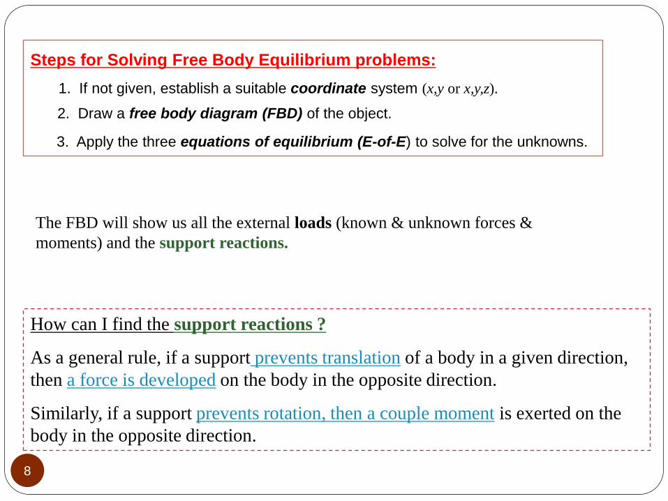
Steps for Solving Free Body Equilibrium problems:
1. If not given, establish a suitable coordinate system (x,y or x,y,z).
2. Draw a free body diagram (FBD) of the object.
3. Apply the three equations of equilibrium (E-of-E) to solve for the unknowns.
The FBD will show us all the external loads (known & unknown forces &
moments) and the support reactions.
How can I find the support reactions ?
As a general rule, if a support prevents translation of a body in a given direction,
then a force is developed on the body in the opposite direction.
Similarly, if a support prevents rotation, then a couple moment is exerted on the
body in the opposite direction.
8

Prevents translation in one
direction
Prevents translation in
all directions
Prevents translation in one
direction, and prevents rotation
Pre
ven
ts tra
nsl
atio
n in
all
dir
ecti
ons,
an
d
pre
ven
ts r
ota
tio
n
Support Reaction

• q is a line load (N/m or lb/ft)
The resultant force FR of q , acts through the
centroid C (or centre of area) and it is
equivalent to the area under the distributed
loading curve.
Overall FBD Separate Parts FBD
Distributed Loads
Ref [3]

Notice the internal forces and moments:
11 Ref [3]

•p is a surface pressure (N/m2 or lb/ft2)
• w is a body force (N/m3 or lb/m3)
In case of 3D systems
Remember:
When we have a simple structure, members can be
subjected to either compression or tension forces.
We can calculate these forces using the concepts of
statics.
When we know the forces at the ends of each of the members, we can determine the
internal forces in these members, by looking at a cross-section at an arbitrary point.
12

In such cases, w(x) is the load intensity
distribution function and it has units of
force per length.
We will analyze the most common case of
a distributed pressure loading. This is a
uniform load along one axis of a flat
rectangular body.
dxxwdF )(
The net force on the beam is given by
+
Here A is the area under the loading curve w(x).
LL
R AdxxwdFF )(
Distributed Loading Review
13 Ref [1]

Location of the Resultant Force
The total moment about point O is given as
Assuming that FR acts at , it will produce the
moment about point O as
The force dF will produce a moment of (x)(dF)
about point O.
x
LL
Ro dxxxwxdFM )(
L
RRo dxxwxFxM )()()(
14 Ref [1]
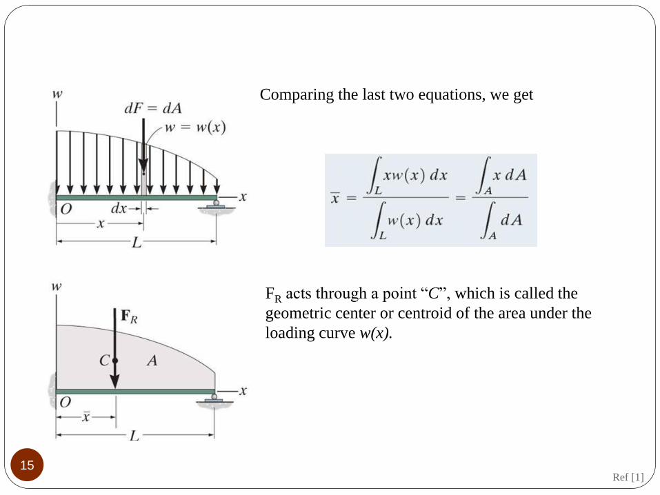
Comparing the last two equations, we get
FR acts through a point “C”, which is called the
geometric center or centroid of the area under the
loading curve w(x).
15 Ref [1]

Example: Determine the magnitude
and location of the equivalent resultent
force (FR) acting on the shaft
Ref [1]

Note: for simples shapes we can find the shift easily using the geometric centroid
Area Cx Cy
b.h b/2 h/2
b.h/2 (a +b)/3 h/3
π.a2 a a
π.a2 /2 a 4.a /3.π
17

The rectangular load:
ftx
lbFR
52
10
400010400
The triangular loading:
mx
NFR
43
66
180066002
1
18
Examples:

Example about support reaction calculations
Given: The 4kN load at B of the beam
is supported by pins at A and C .
Find: The support reactions at A and C.
FBD of the beam:
AX
AY
A
1.5 m
C B
4 kN
FC
45°
1.5 m Solution:
+ FX = AX + 11.31 cos 45 = 0; AX = – 8.00 kN
+ FY = AY + 11.31 sin 45 – 4 = 0; AY = – 4.00 kN
MA = (FC sin 45) (1.5) – (4) (3) = 0
Fc = 11.31 kN
Ref [1]

Simple Truss
20 Ref [1]

The solution has finished until here! But let’s see the
reaction components at joint (A)
All reaction forces together 21 Ref [1]

22
Statics is used to determine the resultant loadings that act within a body.
Consider a body in equilibrium by four external forces (neglect the weight for now). In
order to obtain the internal loadings acting on a specific region, let’s pass an imaginary
section (cut) through the region of interest. Separate the two parts and draw the free-
body diagram of one of them.
There is a distribution of internal forces acting on the area of the cross section.
We can represent these forces by a resultant force FR and moment MRo, at any point
O (usually the centroid). Here, we are interested in the normal and perpendicular
components of FR and MRo.
Internal Resultant Loadings

Therefore, we can define 4 types of loading:
Normal force, N: This force acts perpendicular to the area. It
is developed when the external loads tend to push or pull on
the two segments of the body.
Shear force, V: The shear force lies in the plane of the area. It
is developed when the external loads tend to cause the two
segments to slide over one another.
Bending moment, M: It is developed when the external loads tend to bend the body
about an axis lying on the area.
Torsional moment (torque) , T: It is developed when the external loads tend to twist
one segment of the body about an axis perpendicular to the area.
This exists only in a 3D system
23 Ref [2]

• Mechanics of materials is a study of the relationship between the
external loads applied to a body and the stress and strain caused by
the internal loads within the body.
• A support produces a force in a particular direction on its attached
member if it prevents translation of the member in that direction,
and it produces a couple moment on the member if it prevents
rotation.
• In general the internal resultant loadings acting on a body are :a
normal force, shear force, torsional moment, and bending moment.
We can determine them by making a cross-section through the body.
24
Important Points:

(Calculating The resultant internal loadings at a point located on the section of a body )
1. Determine the Support Reactions.
2. Draw the Free-Body Diagram.
( indicate the unknown resultants N, V, M, and T )
3. Write and solve the Equations of Equilibrium.
Note: If the solution is negative, the assumed directional sense of the resultant is opposite to
that shown on the free-body diagram
only in a 3D system
25
Procedure for Analysis:
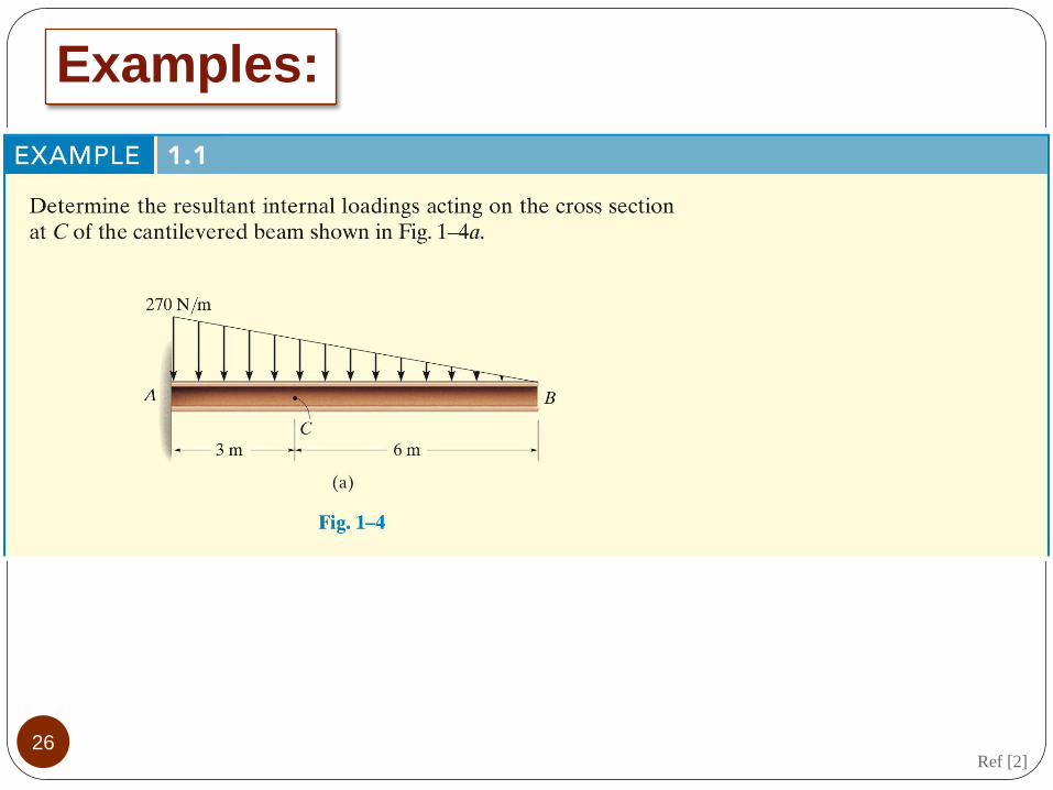
26
Examples:
Ref [2]

27 Ref [2]

EXAMPLE 1.2
Ref [2] 28

29 Ref [2]

30 Ref [2]

EXAMPLE 1.3 (CONTINUED) lbFFF
lbFFF
BDBDy
BABAx
465005
377500
775005
462000
Ref [2] 31
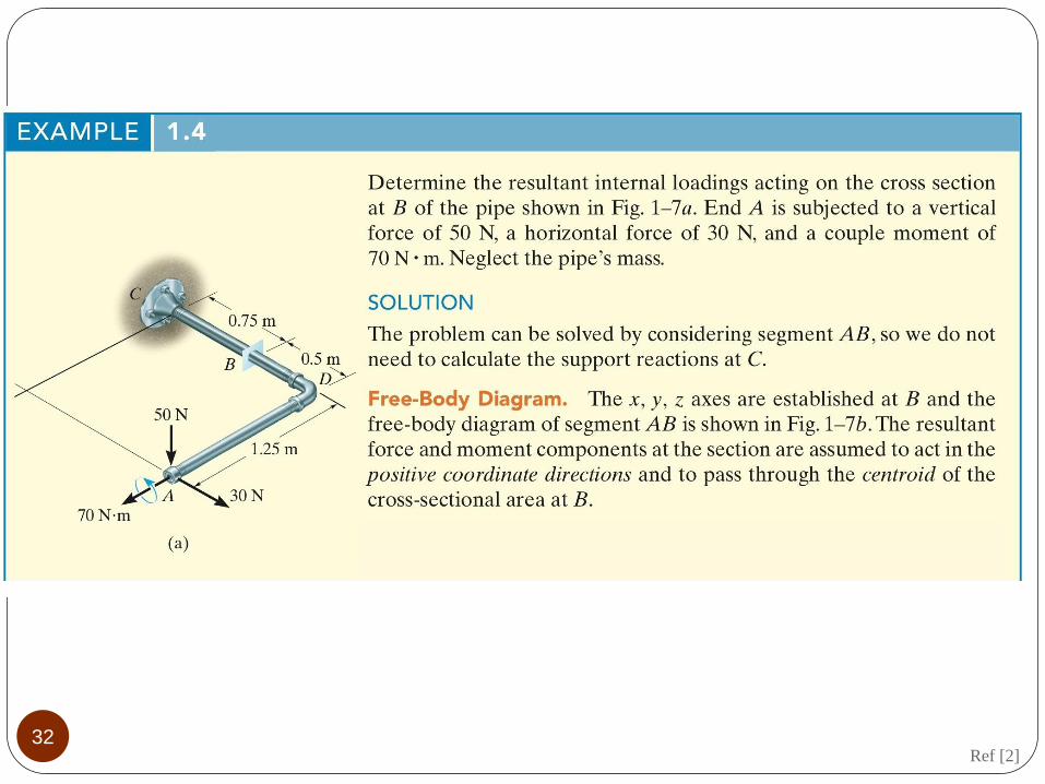
32 Ref [2]

33 Ref [2]

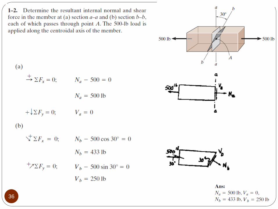
Problems:
34
Student’s solution:

35
36

37
Student’s solution:

38

39
Student’s solution:

40


42

Student’s solution:


![Mechanics] MIT Materials Science and Engineering - Mechanics of Materials (Fall 1999)](https://img.pdfslide.us/doc/110x75/552532ce5503462a6f8b4744/mechanics-mit-materials-science-and-engineering-mechanics-of-materials-fall-1999.jpg)