Embed Size (px)
Citation preview
Mechanics of Materials IIMechanics of Materials II
UET, TaxilaUET, Taxila
Lecture No. (2)Lecture No. (2)
Tensile behavior of Tensile behavior of different materials:different materials:
In a typical tensile test one tries In a typical tensile test one tries to induce uniform extension of to induce uniform extension of the gage section of a tensile the gage section of a tensile specimen. specimen.
The gage section of the The gage section of the tensile specimen is tensile specimen is normally of uniform normally of uniform rectangular or circular rectangular or circular cross-section. cross-section.
The following figure shows a The following figure shows a typical dog-bone sample. typical dog-bone sample.
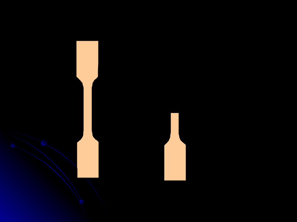
Gage length
P
P
P
P
The two ends are used for fixing The two ends are used for fixing into the grips, which apply the into the grips, which apply the load. As can be seen from the load. As can be seen from the free-body diagram to the right, free-body diagram to the right, the load in the gage section is the load in the gage section is the same as the load applied by the same as the load applied by the grips. the grips.
An extensometers are used An extensometers are used to measure the change of to measure the change of length in the gage section length in the gage section and load cells to measure and load cells to measure the load applied by the grips the load applied by the grips on the sample. on the sample.
By the means of this it is By the means of this it is possible to calculate the axial possible to calculate the axial strain and normal stress strain and normal stress (knowing the initial gage (knowing the initial gage length and cross-sectional length and cross-sectional area of the gage section). area of the gage section).
The result is a stress-strain The result is a stress-strain diagram, a diagram of how diagram, a diagram of how stress is changing in the stress is changing in the sample as a function of the sample as a function of the strain for the given loading. A strain for the given loading. A typical stress-strain diagram typical stress-strain diagram for a mild steel is shown for a mild steel is shown below.below.
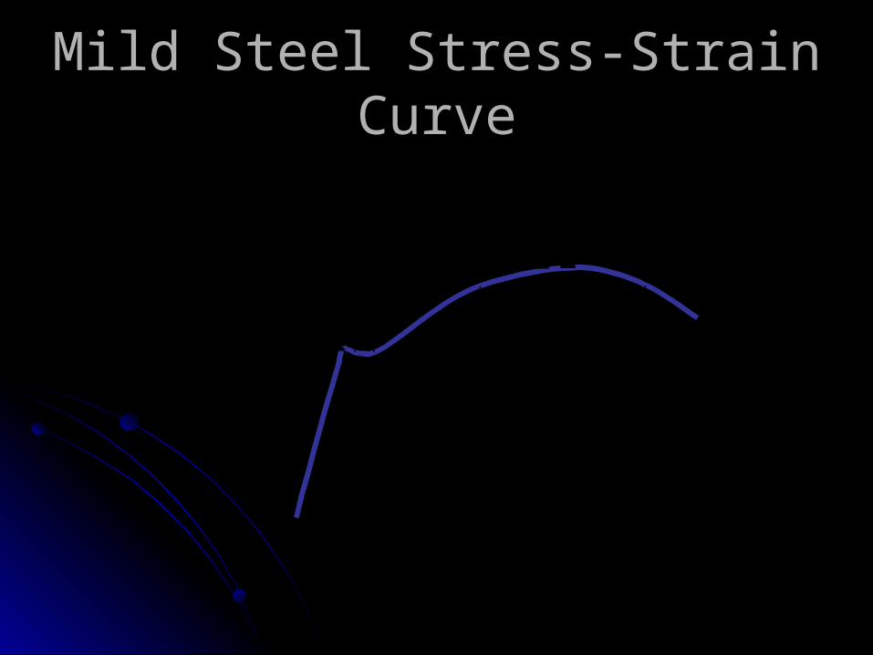
Mild Steel Stress-Strain CurveMild Steel Stress-Strain Curve
Yield stress, y
Ultimate stress, u
Stress,
Strain,
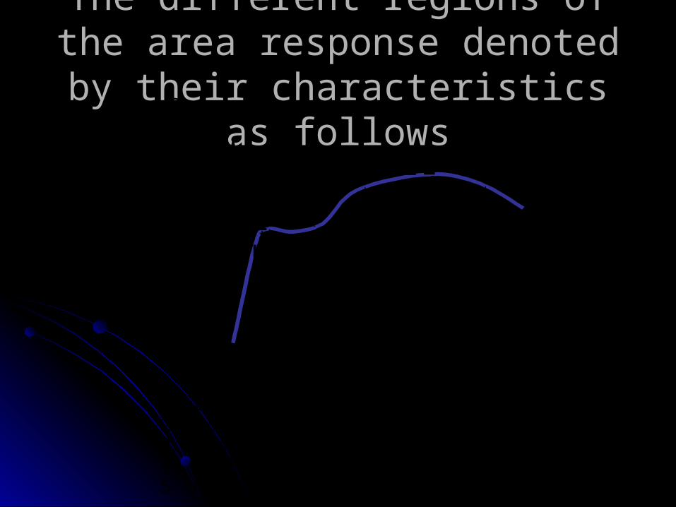
The different regions of the area The different regions of the area response denoted by their response denoted by their characteristics as followscharacteristics as follows
Yield stress, y
Ultimate stress, u
Stress,
Strain,
1 2
3 4 5
1. Linear elastic: region of proportional elastic loading 2. Nonlinear elastic: up to yield 3. Perfect plasticity: plastic flow at constant load 4. Strain hardening: plastic flow with the increase of stress 5. Necking: localization of deformation and rupture
Brittle versus Ductile Brittle versus Ductile behaviorbehaviorBrittle materialsBrittle materials fail at fail at
small strains and in small strains and in tension. Examples of tension. Examples of such materials are glass, such materials are glass, cast iron, and ceramics. cast iron, and ceramics.
Ductile materialsDuctile materials fail at fail at large strains and in large strains and in shear. Examples of shear. Examples of ductile materials are mild ductile materials are mild steel, aluminum and steel, aluminum and rubber. rubber.

The The ductilityductility of a material of a material is is characterized by the characterized by the strain at which the strain at which the material failsmaterial fails. .
An An alternate measurealternate measure is is the percent reduction in the percent reduction in cross-sectional areacross-sectional area at at failure.failure.
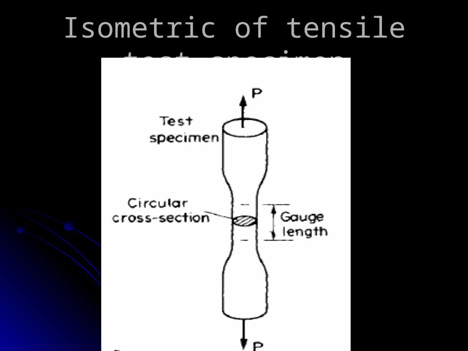
Isometric of tensile test Isometric of tensile test specimenspecimen
Different types of Different types of response:response:Elastic response:Elastic response:
If the loading and unloading If the loading and unloading stress-strain plot overlap each stress-strain plot overlap each other the response is elastic. other the response is elastic. The response of steel below The response of steel below the yield stress is considered to the yield stress is considered to be elastic.be elastic.
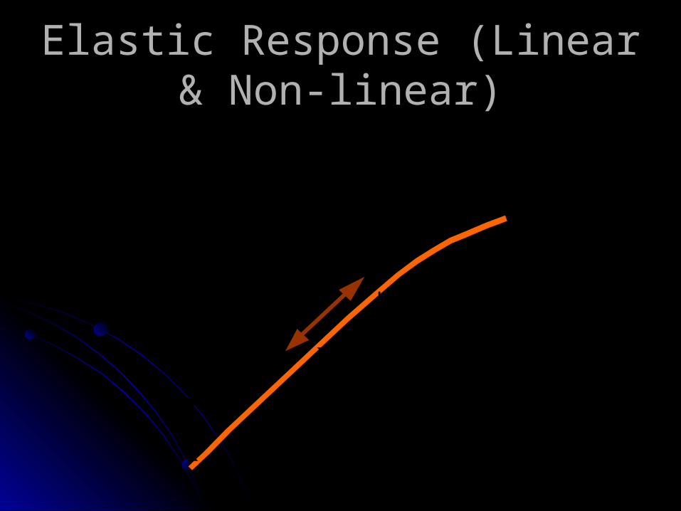
Elastic Response (Linear & Elastic Response (Linear & Non-linear)Non-linear)
Linear Elastic
Nonlinear Elastic

After loading beyond the After loading beyond the yield point, the material no yield point, the material no longer unloads along the longer unloads along the loading path. loading path.
There is a permanent There is a permanent stretch in the sample after stretch in the sample after unloading. unloading.
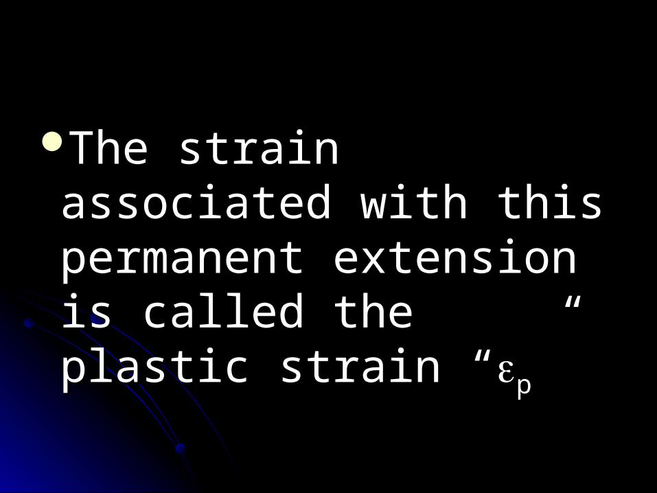
The strain associated The strain associated with this permanent with this permanent extension is called the extension is called the plastic strain “plastic strain “pp””
As shown in next figure, As shown in next figure, the unloading path is the unloading path is parallel to the initial parallel to the initial linear elastic loading linear elastic loading path (and not path (and not overlapping). overlapping).
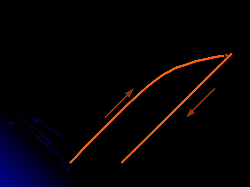
Unloading
Loading
p
Most plastics when loaded Most plastics when loaded deform over time even without deform over time even without increasing the load. The increasing the load. The material material continuous extension continuous extension under constantunder constant load referred to load referred to as as creepcreep. If held at constant . If held at constant strain, the load required to hold strain, the load required to hold the strain decreases with time. the strain decreases with time.
RelaxationRelaxationThe The decrease in load decrease in load over time at constant over time at constant stretchstretch is referred to as is referred to as relaxation.relaxation.
Bearing Stress:Bearing Stress:Even though bearing stress Even though bearing stress
is not a fundamental type of is not a fundamental type of stress, it is a useful concept stress, it is a useful concept for the design of for the design of connections in which one connections in which one part pushes against another. part pushes against another.
The compressive load The compressive load divided by a divided by a characteristic area characteristic area perpendicular to it yields perpendicular to it yields the bearing stress which the bearing stress which is denoted by “is denoted by “σσbb“. “.
Therefore, in form, the bearing Therefore, in form, the bearing stress is no different from the stress is no different from the
compressive axial stress and is compressive axial stress and is given by:given by:
A
Fb
Where:Where:
F: F: is the compressive load is the compressive load andand
A: A: is a characteristic area is a characteristic area perpendicular to it.perpendicular to it.
F
p
F
F
F
F F
F
F
d
t
t
t t
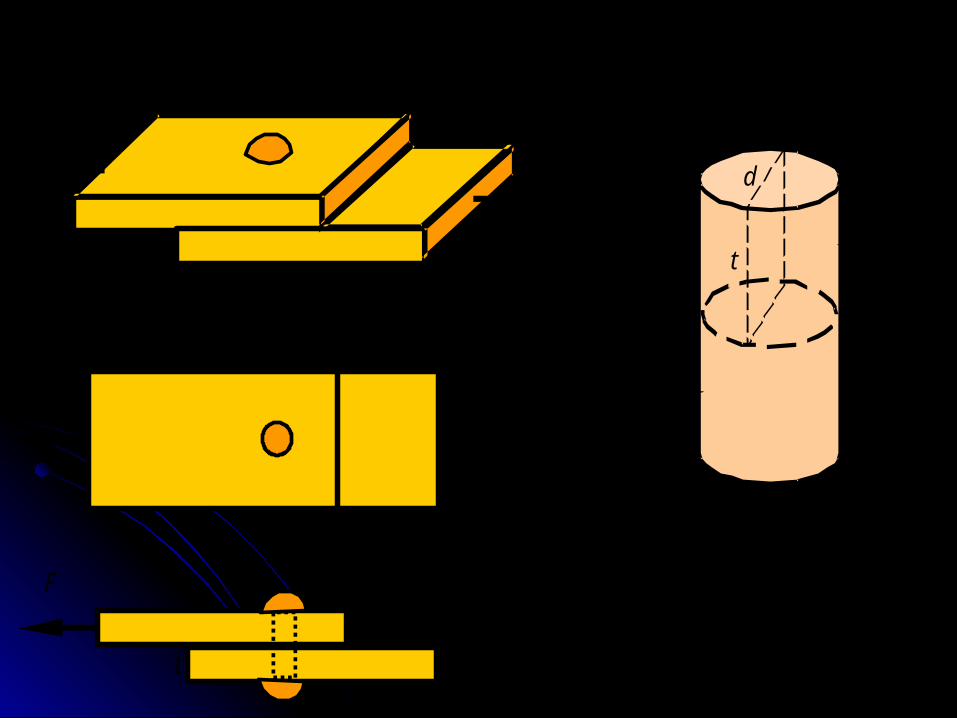
Cylindrical bolt or rivet
For example, if two For example, if two plates are connected by plates are connected by a bolt or rivet as shown, a bolt or rivet as shown, each plate pushes each plate pushes against the side of the against the side of the bolt with load bolt with load FF. .
It is not clear what the It is not clear what the contact area between the contact area between the bolt and the plate is since it bolt and the plate is since it depends on the size of the depends on the size of the bolt and the shape of the bolt and the shape of the deformation that results. deformation that results.
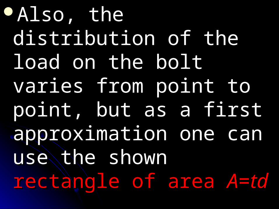
Also, the distribution of the Also, the distribution of the load on the bolt varies from load on the bolt varies from point to point, but as a first point to point, but as a first approximation one can use approximation one can use the shown the shown rectangle of rectangle of area area AA==tdtd

This gives a representative This gives a representative bearing stress for the bolt as:bearing stress for the bolt as:
td
Fb
Linear-Elastic Linear-Elastic Response and Response and
Factor of SafetyFactor of SafetyLinear-elastic response:Linear-elastic response:
Hooke’s law:Hooke’s law:
In the linear elastic portion of the In the linear elastic portion of the response of material one can response of material one can model the response by Hooke’s model the response by Hooke’s law as followslaw as follows
Hooke’s law for extension:Hooke’s law for extension:
σσ = E = E
Hooke’s law for shear: Hooke’s law for shear:
= G = G
Where:Where:EE is the elastic modulus (or is the elastic modulus (or Young’s modulus),Young’s modulus), and and
GG is the shear modulus. is the shear modulus. The The elastic and shear moduli elastic and shear moduli
are material constantsare material constants characterizing characterizing
the stiffness of the material. the stiffness of the material.
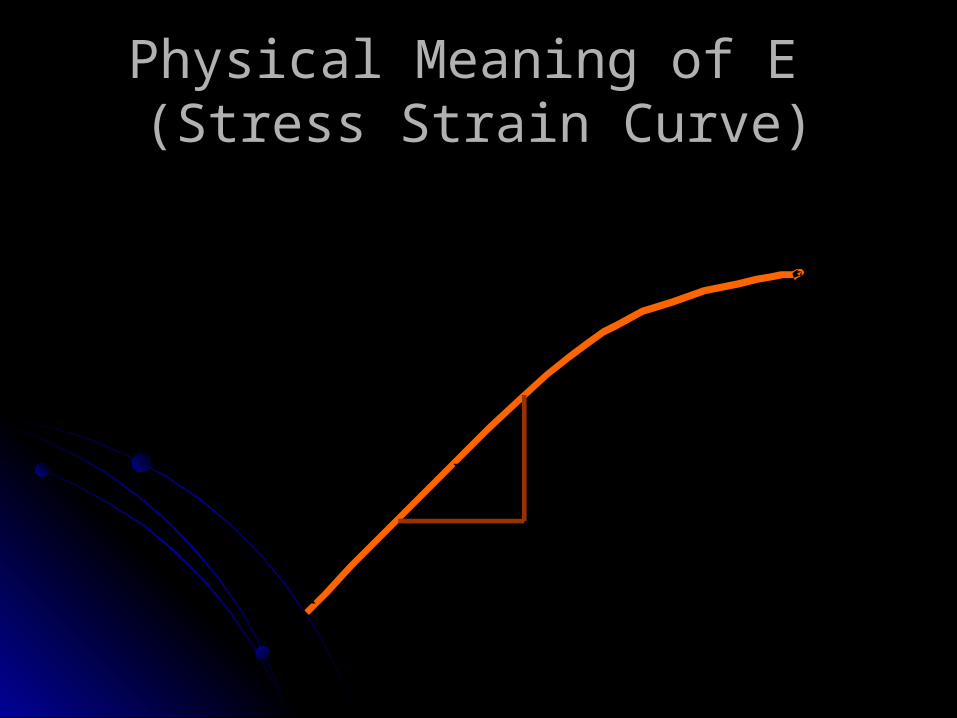
Physical Meaning of E Physical Meaning of E (Stress Strain Curve)(Stress Strain Curve)
E
1
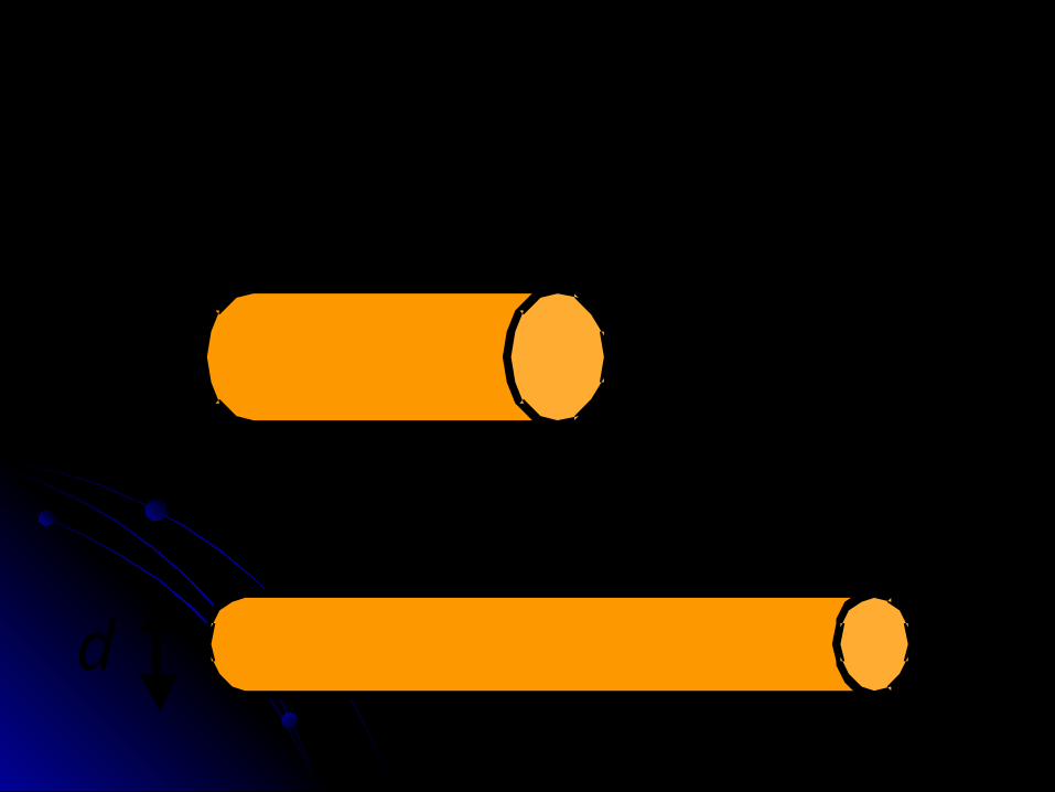
Poisson’s Ratio:Poisson’s Ratio:
Another material Another material parameter is Poisson’s parameter is Poisson’s ratio that characterizes the ratio that characterizes the contraction in the lateral contraction in the lateral directions when a material directions when a material is extended. is extended.
The symbol The symbol (nu) is used for (nu) is used for the poison ration, which is the poison ration, which is negative the ratio of the lateral negative the ratio of the lateral strain to axial strain.strain to axial strain.
a
t
lo
do
l
d

o
ot d
dd

o
oa l
ll
The relation between the The relation between the elastic moduli:elastic moduli:
For an For an isotropic elastic materialisotropic elastic material (i.e., an elastic material for which (i.e., an elastic material for which the properties are the same the properties are the same along all directions)along all directions) there are there are only two independent material only two independent material constants. constants.
The relation between The relation between the three moduli are the three moduli are given by the following given by the following equation:equation:
Equation for the relation between the Equation for the relation between the elastic moduli:elastic moduli:
)1(2
EG
Factor of safety:Factor of safety:
The factor of safety The factor of safety denoted by denoted by ““n”n” is the ratio is the ratio of the load, the structure of the load, the structure can carry,can carry, divided by the divided by the load it is required to take. load it is required to take.
Factor of safetyFactor of safety
strengthRequired
strengthActualn
Therefore, Therefore, the factor of safety the factor of safety is a number greater than unity is a number greater than unity ((nn>1).>1). The allowable stress for The allowable stress for a given material is the a given material is the maximum stress the material maximum stress the material can takecan take (normally the ultimate (normally the ultimate or yield stress) divided by the or yield stress) divided by the factor of safety). factor of safety).

n
orn
or
uyallow
uyallow