Embed Size (px)
Citation preview
– Mechanics and Cooling –
for the LHCb UT Group
• Introduction
• Stave design and construction
Simulation & prototypes
Stave components
Stave construction
• Modules
• Superstructure
Frame and Box
• Summary and plans
6/16/2015R. Mountain, Syracuse University FORUM on Tracking Detector Mechanics 2

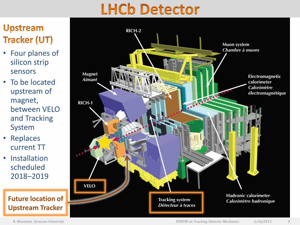
• Four planes of silicon strip sensors
• To be located upstream of magnet, between VELO and Tracking System
• Replaces current TT
• Installation scheduled 2018–2019
6/16/2015R. Mountain, Syracuse University FORUM on Tracking Detector Mechanics 4
Future location of Upstream Tracker
ELECTRONICS
ELECTRONICS VOLUME
VOLUME
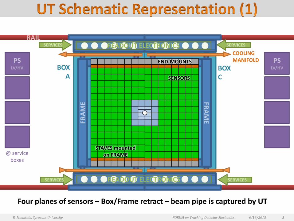
Four planes of sensors – Box/Frame retract – beam pipe is captured by UT
6/16/2015R. Mountain, Syracuse University FORUM on Tracking Detector Mechanics 5
RAIL
FRA
ME FR
AM
E
PSLV/HV
PSLV/HV
COOLING MANIFOLD
BOXA
@ service boxes
BOXC
SERVICES SERVICES
SERVICES SERVICES
END-MOUNTS
SENSORS
STAVES mountedon FRAME
READOUT ELECTRONICS
READOUT ELECTRONICS
6/16/2015R. Mountain, Syracuse University FORUM on Tracking Detector Mechanics 6
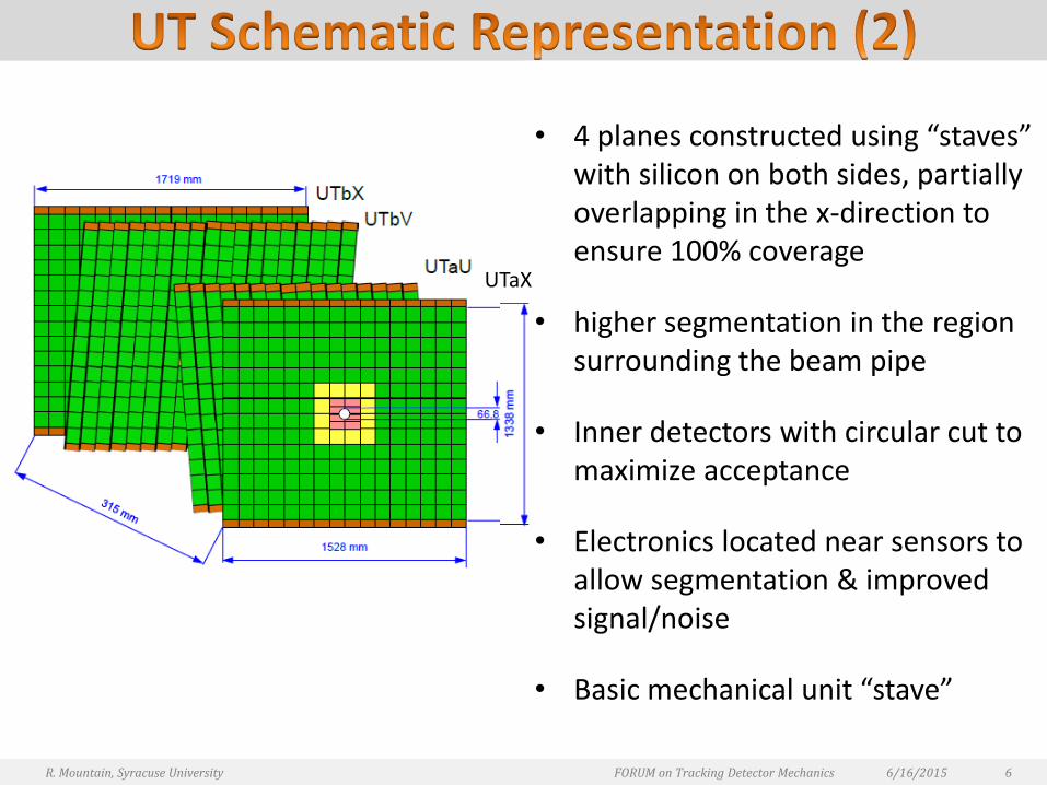
• 4 planes constructed using “staves” with silicon on both sides, partially overlapping in the x-direction to ensure 100% coverage
• higher segmentation in the region surrounding the beam pipe
• Inner detectors with circular cut to maximize acceptance
• Electronics located near sensors to allow segmentation & improved signal/noise
• Basic mechanical unit “stave”
UTaX

6/16/2015R. Mountain, Syracuse University FORUM on Tracking Detector Mechanics 7
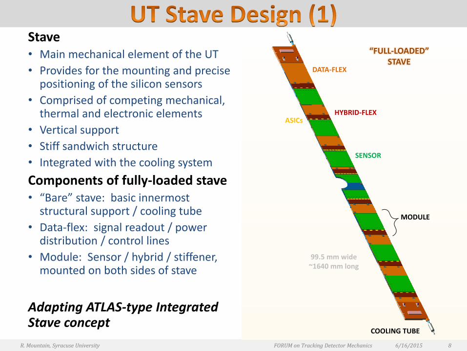
Stave • Main mechanical element of the UT
• Provides for the mounting and precise positioning of the silicon sensors
• Comprised of competing mechanical, thermal and electronic elements
• Vertical support
• Stiff sandwich structure
• Integrated with the cooling system
Components of fully-loaded stave• “Bare” stave: basic innermost
structural support / cooling tube
• Data-flex: signal readout / power distribution / control lines
• Module: Sensor / hybrid / stiffener, mounted on both sides of stave
Adapting ATLAS-type Integrated Stave concept
6/16/2015 8R. Mountain, Syracuse University FORUM on Tracking Detector Mechanics
“FULL-LOADED” STAVE
SENSOR
ASICs
COOLING TUBE
99.5 mm wide~1640 mm long
HYBRID-FLEX
DATA-FLEX
MODULE
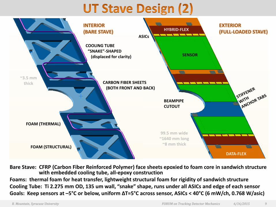
Bare Stave: CFRP (Carbon Fiber Reinforced Polymer) face sheets epoxied to foam core in sandwich structure with embedded cooling tube, all-epoxy construction
Foams: thermal foam for heat transfer, lightweight structural foam for rigidity of sandwich structureCooling Tube: Ti 2.275 mm OD, 135 um wall, “snake” shape, runs under all ASICs and edge of each sensorGoals: Keep sensors at –5°C or below, uniform ΔT=5°C across sensor, ASICs < 40°C (6 mW/ch, 0.768 W/asic)
SENSOR
~3.5 mmthick
ASICs
EXTERIOR (FULL-LOADED STAVE)
INTERIOR(BARE STAVE)
COOLING TUBE“SNAKE”-SHAPED
(displaced for clarity)
FOAM (STRUCTURAL)
FOAM (THERMAL)
99.5 mm wide~1640 mm long
~8 mm thick
BEAMPIPECUTOUT
CARBON FIBER SHEETS(BOTH FRONT AND BACK)
HYBRID-FLEX
DATA-FLEX
6/16/2015 9R. Mountain, Syracuse University FORUM on Tracking Detector Mechanics

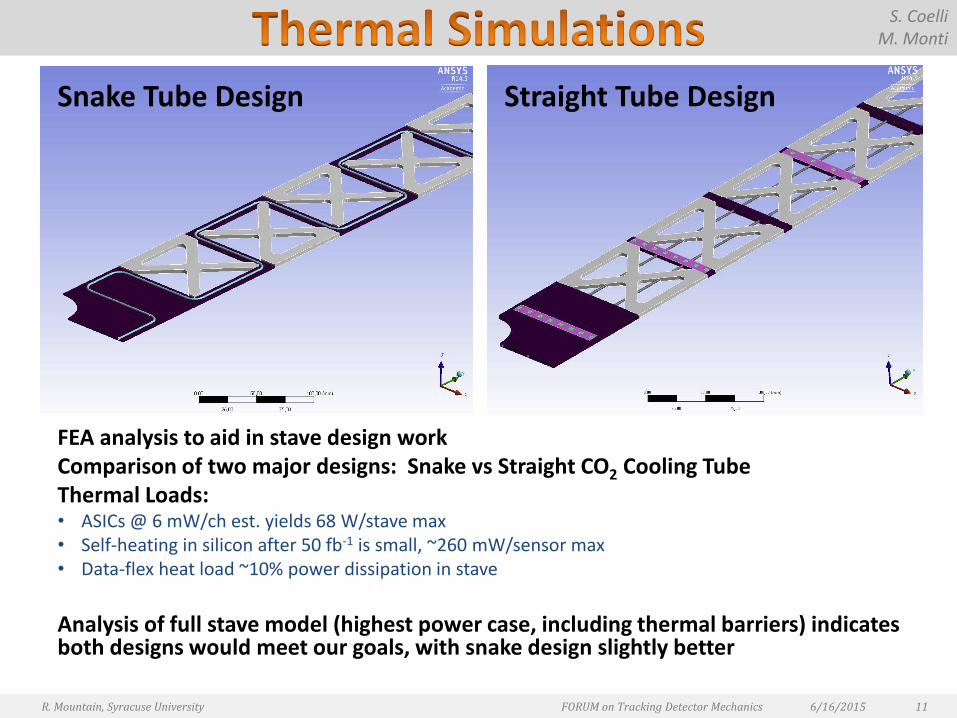
FEA analysis to aid in stave design workComparison of two major designs: Snake vs Straight CO2 Cooling Tube Thermal Loads: • ASICs @ 6 mW/ch est. yields 68 W/stave max• Self-heating in silicon after 50 fb-1 is small, ~260 mW/sensor max• Data-flex heat load ~10% power dissipation in stave
Analysis of full stave model (highest power case, including thermal barriers) indicates both designs would meet our goals, with snake design slightly better
6/16/2015R. Mountain, Syracuse University FORUM on Tracking Detector Mechanics 11
S. CoelliM. Monti
Straight Tube DesignSnake Tube Design
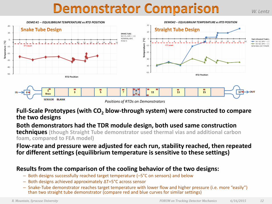
Full-Scale Prototypes (with CO2 blow-through system) were constructed to compare the two designsBoth demonstrators had the TDR module design, both used same construction techniques (though Straight Tube demonstrator used thermal vias and additional carbon foam, compared to FEA model)
Flow-rate and pressure were adjusted for each run, stability reached, then repeated for different settings (equilibrium temperature is sensitive to these settings)
Results from the comparison of the cooling behavior of the two designs:– Both designs successfully reached target temperature (–5°C on sensors) and below– Both designs achieved approximately ΔT=5°C across sensor– Snake-Tube demonstrator reaches target temperature with lower flow and higher pressure (i.e. more “easily”)
than two straight tube demonstrator (compare red and blue curves for similar settings)
6/16/2015R. Mountain, Syracuse University FORUM on Tracking Detector Mechanics 12
Positions of RTDs on Demonstrators
W. Lentz

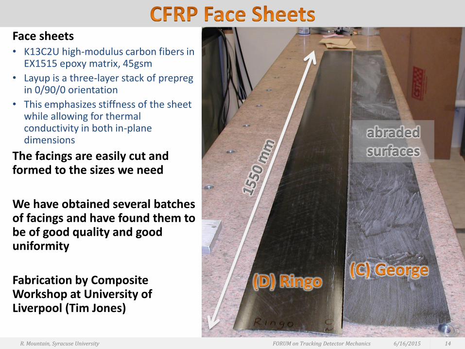
Face sheets • K13C2U high-modulus carbon fibers in
EX1515 epoxy matrix, 45gsm
• Layup is a three-layer stack of prepregin 0/90/0 orientation
• This emphasizes stiffness of the sheet while allowing for thermal conductivity in both in-plane dimensions
The facings are easily cut and formed to the sizes we need
We have obtained several batches of facings and have found them to be of good quality and good uniformity
Fabrication by Composite Workshop at University of Liverpool (Tim Jones)
6/16/2015R. Mountain, Syracuse University FORUM on Tracking Detector Mechanics 14
abraded surfaces
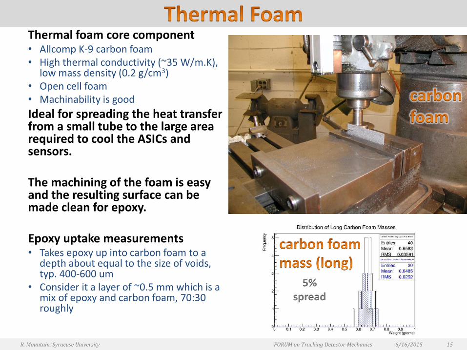
Thermal foam core component • Allcomp K-9 carbon foam• High thermal conductivity (~35 W/m.K),
low mass density (0.2 g/cm3)• Open cell foam• Machinability is good
Ideal for spreading the heat transfer from a small tube to the large area required to cool the ASICs and sensors.
The machining of the foam is easy and the resulting surface can be made clean for epoxy.
Epoxy uptake measurements• Takes epoxy up into carbon foam to a
depth about equal to the size of voids, typ. 400-600 um
• Consider it a layer of ~0.5 mm which is a mix of epoxy and carbon foam, 70:30 roughly
6/16/2015R. Mountain, Syracuse University FORUM on Tracking Detector Mechanics 15
5% spread
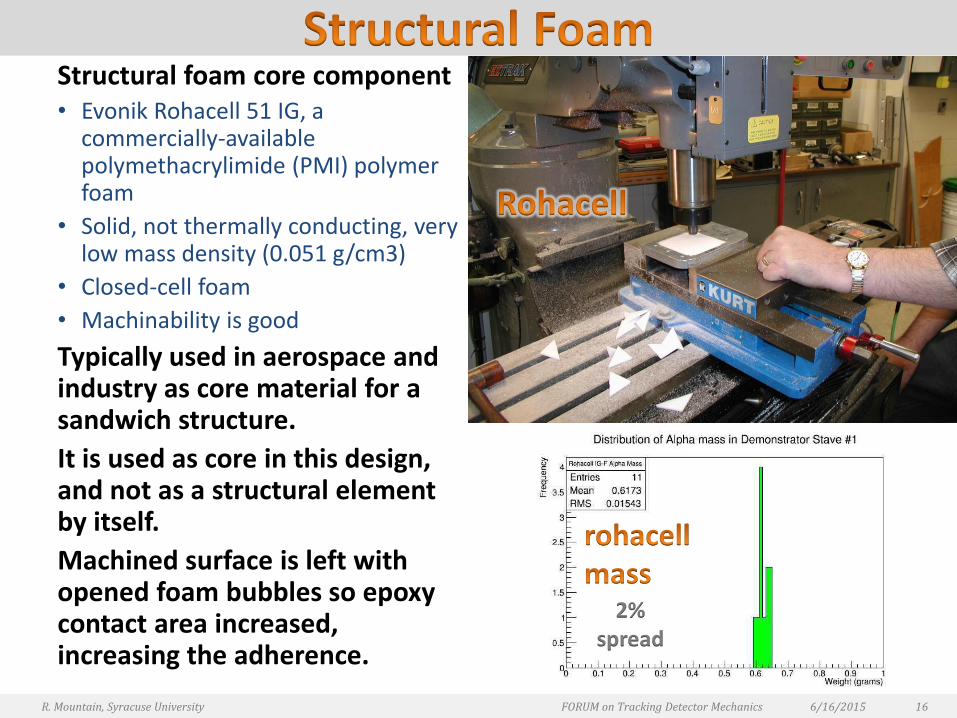
Structural foam core component• Evonik Rohacell 51 IG, a
commercially-available polymethacrylimide (PMI) polymer foam
• Solid, not thermally conducting, very low mass density (0.051 g/cm3)
• Closed-cell foam
• Machinability is good
Typically used in aerospace and industry as core material for a sandwich structure.
It is used as core in this design, and not as a structural element by itself.
Machined surface is left with opened foam bubbles so epoxy contact area increased, increasing the adherence.
6/16/2015R. Mountain, Syracuse University FORUM on Tracking Detector Mechanics 16
2% spread
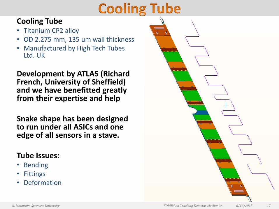
Cooling Tube• Titanium CP2 alloy• OD 2.275 mm, 135 um wall thickness• Manufactured by High Tech Tubes
Ltd. UK
Development by ATLAS (Richard French, University of Sheffield) and we have benefitted greatly from their expertise and help
Snake shape has been designed to run under all ASICs and one edge of all sensors in a stave.
Tube Issues:• Bending• Fittings• Deformation
6/16/2015R. Mountain, Syracuse University FORUM on Tracking Detector Mechanics 17
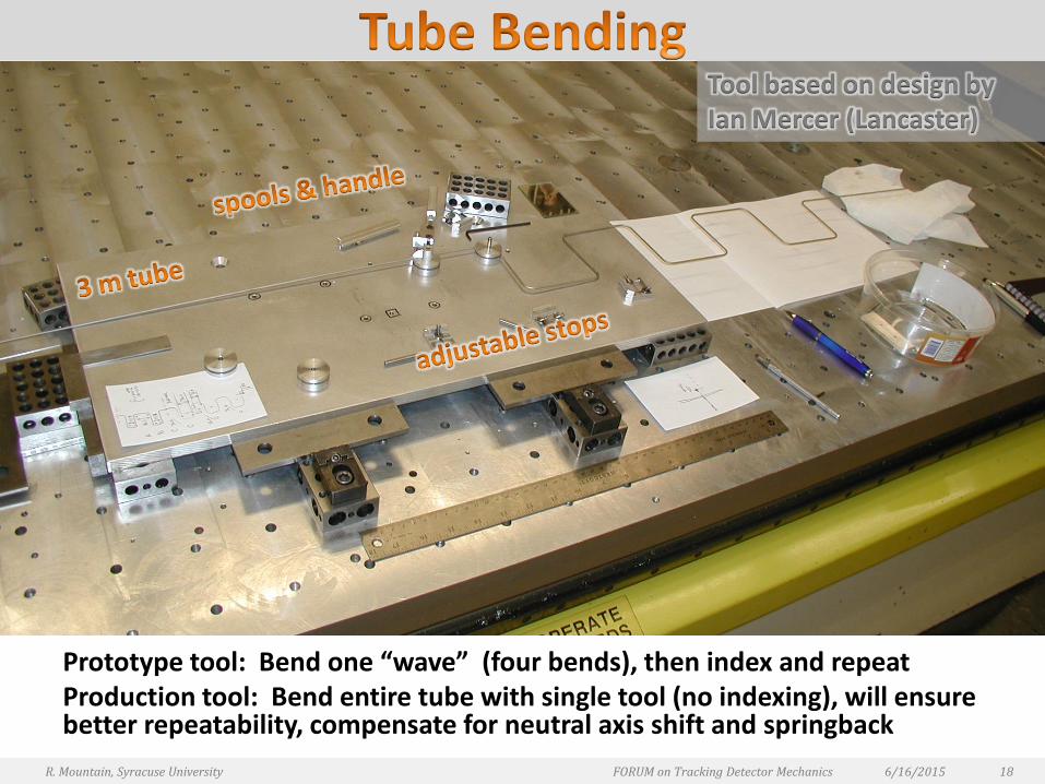
Prototype tool: Bend one “wave” (four bends), then index and repeatProduction tool: Bend entire tube with single tool (no indexing), will ensure better repeatability, compensate for neutral axis shift and springback
6/16/2015R. Mountain, Syracuse University FORUM on Tracking Detector Mechanics 18
Tool based on design by Ian Mercer (Lancaster)
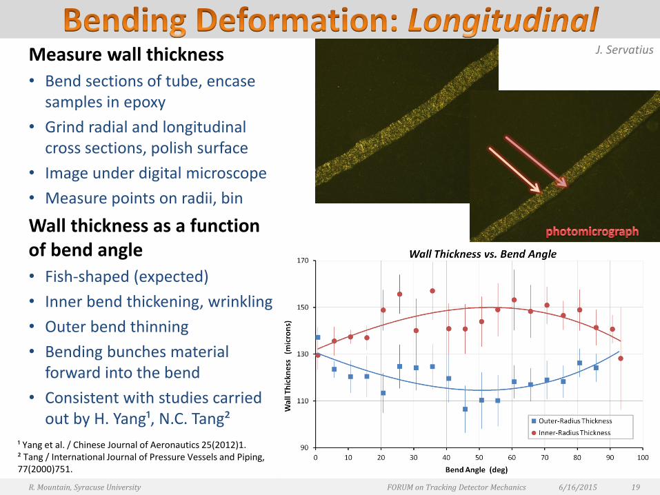
Measure wall thickness
• Bend sections of tube, encase samples in epoxy
• Grind radial and longitudinal cross sections, polish surface
• Image under digital microscope
• Measure points on radii, bin
Wall thickness as a function of bend angle
• Fish-shaped (expected)
• Inner bend thickening, wrinkling
• Outer bend thinning
• Bending bunches material forward into the bend
• Consistent with studies carried out by H. Yang¹, N.C. Tang²
6/16/2015R. Mountain, Syracuse University FORUM on Tracking Detector Mechanics 19
J. Servatius
¹ Yang et al. / Chinese Journal of Aeronautics 25(2012)1.² Tang / International Journal of Pressure Vessels and Piping, 77(2000)751.
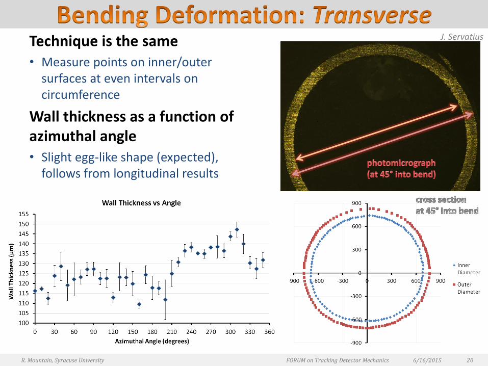
Technique is the same• Measure points on inner/outer
surfaces at even intervals on circumference
Wall thickness as a function of azimuthal angle • Slight egg-like shape (expected),
follows from longitudinal results
6/16/2015R. Mountain, Syracuse University FORUM on Tracking Detector Mechanics 20
J. Servatius
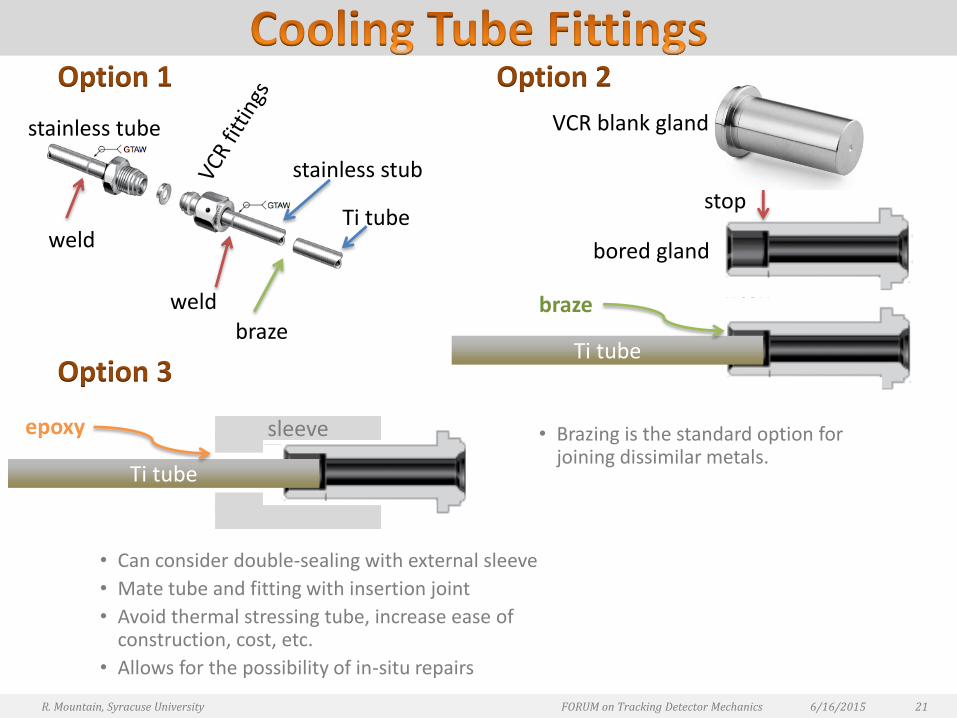
Option 1
Option 3
• Can consider double-sealing with external sleeve
• Mate tube and fitting with insertion joint
• Avoid thermal stressing tube, increase ease of construction, cost, etc.
• Allows for the possibility of in-situ repairs
Option 2
• Brazing is the standard option for joining dissimilar metals.
6/16/2015R. Mountain, Syracuse University FORUM on Tracking Detector Mechanics 21
stainless tube
Ti tube
weldbraze
weld
stainless stub
VCR blank gland
braze
Ti tube
stop
bored gland
Ti tube
epoxy sleeve
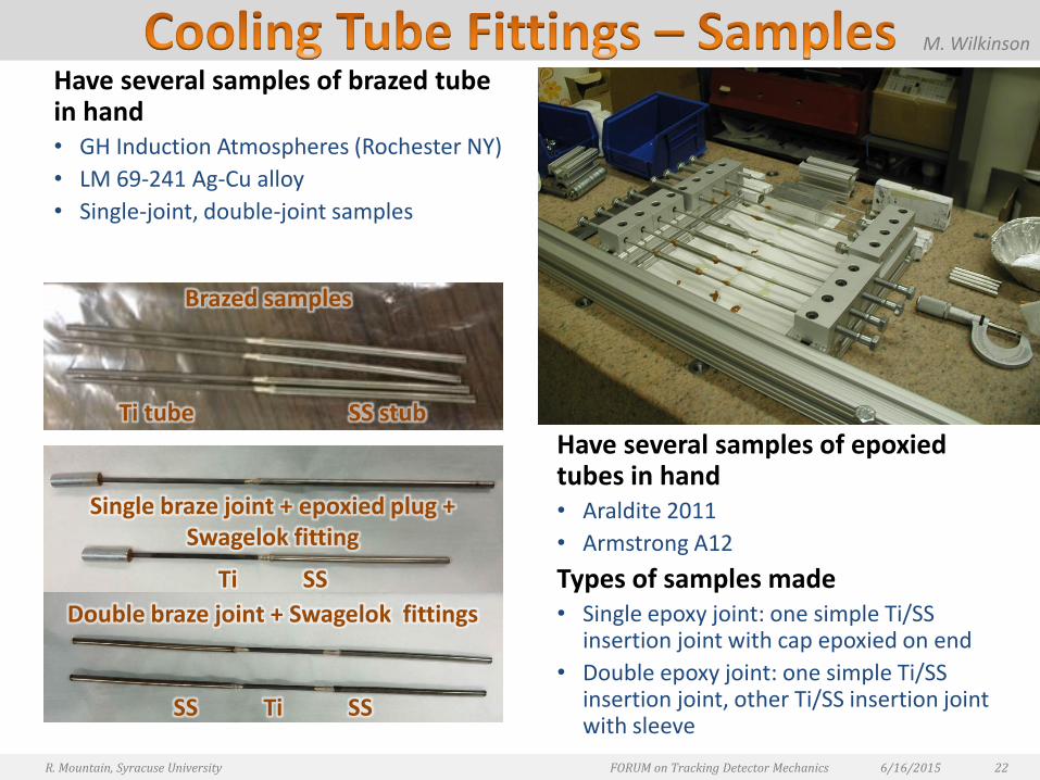
Have several samples of brazed tube in hand • GH Induction Atmospheres (Rochester NY)
• LM 69-241 Ag-Cu alloy
• Single-joint, double-joint samples
Have several samples of epoxied tubes in hand • Araldite 2011
• Armstrong A12
Types of samples made• Single epoxy joint: one simple Ti/SS
insertion joint with cap epoxied on end
• Double epoxy joint: one simple Ti/SS insertion joint, other Ti/SS insertion joint with sleeve
6/16/2015R. Mountain, Syracuse University FORUM on Tracking Detector Mechanics 22
Brazed samples
Ti tube SS stub
Double braze joint + Swagelok fittings
SS Ti SS
Single braze joint + epoxied plug + Swagelok fitting
Ti SS
M. Wilkinson
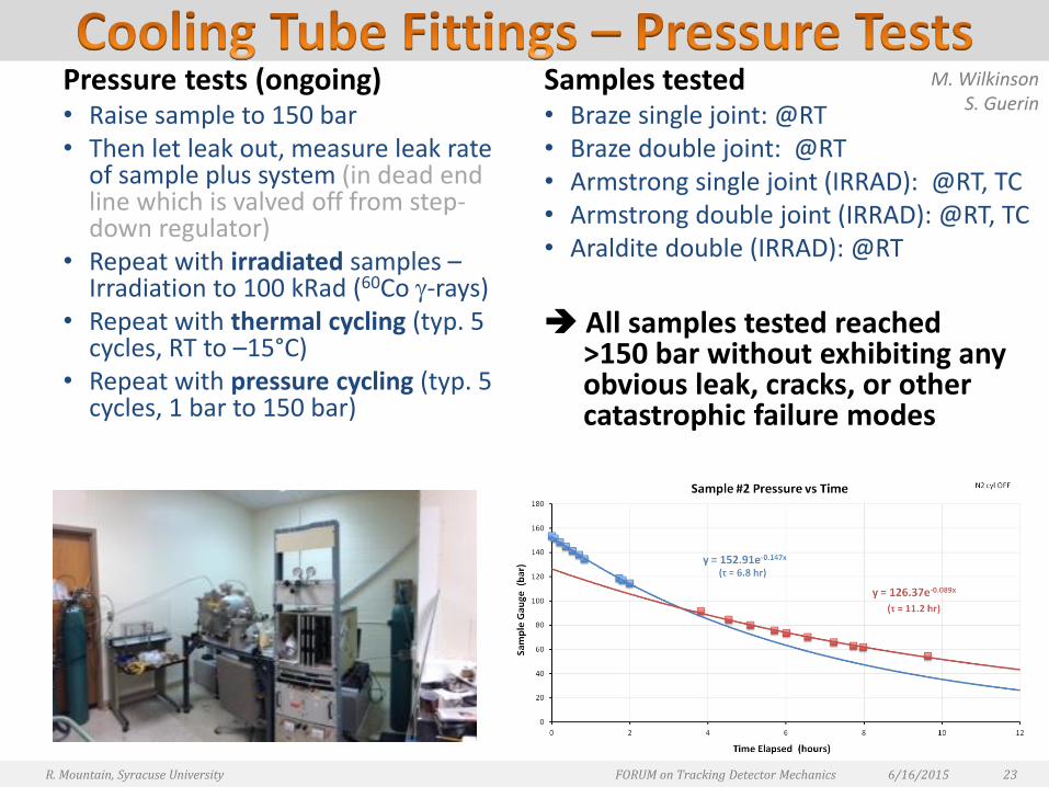
Pressure tests (ongoing)• Raise sample to 150 bar • Then let leak out, measure leak rate
of sample plus system (in dead end line which is valved off from step-down regulator)
• Repeat with irradiated samples –Irradiation to 100 kRad (60Co -rays)
• Repeat with thermal cycling (typ. 5 cycles, RT to –15°C)
• Repeat with pressure cycling (typ. 5 cycles, 1 bar to 150 bar)
Samples tested • Braze single joint: @RT• Braze double joint: @RT• Armstrong single joint (IRRAD): @RT, TC• Armstrong double joint (IRRAD): @RT, TC• Araldite double (IRRAD): @RT
All samples tested reached >150 bar without exhibiting any obvious leak, cracks, or other catastrophic failure modes
6/16/2015R. Mountain, Syracuse University FORUM on Tracking Detector Mechanics 23
M. WilkinsonS. Guerin
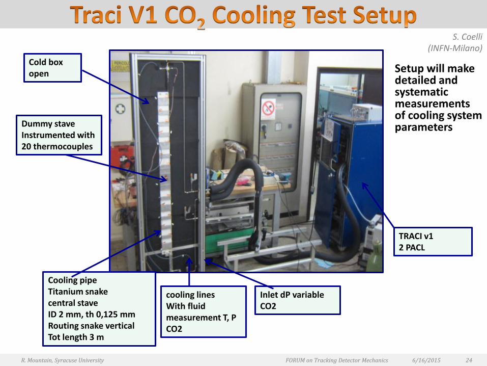
Setup will make detailed and systematic measurements of cooling system parameters
6/16/2015R. Mountain, Syracuse University FORUM on Tracking Detector Mechanics 24
Cold boxopen
Dummy staveInstrumented with 20 thermocouples
Cooling pipeTitanium snakecentral staveID 2 mm, th 0,125 mmRouting snake verticalTot length 3 m
cooling linesWith fluid measurement T, P CO2
TRACI v12 PACL
Inlet dP variable CO2
S. Coelli(INFN-Milano)
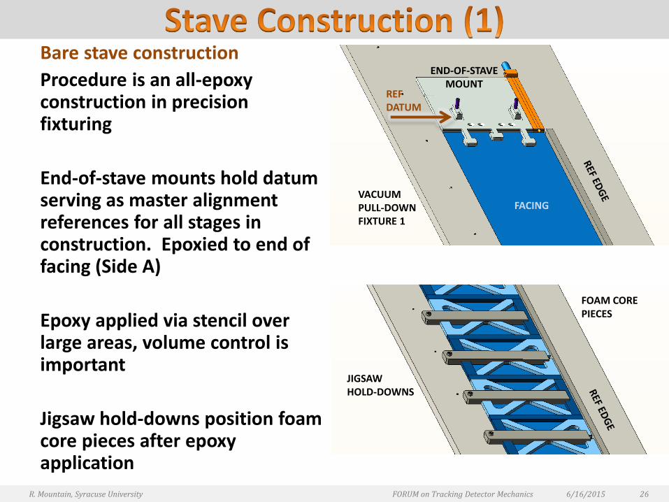
Bare stave construction
Procedure is an all-epoxy construction in precision fixturing
End-of-stave mounts hold datum serving as master alignment references for all stages in construction. Epoxied to end of facing (Side A)
Epoxy applied via stencil over large areas, volume control is important
Jigsaw hold-downs position foam core pieces after epoxy application
6/16/2015R. Mountain, Syracuse University FORUM on Tracking Detector Mechanics 26
END-OF-STAVEMOUNT
FACING
REFDATUM
VACUUMPULL-DOWNFIXTURE 1
FOAM COREPIECES
JIGSAWHOLD-DOWNS
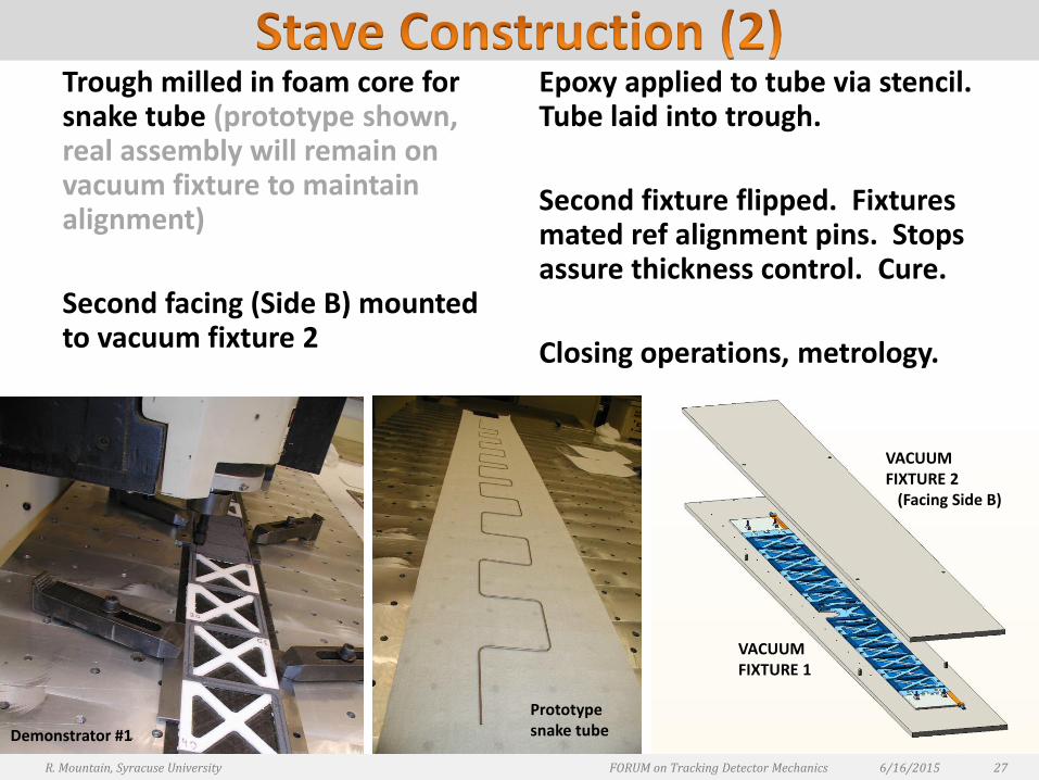
Trough milled in foam core for snake tube (prototype shown, real assembly will remain on vacuum fixture to maintain alignment)
Second facing (Side B) mounted to vacuum fixture 2
Epoxy applied to tube via stencil. Tube laid into trough.
Second fixture flipped. Fixtures mated ref alignment pins. Stops assure thickness control. Cure.
Closing operations, metrology.
6/16/2015R. Mountain, Syracuse University FORUM on Tracking Detector Mechanics 27
VACUUMFIXTURE 2
(Facing Side B)
VACUUMFIXTURE 1
Demonstrator #1
Prototype snake tube

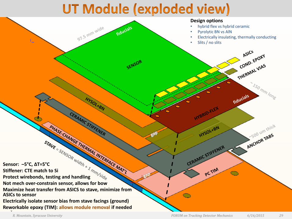
Sensor: –5°C, ΔT=5°C Stiffener: CTE match to SiProtect wirebonds, testing and handlingNot mech over-constrain sensor, allows for bowMaximize heat transfer from ASICS to stave, minimize from ASICs to sensorElectrically isolate sensor bias from stave facings (ground)Reworkable epoxy (TIM): allows module removal if needed
Design options• hybrid flex vs hybrid ceramic• Pyrolytic BN vs AlN• Electrically insulating, thermally conducting• Slits / no slits
6/16/2015 29R. Mountain, Syracuse University FORUM on Tracking Detector Mechanics
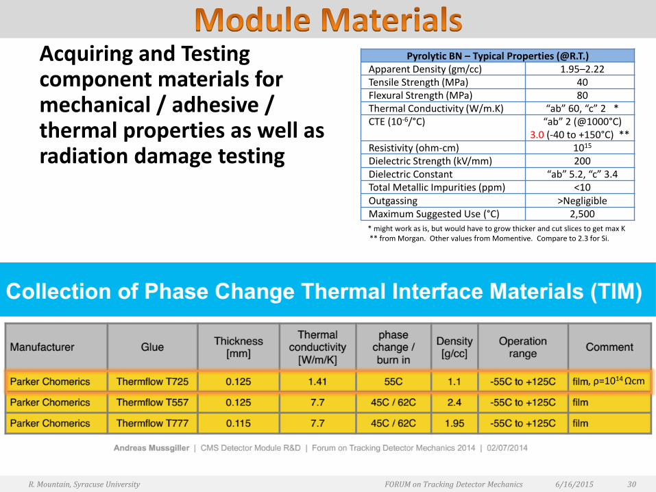
Acquiring and Testing component materials for mechanical / adhesive / thermal properties as well as radiation damage testing
6/16/2015R. Mountain, Syracuse University FORUM on Tracking Detector Mechanics 30
Pyrolytic BN – Typical Properties (@R.T.)Apparent Density (gm/cc) 1.95–2.22Tensile Strength (MPa) 40 Flexural Strength (MPa) 80 Thermal Conductivity (W/m.K) “ab” 60, “c” 2 *CTE (10-6/°C) “ab” 2 (@1000°C)
3.0 (-40 to +150°C) **Resistivity (ohm-cm) 1015
Dielectric Strength (kV/mm) 200Dielectric Constant “ab” 5.2, “c” 3.4Total Metallic Impurities (ppm) <10Outgassing >NegligibleMaximum Suggested Use (°C) 2,500
* might work as is, but would have to grow thicker and cut slices to get max K** from Morgan. Other values from Momentive. Compare to 2.3 for Si.
, ρ=1014 Ωcm
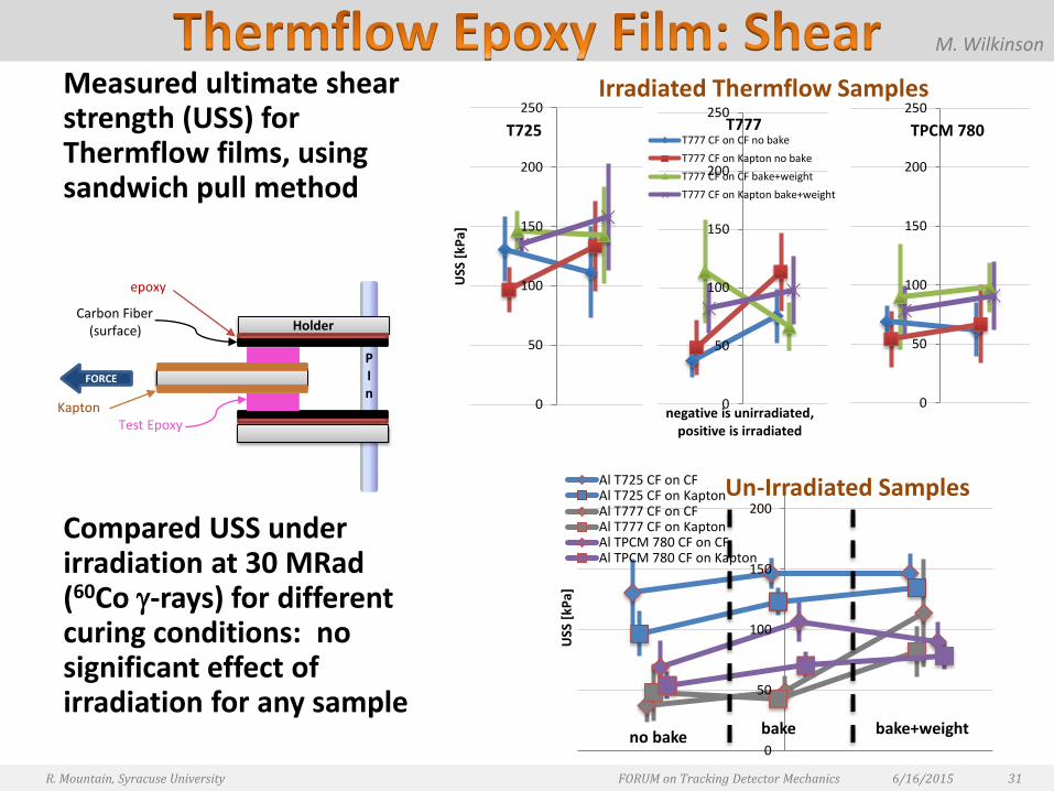
Measured ultimate shear strength (USS) for Thermflow films, using sandwich pull method
Compared USS under irradiation at 30 MRad(60Co -rays) for different curing conditions: no significant effect of irradiation for any sample
6/16/2015R. Mountain, Syracuse University FORUM on Tracking Detector Mechanics 31
0
50
100
150
200
USS
[kP
a]
Un-Irradiated SamplesAl T725 CF on CFAl T725 CF on KaptonAl T777 CF on CFAl T777 CF on KaptonAl TPCM 780 CF on CFAl TPCM 780 CF on Kapton
no bake bake bake+weight
0
50
100
150
200
250
USS
[kP
a]
0
50
100
150
200
250
negative is unirradiated, positive is irradiated
T777 CF on CF no bake
T777 CF on Kapton no bake
T777 CF on CF bake+weight
T777 CF on Kapton bake+weight
0
50
100
150
200
250Irradiated Thermflow Samples
T725 TPCM 780T777
PIn
Holder
FORCE
epoxy
Carbon Fiber(surface)
Test EpoxyKapton
M. Wilkinson
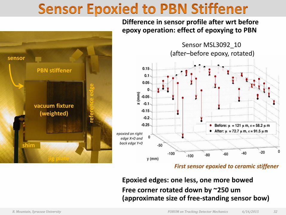
Difference in sensor profile after wrt before epoxy operation: effect of epoxying to PBN
Epoxied edges: one less, one more bowed
Free corner rotated down by ~250 um (approximate size of free-standing sensor bow)
6/16/2015R. Mountain, Syracuse University FORUM on Tracking Detector Mechanics 32
PBN stiffener
vacuum fixture(weighted)
refe
ren
ce e
dge
sensor
shim
jig plate
epoxied on right edge X=0 and
back edge Y=0
Sensor MSL3092_10 (after–before epoxy, rotated)
First sensor epoxied to ceramic stiffener

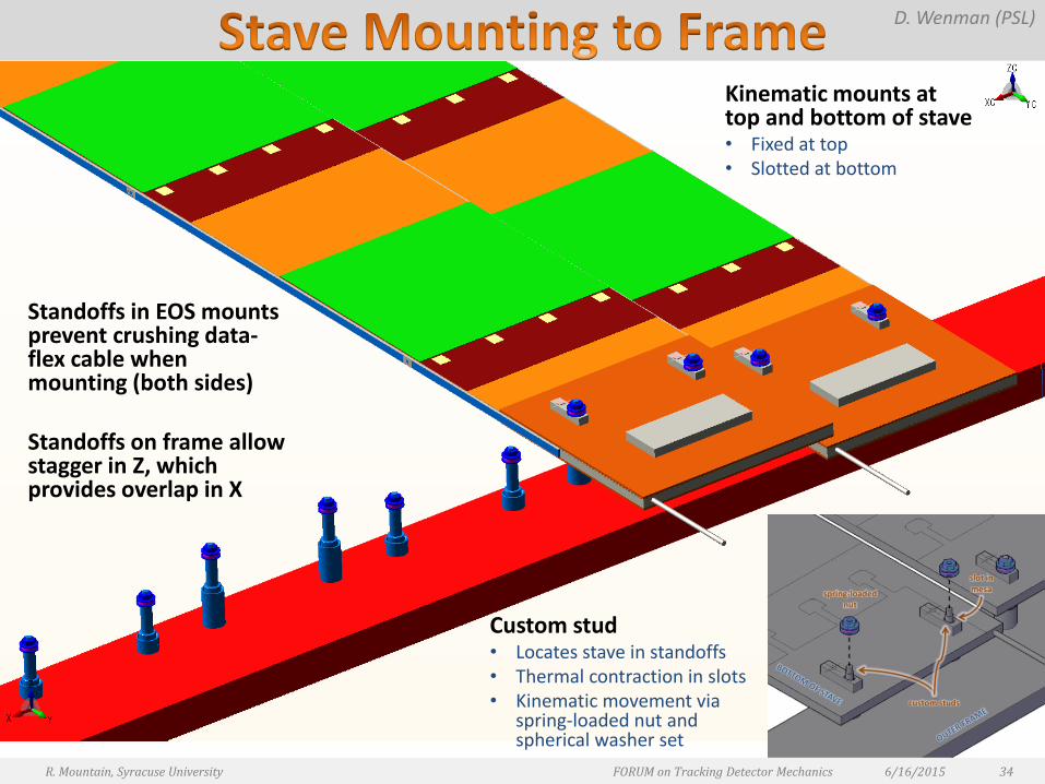
Standoffs in EOS mounts prevent crushing data-flex cable when mounting (both sides)
Standoffs on frame allow stagger in Z, which provides overlap in X
Custom stud • Locates stave in standoffs• Thermal contraction in slots• Kinematic movement via
spring-loaded nut and spherical washer set
6/16/2015R. Mountain, Syracuse University FORUM on Tracking Detector Mechanics 34
D. Wenman (PSL)
Kinematic mounts at top and bottom of stave• Fixed at top• Slotted at bottom
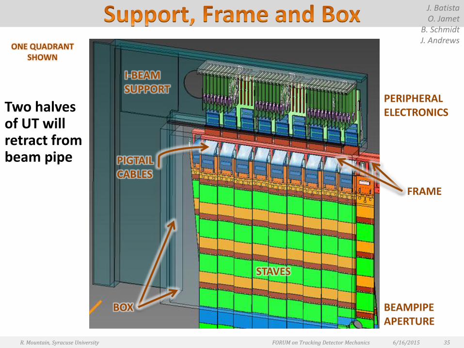
Two halves of UT will retract from beam pipe
6/16/2015R. Mountain, Syracuse University FORUM on Tracking Detector Mechanics 35
J. BatistaO. Jamet
B. SchmidtJ. Andrews
ONE QUADRANT SHOWN
BOX
FRAME
STAVES
I-BEAMSUPPORT
PERIPHERALELECTRONICS
PIGTAILCABLES
BEAMPIPEAPERTURE

LHCb Upstream Tracker is comprised of four planes of silicon sensors which are supported by integrated stave structures
The UT stave has been designed using FEA model techniques, prototypes, component testing, etc.
Many components have been tested and qualified, some work still remains
Module design has been refined although several issues remain
Frame and box design is progressing, although the end of stave region is dense and challenging
Phase 1 construction planned to start end Summer 2015 • Bare stave construction
• Will soon freeze all mechanical parameters and design choices necessary to begin construction
• This will allow us to construct all bare staves, which frees manpower and resources for subsequent phases
Phase 2 construction will start when data-flex cables become available
Phase 3 construction will begin when modules (sensors, hybrids) are available
Assemble at CERN in 2018
Install in IP8 in 2019
6/16/2015 37R. Mountain, Syracuse University FORUM on Tracking Detector Mechanics
6/16/2015R. Mountain, Syracuse University FORUM on Tracking Detector Mechanics 38
6/16/2015R. Mountain, Syracuse University FORUM on Tracking Detector Mechanics 39
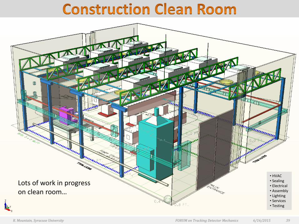
Lots of work in progress on clean room…
• HVAC• Sealing• Electrical• Assembly• Lighting • Services • Testing