Embed Size (px)
Citation preview
Copyright reserved Please turn over
MARKS: 200 TIME: 3 hours
This question paper consists of 19 pages, a 5-page formula sheet and 1 answer
sheet.
GRADE 12
MECHANICAL TECHNOLOGY
FEBRUARY/MARCH 2012
NATIONAL SENIOR CERTIFICATE
GRADE 12
Mechanical Technology 2 DBE/Feb.–Mar. 2012 NSC
Copyright reserved Please turn over
INSTRUCTIONS AND INFORMATION 1. Write your centre number and examination number in the spaces provided on
the ANSWER BOOK and the ANSWER SHEET.
2. Read ALL the questions carefully. 3. Answer ALL the questions. 4. Answer the questions in QUESTION 1 on the attached ANSWER SHEET.
Place the completed ANSWER SHEET in the ANSWER BOOK.
5. Number the answers correctly according to the numbering system used in this
question paper.
6. Start EACH question on a NEW page. 7. Show ALL calculations and units. Round off final answers to TWO decimal
places.
8. Candidates may use non-programmable scientific calculators and drawing
instruments.
9. The value of the gravitational force constant should be taken as 10 m/s2. 10. All dimensions are in millimetres, unless stated otherwise in the question. 11. Write neatly and legibly. 12. Use the criteria below to assist you in managing your time.
QUESTION ASSESSMENT STANDARDS CONTENT MARKS TIME
1 1–9 Multiple-choice Questions 20 18 minutes
2 2 Tools and Equipment 20 18 minutes
3 3 Materials 20 18 minutes
4 1, 4 and 5 Safety, Terminology and Joining Methods 50 45
minutes
5 7 and 9 Maintenance and Turbines 40 36 minutes
6 6 and 8 Forces, Systems and Control 50 45 minutes
TOTAL 200 180 minutes

Mechanical Technology 3 DBE/Feb.–Mar. 2012 NSC
Copyright reserved Please turn over
QUESTION 1: MULTIPLE-CHOICE QUESTIONS
Various options are provided as possible answers to the following questions. Choose the answer and make a cross (X) in the block (A–D) next to the question number (1.1–1.20) on the attached ANSWER SHEET. EXAMPLE:
1.1 Which ONE of the following safety measures applies to a milling machine? A
B C D
The material to be sawn must be clamped securely in the vice. Always remove the key from the chuck. Never reach over or near the rotating cutter. Make sure that the blades are tightened properly.
(1)
1.2 Which ONE of the following safety procedures relates to a moments-and-
forces tester?
A
B C D
Remove primary coil lead to prevent sparks from occurring. When coolant is contaminated, it must be changed. Make sure that the blades are tightened properly. Make sure that the object to be tested is firmly secured.
(1)
1.3 What is the function of a torsion tester? A
B C D
It measures the resistance of a material to a static force. It measures the flow of exhaust gases. It measures the twisting action in a member caused by two opposing moments along the longitudinal axis of the member. It measures the current flowing in a circuit.
(1)
1.4 Shielding the arc and molten pool from atmospheric gases is the function of
the …
A
B C D
inert gas. outlet gas. inlet gas. air-fuel mixture.
(1)
1.21 A B C D
Mechanical Technology 4 DBE/Feb.–Mar. 2012 NSC
Copyright reserved Please turn over
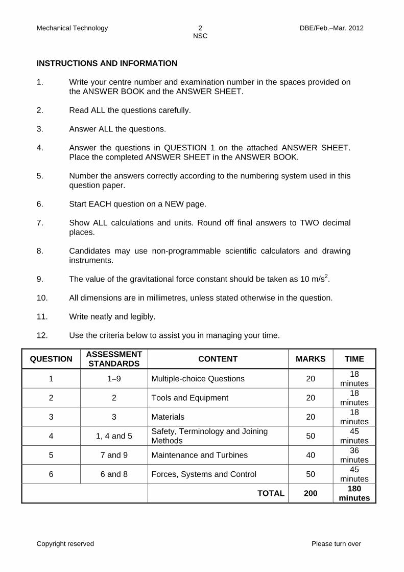
1.5 What is the purpose of using flux when soft-soldering as shown in
FIGURE 1.1?
FIGURE 1.1 A
B C D
Ensures that there are no weld craters Ensures that the heated surface is smooth Ensures that the soldered joint is tough Ensures chemical cleanliness of the heated surface
(1)
1.6 What are thermoplastic materials? A
B C D
Materials that can be stretched and return to their original shape Materials that soften under heat and become hard when cooled Materials that cannot be reshaped by heating Materials that form a rigid shape under pressure
(1)
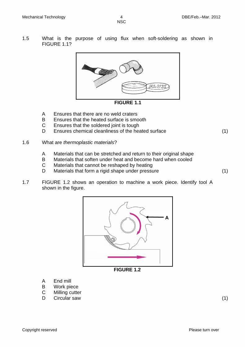
1.7 FIGURE 1.2 shows an operation to machine a work piece. Identify tool A
shown in the figure.
FIGURE 1.2 A
B C D
End mill Work piece Milling cutter Circular saw
(1)
A
Mechanical Technology 5 DBE/Feb.–Mar. 2012 NSC
Copyright reserved Please turn over
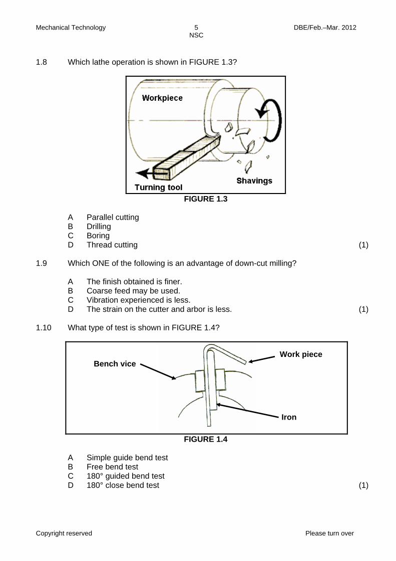
1.8 Which lathe operation is shown in FIGURE 1.3?
FIGURE 1.3 A
B C D
Parallel cutting Drilling Boring Thread cutting
(1)
1.9 Which ONE of the following is an advantage of down-cut milling? A
B C D
The finish obtained is finer. Coarse feed may be used. Vibration experienced is less. The strain on the cutter and arbor is less.
(1)
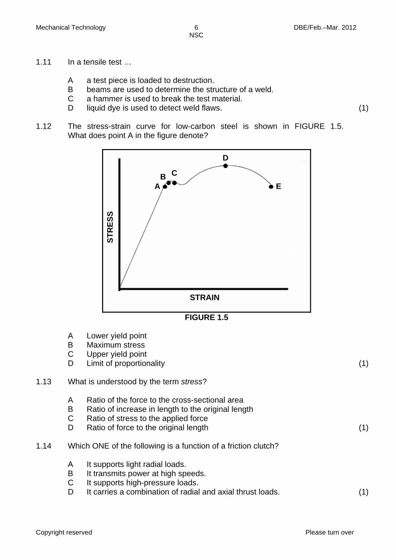
1.10 What type of test is shown in FIGURE 1.4?
FIGURE 1.4 A
B C D
Simple guide bend test Free bend test 180° guided bend test 180° close bend test
(1)
Bench vice Work piece
Iron
Mechanical Technology 6 DBE/Feb.–Mar. 2012 NSC
Copyright reserved Please turn over
1.11 In a tensile test … A
B C D
a test piece is loaded to destruction. beams are used to determine the structure of a weld. a hammer is used to break the test material. liquid dye is used to detect weld flaws.
(1)
1.12 The stress-strain curve for low-carbon steel is shown in FIGURE 1.5.
What does point A in the figure denote?
FIGURE 1.5 A
B C D
Lower yield point Maximum stress Upper yield point Limit of proportionality
(1)
1.13 What is understood by the term stress? A
B C D
Ratio of the force to the cross-sectional area Ratio of increase in length to the original length Ratio of stress to the applied force Ratio of force to the original length
(1)
1.14 Which ONE of the following is a function of a friction clutch? A
B C D
It supports light radial loads. It transmits power at high speeds. It supports high-pressure loads. It carries a combination of radial and axial thrust loads.
(1)
A B C
D
E
STRAIN
STR
ESS
Mechanical Technology 7 DBE/Feb.–Mar. 2012 NSC
Copyright reserved Please turn over
1.15 Which ONE of the following is an advantage of a chain-and-sprocket
transmission system?
A
B C D
Low in cost Needs no lubrication Smooth operation Slip-free drive
(1)
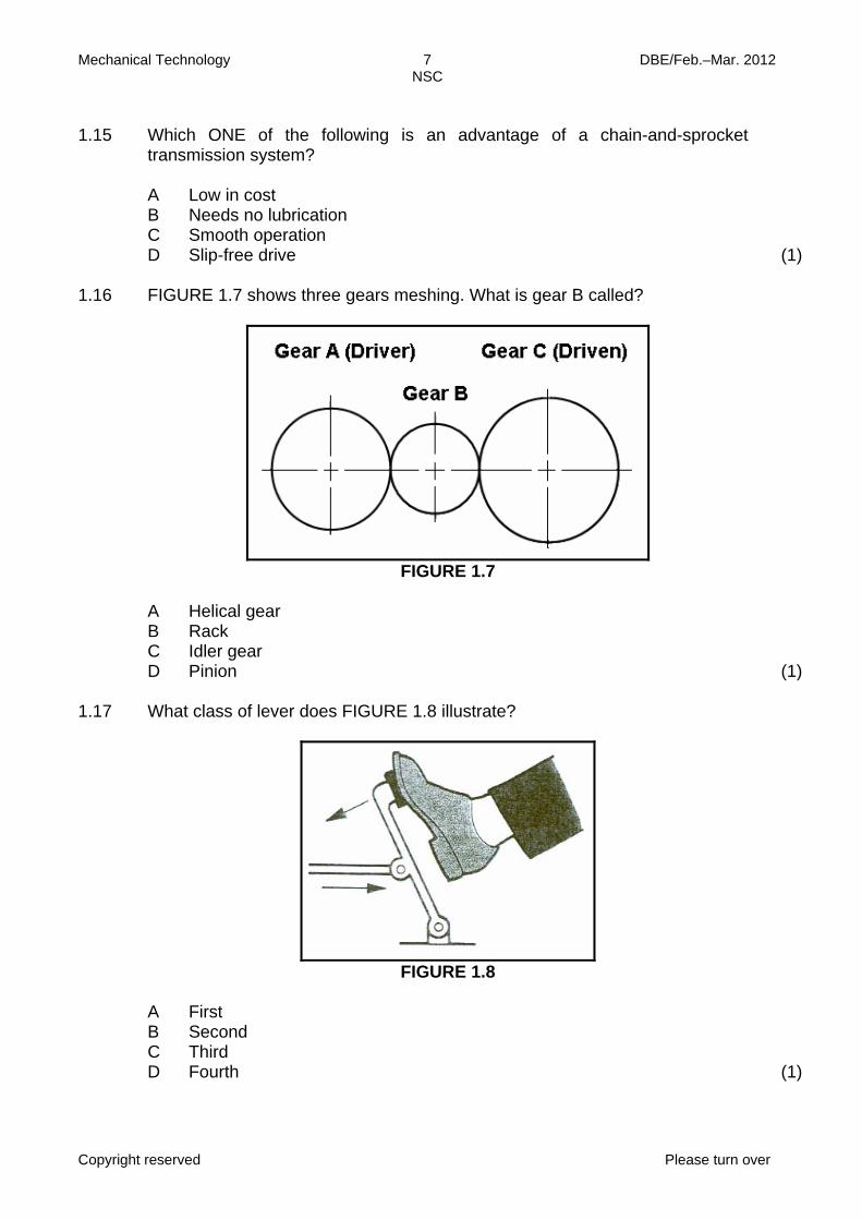
1.16 FIGURE 1.7 shows three gears meshing. What is gear B called?
FIGURE 1.7 A
B C D
Helical gear Rack Idler gear Pinion
(1)
1.17 What class of lever does FIGURE 1.8 illustrate?
FIGURE 1.8
A
B C D
First Second Third Fourth
(1)

Mechanical Technology 8 DBE/Feb.–Mar. 2012 NSC
Copyright reserved Please turn over
1.18 Identify the mechanism shown in FIGURE 1.9.
FIGURE 1.9
A
B C D
Ratchet and pawl Worm and worm wheel Wheel and pinion Driver and driven
(1)
1.19 What is the function of the waste gate in a turbo charger? A
B C D
Releases excess pressure Releases excess moisture Releases excess heat Releases excess oil (1)
1.20 What will the volumetric efficiency be if a 100 mm3 blower displaces 79 mm3
per revolution?
A
B C D
100% 79% 21% 179%
(1) [20]
Mechanical Technology 9 DBE/Feb.–Mar. 2012 NSC
Copyright reserved Please turn over
QUESTION 2: TOOLS AND EQUIPMENT 2.1 Mr Zungu had conducted a cylinder-leakage test and obtained certain results.
State ONE possible result and the fault on the cylinder.
(2)
2.2 A gas analyser is an important piece of equipment as it is used to analyse the exhaust gases of an internal combustion engine. Give TWO reasons for a high CO reading.
(2)
2.3 State the purpose for the following tests done on metals: 2.3.1 Tensile test (2) 2.3.2 Beam-bending test (2) 2.4 Name TWO types of hardness testers. (2) 2.5 Name THREE functions of a multimeter. (3)
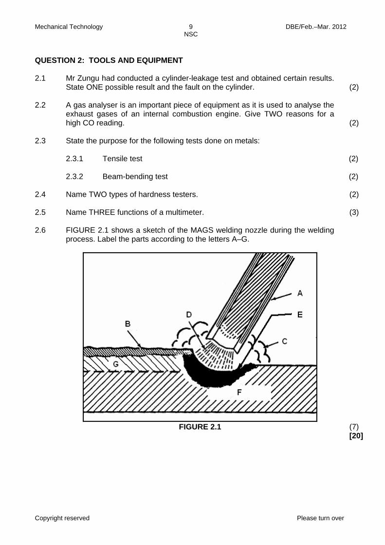
2.6 FIGURE 2.1 shows a sketch of the MAGS welding nozzle during the welding
process. Label the parts according to the letters A–G.
FIGURE 2.1 (7) [20]
Mechanical Technology 10 DBE/Feb.–Mar. 2012 NSC
Copyright reserved Please turn over
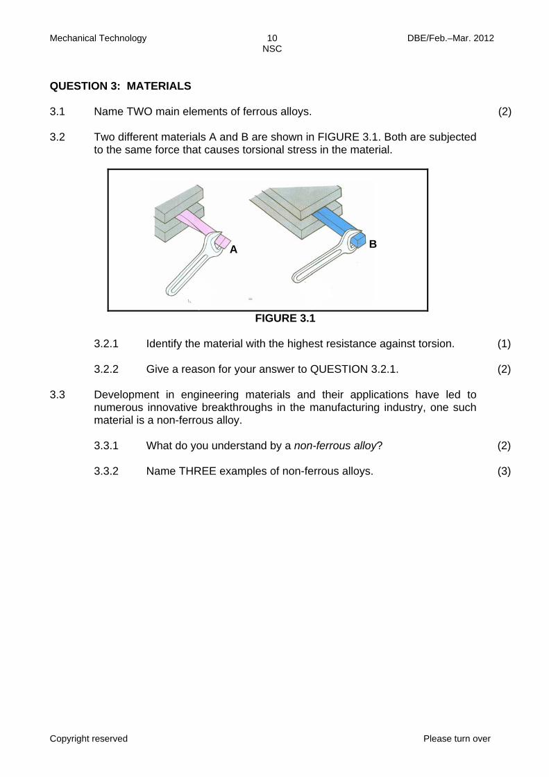
QUESTION 3: MATERIALS 3.1 Name TWO main elements of ferrous alloys. (2) 3.2 Two different materials A and B are shown in FIGURE 3.1. Both are subjected
to the same force that causes torsional stress in the material.
FIGURE 3.1 3.2.1 Identify the material with the highest resistance against torsion. (1) 3.2.2 Give a reason for your answer to QUESTION 3.2.1. (2) 3.3 Development in engineering materials and their applications have led to
numerous innovative breakthroughs in the manufacturing industry, one such material is a non-ferrous alloy.
3.3.1 What do you understand by a non-ferrous alloy? (2) 3.3.2 Name THREE examples of non-ferrous alloys. (3)
A B
Mechanical Technology 11 DBE/Feb.–Mar. 2012 NSC
Copyright reserved Please turn over
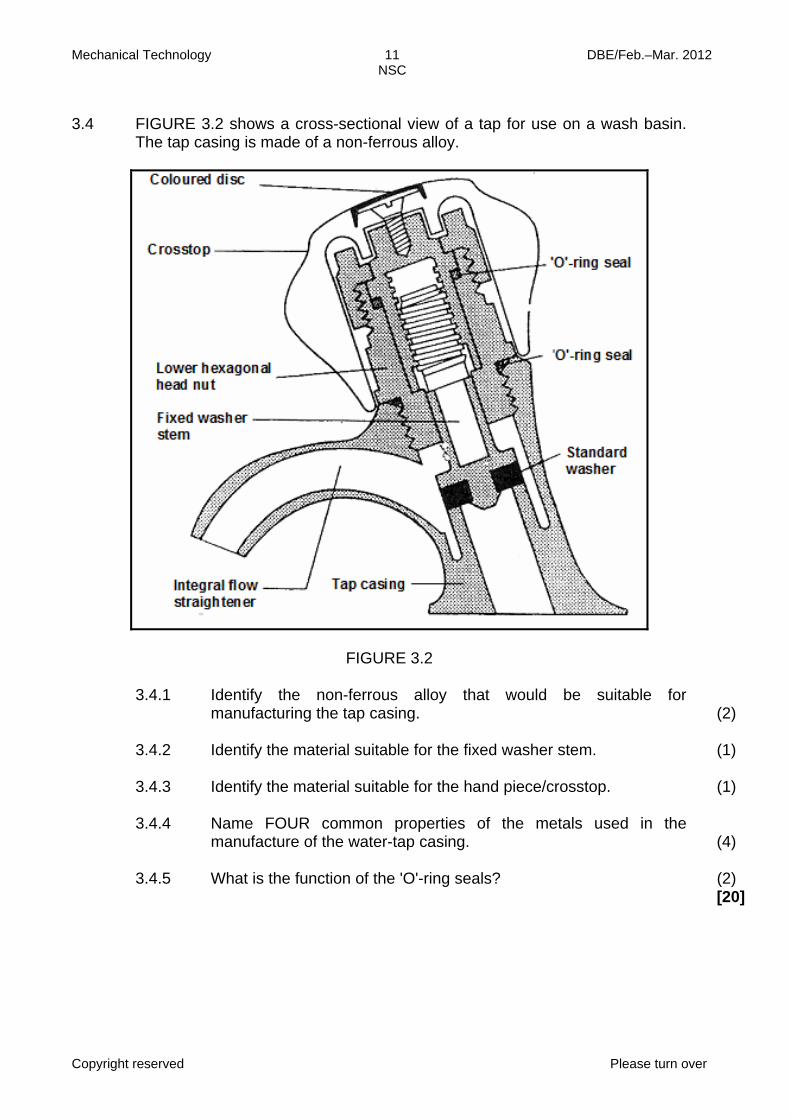
3.4 FIGURE 3.2 shows a cross-sectional view of a tap for use on a wash basin.
The tap casing is made of a non-ferrous alloy.
FIGURE 3.2
3.4.1 Identify the non-ferrous alloy that would be suitable for manufacturing the tap casing.
(2)
3.4.2 Identify the material suitable for the fixed washer stem. (1) 3.4.3 Identify the material suitable for the hand piece/crosstop. (1) 3.4.4 Name FOUR common properties of the metals used in the
manufacture of the water-tap casing. (4)
3.4.5 What is the function of the 'O'-ring seals? (2)
[20]
Mechanical Technology 12 DBE/Feb.–Mar. 2012 NSC
Copyright reserved Please turn over
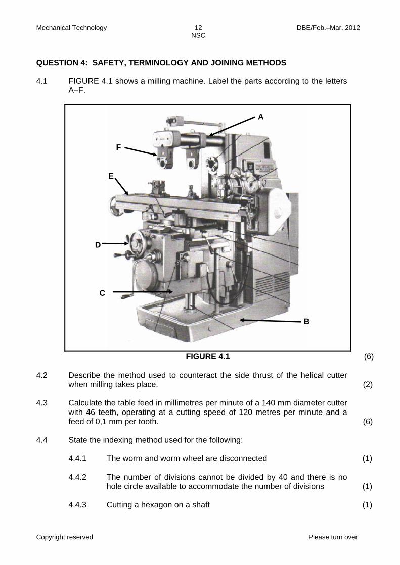
QUESTION 4: SAFETY, TERMINOLOGY AND JOINING METHODS 4.1 FIGURE 4.1 shows a milling machine. Label the parts according to the letters
A–F.
FIGURE 4.1 (6) 4.2 Describe the method used to counteract the side thrust of the helical cutter
when milling takes place.
(2) 4.3 Calculate the table feed in millimetres per minute of a 140 mm diameter cutter
with 46 teeth, operating at a cutting speed of 120 metres per minute and a feed of 0,1 mm per tooth.
(6) 4.4 State the indexing method used for the following: 4.4.1
4.4.2 4.4.3
The worm and worm wheel are disconnected The number of divisions cannot be divided by 40 and there is no hole circle available to accommodate the number of divisions Cutting a hexagon on a shaft
(1) (1) (1)
A
B
D
C
E
F
Mechanical Technology 13 DBE/Feb.–Mar. 2012 NSC
Copyright reserved Please turn over
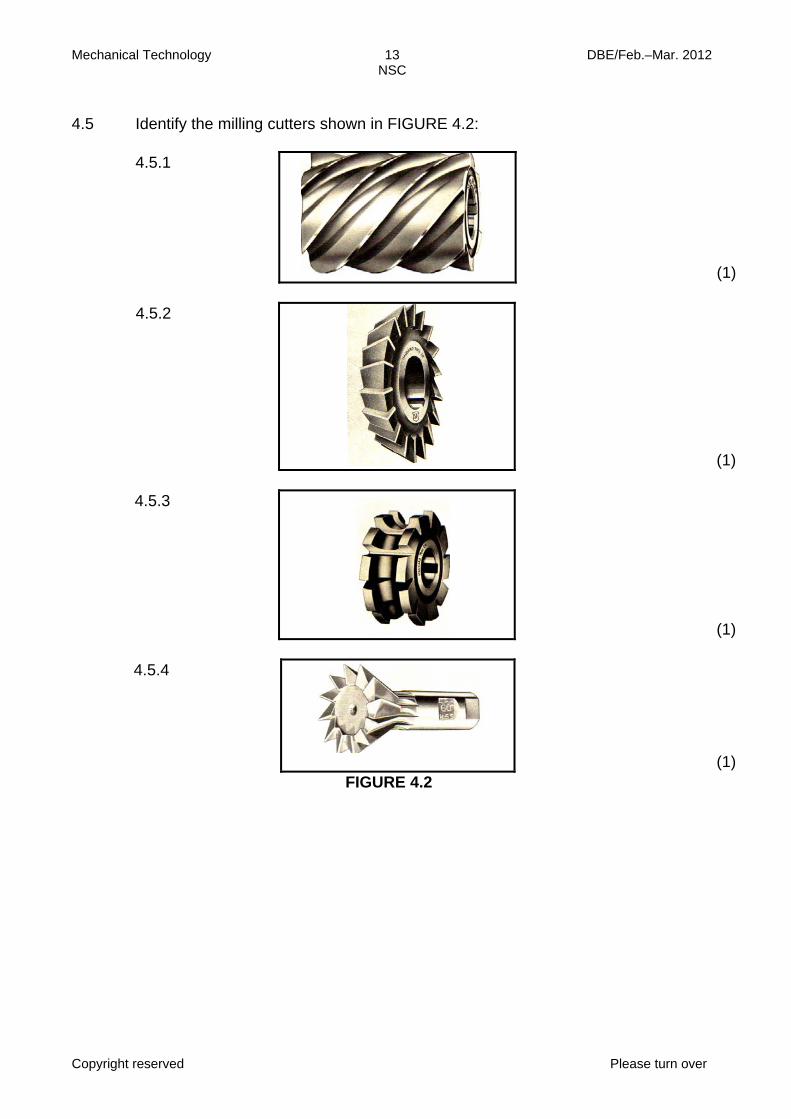
4.5 Identify the milling cutters shown in FIGURE 4.2: 4.5.1
(1)
4.5.2
(1)
4.5.3
(1)
4.5.4
(1) FIGURE 4.2
Mechanical Technology 14 DBE/Feb.–Mar. 2012 NSC
Copyright reserved Please turn over
4.6 Two gears that mesh with each other need to be manufactured. The one gear
should have 56 teeth with a PCD of 126 mm, while the other gear should have 39 teeth with a PCD of 87,75 mm.
Determine, by means of calculations, the following: 4.6.1 The module of the small gear (2) 4.6.2 The module of the large gear (2) 4.6.3 The outside diameter of the large gear (3) 4.6.4 The dedendum of the large gear (2) 4.6.5 The clearance of the large gear (2) 4.6.6 The indexing needed to cut the large gear (3) 4.7 Name THREE types of non-destructive tests that can be performed on welded
joints.
(3) 4.8 Name TWO possible causes for the following weld defects: 4.8.1 Insufficient penetration (2) 4.8.2 Porosity (2) 4.8.3 Welding craters (2) 4.9 Name TWO safety measures to be observed when using the Brinell hardness
tester.
(2) 4.10 Name FOUR safety precautions to be observed when using a bearing and
gear puller.
(4) [50]
Mechanical Technology 15 DBE/Feb.–Mar. 2012 NSC
Copyright reserved Please turn over
QUESTION 5: MAINTENANCE AND TURBINES 5.1 Oil filters are used to clean the engine oil so as to prolong the lifespan of an
engine. Explain in point form how you will remove and fit a new oil filter to an engine when servicing a motor vehicle.
(5)
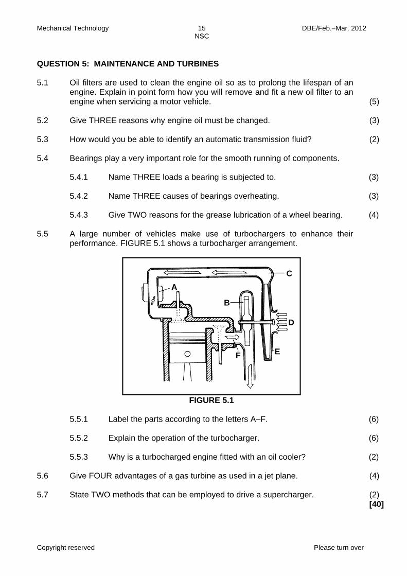
5.2 Give THREE reasons why engine oil must be changed. (3) 5.3 How would you be able to identify an automatic transmission fluid? (2) 5.4 Bearings play a very important role for the smooth running of components. 5.4.1 Name THREE loads a bearing is subjected to. (3) 5.4.2 Name THREE causes of bearings overheating. (3) 5.4.3 Give TWO reasons for the grease lubrication of a wheel bearing. (4) 5.5 A large number of vehicles make use of turbochargers to enhance their
performance. FIGURE 5.1 shows a turbocharger arrangement.
FIGURE 5.1
5.5.1 Label the parts according to the letters A–F. (6) 5.5.2 Explain the operation of the turbocharger. (6) 5.5.3 Why is a turbocharged engine fitted with an oil cooler? (2) 5.6 Give FOUR advantages of a gas turbine as used in a jet plane. (4) 5.7 State TWO methods that can be employed to drive a supercharger. (2)
[40]
E
C A
F
B
D
Mechanical Technology 16 DBE/Feb.–Mar. 2012 NSC
Copyright reserved Please turn over
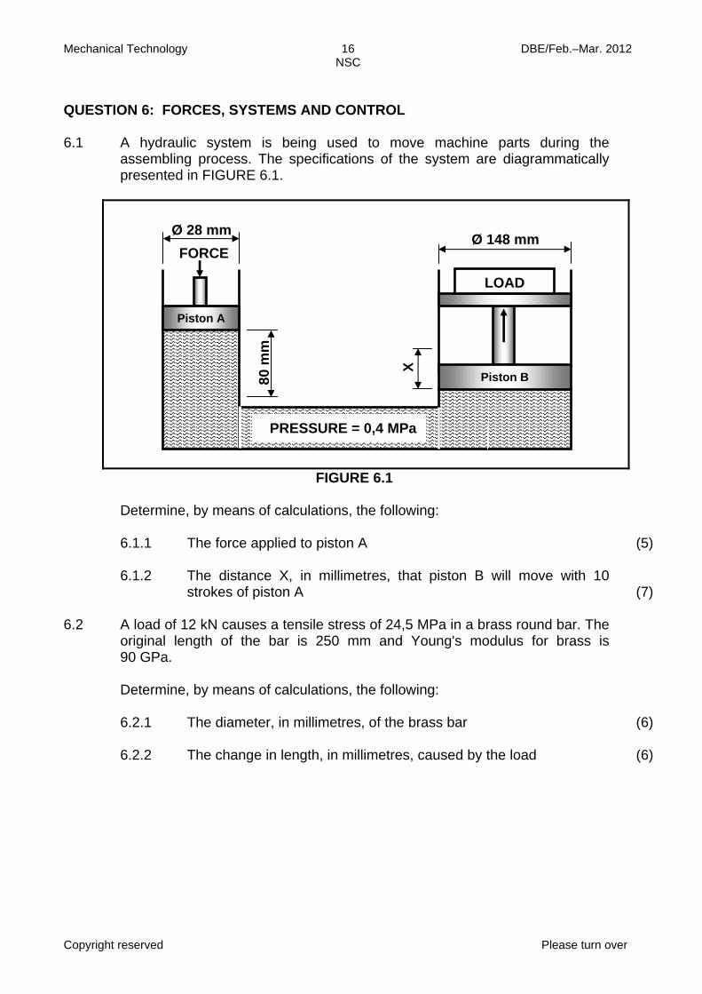
QUESTION 6: FORCES, SYSTEMS AND CONTROL 6.1 A hydraulic system is being used to move machine parts during the
assembling process. The specifications of the system are diagrammatically presented in FIGURE 6.1.
FIGURE 6.1 Determine, by means of calculations, the following: 6.1.1 The force applied to piston A (5) 6.1.2 The distance X, in millimetres, that piston B will move with 10
strokes of piston A (7) 6.2 A load of 12 kN causes a tensile stress of 24,5 MPa in a brass round bar. The
original length of the bar is 250 mm and Young's modulus for brass is 90 GPa.
Determine, by means of calculations, the following:
6.2.1 The diameter, in millimetres, of the brass bar (6) 6.2.2 The change in length, in millimetres, caused by the load (6)
X
Piston A
Piston B
LOAD
Ø 148 mm 80
mm
Ø 28 mm FORCE
PRESSURE = 0,4 MPa
Mechanical Technology 17 DBE/Feb.–Mar. 2012 NSC
Copyright reserved Please turn over
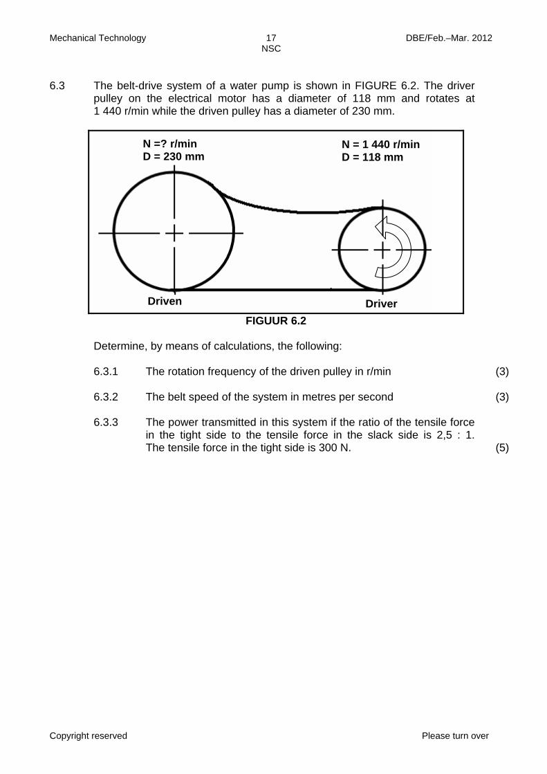
6.3 The belt-drive system of a water pump is shown in FIGURE 6.2. The driver
pulley on the electrical motor has a diameter of 118 mm and rotates at 1 440 r/min while the driven pulley has a diameter of 230 mm.
FIGUUR 6.2 Determine, by means of calculations, the following: 6.3.1
6.3.2 6.3.3
The rotation frequency of the driven pulley in r/min The belt speed of the system in metres per second The power transmitted in this system if the ratio of the tensile force in the tight side to the tensile force in the slack side is 2,5 : 1. The tensile force in the tight side is 300 N.
(3) (3) (5)
N =? r/min D = 230 mm
N = 1 440 r/min D = 118 mm
Driven Driver
Mechanical Technology 18 DBE/Feb.–Mar. 2012 NSC
Copyright reserved Please turn over
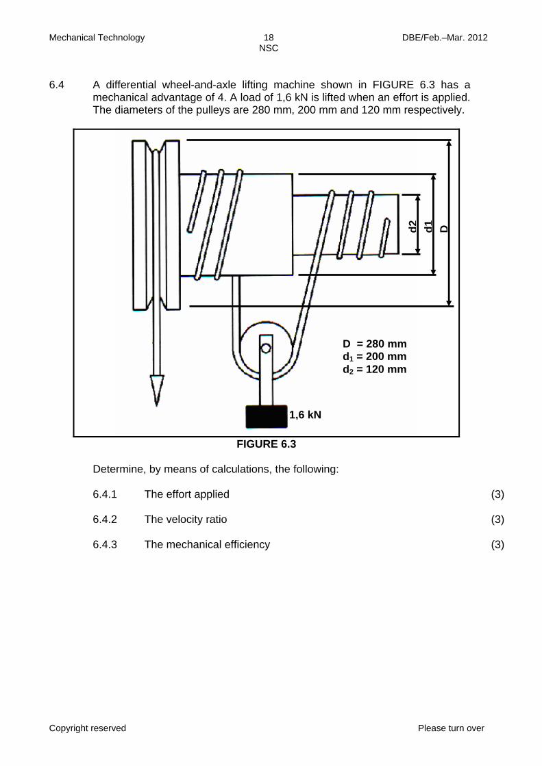
6.4 A differential wheel-and-axle lifting machine shown in FIGURE 6.3 has a
mechanical advantage of 4. A load of 1,6 kN is lifted when an effort is applied. The diameters of the pulleys are 280 mm, 200 mm and 120 mm respectively.
FIGURE 6.3 Determine, by means of calculations, the following: 6.4.1
6.4.2 6.4.3
The effort applied The velocity ratio The mechanical efficiency
(3) (3) (3)
1,6 kN
Dd2 d1
D = 280 mm d1 = 200 mm d2 = 120 mm

Mechanical Technology 19 DBE/Feb.–Mar. 2012 NSC
Copyright reserved
6.5 A single-plate friction clutch is used to transmit power from the engine to the
gearbox main shaft. The plate has an effective diameter of 180 mm. The clutch plate has friction material on both sides with a friction co-efficient of 0,45. The total applied force on the pressure plate is 3,5 kN.
Determine, by means of calculations, the following: 6.5.1
6.5.2
The maximum torque that can be transmitted The power transmitted at 4 500 r/min in kW
(3) (3) [50]
TOTAL: 200
Mechanical Technology 1 DBE/Feb.–Mar. 2012 NSC
Copyright reserved
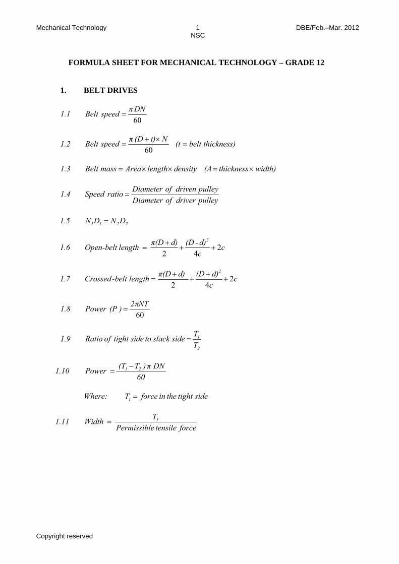
FORMULA SHEET FOR MECHANICAL TECHNOLOGY – GRADE 12
1. BELT DRIVES
1.1 60DNBelt speed π
=
1.2 thickness)belt(tNt) (D πspeedBelt =×+
=60
1.3 width) thickness (A density lengthAreamassBelt ×=××=
1.4
Diameter of driven pulleySpeed ratioDiameter of driver pulley
=
1.5 2211 DNDN =
1.6 ccd)-(Dd)π(D length belt-Open
2
242
+++
=
1.7 ccd)(Dd)π(Dlengthbelt-Crossed
2
242
++
++
=
1.8 60NT2)(PPower π
=
1.9 2
1
TT side slackto sidetight of Ratio =
1.10 60
DN π )T(T Power 21 −=
Where: sidetight the in forceT1 =
1.11 force tensile ePermissibl
T Width 1=
Mechanical Technology 2 DBE/Feb.–Mar. 2012 NSC
Copyright reserved
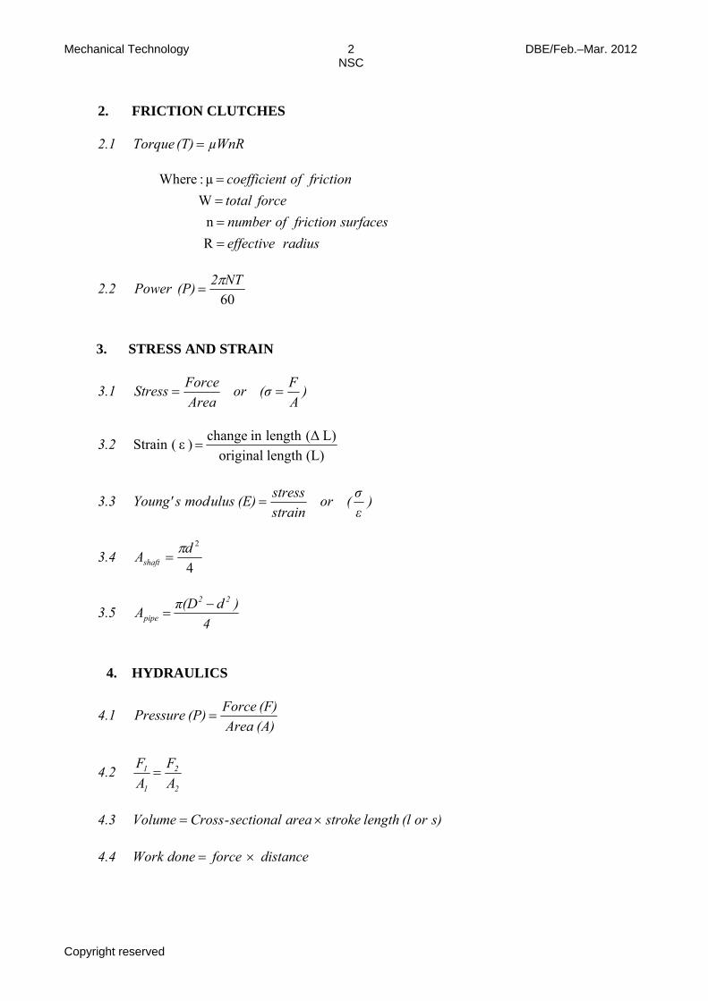
2. FRICTION CLUTCHES 2.1 µWnR(T) Torque =
radiuseffectivesurfacesfrictionofnumber
forcetotalfrictionoftcoefficien
R n W µ:re Whe
====
2.2 60NT2(P)Power π
=
3. STRESS AND STRAIN
3.1 )AF(σor
AreaForceStress ==
3.2 (L)lengthoriginal
L) (Δlengthinchange ) ε (Strain =
3.3 )εσ(or
strainstress(E)ulusmodsYoung' =
3.4 4
2dAshaftπ
=
3.5 4
)dπ(DA22
pipe−
=
4. HYDRAULICS
4.1 (A)Area(F)Force(P)Pressure =
4.2 2
2
1
1
AF
AF
=
4.3 s)or(llengthstrokeareasectional-CrossVolume ×=
4.4 distance forcedone Work ×=
Mechanical Technology 3 DBE/Feb.–Mar. 2012 NSC
Copyright reserved
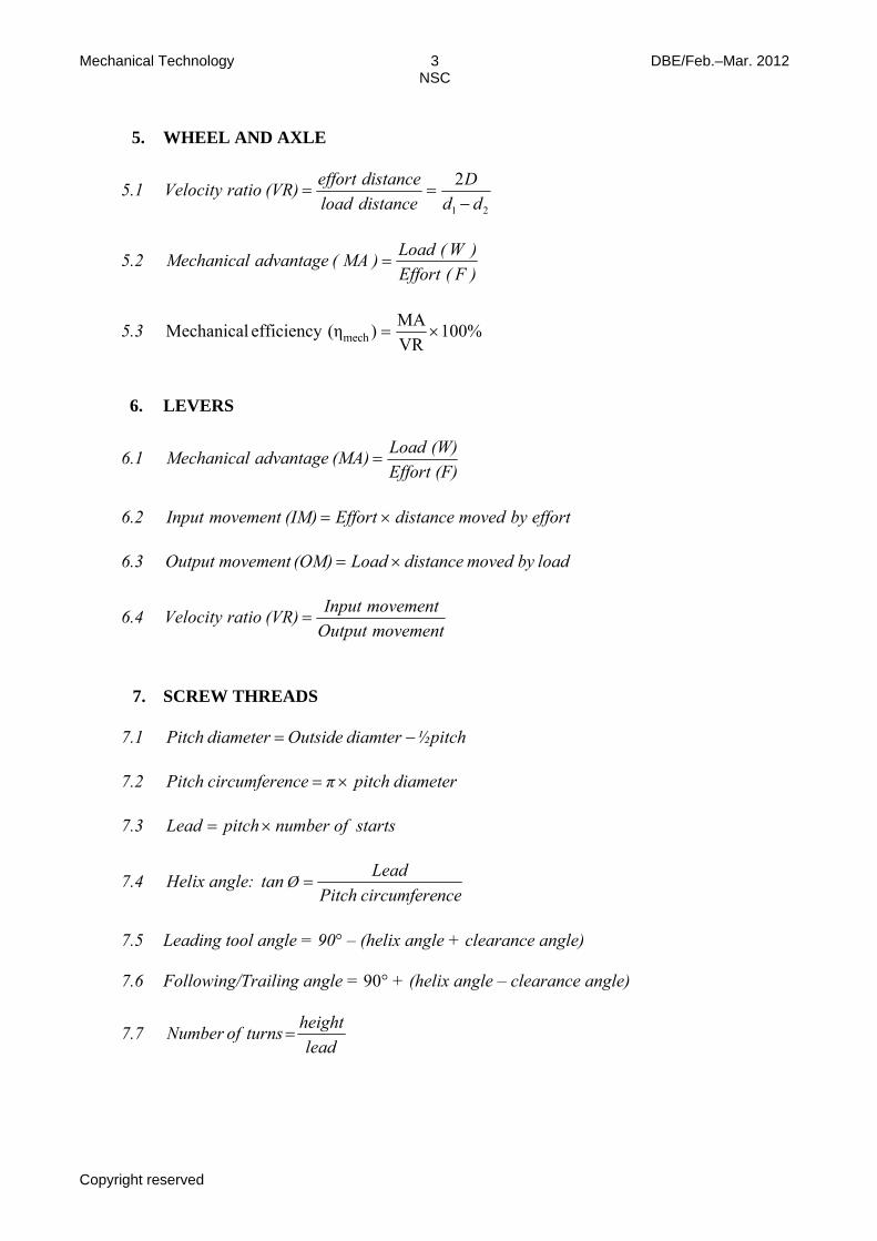
5. WHEEL AND AXLE
5.1 21
2dd
Ddistanceloaddistanceeffort(VR)ratioVelocity
−==
5.2 )F(Effort)W(Load)MA(advantageMechanical =
5.3 100% VRMA)(η efficiency Mechanical mech ×=
6. LEVERS
6.1 (F)Effort(W)Load(MA)advantageMechanical =
6.2 effortbymoveddistanceEffort(IM)movementnputI ×=
6.3 loadby moved distance Load(OM) movement Output ×=
6.4 movementOutput
movementInput(VR)ratioVelocity =
7. SCREW THREADS
7.1 ½pitch diamter Outside diameter Pitch −=
7.2 diameterpitchπncecircumferePitch ×=
7.3 startsofnumberpitchLead ×=
7.4 ncecircumferePitch
Lead tan :angleHelix Ø =
7.5 Leading tool angle = 90° – (helix angle + clearance angle)
7.6 Following/Trailing angle = 90° + (helix angle – clearance angle)
7.7 lead
heightturnsofNumber =
Mechanical Technology 4 DBE/Feb.–Mar. 2012 NSC
Copyright reserved
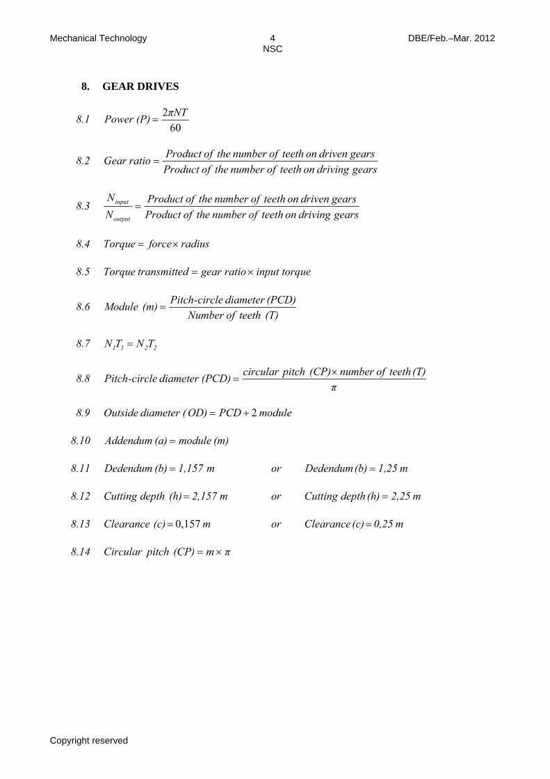
8. GEAR DRIVES
8.1 60
2πNT(P)Power =
8.2 gears driving on teeth of number the of Productgears driven on teeth of number the of Productratio Gear =
8.3 gears driving on teeth of number the of Productgears driven on teeth of number the of Product
NN
output
input =
8.4 radius forceTorque ×=
8.5 torqueinputratiogeardtransmitteTorque ×=
8.6 (T) teeth of Number(PCD) diameter circle-Pitch(m) Module =
8.7 2211 TNTN =
8.8 π
(T) teeth of number (CP) pitch circular(PCD)diameter circle-Pitch ×=
8.9 module PCDD)O(diameter Outside 2+=
8.10 (m)module(a)Addendum =
8.11 m 1,25(b) Dedendum orm1,157(b)Dedendum ==
8.12 m 2,25(h) depth Cutting orm 2,157 (h) depth Cutting ==
8.13 m 0,25 (c) Clearanceorm (c) Clearance == 0,157
8.14 πm(CP)pitchCircular ×=
Mechanical Technology 5 DBE/Feb.–Mar. 2012 NSC
Copyright reserved
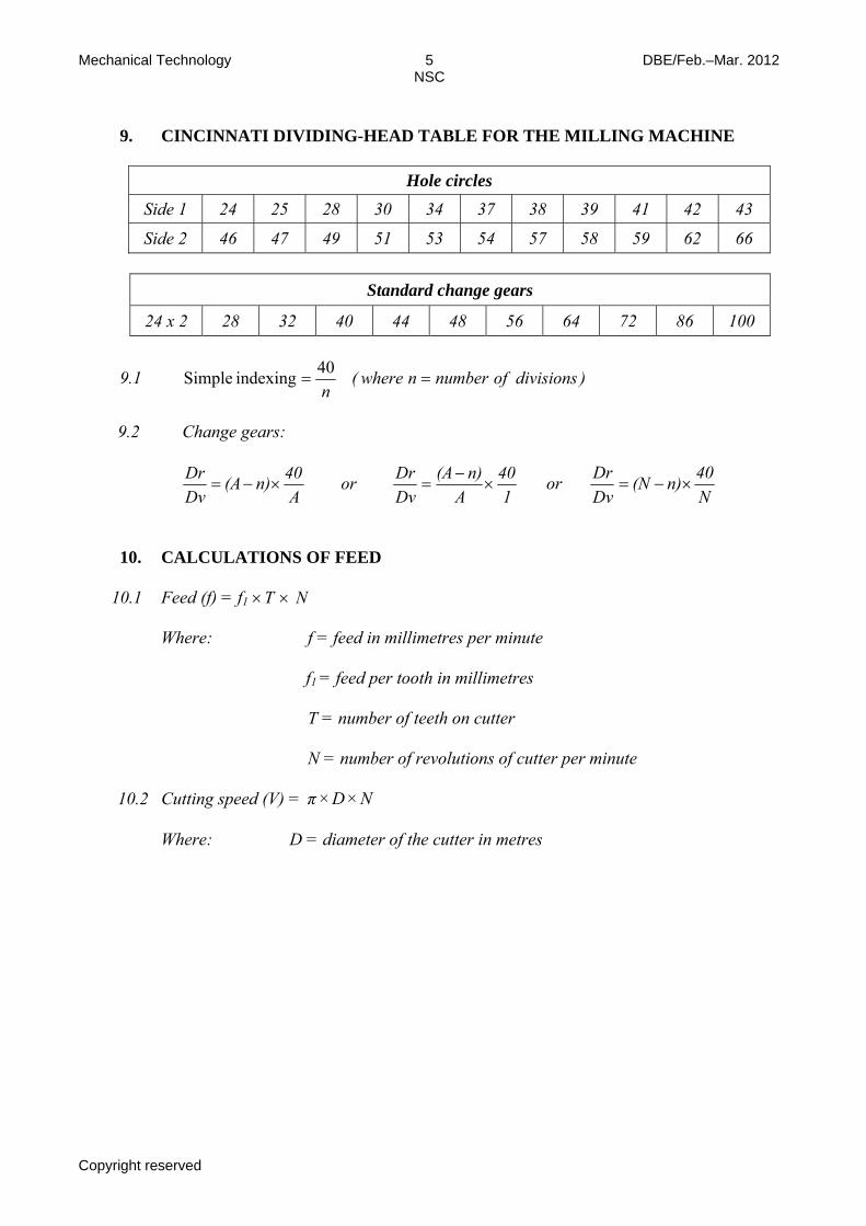
9. CINCINNATI DIVIDING-HEAD TABLE FOR THE MILLING MACHINE
Hole circles Side 1 24 25 28 30 34 37 38 39 41 42 43
Side 2 46 47 49 51 53 54 57 58 59 62 66
Standard change gears
24 x 2 28 32 40 44 48 56 64 72 86 100
9.1 )divisionsofnumbernwhere(n
==40indexing Simple
9.2 Change gears:
1
40A
n)(ADvDror
A40n)(A
DvDr
×−
=×−= or N40n)(N
DvDr
×−=
10. CALCULATIONS OF FEED
10.1 Feed (f) = f1 ×T × N
Where: f = feed in millimetres per minute
f1 = feed per tooth in millimetres T = number of teeth on cutter N = number of revolutions of cutter per minute 10.2 Cutting speed (V) = NDπ ××
Where: D = diameter of the cutter in metres

Mechanical Technology DBE/Feb.–Mar. 2012 NSC
Copyright reserved
ANSWER SHEET CENTRE NUMBER: EXAMINATION NUMBER:
QUESTION 1: MULTIPLE-CHOICE QUESTIONS
1.1 A B C D
1.2 A B C D
1.3 A B C D
1.4 A B C D
1.5 A B C D
1.6 A B C D
1.7 A B C D
1.8 A B C D
1.9 A B C D
1.10 A B C D
1.11 A B C D
1.12 A B C D
1.13 A B C D
1.14 A B C D
1.15 A B C D
1.16 A B C D
1.17 A B C D
1.18 A B C D
1.19 A B C D
1.20 A B C D [20]