Embed Size (px)
Citation preview
STATE OF OHIODEPARTMENT OF TRANSPORTATIONSUPPLEMENTAL SPECIFICATION 840
MECHANICALLY STABILIZED EARTH WALL
January 19, 2007
840.01 Description840.02 Definitions840.03 Materials840.04 Design and Submittal Requirements840.05 Fabrication and Acceptance of Precast Concrete Facing Panels840.06 Construction840.07 On-Site Assistance.840.08 Method of Measurement840.09 Basis of PaymentAppendix A – MSE Wall Acceptance Letter
840.01 Description. This work consists of designing the wall for internal stability, preparing working drawings, and fabricating and constructing a mechanically stabilized earth (MSE) wall using an accredited MSE Wall System. This specification supersedes recommendations by the MSE wall system supplier.
840.02 Definitions. For the purposes of this specification, the following definitions are used:
A. MSE Wall System. A retaining wall system that consists of select granular backfill, reinforcing elements, and facing elements connected to the soil reinforcement.
B. Soil Reinforcement. A material placed within a soil mass to increase the strength of the select granular backfill. Soil reinforcement for MSE walls are typically placed horizontally and consist of steel strips, welded wire mesh, or geogrids (polymer mesh).
C. Facing Panels. The component of an MSE wall that is used to contain the Select Granular Backfill in position at the face of the wall. Facing panels for MSE walls are typically made of precast concrete.
D. Connection Device. The item that connects the soil reinforcement to the facing panel.
E. MSE Wall System Supplier. The Contractor and/or Consultant that designs the MSE wall system for internal stability and in accordance with the plans, designs the components of the MSE wall system and prepares the working drawings.
F. Accredited MSE Wall System. An MSE wall system that has been approved by the Office of Structural Engineering. Each accredited MSE wall system has specific designs for the soil reinforcement, facing panels, and connection devices. The following table lists the accredited MSE wall systems and the associated MSE wall system supplier.

TABLE 840.02-1Accredited MSE wall system MSE wall system supplierReinforced Earth The Reinforced Earth CompanyRetained Earth The Reinforced Earth Company MSE Plus SSL, LLCTricon Retained Soil Tricon PrecastARES Tensar Earth Technologies
Do not use the ARES system for MSE walls that support bridge abutments on spread footings or for MSE walls that have a design height greater than 30 feet. Determine the design height according to 840.04.A, "Design Requirements.".
G. Precaster. A manufacturer certified by the Department according to Supplement 1073 to produce precast concrete products. The Precaster furnishes the facing panels for the Accredited MSE Wall System.
840.03 Materials.A. Precast Concrete Facing Panels. Furnish materials conforming to the following:Portland cement.......................................701.02, 701.04, or 701.05Reinforcing steel....................................................................709.00Microsilica.............................................................................701.10Ground granulated blast furnace slag (GGBFS)....................701.11Fly ash....................................................................................701.13Fine aggregate........................................................................703.02Coarse aggregate....................................................................703.02Air-entraining admixture.......................................................705.10Chemical admixtures............................................................705.12
B. Soil Reinforcement. Furnish soil reinforcements and connection devices conforming to the requirements for the appropriate accredited MSE wall system listed below. Provide certified test data for all of the requirements. Refer to the working drawings for the shape and dimensions of soil reinforcements.
Store soil reinforcements off the ground and protect against weather by covering with tarps. Do not bend steel soil reinforcements after galvanizing.
1. Reinforced EarthFurnish soil reinforcement consisting of steel strips conforming to ASTM A 572,
Grade 65 (ASTM A 572M, Grade 450) and galvanized according to the requirements of ASTM A 123 (ASTM A 123M). Furnish connection devices consisting of tie strips conforming to ASTM A 1011, Grade 50 (ASTM A 1011M, Grade 340) and galvanized according to the requirements of ASTM A 123 (ASTM A 123M). Furnish bolts and nuts conforming to ASTM A 325 (ASTM A 325M) and galvanized according to the requirements of ASTM A 153 (ASTM A 153M).
2. Retained EarthFurnish soil reinforcement consisting of welded wire mesh conforming to ASTM A 185
(ASTM A 185M) and galvanized according to the requirements of ASTM A 123 (ASTM
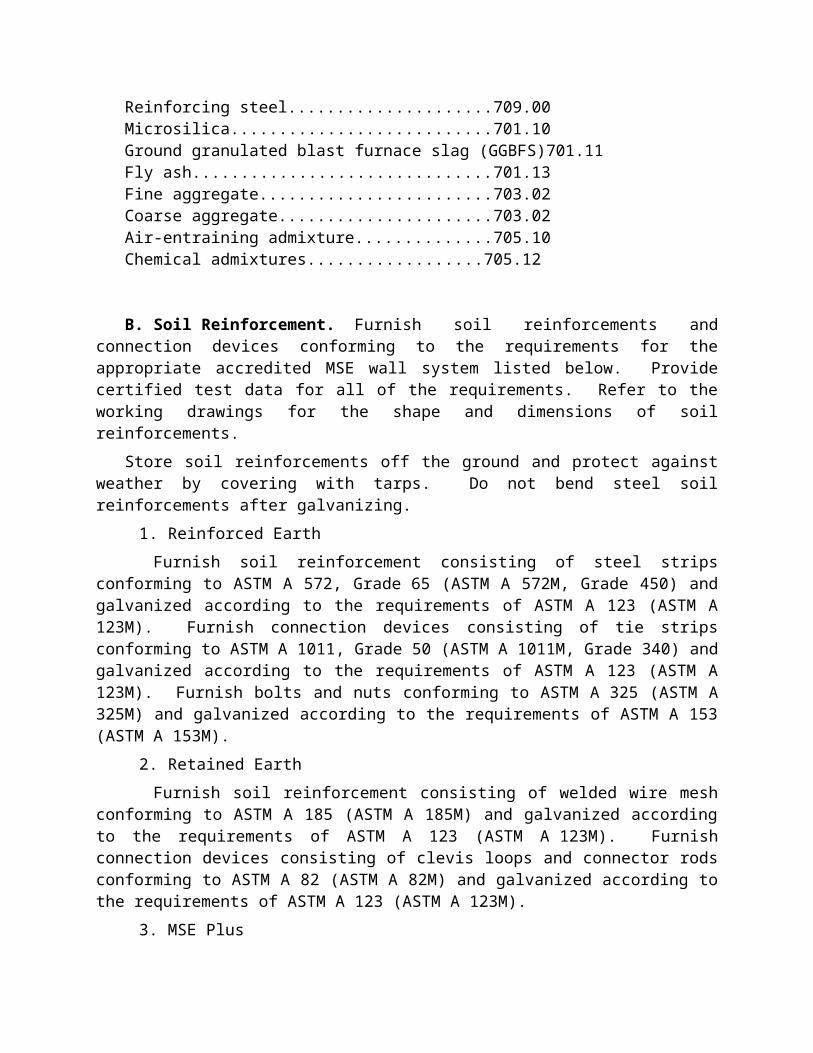
A 123M). Furnish connection devices consisting of clevis loops and connector rods conforming to ASTM A 82 (ASTM A 82M) and galvanized according to the requirements of ASTM A 123 (ASTM A 123M).
3. MSE PlusFurnish soil reinforcement consisting of welded wire mesh conforming to ASTM A 185
(ASTM A 185M) and galvanized according to the requirements of ASTM A 123 (ASTM A 123M). Furnish connection devices consisting of loop embeds and connecting pins conforming to ASTM A 82 (ASTM A 82M) and galvanized according to the requirements of ASTM A 123 (ASTM A 123M).
4. Tricon Retained SoilFurnish soil reinforcement consisting of welded wire mesh conforming to ASTM A 185
(ASTM A 185M) and galvanized according to the requirements of ASTM A 123 (ASTM A 123M). Furnish connection devices consisting of panel anchors and locking rods conforming to ASTM A 82 (ASTM A 82M) and galvanized according to the requirements of ASTM A 123 (ASTM A 123M).
5. ARESFurnish soil reinforcement consisting of high density polyethylene (HDPE) geogrids
and connection devices consisting of HDPE geogrids and bodkin bars. Furnish either UX1400MSE, UX1500MSE UX1600MSE or UX1700MSE geogrids from Tensar Earth Technologies, that conform to the following requirements.
TABLE 840.03-1UX1400MSE UX1500MSE UX1600MSE UX1700MSE
Minimum Tensile StrengthASTM D 6637
4,800 lb/ft(70 kN/m)
7,810 lb/ft(114 kN/m)
9,870 lb/ft(144 kN/m)
11,990 lb/ft(175 kN/m)
C. Bearing Pads. Furnish bearing pads that will provide a long term horizontal joint spacing of at least 3/8 inches (10 mm). Provide bearing pads to the dimensions shown in the working drawings.
D. Facing Panel Joint Cover. Furnish a woven, 100% monofilament, geotextile fabric conforming to AASHTO M 288 Table 1, Class 2 less than 50% elongation; with a UV stability according to ASTM D4355 of 90% after 500 hours, and conforming to AASHTO M 288 Table 2 requirements for less than 15% in situ soil passing 0.075 mm sieve. Provide certified test data for the geotextile fabric.
Use an adhesive that secures the fabric to the wall during construction. Use a minimum geotextile fabric width of 24 inches (610 mm). Before installation, protect the geotextile fabric from exposure to direct sunlight.
E. Select Granular Backfill. Furnish Select Granular Backfill (SGB) material in the reinforced soil zone and other locations shown in the plans conforming to Item 304 or 703.11 Structural Backfill Type 2; and the following requirements:
1. Do not use slag materials or recycled portland cement concrete.

2. Ensure that the material has an internal angle of friction equal to or greater than 34 degrees when tested by AASHTO T 236, except as follows: a. Test the material passing a number 10 sieve.
(1) Determine the maximum dry density and optimum moisture of the minus 10 material according to AASHTO T-99 Method A.
(2) Remold the sample at optimum moisture and 98% of the maximum dry density.
(3) Perform the test three times at normal stresses of 10, 20, and 40 pounds per square inch.
(4) Plot the maximum shear stress versus the normal stress for each test. Draw a straight line that is a best fit to the three points using the least-squares method. Determine the internal angle of friction by measuring the angle of the best fit line from horizontal.
(5) If the SGB has material retained on the number 10 sieve and the shear strength is less than 34 degrees, then the Contractor may submit an alternate shear test to perform on the SGB.
3. For MSE wall systems that use steel soil reinforcements and connection devices, ensure that the material meets the following requirements:a. A pH between 5.0 and 10.0 when tested according to AASHTO T 289 b. A resistivity greater than 3000 ohm-cm when tested according to AASHTO T
288. If the material has a resistivity greater than 5000 ohm-cm, the Department will waive testing for chloride and sulfate levels.
c. A chloride level less than 100 ppm when tested according to AASHTO T 291.d. A sulfate level less than 200 ppm when tested according to AASHTO T 290.
4. For MSE wall systems that use geogrid soil reinforcement, ensure that the material meets the following requirements:a. A pH between 4.5 and 9.0 when tested according to AASHTO T 289
Obtain all acceptance samples from the actual material stockpile. Thirty days before the MSE wall construction, provide certified test data from an
independent testing laboratory that verifies the material meets all requirements. The Engineer will conditionally accept the material based upon a visual inspection of the material and a review of the certified test data. Final acceptance of material will be based on testing of quality assurance samples by the Department to verify that the certified test data is accurate. The Engineer will sample the material when the material is delivered to the project and provide the sample and the certified test data to the Office of Materials Management.
F. Backfill Drainage Material. Furnish materials conforming to:Plastic Pipe.............................................................................707.33Filter Fabric, Type A............................................................712.09

Furnish porous backfill consisting of gravel or stone with a No. 57 size gradation according to Table 703.01-1 in the locations where perforated pipe is used. Use material with a sodium sulfate soundness loss less than 15 percent (5 cycle) when tested according to AASHTO T 104.
Furnish natural sand, gravel or sand manufactured from stone complying with 703.02.A, 703.03 or 703.05.A fine aggregate in locations where the non-perforated pipe is used.
If the drainage pipe is installed within the select granular backfill, the Contractor may furnish a pipe manufactured with filter fabric surrounding and attached to the pipe, in lieu of porous backfill. Ensure that the pipe and filter fabric meet the above requirements.
G. Foundation Preparation.1. Geotextile Fabric. Furnish a woven, 100% monofilament, geotextile fabric
conforming to AASHTO M 288 Table 1, Class 2 less than 50% elongation; conforming to AASHTO M 288 Table 2 requirements for less than 15% in situ soil passing 0.075 mm sieve. Provide certified test data for the geotextile fabric.
2. Furnish crushed carbonate stone, gravel, durable sandstone, durable siltstone, or granulated slag conforming to 703.16.C Granular Material Type C.
H. Concrete Coping. Furnish materials conforming to:Concrete, Class C........................................................................511Epoxy coated reinforcing steel..............................................709.00Preformed expansion joint filler............................................705.03
I. Leveling Pad. Furnish Class C Concrete according to Item 511.J. Concrete Sealer. Furnish epoxy-urethane sealer conforming to 705.23.A.K. Pile Sleeves. Furnish corrugated polyethylene smooth lined pipe, 707.33, or PVC
corrugated smooth interior pipe, 707.42. Furnish sleeves with a diameter at least 6 inches (150 mm) greater than the largest pile’s diagonal dimension.
L. Natural Soil. Furnish A-4-A, A-6 or A-7-6 natural soil meeting the requirements of 203.02.I.
840.04 Design and Submittal Requirements.A. Design Requirements. Design the MSE wall conforming to Section 5.8 of the
AASHTO Standard Specifications for Highway Bridges, 17 th edition, 2002, and the requirements listed below. In the event of a conflict, this specification will govern.
1. Only use an accredited MSE wall system. 2. For design purposes, measure the wall height from the top of the leveling pad to the top
of the coping. When the wall retains a sloping backfill, the wall’s design height (h) will conform to AASHTO Figure 5.8.2B. If the wall will be located at an abutment measure the wall height from the top of the leveling pad to the profile grade elevation at the face of the wall.
3. Use the following soil parameters in the design. These parameters are not to be used for material acceptance.
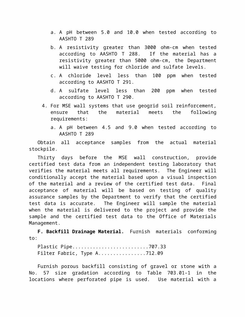
TABLE 840.04-1Fill Zone Type of Soil Design Soil
Unit WeightFriction
AngleCohesion
Reinforced Soil Select Granular Backfill 120 lbs/ft3
(18.9 kN/m3)34o 0
Retained Soil(Soil behind the Reinforced
Soil Zone)
On-site soil varying from sandy lean clay to silty sand
120 lbs/ft3
(18.9 kN/m3)30o 0
4. Use the Simplified Coherent Gravity Method conforming to AASHTO 5.8.4.1 for internal stability calculations.
5. Include a live load surcharge when applicable, even if there is an approach slab at the bridge abutment.
6. Assume a water level within the reinforced soil at the invert elevation of the drainage pipe.
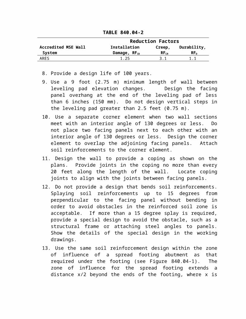
7. Use the following reduction factor values for geogrid soil reinforcementTABLE 840.04-2
Reduction FactorsAccredited MSE Wall System Installation Damage, RFID Creep, RFCR Durability, RFD
ARES 1.25 3.1 1.1
8. Provide a design life of 100 years. 9. Use a 9 foot (2.75 m) minimum length of wall between leveling pad elevation changes.
Design the facing panel overhang at the end of the leveling pad of less than 6 inches (150 mm). Do not design vertical steps in the leveling pad greater than 2.5 feet (0.75 m).
10. Use a separate corner element when two wall sections meet with an interior angle of 130 degrees or less. Do not place two facing panels next to each other with an interior angle of 130 degrees or less. Design the corner element to overlap the adjoining facing panels. Attach soil reinforcements to the corner element.
11. Design the wall to provide a coping as shown on the plans. Provide joints in the coping no more than every 20 feet along the length of the wall. Locate coping joints to align with the joints between facing panels.
12. Do not provide a design that bends soil reinforcements. Splaying soil reinforcements up to 15 degrees from perpendicular to the facing panel without bending in order to avoid obstacles in the reinforced soil zone is acceptable. If more than a 15 degree splay is required, provide a special design to avoid the obstacle, such as a structural frame or attaching steel angles to panels. Show the details of the special design in the working drawings.
13. Use the same soil reinforcement design within the zone of influence of a spread footing abutment as that required under the footing (see Figure 840.04-1). The zone of influence for the spread footing extends a distance x/2 beyond the ends of the footing, where x is the distance between the bottom of the footing and the top of the leveling pad.

Figure 840.04-1 Zone of Influence
B. Submittal of Working Drawings and Calculations. Prepare design calculations according to the above requirements. Prepare working drawings and include at least the following information in the working drawings:
1. A site plan for the full length of the retaining wall that shows:a. Station and offset at the face of the wall measured from the centerline of
construction for the ends of the wall and any changes in wall alignment, obtained from the contract documents.
b. Horizontal and vertical curve data for curved walls as outlined and shown on the contract documents.
c. Limits of soil reinforcement.d. All obstructions to the soil reinforcement, such as piling or catch basins.
2. An elevation view for the full length of the retaining wall that shows:a. Location of each individually labeled facing panel.b. Elevations at the ends of the wall and any changes in elevation at the top or
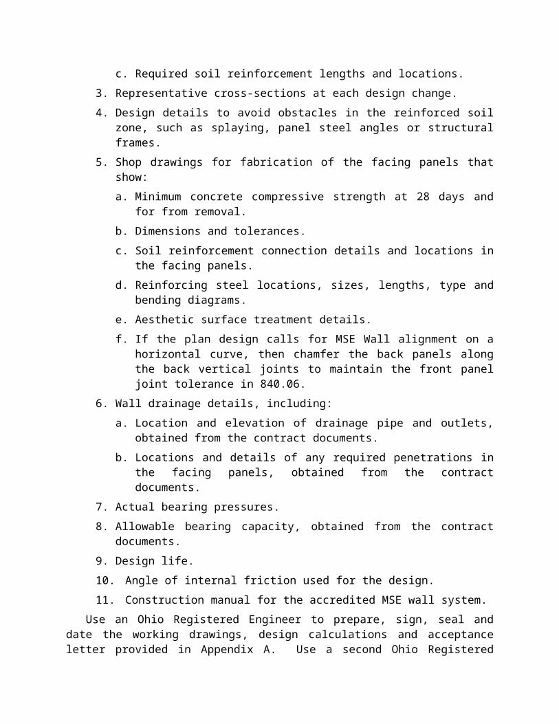
bottom of the wall.c. Required soil reinforcement lengths and locations.
3. Representative cross-sections at each design change.4. Design details to avoid obstacles in the reinforced soil zone, such as splaying, panel
steel angles or structural frames. 5. Shop drawings for fabrication of the facing panels that show:
a. Minimum concrete compressive strength at 28 days and for from removal.b. Dimensions and tolerances.c. Soil reinforcement connection details and locations in the facing panels. d. Reinforcing steel locations, sizes, lengths, type and bending diagrams.

e. Aesthetic surface treatment details.f. If the plan design calls for MSE Wall alignment on a horizontal curve, then
chamfer the back panels along the back vertical joints to maintain the front panel joint tolerance in 840.06.
6. Wall drainage details, including:a. Location and elevation of drainage pipe and outlets, obtained from the contract
documents.b. Locations and details of any required penetrations in the facing panels, obtained
from the contract documents.7. Actual bearing pressures.8. Allowable bearing capacity, obtained from the contract documents.9. Design life.10. Angle of internal friction used for the design.11. Construction manual for the accredited MSE wall system.
Use an Ohio Registered Engineer to prepare, sign, seal and date the working drawings, design calculations and acceptance letter provided in Appendix A. Use a second Ohio Registered Engineer to check, sign, seal and date the working drawings, design calculations and acceptance letter provided in Appendix A.
Submit four copies of the working drawings, design calculations and acceptance letter to the Engineer at least 30 days before any part of wall construction begins. Submit drawings on 1117 inch paper, and calculations on 8½11 inch paper. Also submit drawings and calculations in electronic format in tiff format. The Engineer will submit the drawings, calculations and acceptance letter to the Office of Structural Engineering for review. The review will be completed within 21 days.
Ensure all submittals meet the requirements for materials, design, and construction. Ensure all required field measurements are made and included in the drawings. Coordinate all details of the work to be performed by other entities on the project. The Department will not make allowance for additional cost or delays to the Contractor for incorrect fabrication as a result of failure to perform this coordination.
Department acceptance of the submittal does not relieve the Contractor or the MSE wall system supplier from responsibility for errors and omissions found after acceptance of the submittal.
840.05 Fabrication and Acceptance of Precast Concrete Facing Panels. Provide precast concrete facing panels from a precast concrete producer certified under Supplement 1073.
A. Producer Notification. Notify the Engineer of the certified precaster before the MSE preconstruction meeting. Do not start facing panel fabrication until the working drawings and design calculations have been accepted by the Department.
B. Concrete Proportioning. Proportion a concrete mix design that provides the minimum compressive strength required in the working drawings and the minimum over design of ACI 318 and conforms to the air content requirements of Supplement 1073.
C. Form Inspection. Before casting, measure all forms for tolerances defined in 840.05 H and document the measurements. Reject any forms not within tolerances.
D. Casting. Before casting, place the reinforcing steel, soil reinforcement connection devices, and lifting elements at the locations shown on the working drawings and to the tolerances specified below. Design the lifting elements to eliminate concrete spalling during handling. Cast the panels on a flat area, with the front face down. Use clear form oil approved by the MSE wall system supplier and do not substitute the form oil after the casting operation begins.
Leave all forms in place until the concrete panel can be removed without damage. Use the working drawings to define the minimum compressive strength required for form removal. Test and record the strength of the concrete before removing the forms.
E. Curing. Use the curing method recommended by the MSE wall system supplier. Cure the concrete sufficiently to develop the minimum compressive strength required in the working drawings.
F. Concrete Testing. During facing panel production, randomly sample the concrete and test according to ASTM C 172 and Supplement 1073. A single compressive strength sample consists of at least four test cylinders for each production lot. A production lot is either 40 panels or a single day’s production, whichever is less. Perform compressive strength testing according to the requirements of Supplement 1073.
G. Concrete Finish and Aesthetic Treatment. If an aesthetic surface treatment is shown in the plans or working drawings, cast it into the front face of the panels. If an aesthetic surface treatment is not required, finish the front face of the panels to a smooth surface. Finish the back face of the panels to a uniform surface, free of open pockets of aggregate. Ensure that both faces conform to the tolerances specified below.
H. Panel Dimensions and Tolerances. Fabricate the panels with a minimum thickness of 5 ½” (140mm) and a maximum panel dimension of 5 x 5 feet (1.52 x 1.52m). The minimum thickness does not include the aesthetic surface treatments. Use the tolerances in Table 840.05-1.
TABLE 840.05-1Tolerance
Panel dimensions ± 1/8 in. (3 mm)Panel squareness (difference between the two diagonals) ± 1/4 in. (6 mm)Panel thickness ± 1/8 in. (6 mm)Location of soil reinforcement connection device ± 1/4 in. (6 mm)Panel surface (size of surface defect measured over a length of 5 ft (1.5 m))
Smooth formed finishTextured finish
± 1/8 in. (3 mm)± 5/16 in. (8 mm)
Position of reinforcing steel ± 1/8 in. (3 mm)
Inspect and document that the panels are dimensionally correct; that the soil reinforcement connection devices are at the locations shown on the working drawings; that the panel finishes

are correct; that concrete’s form removal and final strength meet working drawings; and that all tolerances have been met.
I. Precast Panel Rejection, at the plant and field site. Reject panels having any of the following:
1. Defects that indicate imperfect molding.2. Defects that indicate honeycombed or open texture concrete.3. Defects in the physical characteristics of the concrete, or damage to the aesthetic surface
treatments.4. Concrete chips or spalls that exceed 4 inches (100 mm) wide or 2 inches (50 mm)
deep. a. Repair all chips and spalls of any dimension.
5. Stained form faces, due to form oil, curing or other contaminants.6. Signs of aggregate segregation.7. Cracks wider than 0.01 inches (0.25 mm) or penetrating more than an inch or longer
than 12 inches (300 mm). 8. Face panels that do not meet the specified tolerances.9. Soil reinforcement or connection devices that are damaged.
a. Connections bent more than 15 degrees are not repairable.10. Lifting inserts that are not useable.11. Exposed reinforcing steel.12. Insufficient concrete compressive strength
J. Panel Markings. Permanently mark the back surface of each panel with the date of manufacture, the panel identification from the working drawings, the production lot number, and the precaster’s inspection and acceptance mark. The precaster’s marks represent that the panel meets all specification requirements.
The precaster shall maintain record fabrication drawings according to Supplement 1073 and this specification for each panel design produced.
K. Handling, Storing and Shipping Panels. Handle, store, and ship panels to avoid chipping, cracking and fracturing the panels; excessive bending stresses; and damaging the soil reinforcement connection devices. Support panels on firm blocking while storing and shipping.
Do not ship panels until concrete has attained the required compressive strength.Submit 840.05.I shipment documentation to the Engineer as the facing panels are delivered
to the project along with the TE-24 shipping document.840.06 Construction.
A. MSE Wall Preconstruction Meeting. Request a meeting at least 15 days before wall construction begins and after the Department has accepted the working drawings and design calculations. Have a representative from the accredited MSE wall system supplier attend the meeting. Provide a complete written sequence of construction at the meeting and review the
sequence, any construction issues, the specifications and the accredited MSE wall system requirements. Determine any issues that need to be resolved for construction. Resolve those issues.
During the MSE wall preconstruction meeting, request sampling of the Select Granular Backfill for verification acceptance.
B. Facing Panel Inspection. Inspect all facing panels for any damage and reject panels that do not conform to 840.05.J. Provide acceptable replacement panels for any panels rejected. Either replace panels or document the damage and propose to the Engineer a complete repair method for the damaged panel.
C. Wall Excavation. Excavate to the limits shown in the plans. Remove unsuitable foundation soils to the limits shown in the plans. Develop and implement a plan to protect the open excavation from surface drainage during construction and until the wall is placed.
D. Foundation Preparation. For a width at least 1 foot (0.3 m) greater than the width of the reinforced soil zone, level and compact the foundation soil according to Item 203. The Department will perform the compaction tests for the foundation according to Supplement 1015. Notify the Engineer if the foundation does not meet the compaction requirements.
Once the foundation has been compacted, the Department will review the foundation to verify the allowable bearing capacity shown in the plan.
After the foundation has been compacted and accepted, place the geotextile fabric on the foundation soil according to 204.07. Place 12 inches (300 mm) of granular material type C on top of the geotextile fabric. Spread and compact the granular material type C to meet the requirements of 203.06 and 203.07. Compact the granular material type C to a minimum of 98 percent of the test section maximum. The Department will perform the compaction tests according to Supplement 1015.
E. Leveling Pad Construction. Construct the concrete leveling pad using unreinforced, cast-in-place concrete. Do not use precast leveling pads. The leveling pad shall be 6 inches (150 mm) thick and 24 inches (610 mm) wide. Cure the concrete and do not start wall erection until specimen beams have attained a modulus of rupture of 400 pounds per square inch (4.2 MPa).
Construct all leveling pads so the top of the pad is within 1/8 inch (3 mm) of the elevation shown on the working drawings. Construct the pads so that the surface does not vary more than 1/8 inch in 10 feet (3 mm in 3 m). Check the leveling pad construction before wall erection and report the elevations and surface variation to the Engineer.
If the design calls for a change in the leveling pad elevation (i.e. steps), then construct the leveling pad so that the facing panel extends no more than 6 inches (150 mm) beyond the end of the leveling pad.
F. Wall Drainage. Install drainage as shown on the plans. Use perforated pipe within the wall limits and non-perforated pipe outside the wall limits. Provide banded or sealed joints. Slope the drainage pipe to provide positive drainage. Place the fine aggregate backfill according to 603.11. Compact the fine aggregate according to 603.11.C. Place and compact the No. 57’s according to 603.11.D. Place filter fabric between the No. 57’s and the fine aggregate to prevent piping. Completely wrap the No. 57’s with filter fabric. Use a one foot (0.3m) overlap for the filter fabric. If it is not possible to outlet the drainage pipe, then notify the Engineer.

If it rains or water collects in the excavation at any time, pump the water out of the excavation immediately.
G. Wall Erection. Place facing panels in the sequence shown on the working drawings. Lift panels using the lifting devices set into the upper edge of each panel. Place the initial row of panels on the centerline of the leveling pad and level the panel. Use shims to level the panels. If shim height is greater than 3/8 inches (10 mm) start the erection over. Do not use bearing pads to level the panels. Do not install panels that overhang the leveling pad transversely. Reconstruct the leveling pad if the panels are transversely overhanging.
Facing panels are allowed to extend beyond the end of the leveling pad up to 6 inches (150 mm) when the leveling pad changes elevation. Fill the void with Select Granular Backfill immediately after the first row of panels are set, wedged, braced and clamped.
Starting with the second row of panels, install at least two bearing pads per panel, uniformly spaced, to properly construct the panels’ horizontal joint. After each panel has been placed, ensure that the panel is horizontally level.
Construct the panels so that the horizontal and vertical joints are ½ to 1-inch (13 to 25 mm) wide. Use ¾-inch (19 mm) spacers to control the joint spacing. Once this joint spacing is achieved, record the joint gap on the working drawings and present this information to the Engineer once a week. If the required joint spacing is not achieved, make the required corrective action.
The Engineer will hold a flashlight perpendicular to the facing panel to determine if the fabric is exposed. If the fabric is exposed then the joint is unacceptable. Submit a repair method to the Department for protecting the fabric.
Initially, batter the panels back an appropriate amount so that the final vertical position is achieved.
Use external bracing as necessary to stabilize and batter the first panel lift and any other panel lifts that require external stability. Place panels and backfill in successive horizontal lifts according to the sequence shown on the working drawings.
Once the panels have been erected and the Select Granular Backfill placed to a height matching the outside proposed ground elevation, fill the outside embankment immediately. Use the requirements of Item 203 for this work. If water has ponded in front of the wall then pump the water out prior to constructing the embankment.
Maintain the panels in their vertical and battered position by means of temporary wood wedges and clamps placed at the panel joints. Check vertical tolerances with a 6-foot (2 m) level. Check the panel to panel horizontal tolerance with a 6-foot (2 m) straightedge. Do not release the panel from the lifting device until the position of the panel has been checked and the wedges and clamps are in place.
After compacting the backfill behind each row of panels, check the horizontal and vertical alignment of the wall and make the adjustments as required. Remove the clamps and wedges prior to placing the next row of panels and after the vertical and horizontal alignment is checked.
Do not exceed the wall’s vertical and horizontal alignment tolerances of 1/2 inch (13 mm) when measured along a 10-foot (3 m) straight edge. Do not exceed 1/2 inch (13mm) from horizontal and vertical alignment at any point along the 10-foot (3 m) straight edge. Do not
construct any panel more than 1/2 inch (13 mm) out of vertical or horizontal alignment from the adjacent panels. Do not exceed the final overall vertical tolerance of the wall (plumbness from top to bottom) of a ½ inch (13 mm) per 10 feet (3 m) of wall height. Starting with the third row of panels, use a plumb bob to check the overall vertical tolerances for every panel. Continuously monitor the batter, alignment and tolerances. Make adjustments as required.
Do not pull on the soil reinforcement to align the panels. Remove the wedges as soon as the second panel above the wedged panel is completely
erected and backfilled.Install the geotextile fabric strip over each horizontal and vertical panel joint. Center the
fabric over the joint. Use a minimum 12-inch (300 mm) lap between cut sections of the fabric. Clean the concrete to remove dirt by using a brush before applying the adhesive and fabric. Place the fabric so that it covers the horizontal and vertical joints by 12 inches (300 mm) on each side of the joint. Attach the fabric to the back of the facing panel using an adhesive that securely bonds the fabric to the facing panel. Apply adhesive to the wall or the fabric for the full perimeter of the installed length and width of the geotextile strip. Use the adhesive manufacturer’s temperature recommendations.
When the fabric is placed around a slip joint, allow some horizontal slack in the fabric to allow for movement.
H. Soil Reinforcement Installation. Place the soil reinforcement perpendicular to the facing panel unless otherwise shown on the working drawings. If steel soil reinforcement cannot be placed perpendicular to the wall, it may be splayed up to 15 degrees. The transverse wires of welded wire mesh may be cut in order to splay the soil reinforcement. If more than a 15 degree splay is required to place the soil reinforcement, then a special design is required on the working drawings. If a situation is encountered in the field that was not accounted for on the working drawings, notify the Engineer.
If bolts are used to connect the soil reinforcement to the facing panel, place the bolts in the connection from the bottom and attach the washer and nut. Tighten the bolt with a wrench or socket.
If loops and a pin are used to connect the soil reinforcement to the facing panel, place the pin through all of the loops. Place wooden wedges between the pin and the panel to remove any slack in the connection. Ensure the pin and loops are in contact with each other.
Before placing Select Granular Backfill over the soil reinforcements ensure that 1. The soil reinforcement matches what is shown on the working drawings.2. The soil reinforcement is continuous from the panel to the end of the reinforced soil
zone.3. The soil reinforcement is connected to the panel correctly. Replace the panel if
necessary to correctly connect the soil reinforcement. 4. For geosynthetic reinforcements ensure that the soil reinforcement is pulled taut to
eliminate wrinkles or folds and held in place during placement of the select granular backfill.
Do not cut or splice steel soil reinforcements. Do not operate equipment directly on the soil reinforcements.

I. Select Granular Backfill Placement. Transport and handle the Select Granular Backfill (SGB) in a manner that minimizes the segregation of the material.
Use SGB Item 304 material, in 840.03.E, for a height of at least 3 feet (1.0 m) above the bottom of the leveling pad elevation. Use SGB Item 304 or Item 703.11, in 840.03.E, in other areas of select granular backfill.
Place the SGB after each row of facing panels is erected. Place the SGB in maximum 8 inch (200 mm) loose lifts.
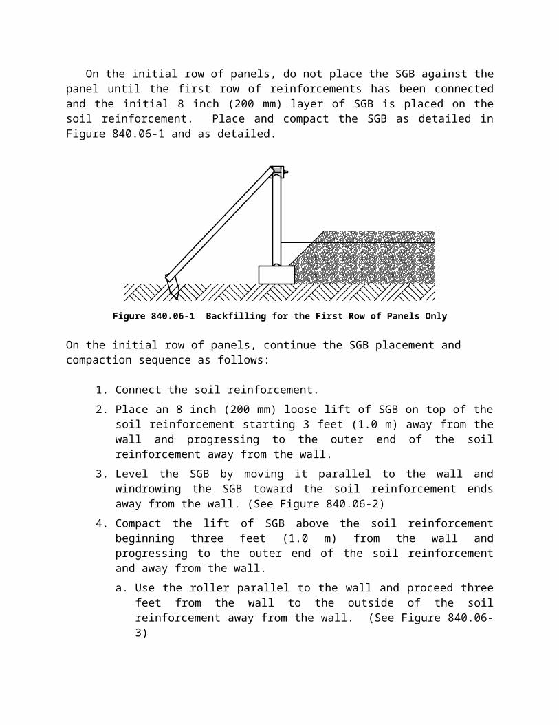
On the initial row of panels, do not place the SGB against the panel until the first row of reinforcements has been connected and the initial 8 inch (200 mm) layer of SGB is placed on the soil reinforcement. Place and compact the SGB as detailed in Figure 840.06-1 and as detailed.
Figure 840.06-1 Backfilling for the First Row of Panels Only
On the initial row of panels, continue the SGB placement and compaction sequence as follows:
1. Connect the soil reinforcement.2. Place an 8 inch (200 mm) loose lift of SGB on top of the soil reinforcement starting 3
feet (1.0 m) away from the wall and progressing to the outer end of the soil reinforcement away from the wall.
3. Level the SGB by moving it parallel to the wall and windrowing the SGB toward the soil reinforcement ends away from the wall. (See Figure 840.06-2)
4. Compact the lift of SGB above the soil reinforcement beginning three feet (1.0 m) from the wall and progressing to the outer end of the soil reinforcement and away from the wall. a. Use the roller parallel to the wall and proceed three feet from the wall to the
outside of the soil reinforcement away from the wall. (See Figure 840.06-3)5. Place and compact the SGB in the void below the reinforcement next to the wall in 8
inch (200 mm) loose lifts up to the level of the reinforcement. a. The Contractor may elect to flood this material instead of compacting.
(1) If flooding is elected use the following:

(a) Construct a 6-inch (150 mm) high wall surrounding the lift to be flooded. The wall may be the MSE wall or SGB. The walls are to hold the water before the water dissipates through each loose lift.
(b) Pond 4 inches (100 mm) of water on each 8-inch (200 mm) loose lift.(c) Allow the water to dissipate and for the lift to stabilize (so the next layer
may be constructed) before placing the next lift. If the water does not readily dissipate or the material remains unstable then use the compaction method.
(d) Provide drainage through the use of drainage ditches, pumps, or other equipment.
6. Place the 8 inch (200 mm) lift of SGB in the void left above the reinforcing strip between the wall and the material 3 feet away from the wall. (See Figure 840.06-4)
7. Compact the SGB three feet (1.0 m) from the wall. (See Figure 840.06-5)
Figure 840.06-2 Initial Material Lift Placement (Plan View)
Figure 840.06-3 Initial Compaction (Plan View)
Figure 840.06-4 Material Placement within 3 feet from the Wall (Plan View)
Figure 840.06-5 Final Compaction Operation Next to the Wall
Use the following sequence for SGB placement after the initial row of panels. Place and compact the next layers of SGB up to a compacted level of 2 inches (50 mm) higher than the soil reinforcement connection device on the facing panel before installing the soil reinforcements. After placing the soil reinforcement use the following sequence:
1. Place an 8 inch (200 mm) loose lift of SGB 3 feet (1.0 m) away from the wall and progressing to the outer end of the soil reinforcement away from the wall.a. Level the SGB by moving it parallel to the wall and windrowing the SGB toward
the soil reinforcement ends away from the wall. (See Figure 840.06-2) 2. Compact the lift of SGB beginning three feet from the wall and progressing to the
outer end of the reinforcement and away from the wall. a. Use the roller parallel to the wall and proceed three feet (1.0 m) from the wall to
the outside of the soil reinforcement away from the wall. (See Figure 840.06-3) 3. Place an 8 inch (200 mm) lift of SGB in the void left between the wall and the material
3 feet (1.0 m) away from the wall. (See Figure 840.06-4 )4. Compact the SGB three feet (1.0 m) from the wall. (See Figure 840.06-5) 5. Continue this sequence until the SGB and soil reinforcements are complete.
Compact and test the Select Granular Backfill according to Item 203 except as follows: 1. Place the Select Granular Backfill in loose lifts not exceeding 8 inches (200 mm).
Monitor and record all Select Granular Backfill placement using form CA-EW-12.2. Compact using a vibratory roller with a static weight between 6 to 10 tons (7 and 11
metric tons). Operate compaction equipment in a direction parallel to the wall facing.3. Test the compaction using Supplement 1015. Use either Test Section Method A or B
according to Supplement 1015 and 203.07.

4. Sample the Select Granular Backfill material and create a moisture density curve according to AASHTO T 99 Method C for each type and source of material.
5. Compact the production area to a minimum of 98 percent of the test section maximum dry density.
Within 3 feet (1 m) of the facing panels compact the Select Granular Backfill with at least six passes of a light mechanical tamper weighting between ½ to 2 tons (0.6 to 2.2 metric tons). During the placement of the second row of panels, determine the in-place dry density for the first lift in this area. Report the value to the Engineer. Use a minimum of 98 percent of the measured dry density of this value as an acceptance value for the remaining areas within 3 feet (1 m) of the facing panels. Do not compact the SGB so that it moves the wall out of tolerance.
At the end of each day’s operations, shape the last lift of Select Granular Backfill to direct rain water runoff away from the wall face. Prevent surface drainage from adjacent areas from entering the wall construction site.
Do not disturb or distort soil reinforcements, facing panels or joint coverings during compaction.
J. Pile Sleeves. When piles are located within the reinforced soil zone, install pile sleeves during MSE wall construction. Place the bottom of the sleeves at the bottom of the Select Granular Backfill or at the bottom of the undercut whichever is deeper. Install piles through the sleeves after the MSE wall construction is complete. Maintain the vertical alignment of the pile sleeve during construction of the MSE wall. After driving the pile, place a bentonite slurry in the void between the pile and the sleeve. The slurry consists of one part cement, one part bentonite and ten parts water, by volume.
K. Coping. Cast the coping in place according to Item 511 and the plans. Do not use precast concrete coping. When the panels have an aesthetic surface treatment, use expanding foam to fill the voids between the facing panel and the forms for the coping. Remove any visible foam after the concrete coping has cured.
L. Concrete Sealing. Seal exterior surfaces of all panels and coping with an epoxy-urethane sealer according to Item 512 after the completion of wall construction. Do not damage the fabric covering the panel joints when preparing the surface before applying the sealer.
M. Natural Soil Placement. Once the Select Granular Backfill and the Coping is completed, place the natural soil. Place the natural soil along the slope in 12” (300mm) loose lifts. The Department will use S-1015 to take the compaction tests and 95 % of standard proctor for compaction acceptance. Tracking with a dozer may be used for the compaction of the soil.
N. Inspection and Compaction Testing. Perform all of the work described in SS-878 Inspection and Compaction Testing as it pertains to MSE walls. Hire compaction personnel described in Section 878.02 of Supplemental Specification 878 Inspection and Compaction Testing of Unbound Materials. Provide a summary report of all inspections, compaction tests and measurements every 2 weeks to the Engineer. Include all inspections, measurements, compaction test forms, test section data, failing tests and lots and moisture checks. Notify the Engineer when each lift is complete and provide the compaction test data. The Engineer will perform quality assurance (QA) density tests on every fifth lift. Make the required correction when QA tests fail.
840.07 On-Site Assistance. Have a representative from the accredited MSE wall system supplier provide on-site technical assistance for the number of days shown in the contract. This is done to ensure that the Contractor and the Engineer understand the recommended constructionprocedures for the accredited MSE wall system.
840.08 Method of Measurement. The Department will measure the Mechanically Stabilized Earth Wall by the number of square feet (square meter). The Department will determine the area of the Mechanically Stabilized Earth Wall from plan dimensions using a length measured along the outside of the uppermost facing panels and a height from the top of the concrete leveling pad to the top of the concrete coping. The Department will not adjust pay quantities for variations in the concrete leveling pad elevations required to accommodate actual panel placement.
The Department will measure Aesthetic Surface Treatment by the number of square feet (square meters). If all facing panels have an aesthetic surface treatment, the measurement for the aesthetic surface treatment will be the same as for the Mechanically Stabilized Earth Wall. If the aesthetic surface treatment is applied to only a portion of the facing panels, then the Department will determine the area of Aesthetic Surface Treatment by the total area of the facing panels with the aesthetic surface treatment applied.
The Department will measure, Natural Soil, Wall Excavation and Select Granular Backfill by the number of cubic yards (cubic meters) according to 203.09.
The Department will measure Foundation Preparation by the number of square yards (square meters).
The Department will measure the 6” Drainage Pipe Perforated and Non-Perforated by the number of feet (meters) installed and accepted. The Department will ‘not’ measure the backfill or filter fabric for the drainage pipe for payment. Include this cost in the drainage pipe.
The Department will measure Concrete Coping by the number of feet (meters) as measured along the outside of the uppermost facing panels.
840.09 Basis of Payment. The Department will pay for all of the work described in 840.03.G and 840.06.D under Foundation Preparation. The Department will pay 75 percent of the contract price when the material is placed and 25 percent when the Department verifies the foundation bearing capacity. The Department will pay for the verification of the bearing capacity under a separate contract.
The Department will pay lump sum Select Granular Backfill (SGB) Inspection and Compaction Testing as follows:
Upon approval of the project personnel 10%Uniform Progress Payments 80%Wall Completion 10%
The Department will pay for epoxy-urethane sealer, concrete traffic barrier and sealers placed on traffic barriers under separate pay items.
If a separate pay item for Cofferdams, Cribs and Sheeting is not included in the Contract, the Department will pay for cofferdams, cribs and sheeting under the contract unit price for the MSE wall.

Payment for MSE wall includes facing panels, soil reinforcements, connection devices, bearing pads, joint covering, pile sleeves, leveling pads, and other items which do not have separate pay items but are necessary to complete the MSE wall.
The Department will pay for accepted quantities at the contract prices as follows:Item Unit Description840 Square Foot Mechanically Stabilized Earth Wall
(Square Meter) 840 Cubic Yard Wall Excavation
(Cubic Meter)840 Square Yard Foundation Preparation
(Square Meter)840 Cubic Yard Select Granular Backfill
(Cubic Meter)840 Cubic Yard Natural Soil
(Cubic Meter)840 Foot (Meter) 6” Drainage Pipe, Perforated840 Foot (Meter) 6” Drainage Pipe, Non-Perforated840 Foot (Meter) Concrete Coping840 Square Foot Aesthetic Surface Treatment
(Square Meter)840 Days On-Site Assistance 840 Lump Sum SGB Inspection and Compaction Testing
Appendix AMSE Wall Acceptance Letter
Project No.
Wall No.
Name of Accredited MSE Wall System
Design Data
Design Life 100 years
Angle of Internal Friction – Reinforced Soil Zone 34 degrees
Actual Bearing Pressure at base of reinforced soil mass
Allowable Bearing Pressure at base of reinforced soil mass(Reproduced from project plans)
We hereby certify that the design calculations for the internal stability of the mechanically stabilized earth retaining structure and the detail drawings included in this construction submission are in complete conformance with the AASHTO Standard Specifications for Highway Bridges, 17 th Edition, 2002 and the MSE wall Supplemental Specification 840.. We further certify that the design data provided above and data assumed for the design calculation submitted herein is accurate for the above referenced wall.
Engineer’s Seal Engineer’s Seal
Signature: Signature:
Date: Date:
(Provide an MSE Wall Acceptance Letter for each wall designated in the project plans.)

Designer Note: This Supplemental Specification (SS) is to be included on all projects using MSE Walls. See the Bridge Design Manual for technical design information.
Some areas to be considered are as follows:
Show and describe any aesthetic surface treatments in the plans and include the pay item for Aesthetic Surface Treatment. The use of an aesthetic surface treatment does not require an “As per plan” item.
Include quantities for epoxy-urethane sealer under Item 512.
If Item 840 SGB Inspection and Compaction Testing is a pay ‘Item’ then SS-878 needs to be part of the bid package and references on the title sheet of the plans. No pay ‘Items’ for SS-878 need to be in the contract.
If SS-878 Inspection and Compaction Testing of Unbound Materials Pay ‘Item’ is included in the plan then omit the use of Item 840 SGB Inspection and Compaction Testing.
Item 840 On-Site Assistance it is listed as a number of days. For normal projects where there are less than 4 walls then the number of days should be five in the contract. For other projects that have more walls or multiple year contracts then more days should be used. Contact the District Construction Engineers for help.
Include a quantity for the excavation and Select Granular Backfill of the wall required to construct the MSE Wall. For cut and fill sections use a 1 to 1 slope (or flatter) starting with the outside of the reinforcing zone projecting upward to the surface. All of this area is to be filled with select granular backfill.
For all cut sections, include a pay item for cofferdams cribs and sheeting. It is highly recommended that this pay item be included for the vast “majority” of the conditions.
During construction, the Design Soils Consultant will be required to perform an on site to visit and inspection to ensure the existing foundation is consistent with the designed foundation. This service should be paid for under the continuing consultant services during construction. There is a standard undercut in the SS but if the foundation of the wall requires more undercut then modify the plan undercut. Show the standard and the deeper undercut in the plan. The foundation for the undercut in either case is the area under the undercut.
Design the wall subsurface drainage system at the bottom of the undercut or at the foundation location along the front of the wall near the leveling pad. An additional underdrain system should be used for the back of the wall. Include a detail showing the porous backfill and fabric in the wall limits. The minimum height of the fabric and porous backfill is 18” (0.5m). Detail the non-perforated pipe and sand outlet outside the wall limits. This should show the sand from

the pipe invert to 12”(300mm) over the pipe and 6”(150mm) on each side of the pipe. This sand is a secondary outlet to be used when the outlet is crushed in the future.
Evaluate the drainage outlet conditions to ensure a positive outlet is available. If a positive outlet is not readily available, consider elevating the entire run of underdrain starting with setting a positive outlet elevation and progressing upstream on a 1% slope. Provide a 1 % minimum grade on all pipes in the MSE wall subsurface drainage system.
The outside limits of the exposed select granular backfill needs covered with 2 feet (0.6 m) of natural soil to prevent erosion during and after construction. The detail and quantification of this work needs to be in the plans.