Embed Size (px)
Citation preview
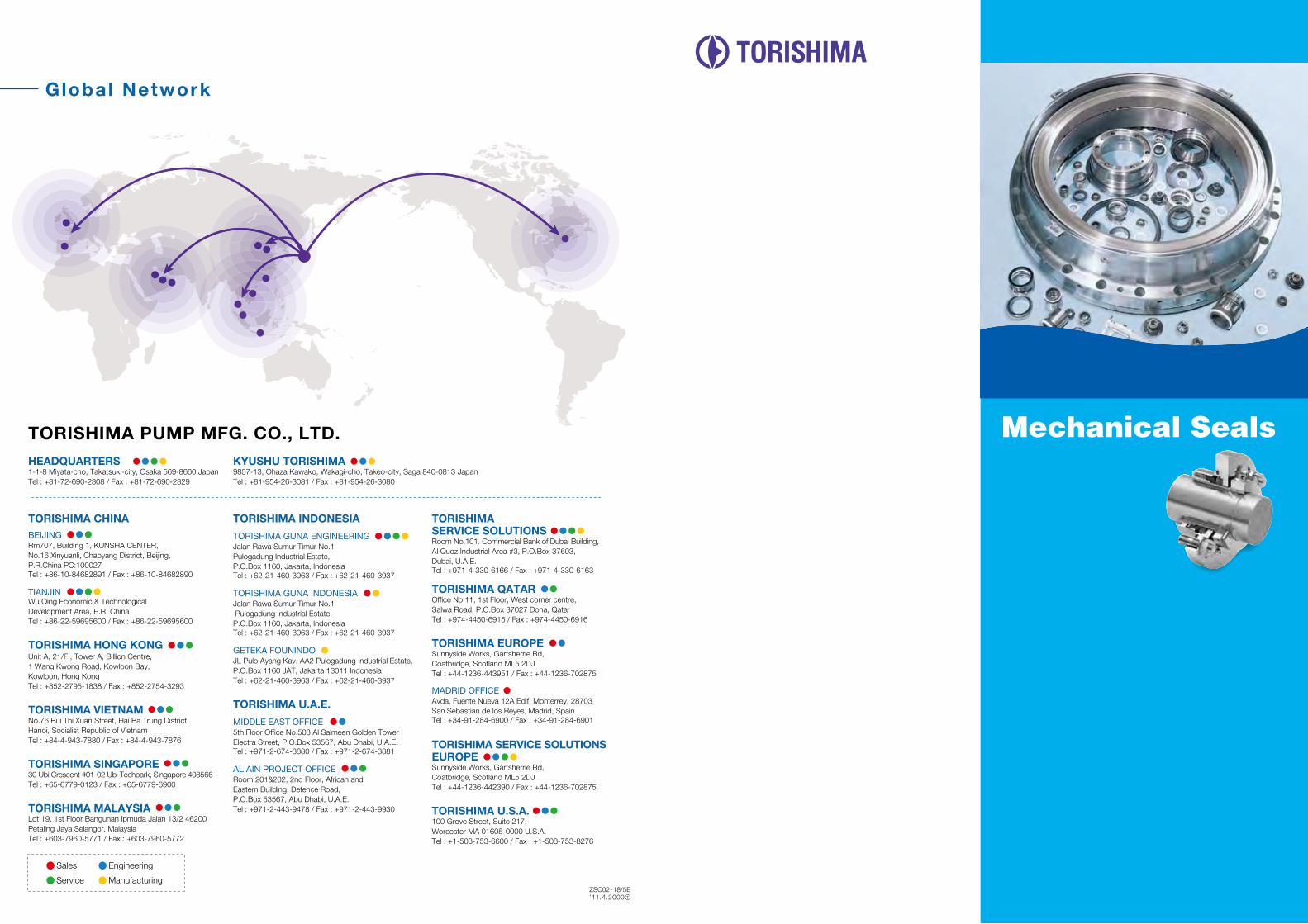
Mechanical Seals
Global Network
ZSC02・18/5E’11.4.2000 T
TORISHIMA CHINABEIJINGRm707, Building 1, KUNSHA CENTER, No.16 Xinyuanli, Chaoyang District, Beijing, P.R.China PC:100027Tel : +86-10-84682891 / Fax : +86-10-84682890
TIANJINWu Qing Economic & TechnologicalDevelopment Area, P.R. ChinaTel : +86-22-59695600 / Fax : +86-22-59695600
TORISHIMA HONG KONGUnit A, 21/F., Tower A, Billion Centre,1 Wang Kwong Road, Kowloon Bay,Kowloon, Hong KongTel : +852-2795-1838 / Fax : +852-2754-3293
TORISHIMA VIETNAMNo.76 Bui Thi Xuan Street, Hai Ba Trung District, Hanoi, Socialist Republic of VietnamTel : +84-4-943-7880 / Fax : +84-4-943-7876
TORISHIMA SINGAPORE30 Ubi Crescent #01-02 Ubi Techpark, Singapore 408566Tel : +65-6779-0123 / Fax : +65-6779-6900
TORISHIMA MALAYSIALot 19, 1st Floor Bangunan Ipmuda Jalan 13/2 46200Petaling Jaya Selangor, MalaysiaTel : +603-7960-5771 / Fax : +603-7960-5772
HEADQUARTERS1-1-8 Miyata-cho, Takatsuki-city, Osaka 569-8660 JapanTel : +81-72-690-2308 / Fax : +81-72-690-2329
KYUSHU TORISHIMA9857-13, Ohaza Kawako, Wakagi-cho, Takeo-city, Saga 840-0813 JapanTel : +81-954-26-3081 / Fax : +81-954-26-3080
TORISHIMA SERVICE SOLUTIONSRoom No.101. Commercial Bank of Dubai Building,Al Quoz Industrial Area #3, P.O.Box 37603, Dubai, U.A.E. Tel : +971-4-330-6166 / Fax : +971-4-330-6163
TORISHIMA QATAROffice No.11, 1st Floor, West corner centre,Salwa Road, P.O.Box 37027 Doha, QatarTel : +974-4450-6915 / Fax : +974-4450-6916
TORISHIMA EUROPESunnyside Works, Gartsherrie Rd, Coatbridge, Scotland ML5 2DJTel : +44-1236-443951 / Fax : +44-1236-702875
MADRID OFFICEAvda, Fuente Nueva 12A Edif, Monterrey, 28703 San Sebastian de los Reyes, Madrid, SpainTel : +34-91-284-6900 / Fax : +34-91-284-6901
TORISHIMA SERVICE SOLUTIONS EUROPESunnyside Works, Gartsherrie Rd, Coatbridge, Scotland ML5 2DJTel : +44-1236-442390 / Fax : +44-1236-702875
TORISHIMA U.S.A.100 Grove Street, Suite 217, Worcester MA 01605-0000 U.S.A.Tel : +1-508-753-6600 / Fax : +1-508-753-8276
TORISHIMA INDONESIA
TORISHIMA GUNA ENGINEERINGJalan Rawa Sumur Timur No.1 Pulogadung Industrial Estate,P.O.Box 1160, Jakarta, IndonesiaTel : +62-21-460-3963 / Fax : +62-21-460-3937
TORISHIMA GUNA INDONESIAJalan Rawa Sumur Timur No.1 Pulogadung Industrial Estate,P.O.Box 1160, Jakarta, IndonesiaTel : +62-21-460-3963 / Fax : +62-21-460-3937
GETEKA FOUNINDOJL Pulo Ayang Kav. AA2 Pulogadung Industrial Estate,P.O.Box 1160 JAT, Jakarta 13011 IndonesiaTel : +62-21-460-3963 / Fax : +62-21-460-3937
TORISHIMA U.A.E.
MIDDLE EAST OFFICE5th Floor Office No.503 Al Salmeen Golden TowerElectra Street, P.O.Box 53567, Abu Dhabi, U.A.E.Tel : +971-2-674-3880 / Fax : +971-2-674-3881
AL AIN PROJECT OFFICERoom 201&202, 2nd Floor, African and Eastern Building, Defence Road, P.O.Box 53567, Abu Dhabi, U.A.E.Tel : +971-2-443-9478 / Fax : +971-2-443-9930
TORISHIMA PUMP MFG. CO., LTD.
Sales Engineering
Service Manufacturing
Basic Structure of Mechanical Seal
M B 2 7 0 4 C B 1 A H L 0 9 0
LU1000 Series ● ● ● ● ● ● ● ● ● ● ● ● ● ● ● ● ●
LD1000 Series(Double seal)
●● ●
HU2000 Series(Unbalanced type)
● ● ● ● ● ● ● ● ●
HB2000 Series(Balanced type)
● ● ● ● ● ● ● ● ● ● ● ● ●
MU2000 Series(Unbalanced type)
● ● ● ● ● ● ● ● ● ●
MB2000 Series(Balanced type)
● ● ● ● ● ● ●
●
●
●
● ●
●
●
●
●
●
● ●
●
●
●
● ● ●
●
●
●
●
MT2700(Balanced type)
● ● ●
MB2500(Balanced type)
● ● ●
MB2704CN(Inside rotating type)
● ● ● ● ● ● ● ● ● ● ● ● ● ● ● ● ● ● ● ● ● ●
● ●
●
● ●
MB8500CN(Stationary inside type)
● ● ● ● ● ● ● ●
●●● ●
MB2400CN(Outside rotating type)
● ● ● ● ● ● ● ●●●● ● ● ●
MB2901● ● ● ● ● ●●● ●● ● ● ● ● ● ●
MU2922● ● ● ●
MT9200● ● ● ●
MT4100(Balanced type)
For hydraulic turbinesFor submersible sand pumps
●● ● ● ● ● ● ● ●
●
●
●● ●
●
●
1000/General
2000/Process
3000/Marine
4000/ Submersiblepump
Submersible bearing
Hydraulic turbine
5000/
6000/
7000/Vessel
8000/Process
9000/Special
NBR SDSS
SUS329J4L
SUS329J1
SUS403
SUS304
SUS316
SUS316L
Carpenter 20
Hastelloy
Worthite
A
B
C
1
2
3
4
5
7
8
9
X
A
B
C
D
E
F
G
H
I
J
K
L
M
EPDM(Ethylene propylene rubber)
CR(Neoprene)
MQ(Silicon rubber)
FKM(Fluoro rubber)FFKM(Perfluoroelastomer)
PTFE(Polytetrafluoroethylene)
Other
Undefined
Other
Undefined
SUS403
SUS316
N
P
Q
R
S
T
U
V
W
Y
Z
X
mm
L
H
M
U
B
D
W
T
N
B
C
A
B
D
G
J
N
R
S
Z
1
2
3
4
5
6
8
9
X
MB2704CZ(Inside rotating type, with pumping ring)
(Stationary balanced type, non-flushing)
(Stationary balanced type, dry running application)
(Stationary balanced type, dry running application)
(Stationary inside type, with pumping ring)
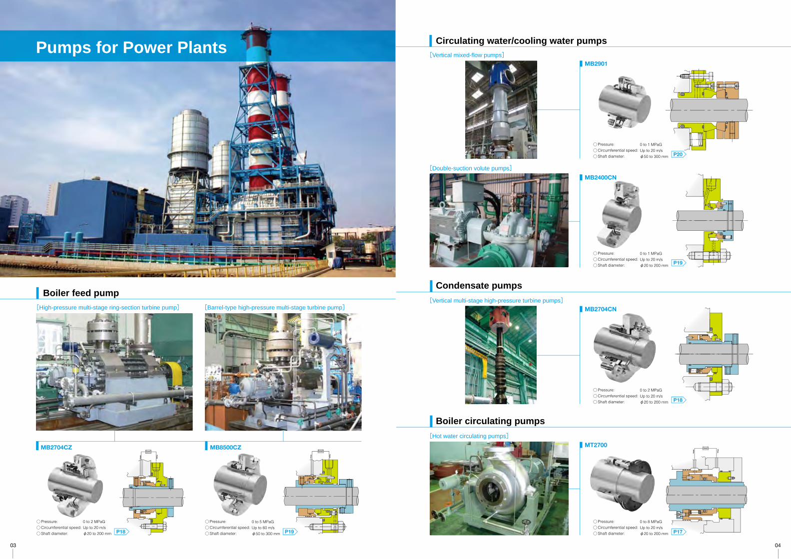
MB8500CZ
P15
P18
P16
P17
P19
P20
P21
P21
Carpenter 20
Special carbon
Stellite
Special stainless steel
Copper alloy
Carbon
PTFE (Polytetrafluoroethylene)
Carbon fit (including press fit)
Niresist
SiC
SiC fit (including press fit)
Ceramic
Suehiro
Tungsten carbide coating
Ceramic coating
Standard tungsten carbide brazed
Standard solid tungsten carbide
Special tungsten carbide brazed
Special solid tungsten carbide
Other
Undefined
Standard tungsten carbide fit(including press fit)
Special tungsten carbide fit(including press fit)
Main structuralmaterial
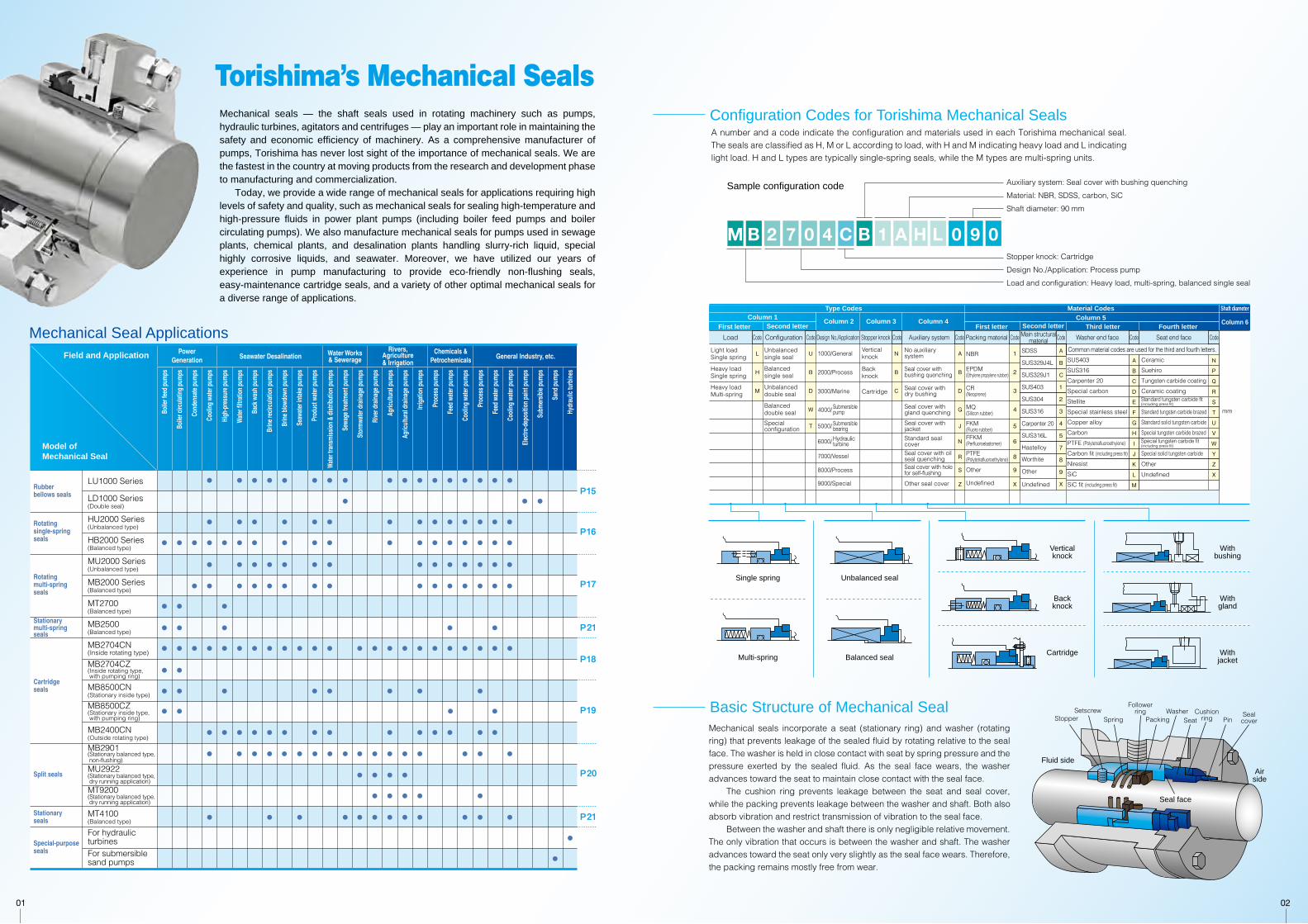
Torishima’s Mechanical Seals
Mechanical Seal Applications
Mechanical seals — the shaft seals used in rotating machinery such as pumps, hydraulic turbines, agitators and centrifuges — play an important role in maintaining the safety and economic efficiency of machinery. As a comprehensive manufacturer of pumps, Torishima has never lost sight of the importance of mechanical seals. We are the fastest in the country at moving products from the research and development phase to manufacturing and commercialization.
Today, we provide a wide range of mechanical seals for applications requiring high levels of safety and quality, such as mechanical seals for sealing high-temperature and high-pressure fluids in power plant pumps (including boiler feed pumps and boiler circulating pumps). We also manufacture mechanical seals for pumps used in sewage plants, chemical plants, and desalination plants handling slurry-rich liquid, special highly corrosive liquids, and seawater. Moreover, we have utilized our years of experience in pump manufacturing to provide eco-friendly non-flushing seals, easy-maintenance cartridge seals, and a variety of other optimal mechanical seals for a diverse range of applications.
Rubber bellows seals
Rotatingsingle-springseals
Rotatingmulti-springseals
Cartridgeseals
Split seals
Stationaryseals
Special-purpose seals
Stationarymulti-springseals
Boile
r fee
d pu
mps
Boile
r circ
ulat
ing
pum
ps
Cond
ensa
te p
umps
Cool
ing
wate
r pum
ps
Rive
r dra
inag
e pum
ps
Agric
ultu
ral p
umps
Agric
ultu
ral d
rain
age p
umps
Irrig
atio
n pu
mps
Wat
er tr
ansm
issio
n &
dist
ribut
ion
pum
ps
Sewa
ge tr
eatm
ent p
umps
Stor
mwa
ter d
rain
age p
umps
Proc
ess p
umps
Feed
wat
er p
umps
Cool
ing
wate
r pum
ps
High
-pre
ssur
e pum
ps
Wat
er fi
ltrat
ion
pum
ps
Back
was
h pu
mps
Brin
e rec
ircul
atio
n pu
mps
Brin
e blo
wdow
n pu
mps
Seaw
ater
inta
ke p
umps
Prod
uct w
ater
pum
ps
Proc
ess p
umps
Feed
wat
er p
umps
Cool
ing
wate
r pum
ps
Elec
tro-d
epos
ition
pain
t pum
ps
Subm
ersib
le pu
mps
Sand
pum
ps
Hydr
aulic
turb
ines
Field and Application PowerGeneration Seawater Desalination General Industry, etc.
Chemicals &Petrochemicals
Water Works& Sewerage
Rivers,Agriculture& Irrigation
Model of Mechanical Seal
Configuration Codes for Torishima Mechanical SealsA number and a code indicate the configuration and materials used in each Torishima mechanical seal. The seals are classified as H, M or L according to load, with H and M indicating heavy load and L indicating light load. H and L types are typically single-spring seals, while the M types are multi-spring units.
Auxiliary system: Seal cover with bushing quenching
Material: NBR, SDSS, carbon, SiC
Shaft diameter: 90 mm
Stopper knock: Cartridge
Design No./Application: Process pump
Load and configuration: Heavy load, multi-spring, balanced single seal
Sample configuration code
Type Codes Material Codes Shaft diameterColumn 5 Column 6
Column 1 Column 2 Column 3 Column 4First letter First letter Fourth letterThird letterSecond letterSecond letter
Load Auxiliary system Packing material Washer end face Seat end face
Common material codes are used for the third and fourth letters.
Stopper knockDesign No./ApplicationCode Code Code Code Code Code CodeCode
Light loadSingle spring
Unbalanced single seal
Balancedsingle seal
Unbalanceddouble seal
Balanceddouble seal
Specialconfiguration
Heavy loadSingle spring
Heavy loadMulti-spring
Configuration
Vertical knock
Backknock
Cartridge
No auxiliary system
Seal cover with bushing quenching
Seal cover with dry bushing
Seal cover with gland quenching
Standard seal cover
Seal cover with jacket
Other seal cover
Seal cover with oil seal quenchingSeal cover with hole for self-flushing
Single spring
Multi-spring
Unbalanced seal
Verticalknock
Backknock
Cartridge
Fluid side
Seal face
Airside
StopperSetscrew
Spring
Followerring
PackingWasher
Seat PinSealcover
Cushionring
Withbushing
Withgland
WithjacketBalanced seal
Mechanical seals incorporate a seat (stationary ring) and washer (rotating ring) that prevents leakage of the sealed fluid by rotating relative to the seal face. The washer is held in close contact with seat by spring pressure and the pressure exerted by the sealed fluid. As the seal face wears, the washer advances toward the seat to maintain close contact with the seal face.
The cushion ring prevents leakage between the seat and seal cover, while the packing prevents leakage between the washer and shaft. Both also absorb vibration and restrict transmission of vibration to the seal face.
Between the washer and shaft there is only negligible relative movement. The only vibration that occurs is between the washer and shaft. The washer advances toward the seat only very slightly as the seal face wears. Therefore, the packing remains mostly free from wear.
01 02
03 04
0 to 5 MPaG
Up to 60 m/s
50 to 300 mm
0 to 2 MPaG
Up to 20 m/s
20 to 200 mm
MB2704CZ MB8500CZ
MB2400CN
MT2700
MB2901
MB2704CN
0 to 1 MPaG
Up to 20 m/s
50 to 300 mm
0 to 1 MPaG
Up to 20 m/s
20 to 200 mm
0 to 2 MPaG
Up to 20 m/s
20 to 200 mm
0 to 8 MPaG
Up to 20 m/s
20 to 200 mm
Boiler feed pump
Pressure:
Circumferential speed:
Shaft diameter:
Pressure:
Circumferential speed:
Shaft diameter:
Pressure:
Circumferential speed:
Shaft diameter:
Pressure:
Circumferential speed:
Shaft diameter:
Pressure:
Circumferential speed:
Shaft diameter:
Pressure:
Circumferential speed:
Shaft diameter:
Circulating water/cooling water pumps[Vertical mixed-flow pumps]
Condensate pumps
[Double-suction volute pumps]
[Vertical multi-stage high-pressure turbine pumps]
Boiler circulating pumps[Hot water circulating pumps]
[High-pressure multi-stage ring-section turbine pump] [Barrel-type high-pressure multi-stage turbine pump]
Pumps for Power Plants
P18 P19
P20
P19
P18
P17
05 06
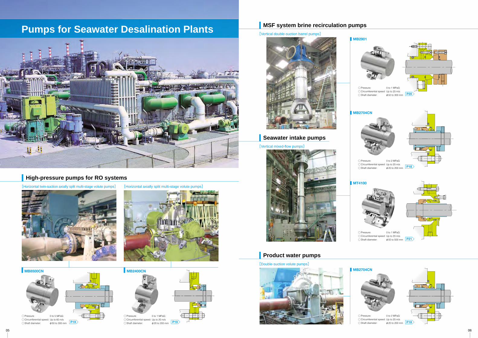
MB8500CN MB2400CN
MB2901
MB2704CN
MT4100
MB2704CN
P19 P19 P18
0 to 5 MPaG
Up to 60 m/s
50 to 300 mm
0 to 1 MPaG
Up to 20 m/s
20 to 200 mm
0 to 1 MPaG
Up to 20 m/s
50 to 300 mm
0 to 2 MPaG
Up to 20 m/s
20 to 200 mm
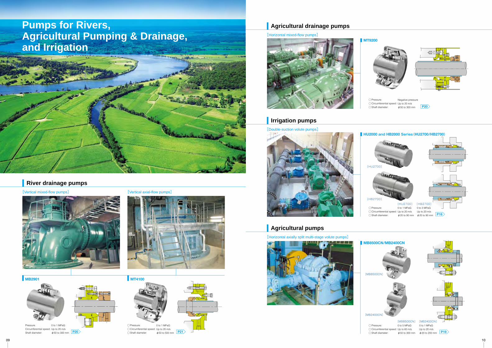
0 to 1 MPaG
Up to 20 m/s
50 to 500 mm
0 to 2 MPaG
Up to 20 m/s
20 to 200 mm
P21
P18
P20
[Vertical double-suction barrel pumps]
[Vertical mixed-flow pumps]
[Double-suction volute pumps]
MSF system brine recirculation pumps
Product water pumps
Seawater intake pumps
Pressure:
Circumferential speed:
Shaft diameter:
Pressure:
Circumferential speed:
Shaft diameter:
Pressure:
Circumferential speed:
Shaft diameter:
Pressure:
Circumferential speed:
Shaft diameter:
[Horizontal axially split multi-stage volute pumps][Horizontal twin-suction axially split multi-stage volute pumps]
High-pressure pumps for RO systems
Pumps for Seawater Desalination Plants
Pressure:
Circumferential speed:
Shaft diameter:
Pressure:
Circumferential speed:
Shaft diameter:
07 08
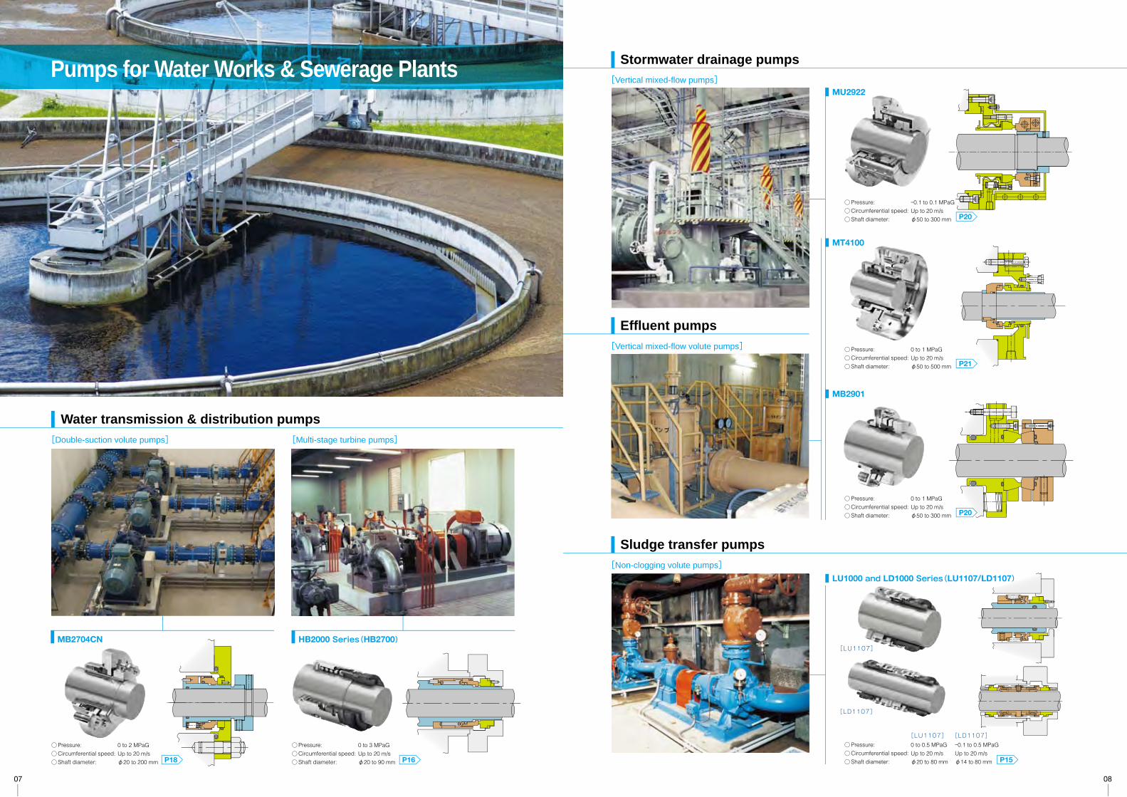
MB2704CN
MU2922
LU1000 and LD1000 Series(LU1107/LD1107)
MT4100
MB2901
[LU1107] [LD1107]
[LD1107]
[LU1107]
0 to 2 MPaG
Up to 20 m/s
20 to 200 mm
0 to 3 MPaG
Up to 20 m/s
20 to 90 mm
0.1 to 0.1 MPaG
Up to 20 m/s
50 to 300 mm
0 to 1 MPaG
Up to 20 m/s
50 to 500 mm
0 to 1 MPaG
Up to 20 m/s
50 to 300 mm
0 to 0.5 MPaG
Up to 20 m/s
20 to 80 mm
0.1 to 0.5 MPaG
Up to 20 m/s
14 to 80 mmP16P18 P15
P20
P21
P20
Pumps for Water Works & Sewerage Plants
Pressure:
Circumferential speed:
Shaft diameter:
Pressure:
Circumferential speed:
Shaft diameter:
[Multi-stage turbine pumps]
HB2000 Series(HB2700)
[Double-suction volute pumps]
Water transmission & distribution pumps
[Vertical mixed-flow pumps]
[Vertical mixed-flow volute pumps]
[Non-clogging volute pumps]
Stormwater drainage pumps
Sludge transfer pumps
Effluent pumps
Pressure:
Circumferential speed:
Shaft diameter:
Pressure:
Circumferential speed:
Shaft diameter:
Pressure:
Circumferential speed:
Shaft diameter:
Pressure:
Circumferential speed:
Shaft diameter:
09 10
MT9200
MB8500CN/MB2400CN
[HU2700] [HB2700]
[MB8500CN] [MB2400CN]
[HU2700]
[HB2700]
[MB8500CN]
[MB2400CN]
0 to 1 MPaG
Up to 20 m/s
50 to 500 mm
0 to 1 MPaG
Up to 20 m/s
50 to 300 mm
Negative pressure
Up to 20 m/s
50 to 300 mm
0 to 1 MPaG
Up to 20 m/s
20 to 90 mm
0 to 3 MPaG
Up to 20 m/s
20 to 90 mm
0 to 5 MPaG
Up to 60 m/s
50 to 300 mm
0 to 1 MPaG
Up to 20 m/s
20 to 200 mm
[Vertical axial-flow pumps]
[Horizontal mixed-flow pumps]
[Double-suction volute pumps]
[Horizontal axially split multi-stage volute pumps]
[Vertical mixed-flow pumps]
Agricultural drainage pumps
Irrigation pumps
Agricultural pumps
River drainage pumps
Pumps for Rivers, Agricultural Pumping & Drainage, and Irrigation
Pressure:
Circumferential speed:
Shaft diameter:
Pressure:
Circumferential speed:
Shaft diameter:
Pressure:
Circumferential speed:
Shaft diameter:
HU2000 and HB2000 Series(HU2700/HB2700)
Pressure:
Circumferential speed:
Shaft diameter:
Pressure:
Circumferential speed:
Shaft diameter:
MB2901 MT4100
P19
P16
P20
P21P20
11 12
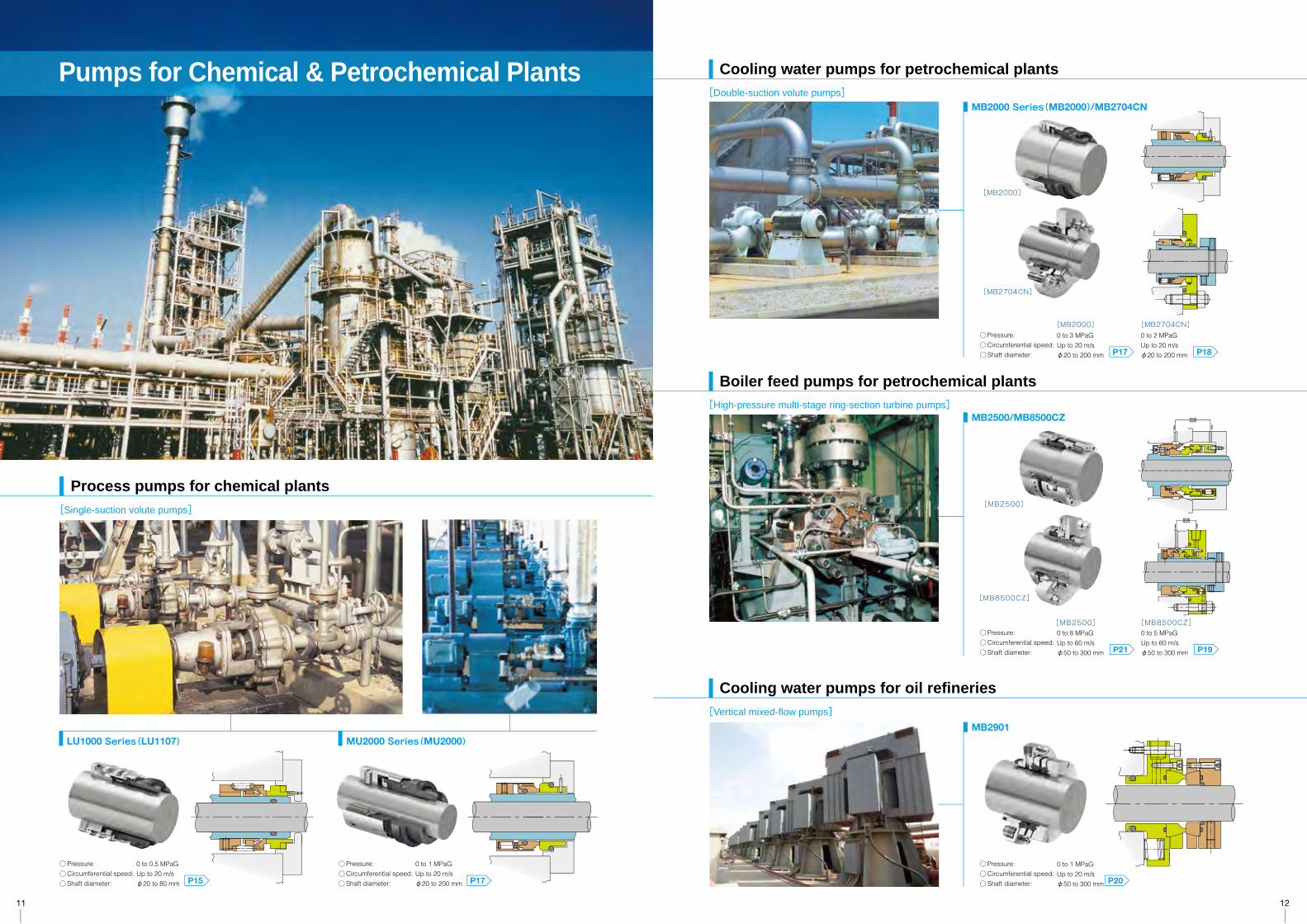
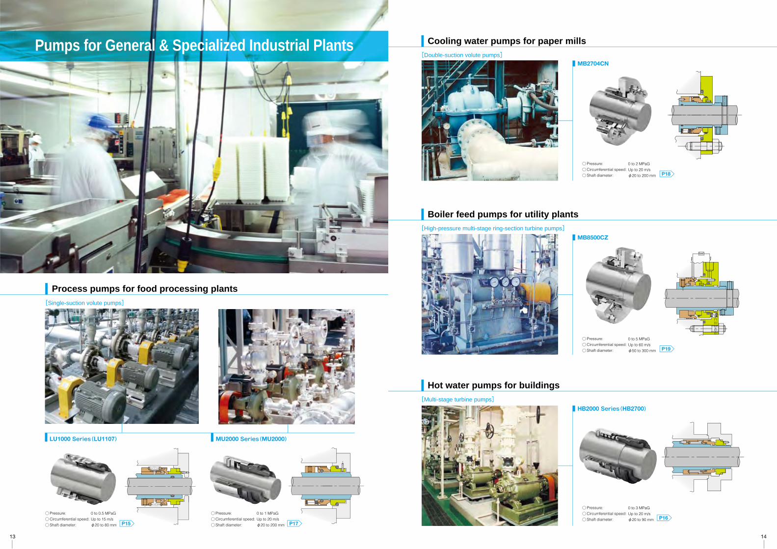
LU1000 Series(LU1107) MU2000 Series(MU2000)
0 to 0.5 MPaG
Up to 20 m/s
20 to 80 mm
0 to 1 MPaG
Up to 20 m/s
20 to 200 mm
MB2000 Series(MB2000)/MB2704CN
MB2500/MB8500CZ
MB2901
[MB2500] [MB8500CZ]
[MB2500]
[MB8500CZ]
P15 P17 P20
P17 P18
0 to 3 MPaG
Up to 20 m/s
20 to 200 mm
0 to 2 MPaG
Up to 20 m/s
20 to 200 mm
P21 P19
0 to 8 MPaG
Up to 60 m/s
50 to 300 mm
0 to 5 MPaG
Up to 60 m/s
50 to 300 mm
0 to 1 MPaG
Up to 20 m/s
50 to 300 mm
[MB2000] [MB2704CN]
[MB2000]
[MB2704CN]
[Double-suction volute pumps]
[High-pressure multi-stage ring-section turbine pumps]
[Vertical mixed-flow pumps]
[Single-suction volute pumps]
Pumps for Chemical & Petrochemical Plants Cooling water pumps for petrochemical plants
Boiler feed pumps for petrochemical plants
Cooling water pumps for oil refineries
Process pumps for chemical plants
Pressure:
Circumferential speed:
Shaft diameter:
Pressure:
Circumferential speed:
Shaft diameter:
Pressure:
Circumferential speed:
Shaft diameter:
Pressure:
Circumferential speed:
Shaft diameter:
Pressure:
Circumferential speed:
Shaft diameter:
13 14
MB2704CN
MB8500CZ
HB2000 Series(HB2700)
0 to 2 MPaG
Up to 20 m/s
20 to 200 mm
0 to 5 MPaG
Up to 60 m/s
50 to 300 mm
0 to 3 MPaG
Up to 20 m/s
20 to 90 mm
0 to 0.5 MPaG
Up to 15 m/s
20 to 80 mm
0 to 1 MPaG
Up to 20 m/s
20 to 200 mm
Pumps for General & Specialized Industrial Plants
[High-pressure multi-stage ring-section turbine pumps]
[Multi-stage turbine pumps]
[Single-suction volute pumps]
LU1000 Series(LU1107)
Cooling water pumps for paper mills
Boiler feed pumps for utility plants
Hot water pumps for buildings
Process pumps for food processing plants
MU2000 Series(MU2000)
Pressure:
Circumferential speed:
Shaft diameter:
Pressure:
Circumferential speed:
Shaft diameter:
Pressure:
Circumferential speed:
Shaft diameter:
Pressure:
Circumferential speed:
Shaft diameter:
Pressure:
Circumferential speed:
Shaft diameter:
[Double-suction volute pumps]
P15 P17P16
P19
P18
15 16
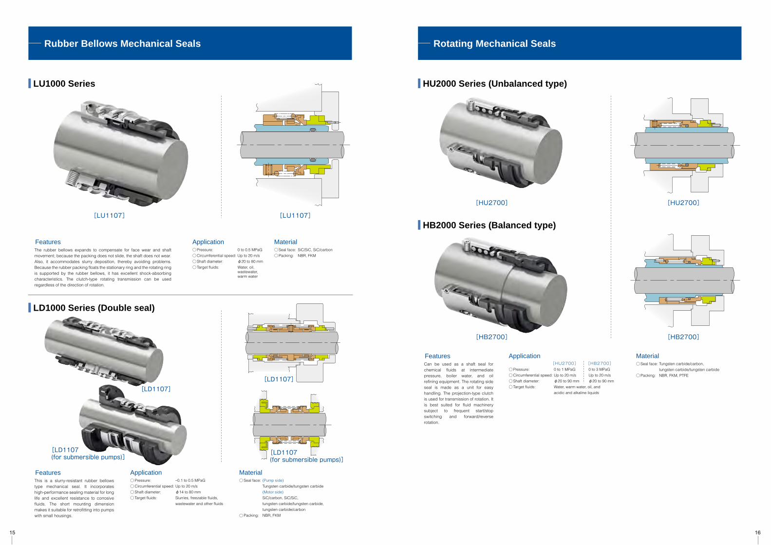
Features Application
Application
Material
Material
Application Material
LD1000 Series (Double seal)
The rubber bellows expands to compensate for face wear and shaft movement; because the packing does not slide, the shaft does not wear. Also, it accommodates slurry deposition, thereby avoiding problems. Because the rubber packing floats the stationary ring and the rotating ring is supported by the rubber bellows, it has excellent shock-absorbing characteristics. The clutch-type rotating transmission can be used regardless of the direction of rotation.
FeaturesThis is a slurry-resistant rubber bellows type mechanical seal. It incorporates high-performance sealing material for long life and excellent resistance to corrosive fluids. The short mounting dimension makes it suitable for retrofitting into pumps with small housings.
FeaturesCan be used as a shaft seal for chemical fluids at intermediate pressure, boiler water, and oil refining equipment. The rotating side seal is made as a unit for easy handling. The projection-type clutch is used for transmission of rotation. It is best suited for fluid machinery subject to frequent start/stop switching and forward/reverse rotation.
[HU2700]
[HB2700]
[HU2700]
[HB2700]
[HU2700] [HB2700]
Rubber Bellows Mechanical Seals Rotating Mechanical Seals
LU1000 Series HU2000 Series (Unbalanced type)
HB2000 Series (Balanced type)
Pressure:
Circumferential speed:
Shaft diameter:
Target fluids:
0 to 0.5 MPaG
Up to 20 m/s
20 to 80 mm
Water, oil, wastewater, warm water
Pressure:
Circumferential speed:
Shaft diameter:
Target fluids:
0.1 to 0.5 MPaG
Up to 20 m/s
14 to 80 mm
Slurries, freezable fluids,
wastewater and other fluids
Seal face:
Packing:
SiC/SiC, SiC/carbon
NBR, FKM
Seal face:
Packing:
(Pump side)
Tungsten carbide/tungsten carbide
(Motor side)
SiC/carbon, SiC/SiC,
tungsten carbide/tungsten carbide,
tungsten carbide/carbon
NBR, FKM
Pressure:
Circumferential speed:
Shaft diameter:
Target fluids:
0 to 1 MPaG
Up to 20 m/s
20 to 90 mm
Water, warm water, oil, and
acidic and alkaline liquids
0 to 3 MPaG
Up to 20 m/s
20 to 90 mm
Seal face:
Packing:
Tungsten carbide/carbon,
tungsten carbide/tungsten carbide
NBR, FKM, PTFE
[LU1107]
[LD1107][LD1107]
[LD1107(for submersible pumps)]
[LD1107(for submersible pumps)]
[LU1107]
17 18
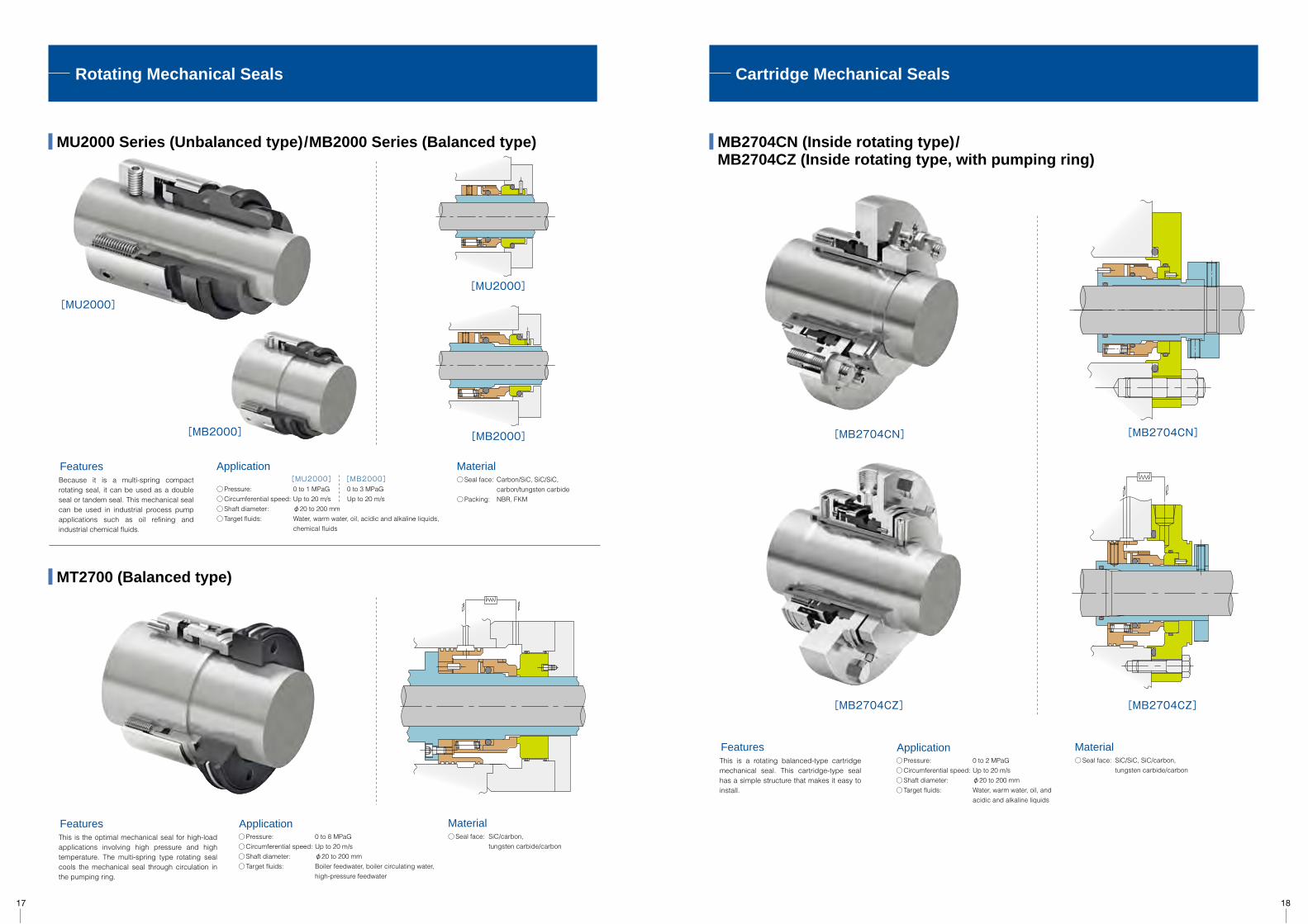
FeaturesThis is a rotating balanced-type cartridge mechanical seal. This cartridge-type seal has a simple structure that makes it easy to install.
[MU2000]
[MB2704CN]
[MB2704CZ]
[MB2704CN]
[MB2704CZ]
[MB2000]
Features ApplicationThis is the optimal mechanical seal for high-load applications involving high pressure and high temperature. The multi-spring type rotating seal cools the mechanical seal through circulation in the pumping ring.
FeaturesBecause it is a multi-spring compact rotating seal, it can be used as a double seal or tandem seal. This mechanical seal can be used in industrial process pump applications such as oil refining and industrial chemical fluids.
[MU2000]
[MB2000]
Application Material
Material
Application Material
[MU2000] [MB2000]
Rotating Mechanical Seals Cartridge Mechanical Seals
MB2704CN (Inside rotating type) / MB2704CZ (Inside rotating type, with pumping ring)
MT2700 (Balanced type)
MU2000 Series (Unbalanced type) /MB2000 Series (Balanced type)
Pressure:
Circumferential speed:
Shaft diameter:
Target fluids:
0 to 1 MPaG
Up to 20 m/s
20 to 200 mm
Water, warm water, oil, acidic and alkaline liquids,
chemical fluids
Pressure:
Circumferential speed:
Shaft diameter:
Target fluids:
0 to 8 MPaG
Up to 20 m/s
20 to 200 mm
Boiler feedwater, boiler circulating water,
high-pressure feedwater
0 to 3 MPaG
Up to 20 m/s
Seal face:
Packing:
Carbon/SiC, SiC/SiC,
carbon/tungsten carbide
NBR, FKM
Seal face: SiC/carbon,
tungsten carbide/carbon
Pressure:
Circumferential speed:
Shaft diameter:
Target fluids:
0 to 2 MPaG
Up to 20 m/s
20 to 200 mm
Water, warm water, oil, and
acidic and alkaline liquids
Seal face: SiC/SiC, SiC/carbon,
tungsten carbide/carbon
19 20
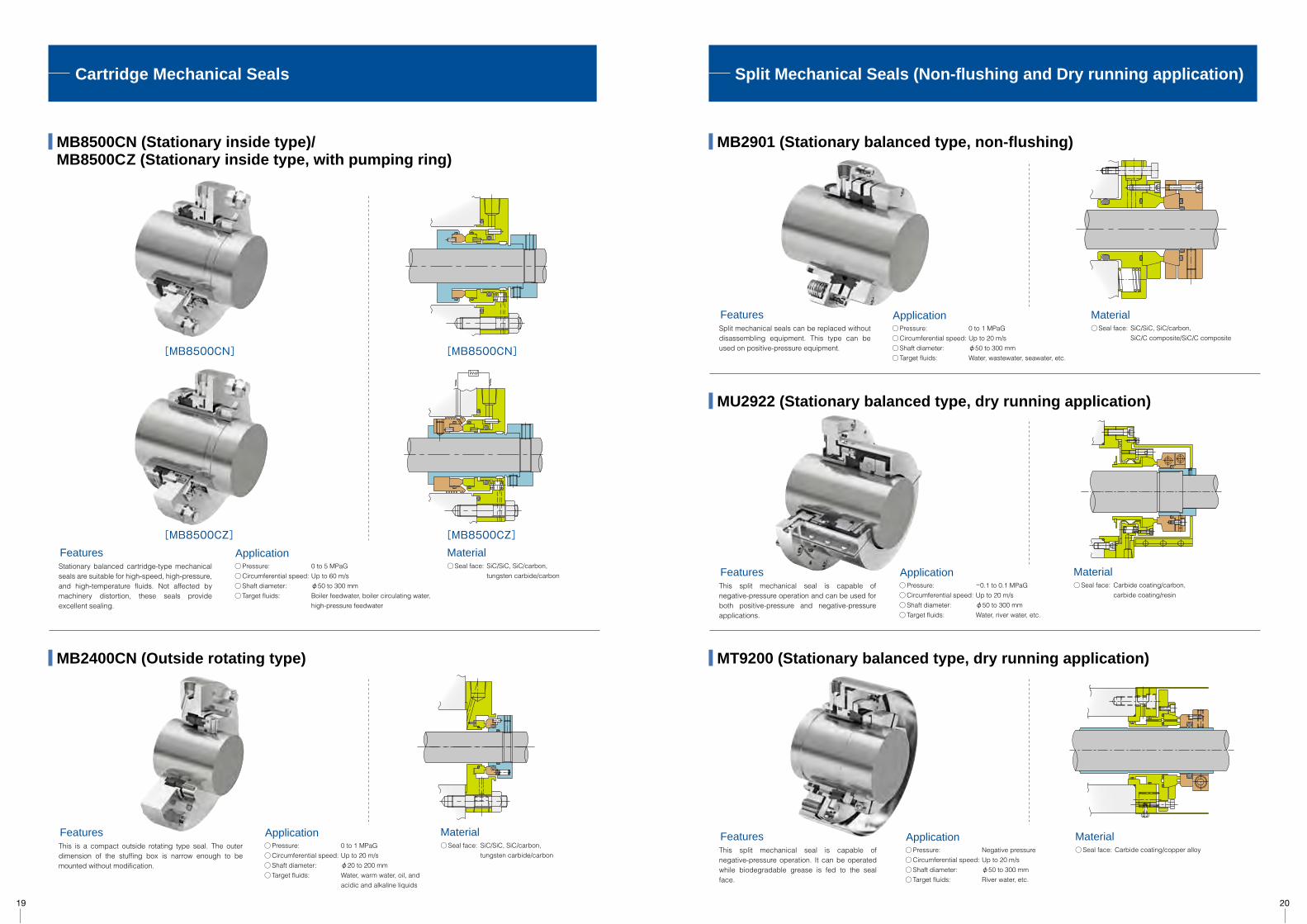
MB2400CN (Outside rotating type)
FeaturesStationary balanced cartridge-type mechanical seals are suitable for high-speed, high-pressure, and high-temperature fluids. Not affected by machinery distortion, these seals provide excellent sealing.
FeaturesThis is a compact outside rotating type seal. The outer dimension of the stuffing box is narrow enough to be mounted without modification.
MB8500CN (Stationary inside type)/ MB8500CZ (Stationary inside type, with pumping ring)
[MB8500CN]
[MB8500CZ]
[MB8500CN]
[MB8500CZ]
MT9200 (Stationary balanced type, dry running application)
FeaturesThis split mechanical seal is capable of negative-pressure operation. It can be operated while biodegradable grease is fed to the seal face.
MU2922 (Stationary balanced type, dry running application)
FeaturesThis split mechanical seal is capable of negative-pressure operation and can be used for both positive-pressure and negative-pressure applications.
MB2901 (Stationary balanced type, non-flushing)
FeaturesSplit mechanical seals can be replaced without disassembling equipment. This type can be used on positive-pressure equipment.
Application Material
Application Material
Application Material
Application Material
Application Material
Cartridge Mechanical Seals Split Mechanical Seals (Non-flushing and Dry running application)
Pressure:
Circumferential speed:
Shaft diameter:
Target fluids:
0 to 5 MPaG
Up to 60 m/s
50 to 300 mm
Boiler feedwater, boiler circulating water,
high-pressure feedwater
Seal face: SiC/SiC, SiC/carbon,
tungsten carbide/carbon
Pressure:
Circumferential speed:
Shaft diameter:
Target fluids:
0 to 1 MPaG
Up to 20 m/s
20 to 200 mm
Water, warm water, oil, and
acidic and alkaline liquids
Seal face: SiC/SiC, SiC/carbon,
tungsten carbide/carbon
Pressure:
Circumferential speed:
Shaft diameter:
Target fluids:
0 to 1 MPaG
Up to 20 m/s
50 to 300 mm
Water, wastewater, seawater, etc.
Seal face: SiC/SiC, SiC/carbon,
SiC/C composite/SiC/C composite
Pressure:
Circumferential speed:
Shaft diameter:
Target fluids:
-0.1 to 0.1 MPaG
Up to 20 m/s
50 to 300 mm
Water, river water, etc.
Seal face: Carbide coating/carbon,
carbide coating/resin
Pressure:
Circumferential speed:
Shaft diameter:
Target fluids:
Negative pressure
Up to 20 m/s
50 to 300 mm
River water, etc.
Seal face: Carbide coating/copper alloy
21 22
Application Material
Application Material
Stationary Mechanical Seals
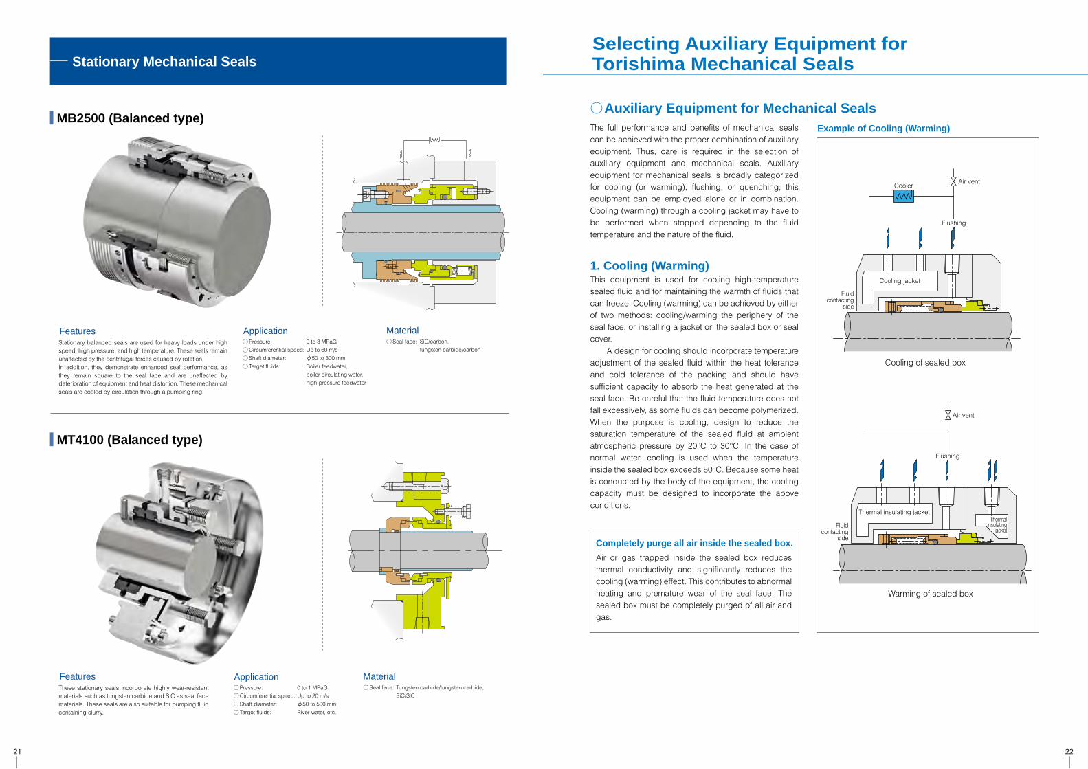
FeaturesStationary balanced seals are used for heavy loads under high speed, high pressure, and high temperature. These seals remain unaffected by the centrifugal forces caused by rotation.In addition, they demonstrate enhanced seal performance, as they remain square to the seal face and are unaffected by deterioration of equipment and heat distortion. These mechanical seals are cooled by circulation through a pumping ring.
FeaturesThese stationary seals incorporate highly wear-resistant materials such as tungsten carbide and SiC as seal face materials. These seals are also suitable for pumping fluid containing slurry.
Pressure:
Circumferential speed:
Shaft diameter:
Target fluids:
0 to 8 MPaG
Up to 60 m/s
50 to 300 mm
Boiler feedwater,
boiler circulating water,
high-pressure feedwater
Seal face: SiC/carbon,
tungsten carbide/carbon
Pressure:
Circumferential speed:
Shaft diameter:
Target fluids:
0 to 1 MPaG
Up to 20 m/s
50 to 500 mm
River water, etc.
Seal face: Tungsten carbide/tungsten carbide,
SiC/SiC
MB2500 (Balanced type)
MT4100 (Balanced type)
Auxiliary Equipment for Mechanical Seals
Selecting Auxiliary Equipment forTorishima Mechanical Seals
Example of Cooling (Warming) The full performance and benefits of mechanical seals can be achieved with the proper combination of auxiliary equipment. Thus, care is required in the selection of auxiliary equipment and mechanical seals. Auxiliary equipment for mechanical seals is broadly categorized for cooling (or warming), flushing, or quenching; this equipment can be employed alone or in combination. Cooling (warming) through a cooling jacket may have to be performed when stopped depending to the fluid temperature and the nature of the fluid.
1. Cooling (Warming)This equipment is used for cooling high-temperature sealed fluid and for maintaining the warmth of fluids that can freeze. Cooling (warming) can be achieved by either of two methods: cooling/warming the periphery of the seal face; or installing a jacket on the sealed box or seal cover.
A design for cooling should incorporate temperature adjustment of the sealed fluid within the heat tolerance and cold tolerance of the packing and should have sufficient capacity to absorb the heat generated at the seal face. Be careful that the fluid temperature does not fall excessively, as some fluids can become polymerized. When the purpose is cooling, design to reduce the saturation temperature of the sealed fluid at ambient atmospheric pressure by 20°C to 30°C. In the case of normal water, cooling is used when the temperature inside the sealed box exceeds 80°C. Because some heat is conducted by the body of the equipment, the cooling capacity must be designed to incorporate the above conditions.
Air or gas trapped inside the sealed box reduces thermal conductivity and significantly reduces the cooling (warming) effect. This contributes to abnormal heating and premature wear of the seal face. The sealed box must be completely purged of all air and gas.
Completely purge all air inside the sealed box.
Flushing
Cooler
Flushing
Fluidcontacting
side
Fluidcontacting
side
Air vent
Cooling jacket
Thermal insulating jacket
Cooling of sealed box
Warming of sealed box
Air vent
Thermalinsulating
jacket
23 24
2. FlushingFlushing is intended to cool the seal face by causing the sealed fluid to flow, thus preventing the stagnation of foreign matter and intrusion to the seal face. Use a clear solution for the flushing fluid and inject it as close to the seal face as possible. If the injection velocity is too fast, the outer circumference will wear if the seal face material is a carbon type. The velocity should be 1–3 m/s. It is possible to use the self-flushing method (using its own fluid as an injection fluid for flushing) or to use the external flushing method (using a separate fluid). In addition, it is possible to perform cooling, heating, and slurry removal by installing auxiliary equipment such as coolers, heaters, filters, and cyclone separators at a point along the flushing piping.
When flushing in order to cool the seal face, use the following figure as a guideline because the flow of the flushing liquid differs according to the temperature inside the sealed box and the temperature of the flushing fluid.
Injection pressure should be 0.098–0.2 MPa higher than the pressure in the sealed box.
Separating Solids from the Flushing FluidFor fluids containing slurry, external flushing is the preferable method; however, if no other suitable source of fluid is available, the self-flushing method may be employed.
In this case, the following methods may be used to separate solids from the flushing fluid:
A) The filter method (30 to 100 mesh)
B) The magnetic filter method
Both A) and B) require monitoring to deal with mesh clogging; a safe approach is to switch between two filters positioned in parallel and to use a pressure gauge and thermometer. But these methods might not remove some of the slurry that is most harmful to the mechanical seal. Method B) is used for removing ferrous slurry.
C) The cyclone separator methodThis method is used to remove any slurry with a specific gravity higher than that of the sealed fluid.
Quenching Example
3. QuenchingQuenching is used to wash out deicers; toxic or explosive fluids; volatile fluids such as LPG; and leaked fluids that precipitate and harden when exposed to outside air. Normally, the injection fluid is clear water, but care is required because a fluid high in ion content can cause failure of the washer as minerals adhere to the seal face of the packing. It is essential that the injection fluid not react with the leaked fluid; if there is no suitable fluid, nitrogen gas or argon gas may be used.
To prevent leakage of the quenching fluid, a mechanical seal may be used in addition to an auxiliary bushing, oil seal, lip seal or gland packing.
The pressure of the quenching injection fluid should be lower than that of the sealed box, typically 0.02–0.05 MPa. If the quenching flow is intended for cooling, about 70% of the flushing flow is required.
Flushing Quenching
Air vent
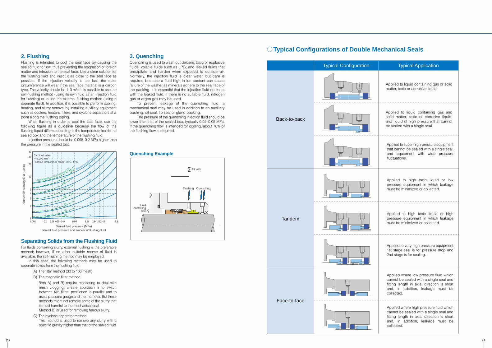
Back-to-back
Tandem
Face-to-face
Typical Configuration Typical Application
Applied to liquid containing gas or solid matter, toxic or corrosive liquid.
Applied to liquid containing gas and solid matter, toxic or corrosive liquid, and liquid of high pressure that cannot be sealed with a single seal.
Applied to super-high-pressure equipment that cannot be sealed with a single seal, and equipment with wide pressure fluctuations.
Applied to very high pressure equipment.1st stage seal is for pressure drop and 2nd stage is for sealing.
Applied where low pressure fluid which cannot be sealed with a single seal and fitting length in axial direction is short and, in addition, leakage must be collected.
Applied where high pressure fluid which cannot be sealed with a single seal and fitting length in axial direction is short and, in addition, leakage must be collected.
Applied to high toxic liquid or high pressure equipment in which leakage must be minimized or collected.
Applied to high toxic liquid or low pressure equipment in which leakage must be minimized or collected.
Am
ount
of f
lush
ing
flui
d (
L/m
in)
Sealed fluid pressure (MPa)Sealed fluid pressure and amount of flushing fluid
Carbide/carbonn=3,000 min-1
Flushing temperature range: 30°C–40°C
Unbalanced type Shaft diameter 150
Unbalanced type Shaft diameter 150 Balanced type Shaft d
iameter 150
Balanced type Shaft diameter 15
0
Fluidcontacting
side
Typical Configurations of Double Mechanical Seals
25 26
51 54
52 61
53A 62
53B 65
53C
Orifice
Strainer
Cooler
Stop valve
Check valve
Flow regulator
Relief valve
Flowmeter
Cyclone separator
Thermometer
Pressure gauge
Pressure switch
Upper limit pressure switch
Lower limit pressure switch
Upper level switch
Lower level switch
Bladder accumulator
Piston accumulator
Drain pot
Reservoir
Q/DF
F
PI PSH
LSHLSL
F
PI
TI
PSL
F
PI
TI
PSL
LSL
F
Q/DF
Q/DF
DFLSH
F
PI PSL
LSHLSL
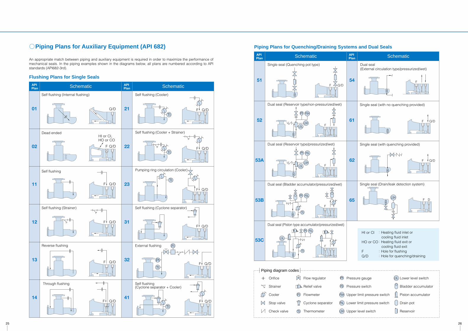
Piping diagram codes
API Plan Schematic API
Plan Schematic
HI or CI
HO or CO
FQ/D
: Heating fluid inlet or cooling fluid inlet: Heating fluid exit or cooling fluid exit: Hole for flushing : Hole for quenching/draining
Piping Plans for Auxiliary Equipment (API 682)
Flushing Plans for Single Seals
An appropriate match between piping and auxiliary equipment is required in order to maximize the performance of mechanical seals. In the piping examples shown in the diagrams below, all plans are numbered according to API standards (API682-3rd).
Self flushing (Internal flushing) Self flushing (Cooler)
Single seal (Quenching pot type)
Single seal (with no quenching provided)
Single seal (with quenching provided)
Single seal (Drain/leak detection system)
Dual seal (Reservoir type/non-pressurized/wet)
Dual seal (Reservoir type/pressurized/wet)
Dual seal (Bladder accumulator/pressurized/wet)
Dual seal (Piston type accumulator/pressurized/wet)
Dual seal(External circulation type/pressurized/wet)
Pumping ring circulation (Cooler)
Self flushing (Cooler + Strainer)
Self flushing (Strainer) Self flushing (Cyclone separator)
Self flushing(Cyclone separator + Cooler)
External flushingReverse flushing
Self flushing
Dead ended
Piping Plans for Quenching/Draining Systems and Dual Seals
01
Schematic
21
02 22
11 23
12 31
13 32
Through flushing
14 41
API Plan
API Plan Schematic
Q/D
Q/D
HI or CI,HO or CO
F
Q/DF
Q/DF
Q/DF
Q/DF
Q/DFTI
Q/DFTI
Q/DF
TI
Q/DF
Q/DFTI
PI
FI
Q/DFTI