Embed Size (px)
Citation preview
DOE Fundamentals
MECHANICAL SCIENCE
Module 3
Pumps
Mechanical Science Pumps
ME-03-ii
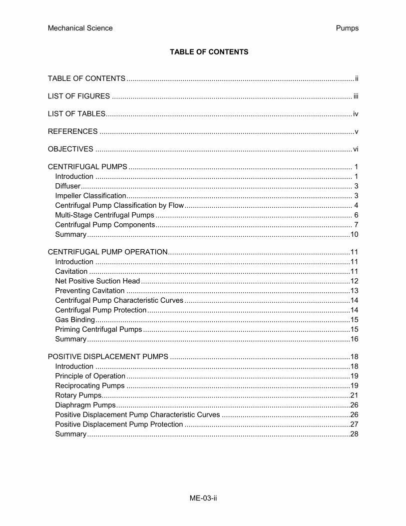
TABLE OF CONTENTS
TABLE OF CONTENTS .............................................................................................................. ii
LIST OF FIGURES .................................................................................................................... iii
LIST OF TABLES ....................................................................................................................... iv
REFERENCES ........................................................................................................................... v
OBJECTIVES ............................................................................................................................ vi
CENTRIFUGAL PUMPS ............................................................................................................ 1
Introduction ............................................................................................................................ 1
Diffuser ................................................................................................................................... 3
Impeller Classification ............................................................................................................. 3
Centrifugal Pump Classification by Flow ................................................................................. 4
Multi-Stage Centrifugal Pumps ............................................................................................... 6
Centrifugal Pump Components ............................................................................................... 7
Summary ...............................................................................................................................10
CENTRIFUGAL PUMP OPERATION ........................................................................................11
Introduction ...........................................................................................................................11
Cavitation ..............................................................................................................................11
Net Positive Suction Head .....................................................................................................12
Preventing Cavitation ............................................................................................................13
Centrifugal Pump Characteristic Curves ................................................................................14
Centrifugal Pump Protection ..................................................................................................14
Gas Binding ...........................................................................................................................15
Priming Centrifugal Pumps ....................................................................................................15
Summary ...............................................................................................................................16
POSITIVE DISPLACEMENT PUMPS .......................................................................................18
Introduction ...........................................................................................................................18
Principle of Operation ............................................................................................................19
Reciprocating Pumps ............................................................................................................19
Rotary Pumps ........................................................................................................................21
Diaphragm Pumps .................................................................................................................26
Positive Displacement Pump Characteristic Curves ..............................................................26
Positive Displacement Pump Protection ................................................................................27
Summary ...............................................................................................................................28
Mechanical Science Pumps
ME-03-iii
LIST OF FIGURES
Figure 1 Centrifugal Pump ..................................................................................................... 2
Figure 2 Single and Double Volutes ....................................................................................... 2
Figure 3 Centrifugal Pump Diffuser ........................................................................................ 3
Figure 4 Single Suction and Double Suction Impellers ........................................................... 3
Figure 5 Open, Semi-Open, and Enclosed Impellers .............................................................. 4
Figure 6 Radial Flow Centrifugal Pump .................................................................................. 5
Figure 7 Axial Flow Centrifugal Pump .................................................................................... 5
Figure 8 Mixed Flow Centrifugal Pump .................................................................................. 6
Figure 9 Multi-Stage Centrifugal Pump .................................................................................. 7
Figure 10 Centrifugal Pump Components .............................................................................. 8
Figure 11 Centrifugal Pump Characteristic Curve ................................................................ 14
Figure 12 Reciprocating Positive Displacement Pump Operation ......................................... 19
Figure 13 Single-Acting and Double-Acting Pumps .............................................................. 20
Figure 14 Simple Gear Pump ............................................................................................... 22
Figure 15 Types of Gears Used In Pumps ........................................................................... 23
Figure 16 Lobe Type Pump .................................................................................................. 23
Figure 17 Two-Screw, Low-Pitch, Screw Pump .................................................................... 24
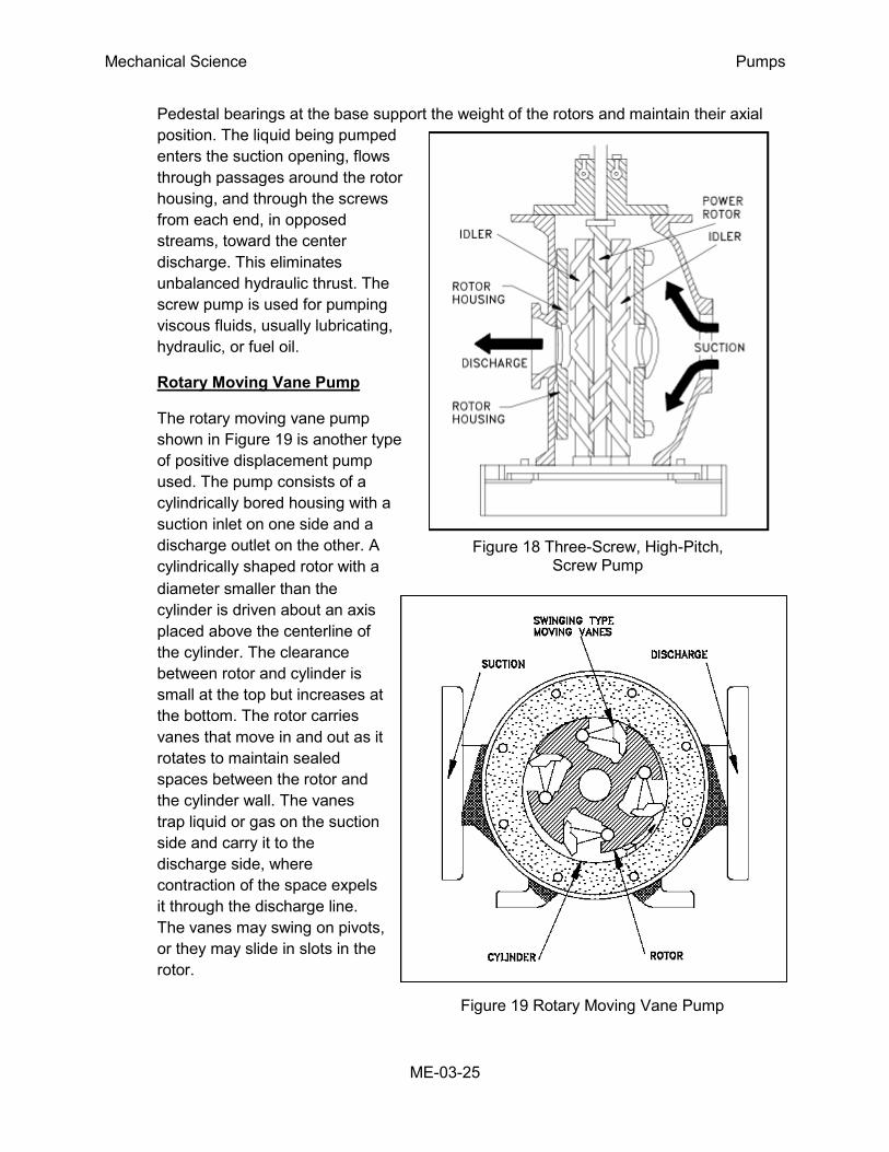
Figure 18 Three-Screw, High-Pitch, Screw Pump ................................................................ 25
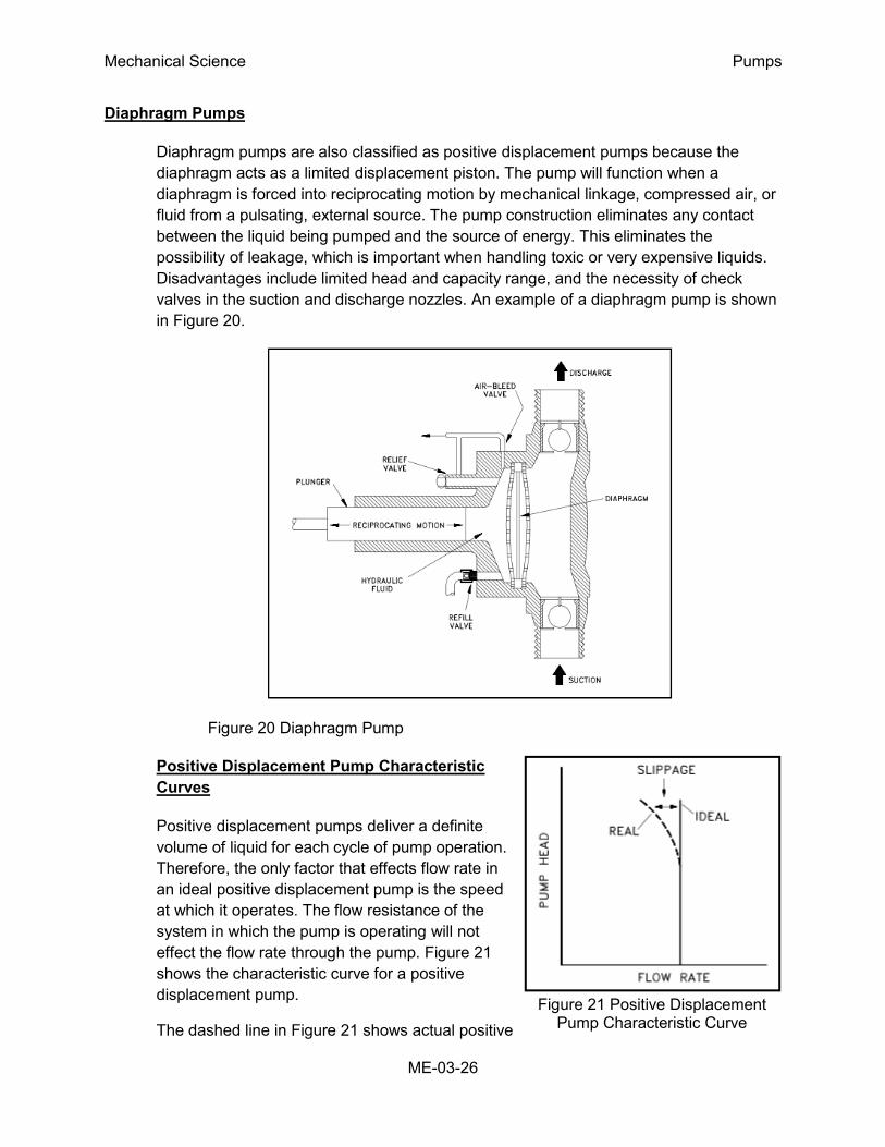
Figure 19 Rotary Moving Vane Pump .................................................................................. 25
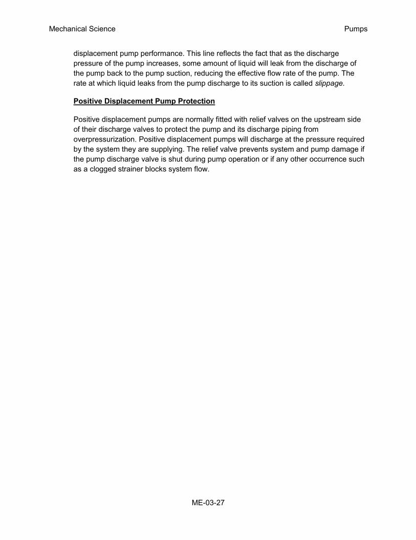
Figure 20 Diaphragm Pump ................................................................................................. 26
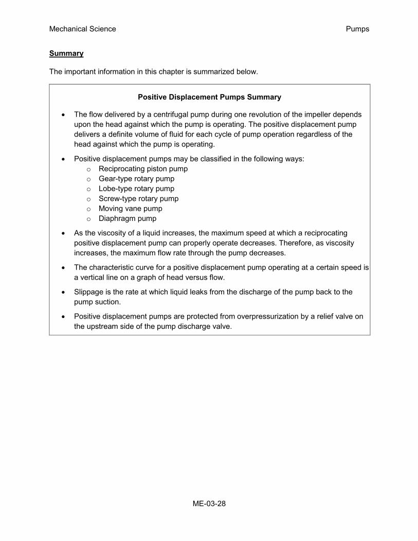
Figure 21 Positive Displacement Pump Characteristic Curve ............................................... 26

Mechanical Science Pumps
ME-03-iv
LIST OF TABLES
None
Mechanical Science Pumps
ME-03-v
REFERENCES
Babcock & Wilcox, Steam, Its Generations and Use 41st Edition, Babcock &
Wilcox Co.
Cheremisinoff, N. P., Fluid Flow, Pumps, Pipes and Channels, Ann Arbor
Science.
General Physics, Heat Transfer, Thermodynamics and Fluid Flow Fundamentals,
General Physics Corporation.
General Physics, Academic Program for Nuclear Power Plant Personnel, Volume
III, General Physics Corporation.
Stewart, Harry L., Pneumatics & Hydraulics, Theodore Audel & Company
.
Mechanical Science Pumps
ME-03-vi
OBJECTIVES
TERMINAL OBJECTIVE
1.0 Without references, DESCRIBE the purpose, construction, and principles of operation
for centrifugal pumps.
ENABLING OBJECTIVES
1.1 STATE the purposes of the following centrifugal pump components:
a. Impeller d. Packing
b. Volute e. Lantern Ring
c. Diffuser f. Wearing ring
1.2 Given a drawing of a centrifugal pump, IDENTIFY the following major components:
a. Pump casing f. Stuffing box gland
b. Pump shaft g. Packing
c. Impeller h. Lantern Ring
d. Volute i. Impeller wearing ring
e. Stuffing box j. Pump casing wearing ring
1.3 DEFINE the following terms:
a. Net Positive Suction Head Available d. Shutoff head
b. Cavitation e. Pump runout
c. Gas binding
1.4 STATE the relationship between net positive suction head available and net positive
suction head required that is necessary to avoid cavitation.
1.5 LIST three indications that a centrifugal pump may be cavitating.
1.6 LIST five changes that can be made in a pump or its surrounding system that can
reduce cavitation.
1.7 LIST three effects of cavitation.
1.8 DESCRIBE the shape of the characteristic curve for a centrifugal pump.
1.9 DESCRIBE how centrifugal pumps are protected from the conditions of dead heading
and pump runout.
Mechanical Science Pumps
ME-03-vii
TERMINAL OBJECTIVE
2.0 Without references, DESCRIBE the purpose, construction, and principle of operation for
positive displacement pumps.
ENABLING OBJECTIVES
2.1 STATE the difference between the flow characteristics of centrifugal and positive
displacement pumps.
2.2 Given a simplified drawing of a positive displacement pump, CLASSIFY the pump as
one of the following:
a. Reciprocating piston pump
b. Gear-type rotary pump
c. Screw-type rotary pump
d. Lobe-type rotary pump
e. Moving vane pump
f. Diaphragm pump
2.3 EXPLAIN the importance of viscosity as it relates to the operation of a reciprocating
positive displacement pump.
2.4 DESCRIBE the characteristic curve for a positive displacement pump.
2.5 DEFINE the term slippage.
2.6 STATE how positive displacement pumps are protected against overpressurization.
Mechanical Science Pumps
ME-03-1
CENTRIFUGAL PUMPS
Centrifugal pumps are the most common type of pumps found in DOE facilities.
Centrifugal pumps enjoy widespread application partly due to their ability to
operate over a wide range of flow rates and pump heads.
EO 1.1 STATE the purposes of the following centrifugal pump components:
a. Impeller d. Packing
b. Volute e. Lantern Ring
c. Diffuser f. Wearing ring
EO 1.2 Given a drawing of a centrifugal pump, IDENTIFY the following major
components:
a. Pump casing f. Stuffing box gland
b. Pump shaft g. Packing
c. Impeller h. Lantern Ring
d. Volute i. Impeller wearing ring
e. Stuffing box j. Pump casing wearing ring
Introduction
Centrifugal pumps basically consist of a stationary pump casing and an impeller mounted on a
rotating shaft. The pump casing provides a pressure boundary for the pump and contains
channels to properly direct the suction and discharge flow. The pump casing has suction and
discharge penetrations for the main flow path of the pump and normally has small drain and
vent fittings to remove gases trapped in the pump casing or to drain the pump casing for
maintenance.
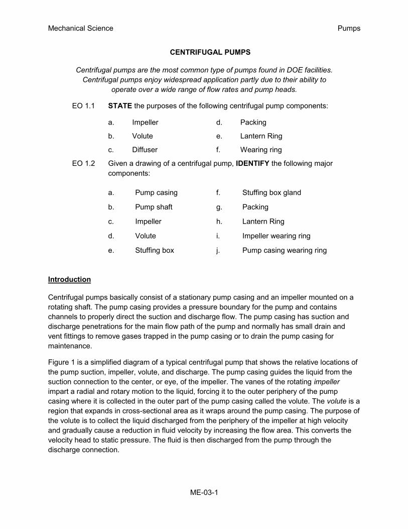
Figure 1 is a simplified diagram of a typical centrifugal pump that shows the relative locations of
the pump suction, impeller, volute, and discharge. The pump casing guides the liquid from the
suction connection to the center, or eye, of the impeller. The vanes of the rotating impeller
impart a radial and rotary motion to the liquid, forcing it to the outer periphery of the pump
casing where it is collected in the outer part of the pump casing called the volute. The volute is a
region that expands in cross-sectional area as it wraps around the pump casing. The purpose of
the volute is to collect the liquid discharged from the periphery of the impeller at high velocity
and gradually cause a reduction in fluid velocity by increasing the flow area. This converts the
velocity head to static pressure. The fluid is then discharged from the pump through the
discharge connection.
Mechanical Science Pumps
ME-03-2
Figure 1 Centrifugal Pump
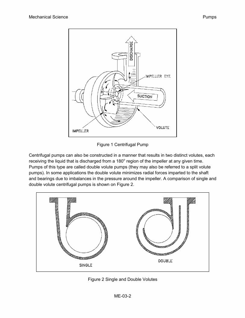
Centrifugal pumps can also be constructed in a manner that results in two distinct volutes, each
receiving the liquid that is discharged from a 180o region of the impeller at any given time.
Pumps of this type are called double volute pumps (they may also be referred to a split volute
pumps). In some applications the double volute minimizes radial forces imparted to the shaft
and bearings due to imbalances in the pressure around the impeller. A comparison of single and
double volute centrifugal pumps is shown on Figure 2.
Figure 2 Single and Double Volutes
Mechanical Science Pumps
ME-03-3
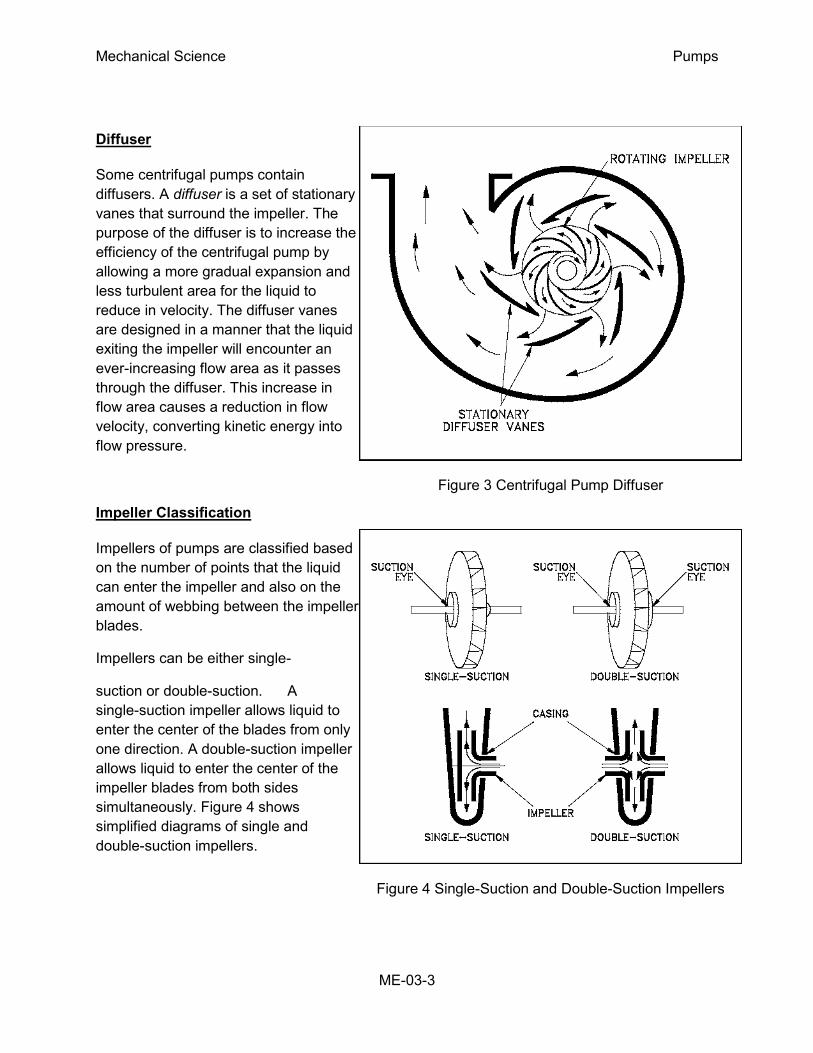
Figure 3 Centrifugal Pump Diffuser
Figure 4 Single-Suction and Double-Suction Impellers
Diffuser
Some centrifugal pumps contain
diffusers. A diffuser is a set of stationary
vanes that surround the impeller. The
purpose of the diffuser is to increase the
efficiency of the centrifugal pump by
allowing a more gradual expansion and
less turbulent area for the liquid to
reduce in velocity. The diffuser vanes
are designed in a manner that the liquid
exiting the impeller will encounter an
ever-increasing flow area as it passes
through the diffuser. This increase in
flow area causes a reduction in flow
velocity, converting kinetic energy into
flow pressure.
Impeller Classification
Impellers of pumps are classified based
on the number of points that the liquid
can enter the impeller and also on the
amount of webbing between the impeller
blades.
Impellers can be either single-
suction or double-suction. A
single-suction impeller allows liquid to
enter the center of the blades from only
one direction. A double-suction impeller
allows liquid to enter the center of the
impeller blades from both sides
simultaneously. Figure 4 shows
simplified diagrams of single and
double-suction impellers.
Mechanical Science Pumps
ME-03-4
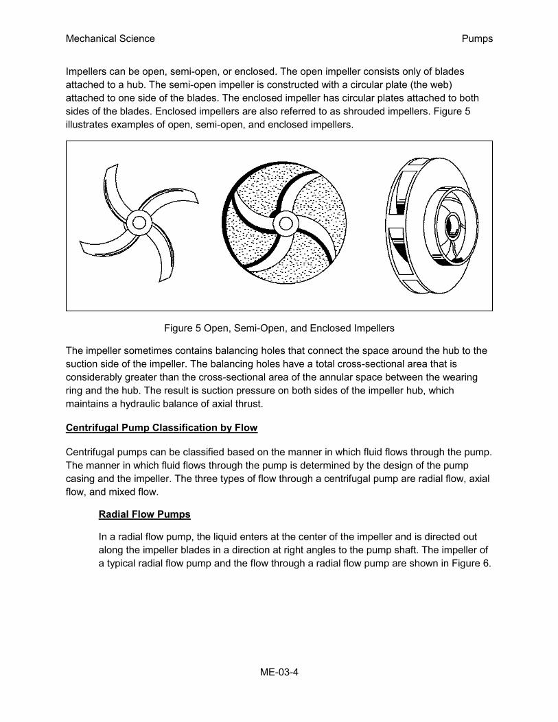
Impellers can be open, semi-open, or enclosed. The open impeller consists only of blades
attached to a hub. The semi-open impeller is constructed with a circular plate (the web)
attached to one side of the blades. The enclosed impeller has circular plates attached to both
sides of the blades. Enclosed impellers are also referred to as shrouded impellers. Figure 5
illustrates examples of open, semi-open, and enclosed impellers.
Figure 5 Open, Semi-Open, and Enclosed Impellers
The impeller sometimes contains balancing holes that connect the space around the hub to the
suction side of the impeller. The balancing holes have a total cross-sectional area that is
considerably greater than the cross-sectional area of the annular space between the wearing
ring and the hub. The result is suction pressure on both sides of the impeller hub, which
maintains a hydraulic balance of axial thrust.
Centrifugal Pump Classification by Flow
Centrifugal pumps can be classified based on the manner in which fluid flows through the pump.
The manner in which fluid flows through the pump is determined by the design of the pump
casing and the impeller. The three types of flow through a centrifugal pump are radial flow, axial
flow, and mixed flow.
Radial Flow Pumps
In a radial flow pump, the liquid enters at the center of the impeller and is directed out
along the impeller blades in a direction at right angles to the pump shaft. The impeller of
a typical radial flow pump and the flow through a radial flow pump are shown in Figure 6.
Mechanical Science Pumps
ME-03-5
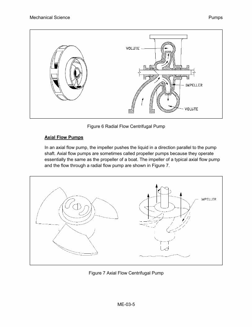
Figure 6 Radial Flow Centrifugal Pump
Axial Flow Pumps
In an axial flow pump, the impeller pushes the liquid in a direction parallel to the pump
shaft. Axial flow pumps are sometimes called propeller pumps because they operate
essentially the same as the propeller of a boat. The impeller of a typical axial flow pump
and the flow through a radial flow pump are shown in Figure 7.
Figure 7 Axial Flow Centrifugal Pump
Mechanical Science Pumps
ME-03-6
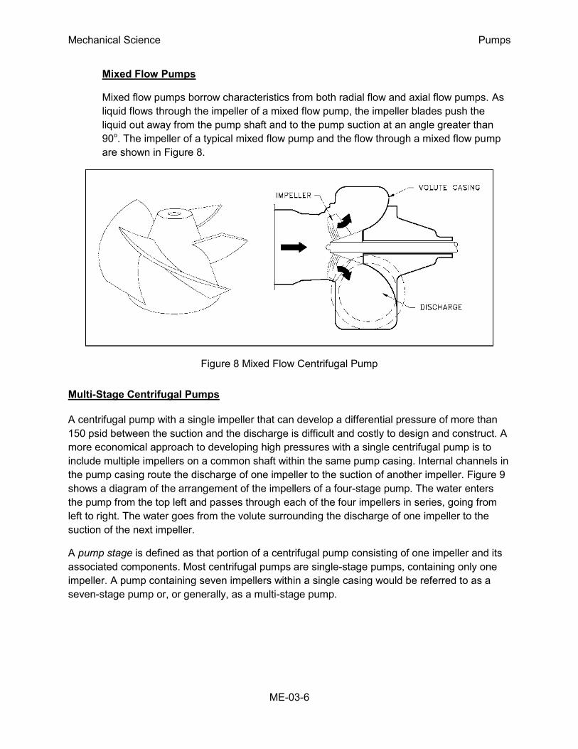
Mixed Flow Pumps
Mixed flow pumps borrow characteristics from both radial flow and axial flow pumps. As
liquid flows through the impeller of a mixed flow pump, the impeller blades push the
liquid out away from the pump shaft and to the pump suction at an angle greater than
90o. The impeller of a typical mixed flow pump and the flow through a mixed flow pump
are shown in Figure 8.
Figure 8 Mixed Flow Centrifugal Pump
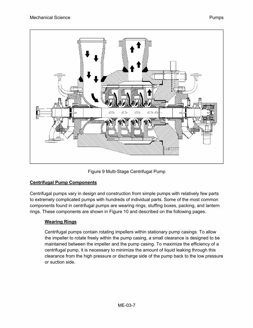
Multi-Stage Centrifugal Pumps
A centrifugal pump with a single impeller that can develop a differential pressure of more than
150 psid between the suction and the discharge is difficult and costly to design and construct. A
more economical approach to developing high pressures with a single centrifugal pump is to
include multiple impellers on a common shaft within the same pump casing. Internal channels in
the pump casing route the discharge of one impeller to the suction of another impeller. Figure 9
shows a diagram of the arrangement of the impellers of a four-stage pump. The water enters
the pump from the top left and passes through each of the four impellers in series, going from
left to right. The water goes from the volute surrounding the discharge of one impeller to the
suction of the next impeller.
A pump stage is defined as that portion of a centrifugal pump consisting of one impeller and its
associated components. Most centrifugal pumps are single-stage pumps, containing only one
impeller. A pump containing seven impellers within a single casing would be referred to as a
seven-stage pump or, or generally, as a multi-stage pump.
Mechanical Science Pumps
ME-03-7
Figure 9 Multi-Stage Centrifugal Pump
Centrifugal Pump Components
Centrifugal pumps vary in design and construction from simple pumps with relatively few parts
to extremely complicated pumps with hundreds of individual parts. Some of the most common
components found in centrifugal pumps are wearing rings, stuffing boxes, packing, and lantern
rings. These components are shown in Figure 10 and described on the following pages.
Wearing Rings
Centrifugal pumps contain rotating impellers within stationary pump casings. To allow
the impeller to rotate freely within the pump casing, a small clearance is designed to be
maintained between the impeller and the pump casing. To maximize the efficiency of a
centrifugal pump, it is necessary to minimize the amount of liquid leaking through this
clearance from the high pressure or discharge side of the pump back to the low pressure
or suction side.
Mechanical Science Pumps
ME-03-8
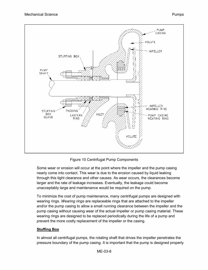
Figure 10 Centrifugal Pump Components
Some wear or erosion will occur at the point where the impeller and the pump casing
nearly come into contact. This wear is due to the erosion caused by liquid leaking
through this tight clearance and other causes. As wear occurs, the clearances become
larger and the rate of leakage increases. Eventually, the leakage could become
unacceptably large and maintenance would be required on the pump.
To minimize the cost of pump maintenance, many centrifugal pumps are designed with
wearing rings. Wearing rings are replaceable rings that are attached to the impeller
and/or the pump casing to allow a small running clearance between the impeller and the
pump casing without causing wear of the actual impeller or pump casing material. These
wearing rings are designed to be replaced periodically during the life of a pump and
prevent the more costly replacement of the impeller or the casing.
Stuffing Box
In almost all centrifugal pumps, the rotating shaft that drives the impeller penetrates the
pressure boundary of the pump casing. It is important that the pump is designed properly
Mechanical Science Pumps
ME-03-9
to control the amount of liquid that leaks along the shaft at the point that the shaft
penetrates the pump casing. There are many different methods of sealing the shaft
penetration of the pump casing. Factors considered when choosing a method include
the pressure and temperature of the fluid being pumped, the size of the pump, and the
chemical and physical characteristics of the fluid being pumped.
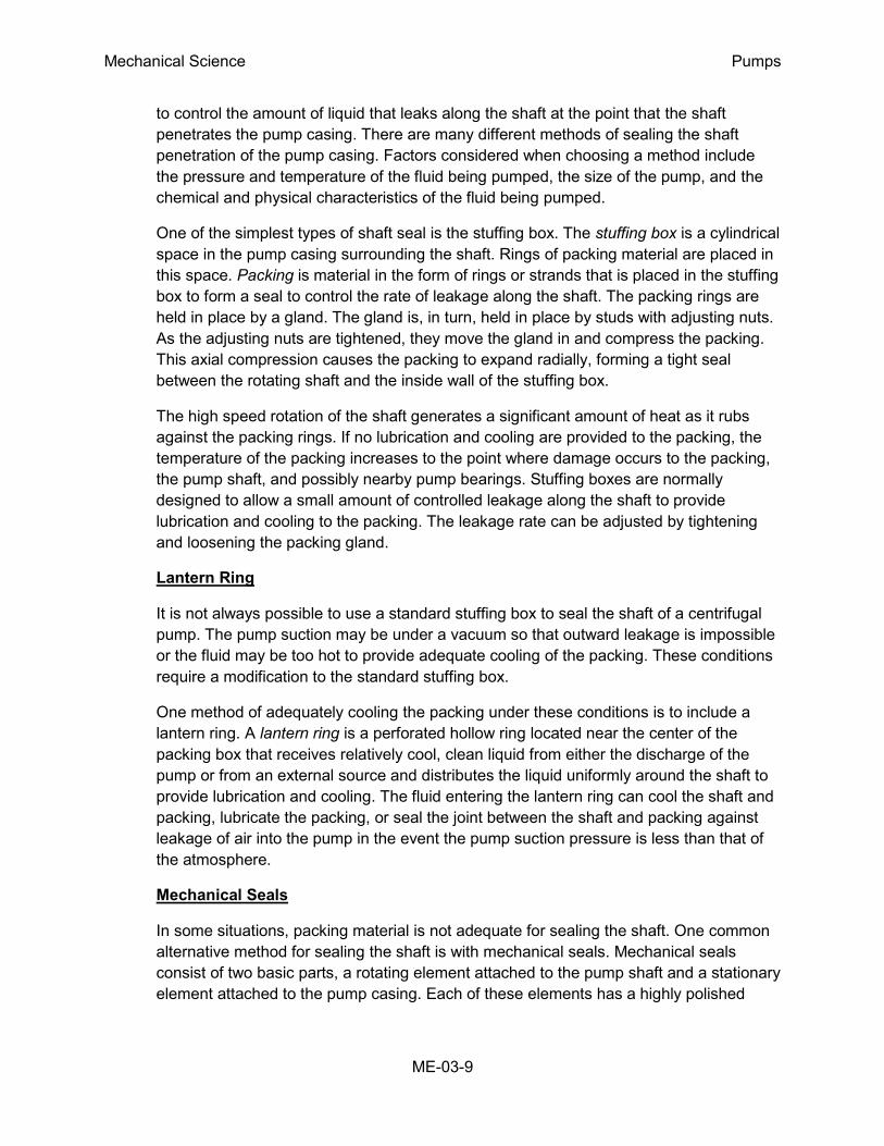
One of the simplest types of shaft seal is the stuffing box. The stuffing box is a cylindrical
space in the pump casing surrounding the shaft. Rings of packing material are placed in
this space. Packing is material in the form of rings or strands that is placed in the stuffing
box to form a seal to control the rate of leakage along the shaft. The packing rings are
held in place by a gland. The gland is, in turn, held in place by studs with adjusting nuts.
As the adjusting nuts are tightened, they move the gland in and compress the packing.
This axial compression causes the packing to expand radially, forming a tight seal
between the rotating shaft and the inside wall of the stuffing box.
The high speed rotation of the shaft generates a significant amount of heat as it rubs
against the packing rings. If no lubrication and cooling are provided to the packing, the
temperature of the packing increases to the point where damage occurs to the packing,
the pump shaft, and possibly nearby pump bearings. Stuffing boxes are normally
designed to allow a small amount of controlled leakage along the shaft to provide
lubrication and cooling to the packing. The leakage rate can be adjusted by tightening
and loosening the packing gland.
Lantern Ring
It is not always possible to use a standard stuffing box to seal the shaft of a centrifugal
pump. The pump suction may be under a vacuum so that outward leakage is impossible
or the fluid may be too hot to provide adequate cooling of the packing. These conditions
require a modification to the standard stuffing box.
One method of adequately cooling the packing under these conditions is to include a
lantern ring. A lantern ring is a perforated hollow ring located near the center of the
packing box that receives relatively cool, clean liquid from either the discharge of the
pump or from an external source and distributes the liquid uniformly around the shaft to
provide lubrication and cooling. The fluid entering the lantern ring can cool the shaft and
packing, lubricate the packing, or seal the joint between the shaft and packing against
leakage of air into the pump in the event the pump suction pressure is less than that of
the atmosphere.
Mechanical Seals
In some situations, packing material is not adequate for sealing the shaft. One common
alternative method for sealing the shaft is with mechanical seals. Mechanical seals
consist of two basic parts, a rotating element attached to the pump shaft and a stationary
element attached to the pump casing. Each of these elements has a highly polished
Mechanical Science Pumps
ME-03-10
sealing surface. The polished faces of the rotating and stationary elements come into
contact with each other to form a seal that prevents leakage along the shaft.
Summary
The important information in this chapter is summarized below.
Centrifugal Pumps Summary
The impeller contains rotating vanes that impart a radial and rotary motion to the liquid.
The volute collects the liquid discharged from the impeller at high velocity and gradually
causes a reduction in fluid velocity by increasing the flow area, converting the velocity
head to a static head.
A diffuser increases the efficiency of a centrifugal pump by allowing a more gradual
expansion and less turbulent area for the liquid to slow as the flow area expands.
Packing material provides a seal in the area where the pump shaft penetrates the pump
casing.
Wearing rings are replaceable rings that are attached to the impeller and/or the pump
casing to allow a small running clearance between the impeller and pump casing without
causing wear of the actual impeller or pump casing material.
The lantern ring is inserted between rings of packing in the stuffing box to receive
relatively cool, clean liquid and distribute the liquid uniformly around the shaft to provide
lubrication and cooling to the packing.
Mechanical Science Pumps
ME-03-11
CENTRIFUGAL PUMP OPERATION
Improper operation of centrifugal pumps can result in damage to the pump and
loss of function of the system that the pump is installed in. It is helpful to know
what conditions can lead to pump damage to allow better understanding of pump
operating procedures and how the procedures aid the operator in avoiding pump
damage.
EO 1.3 DEFINE the following terms:
a. Net Positive Suction c. Gas binding
b. Head Available d. Shutoff head
c. Cavitation e. Pump runout
EO 1.4 STATE the relationship between net positive suction head available and net
positive suction head required that is necessary to avoid cavitation.
EO 1.5 LIST three indications that a centrifugal pump may be cavitating.
EO 1.6 LIST five changes that can be made in a pump or its surrounding system that
can reduce cavitation.
EO 1.7 LIST three effects of cavitation.
EO 1.8 DESCRIBE the shape of the characteristic curve for a centrifugal pump.
EO 1.9 DESCRIBE how centrifugal pumps are protected from the conditions of dead
heading and pump runout.
Introduction
Many centrifugal pumps are designed in a manner that allows the pump to operate continuously
for months or even years. These centrifugal pumps often rely on the liquid that they are
pumping to provide cooling and lubrication to the pump bearings and other internal components
of the pump. If flow through the pump is stopped while the pump is still operating, the pump will
no longer be adequately cooled and the pump can quickly become damaged. Pump damage
can also result from pumping a liquid whose temperature is close to saturated conditions.
Cavitation
The flow area at the eye of the pump impeller is usually smaller than either the flow area of the
pump suction piping or the flow area through the impeller vanes. When the liquid being pumped
enters the eye of a centrifugal pump, the decrease in flow area results in an increase in flow
velocity accompanied by a decrease in pressure. The greater the pump flow rate, the greater
the pressure drop between the pump suction and the eye of the impeller. If the pressure drop is
large enough, or if the temperature is high enough, the pressure drop may be sufficient to cause
the liquid to flash to vapor when the local pressure falls below the saturation pressure for the
Mechanical Science Pumps
ME-03-12
fluid being pumped. Any vapor bubbles formed by the pressure drop at the eye of the impeller
are swept along the impeller vanes by the flow of the fluid. When the bubbles enter a region
where local pressure is greater than saturation pressure farther out the impeller vane, the vapor
bubbles abruptly collapse. This process of the formation and subsequent collapse of vapor
bubbles in a pump is called cavitation.
Cavitation in a centrifugal pump has a significant effect on pump performance. Cavitation
degrades the performance of a pump, resulting in a fluctuating flow rate and discharge
pressure. Cavitation can also be destructive to pumps internal components. When a pump
cavitates, vapor bubbles form in the low pressure region directly behind the rotating impeller
vanes. These vapor bubbles then move toward the oncoming impeller vane, where they
collapse and cause a physical shock to the leading edge of the impeller vane. This physical
shock creates small pits on the leading edge of the impeller vane. Each individual pit is
microscopic in size, but the cumulative effect of millions of these pits formed over a period of
hours or days can literally destroy a pump impeller. Cavitation can also cause excessive pump
vibration, which could damage pump bearings, wearing rings, and seals.
A small number of centrifugal pumps are designed to operate under conditions where cavitation
is unavoidable. These pumps must be specially designed and maintained to withstand the small
amount of cavitation that occurs during their operation. Most centrifugal pumps are not designed
to withstand sustained cavitation.
Noise is one of the indications that a centrifugal pump is cavitating. A cavitating pump can
sound like a can of marbles being shaken. Other indications that can be observed from a
remote operating station are fluctuating discharge pressure, flow rate, and pump motor current.
Methods to stop or prevent cavitation are presented in the following paragraphs.
Net Positive Suction Head
To avoid cavitation in centrifugal pumps, the pressure of the fluid at all points within the pump
must remain above saturation pressure. The quantity used to determine if the pressure of the
liquid being pumped is adequate to avoid cavitation is the net positive suction head (NPSH).
The net positive suction head available (NPSHA) is the difference between the pressure at the
suction of the pump and the saturation pressure for the liquid being pumped. The net positive
suction head required (NPSHR) is the minimum net positive suction head necessary to avoid
cavitation.
The condition that must exist to avoid cavitation is that the net positive suction head available
must be greater than or equal to the net positive suction head required. This requirement can be
stated mathematically as shown below.
NPSHA ≥ NPSHR
A formula for NPSHA can be stated as the following equation.
NPSHA = Psuction - Psaturation
Mechanical Science Pumps
ME-03-13
When a centrifugal pump is taking suction from a tank or other reservoir, the pressure at the
suction of the pump is the sum of the absolute pressure at the surface of the liquid in the tank
plus the pressure due to the elevation difference between the surface of liquid in the tank and
the pump suction less the head losses due to friction in the suction line from the tank to the
pump.
NPSHA = Pa + Pst - hf - Psat
Where:
NPSHA = net positive suction head available
Pa = absolute pressure on the surface of the liquid
Pst = pressure due to elevation between liquid surface and pump suction
hf = head losses in the pump suction piping
Psat = saturation pressure of the liquid being pumped
Preventing Cavitation
If a centrifugal pump is cavitating, several changes in the system design or operation may be
necessary to increase the NPSHA above the NPSHR and stop the cavitation. One method for
increasing the NPSHA is to increase the pressure at the suction of the pump. For example, if a
pump is taking suction from an enclosed tank, either raising the level of the liquid in the tank or
increasing the pressure in the space above the liquid increases suction pressure.
It is also possible to increase the NPSHA by decreasing the temperature of the liquid being
pumped. Decreasing the temperature of the liquid decreases the saturation pressure, causing
NPSHA to increase. Recall from the previous module on heat exchangers that large steam
condensers usually subcool the condensate to less than the saturation temperature, called
condensate depression, to prevent cavitation in the condensate pumps.
If the head losses in the pump suction piping can be reduced, the NPSHA will be increased.
Various methods for reducing head losses include increasing the pipe diameter, reducing the
number of elbows, valves, and fittings in the pipe, and decreasing the length of the pipe.
It may also be possible to stop cavitation by reducing the NPSHR for the pump. The NPSHR is
not a constant for a given pump under all conditions, but depends on certain factors. Typically,
the NPSHR of a pump increases significantly as flow rate through the pump increases.
Therefore, reducing the flow rate through a pump by throttling a discharge valve decreases
NPSHR. NPSHR is also dependent upon pump speed. The faster the impeller of a pump rotates,
the greater the NPSHR. Therefore, if the speed of a variable speed centrifugal pump is reduced,
the NPSHR of the pump decreases. However, since a pump's flow rate is most often dictated by
the needs of the system on which it is connected, only limited adjustments can be made without
starting additional parallel pumps, if available.
Mechanical Science Pumps
ME-03-14
The net positive suction head required to prevent cavitation is determined through testing by the
pump manufacturer and depends upon factors including type of impeller inlet, impeller design,
pump flow rate, impeller rotational speed, and the type of liquid being pumped. The
manufacturer typically supplies curves of NPSHR as a function of pump flow rate for a particular
liquid (usually water) in the vendor manual for the pump.
Centrifugal Pump Characteristic Curves
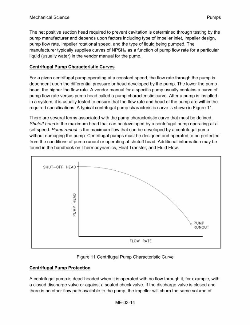
For a given centrifugal pump operating at a constant speed, the flow rate through the pump is
dependent upon the differential pressure or head developed by the pump. The lower the pump
head, the higher the flow rate. A vendor manual for a specific pump usually contains a curve of
pump flow rate versus pump head called a pump characteristic curve. After a pump is installed
in a system, it is usually tested to ensure that the flow rate and head of the pump are within the
required specifications. A typical centrifugal pump characteristic curve is shown in Figure 11.
There are several terms associated with the pump characteristic curve that must be defined.
Shutoff head is the maximum head that can be developed by a centrifugal pump operating at a
set speed. Pump runout is the maximum flow that can be developed by a centrifugal pump
without damaging the pump. Centrifugal pumps must be designed and operated to be protected
from the conditions of pump runout or operating at shutoff head. Additional information may be
found in the handbook on Thermodynamics, Heat Transfer, and Fluid Flow.
Figure 11 Centrifugal Pump Characteristic Curve
Centrifugal Pump Protection
A centrifugal pump is dead-headed when it is operated with no flow through it, for example, with
a closed discharge valve or against a seated check valve. If the discharge valve is closed and
there is no other flow path available to the pump, the impeller will churn the same volume of
Mechanical Science Pumps
ME-03-15
water as it rotates in the pump casing. This will increase the temperature of the liquid (due to
friction) in the pump casing to the point that it will flash to vapor. The vapor can interrupt the
cooling flow to the pump's packing and bearings, causing excessive wear and heat. If the pump
is run in this condition for a significant amount of time, it will become damaged.
When a centrifugal pump is installed in a system such that it may be subjected to periodic
shutoff head conditions, it is necessary to provide some means of pump protection. One method
for protecting the pump from running dead-headed is to provide a recirculation line from the
pump discharge line upstream of the discharge valve, back to the pump's supply source. The
recirculation line should be sized to allow enough flow through the pump to prevent overheating
and damage to the pump. Protection may also be accomplished by use of an automatic flow
control device.
Centrifugal pumps must also be protected from runout. Runout can lead to cavitation and can
also cause overheating of the pump's motor due to excessive currents. One method for
ensuring that there is always adequate flow resistance at the pump discharge to prevent
excessive flow through the pump is to place an orifice or a throttle valve immediately
downstream of the pump discharge. Properly designed piping systems are very important to
protect from runout.
Gas Binding
Gas binding of a centrifugal pump is a condition where the pump casing is filled with gases or
vapors to the point where the impeller is no longer able to contact enough fluid to function
correctly. The impeller spins in the gas bubble, but is unable to force liquid through the pump.
This can lead to cooling problems for the pump's packing and bearings.
Centrifugal pumps are designed so that their pump casings are completely filled with liquid
during pump operation. Most centrifugal pumps can still operate when a small amount of gas
accumulates in the pump casing, but pumps in systems containing dissolved gases that are not
designed to be self-venting should be periodically vented manually to ensure that gases do not
build up in the pump casing.
Priming Centrifugal Pumps
Most centrifugal pumps are not self-priming. In other words, the pump casing must be filled with
liquid before the pump is started, or the pump will not be able to function. If the pump casing
becomes filled with vapors or gases, the pump impeller becomes gas-bound and incapable of
pumping. To ensure that a centrifugal pump remains primed and does not become gas-bound,
most centrifugal pumps are located below the level of the source from which the pump is to take
its suction. The same effect can be gained by supplying liquid to the pump suction under
pressure supplied by another pump placed in the suction line.
Mechanical Science Pumps
ME-03-16
Summary
The important information in this chapter is summarized below.
Centrifugal Pump Operation Summary
There are three indications that a centrifugal pump is cavitating.
o Noise
o Fluctuating discharge pressure and flow
o Fluctuating pump motor current
Steps that can be taken to stop pump cavitation include:
o Increase the pressure at the suction of the pump.
o Reduce the temperature of the liquid being pumped.
o Reduce head losses in the pump suction piping.
o Reduce the flow rate through the pump.
o Reduce the speed of the pump impeller.
Three effects of pump cavitation are:
o Degraded pump performance
o Excessive pump vibration
o Damage to pump impeller, bearings, wearing rings, and seals
To avoid pump cavitation, the net positive suction head available must be greater than
the net positive suction head required.
Net positive suction head available is the difference between the pump suction
pressure and the saturation pressure for the liquid being pumped.
Cavitation is the process of the formation and subsequent collapse of vapor bubbles in
a pump.
Gas binding of a centrifugal pump is a condition where the pump casing is filled with
gases or vapors to the point where the impeller is no longer able to contact enough
fluid to function correctly.
Shutoff head is the maximum head that can be developed by a centrifugal pump
operating at a set speed.
Mechanical Science Pumps
ME-03-17
Centrifugal Pump Operation Summary (Cont.)
Pump runout is the maximum flow that can be developed by a centrifugal pump without
damaging the pump.
The greater the head against which a centrifugal pump operates, the lower the flow rate
through the pump. The relationship between pump flow rate and head is illustrated by
the characteristic curve for the pump.
Centrifugal pumps are protected from dead-heading by providing a recirculation from the
pump discharge back to the supply source of the pump.
Centrifugal pumps are protected from runout by placing an orifice or throttle valve
immediately downstream of the pump discharge and through proper piping system
design.
Mechanical Science Pumps
ME-03-18
POSITIVE DISPLACEMENT PUMPS
Positive displacement pumps operate on a different principle than centrifugal
pumps. Positive displacement pumps physically entrap a quantity of liquid at the
suction of the pump and push that quantity out the discharge of the pump.
EO 2.1 STATE the difference between the flow characteristics of centrifugal and
positive displacement pumps.
EO 2.2 Given a simplified drawing of a positive displacement pump, CLASSIFY the
pump as one of the following:
a. Reciprocating piston pump e. Moving vane pump
b. Gear-type rotary pump f. Diaphragm pump
c. Screw-type rotary pump
d. Lobe-type rotary pump
EO 2.3 EXPLAIN the importance of viscosity as it relates to the operation of a
reciprocating positive displacement pump.
EO 2.4 DESCRIBE the characteristic curve for a positive displacement pump.
EO 2.5 DEFINE the term slippage.
EO 2.6 STATE how positive displacement pumps are protected against
overpressurization.
Introduction
A positive displacement pump is one in which a definite volume of liquid is delivered for each
cycle of pump operation. This volume is constant regardless of the resistance to flow offered by
the system the pump is in, provided the capacity of the power unit driving the pump or pump
component strength limits are not exceeded. The positive displacement pump delivers liquid in
separate volumes with no delivery in between, although a pump having several chambers may
have an overlapping delivery among individual chambers, which minimizes this effect. The
positive displacement pump differs from centrifugal pumps, which deliver a continuous flow for
any given pump speed and discharge resistance.
Positive displacement pumps can be grouped into three basic categories based on their design
and operation. The three groups are reciprocating pumps, rotary pumps, and diaphragm pumps.
Mechanical Science Pumps
ME-03-19
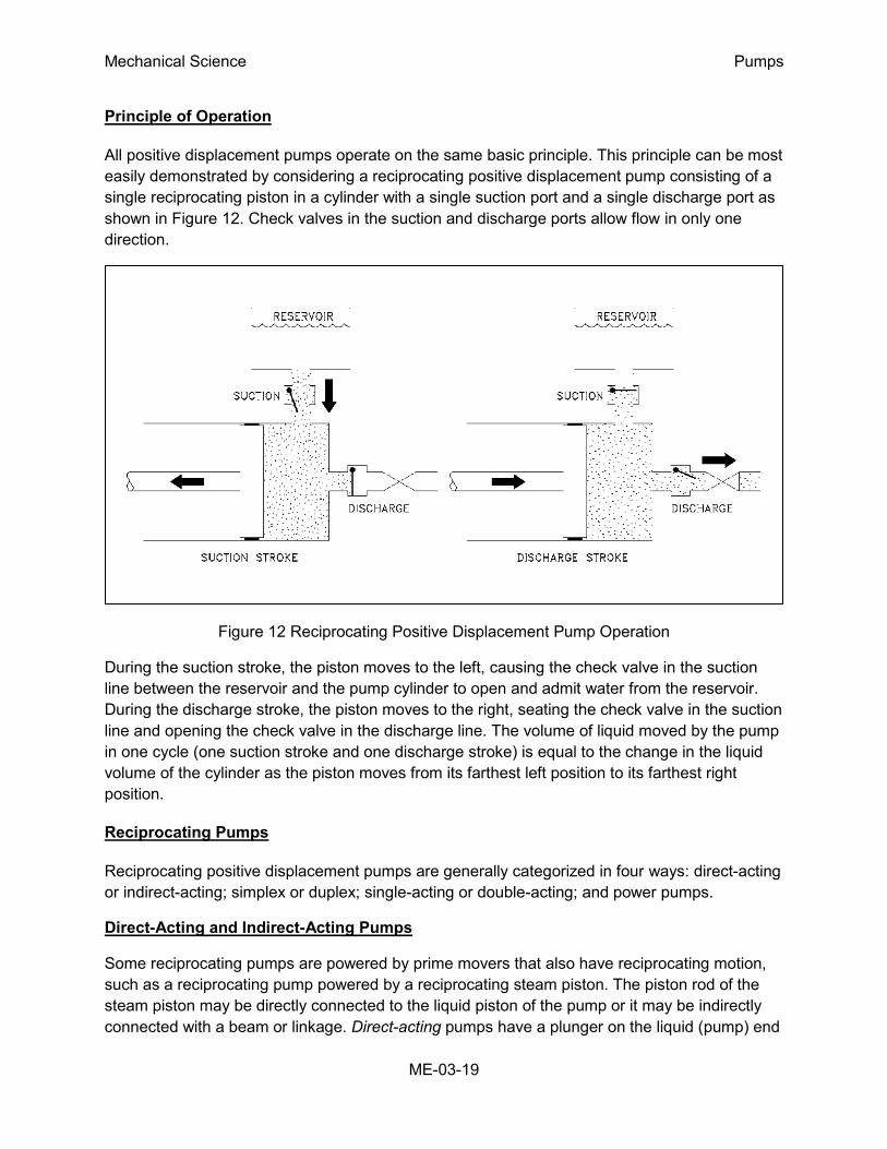
Principle of Operation
All positive displacement pumps operate on the same basic principle. This principle can be most
easily demonstrated by considering a reciprocating positive displacement pump consisting of a
single reciprocating piston in a cylinder with a single suction port and a single discharge port as
shown in Figure 12. Check valves in the suction and discharge ports allow flow in only one
direction.
Figure 12 Reciprocating Positive Displacement Pump Operation
During the suction stroke, the piston moves to the left, causing the check valve in the suction
line between the reservoir and the pump cylinder to open and admit water from the reservoir.
During the discharge stroke, the piston moves to the right, seating the check valve in the suction
line and opening the check valve in the discharge line. The volume of liquid moved by the pump
in one cycle (one suction stroke and one discharge stroke) is equal to the change in the liquid
volume of the cylinder as the piston moves from its farthest left position to its farthest right
position.
Reciprocating Pumps
Reciprocating positive displacement pumps are generally categorized in four ways: direct-acting
or indirect-acting; simplex or duplex; single-acting or double-acting; and power pumps.
Direct-Acting and Indirect-Acting Pumps
Some reciprocating pumps are powered by prime movers that also have reciprocating motion,
such as a reciprocating pump powered by a reciprocating steam piston. The piston rod of the
steam piston may be directly connected to the liquid piston of the pump or it may be indirectly
connected with a beam or linkage. Direct-acting pumps have a plunger on the liquid (pump) end
Mechanical Science Pumps
ME-03-20
that is directly driven by the pump rod (also the piston rod or extension thereof) and carries the
piston of the power end. Indirect-acting pumps are driven by means of a beam or linkage
connected to and actuated by the power piston rod of a separate reciprocating engine.
Simplex and Duplex Pumps
A simplex pump, sometimes referred to as a single pump, is a pump having a single liquid
(pump) cylinder. A duplex pump is the equivalent of two simplex pumps placed side by side on
the same foundation.
The driving of the pistons of a duplex pump is arranged in such a manner that when one piston
is on its upstroke the other piston is on its downstroke, and vice versa. This arrangement
doubles the capacity of the duplex pump compared to a simplex pump of comparable design.
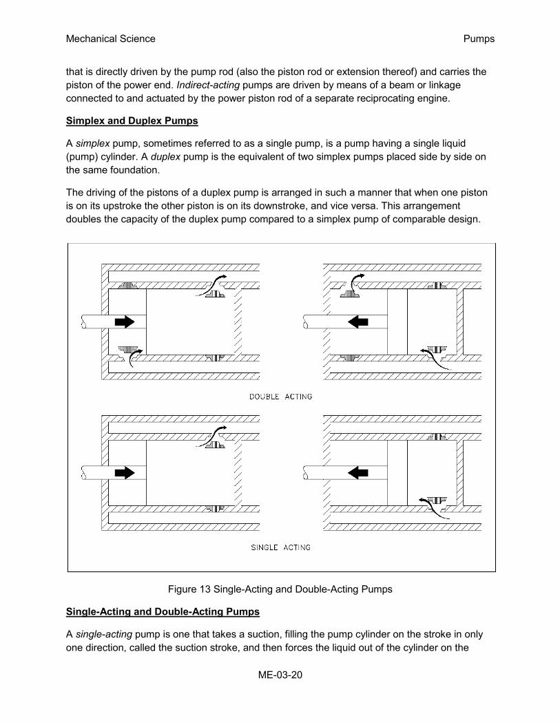
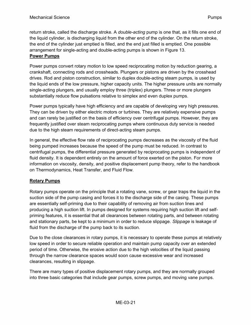
Figure 13 Single-Acting and Double-Acting Pumps
Single-Acting and Double-Acting Pumps
A single-acting pump is one that takes a suction, filling the pump cylinder on the stroke in only
one direction, called the suction stroke, and then forces the liquid out of the cylinder on the
Mechanical Science Pumps
ME-03-21
return stroke, called the discharge stroke. A double-acting pump is one that, as it fills one end of
the liquid cylinder, is discharging liquid from the other end of the cylinder. On the return stroke,
the end of the cylinder just emptied is filled, and the end just filled is emptied. One possible
arrangement for single-acting and double-acting pumps is shown in Figure 13.
Power Pumps
Power pumps convert rotary motion to low speed reciprocating motion by reduction gearing, a
crankshaft, connecting rods and crossheads. Plungers or pistons are driven by the crosshead
drives. Rod and piston construction, similar to duplex double-acting steam pumps, is used by
the liquid ends of the low pressure, higher capacity units. The higher pressure units are normally
single-acting plungers, and usually employ three (triplex) plungers. Three or more plungers
substantially reduce flow pulsations relative to simplex and even duplex pumps.
Power pumps typically have high efficiency and are capable of developing very high pressures.
They can be driven by either electric motors or turbines. They are relatively expensive pumps
and can rarely be justified on the basis of efficiency over centrifugal pumps. However, they are
frequently justified over steam reciprocating pumps where continuous duty service is needed
due to the high steam requirements of direct-acting steam pumps.
In general, the effective flow rate of reciprocating pumps decreases as the viscosity of the fluid
being pumped increases because the speed of the pump must be reduced. In contrast to
centrifugal pumps, the differential pressure generated by reciprocating pumps is independent of
fluid density. It is dependent entirely on the amount of force exerted on the piston. For more
information on viscosity, density, and positive displacement pump theory, refer to the handbook
on Thermodynamics, Heat Transfer, and Fluid Flow.
Rotary Pumps
Rotary pumps operate on the principle that a rotating vane, screw, or gear traps the liquid in the
suction side of the pump casing and forces it to the discharge side of the casing. These pumps
are essentially self-priming due to their capability of removing air from suction lines and
producing a high suction lift. In pumps designed for systems requiring high suction lift and self-
priming features, it is essential that all clearances between rotating parts, and between rotating
and stationary parts, be kept to a minimum in order to reduce slippage. Slippage is leakage of
fluid from the discharge of the pump back to its suction.
Due to the close clearances in rotary pumps, it is necessary to operate these pumps at relatively
low speed in order to secure reliable operation and maintain pump capacity over an extended
period of time. Otherwise, the erosive action due to the high velocities of the liquid passing
through the narrow clearance spaces would soon cause excessive wear and increased
clearances, resulting in slippage.
There are many types of positive displacement rotary pumps, and they are normally grouped
into three basic categories that include gear pumps, screw pumps, and moving vane pumps.
Mechanical Science Pumps
ME-03-22
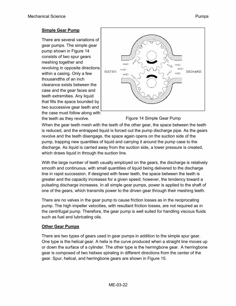
Simple Gear Pump
There are several variations of
gear pumps. The simple gear
pump shown in Figure 14
consists of two spur gears
meshing together and
revolving in opposite directions
within a casing. Only a few
thousandths of an inch
clearance exists between the
case and the gear faces and
teeth extremities. Any liquid
that fills the space bounded by
two successive gear teeth and
the case must follow along with
the teeth as they revolve.
Figure 14 Simple Gear Pump
When the gear teeth mesh with the teeth of the other gear, the space between the teeth
is reduced, and the entrapped liquid is forced out the pump discharge pipe. As the gears
revolve and the teeth disengage, the space again opens on the suction side of the
pump, trapping new quantities of liquid and carrying it around the pump case to the
discharge. As liquid is carried away from the suction side, a lower pressure is created,
which draws liquid in through the suction line.
With the large number of teeth usually employed on the gears, the discharge is relatively
smooth and continuous, with small quantities of liquid being delivered to the discharge
line in rapid succession. If designed with fewer teeth, the space between the teeth is
greater and the capacity increases for a given speed; however, the tendency toward a
pulsating discharge increases. In all simple gear pumps, power is applied to the shaft of
one of the gears, which transmits power to the driven gear through their meshing teeth.
There are no valves in the gear pump to cause friction losses as in the reciprocating
pump. The high impeller velocities, with resultant friction losses, are not required as in
the centrifugal pump. Therefore, the gear pump is well suited for handling viscous fluids
such as fuel and lubricating oils.
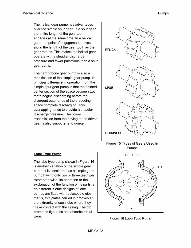
Other Gear Pumps
There are two types of gears used in gear pumps in addition to the simple spur gear.
One type is the helical gear. A helix is the curve produced when a straight line moves up
or down the surface of a cylinder. The other type is the herringbone gear. A herringbone
gear is composed of two helixes spiraling in different directions from the center of the
gear. Spur, helical, and herringbone gears are shown in Figure 15.
Mechanical Science Pumps
ME-03-23
Figure 15 Types of Gears Used In
Pumps
The helical gear pump has advantages
over the simple spur gear. In a spur gear,
the entire length of the gear tooth
engages at the same time. In a helical
gear, the point of engagement moves
along the length of the gear tooth as the
gear rotates. This makes the helical gear
operate with a steadier discharge
pressure and fewer pulsations than a spur
gear pump.
The herringbone gear pump is also a
modification of the simple gear pump. Its
principal difference in operation from the
simple spur gear pump is that the pointed
center section of the space between two
teeth begins discharging before the
divergent outer ends of the preceding
space complete discharging. This
overlapping tends to provide a steadier
discharge pressure. The power
transmission from the driving to the driven
gear is also smoother and quieter.
Lobe Type Pump
The lobe type pump shown in Figure 16
is another variation of the simple gear
pump. It is considered as a simple gear
pump having only two or three teeth per
rotor; otherwise, its operation or the
explanation of the function of its parts is
no different. Some designs of lobe
pumps are fitted with replaceable gibs,
that is, thin plates carried in grooves at
the extremity of each lobe where they
make contact with the casing. The gib
promotes tightness and absorbs radial
wear.
Figure 16 Lobe Type Pump
Mechanical Science Pumps
ME-03-24
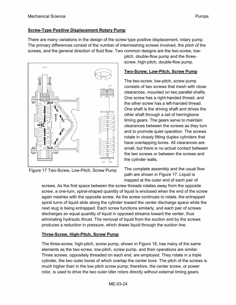
Figure 17 Two-Screw, Low-Pitch, Screw Pump
Screw-Type Positive Displacement Rotary Pump
There are many variations in the design of the screw type positive displacement, rotary pump.
The primary differences consist of the number of intermeshing screws involved, the pitch of the
screws, and the general direction of fluid flow. Two common designs are the two-screw, low-
pitch, double-flow pump and the three-
screw, high-pitch, double-flow pump.
Two-Screw, Low-Pitch, Screw Pump
The two-screw, low-pitch, screw pump
consists of two screws that mesh with close
clearances, mounted on two parallel shafts.
One screw has a right-handed thread, and
the other screw has a left-handed thread.
One shaft is the driving shaft and drives the
other shaft through a set of herringbone
timing gears. The gears serve to maintain
clearances between the screws as they turn
and to promote quiet operation. The screws
rotate in closely fitting duplex cylinders that
have overlapping bores. All clearances are
small, but there is no actual contact between
the two screws or between the screws and
the cylinder walls.
The complete assembly and the usual flow
path are shown in Figure 17. Liquid is
trapped at the outer end of each pair of
screws. As the first space between the screw threads rotates away from the opposite
screw, a one-turn, spiral-shaped quantity of liquid is enclosed when the end of the screw
again meshes with the opposite screw. As the screw continues to rotate, the entrapped
spiral turns of liquid slide along the cylinder toward the center discharge space while the
next slug is being entrapped. Each screw functions similarly, and each pair of screws
discharges an equal quantity of liquid in opposed streams toward the center, thus
eliminating hydraulic thrust. The removal of liquid from the suction end by the screws
produces a reduction in pressure, which draws liquid through the suction line.
Three-Screw, High-Pitch, Screw Pump
The three-screw, high-pitch, screw pump, shown in Figure 18, has many of the same
elements as the two-screw, low-pitch, screw pump, and their operations are similar.
Three screws, oppositely threaded on each end, are employed. They rotate in a triple
cylinder, the two outer bores of which overlap the center bore. The pitch of the screws is
much higher than in the low pitch screw pump; therefore, the center screw, or power
rotor, is used to drive the two outer idler rotors directly without external timing gears.
Mechanical Science Pumps
ME-03-25
Figure 18 Three-Screw, High-Pitch, Screw Pump
Pedestal bearings at the base support the weight of the rotors and maintain their axial
position. The liquid being pumped
enters the suction opening, flows
through passages around the rotor
housing, and through the screws
from each end, in opposed
streams, toward the center
discharge. This eliminates
unbalanced hydraulic thrust. The
screw pump is used for pumping
viscous fluids, usually lubricating,
hydraulic, or fuel oil.
Rotary Moving Vane Pump
The rotary moving vane pump
shown in Figure 19 is another type
of positive displacement pump
used. The pump consists of a
cylindrically bored housing with a
suction inlet on one side and a
discharge outlet on the other. A
cylindrically shaped rotor with a
diameter smaller than the
cylinder is driven about an axis
placed above the centerline of
the cylinder. The clearance
between rotor and cylinder is
small at the top but increases at
the bottom. The rotor carries
vanes that move in and out as it
rotates to maintain sealed
spaces between the rotor and
the cylinder wall. The vanes
trap liquid or gas on the suction
side and carry it to the
discharge side, where
contraction of the space expels
it through the discharge line.
The vanes may swing on pivots,
or they may slide in slots in the
rotor.
Figure 19 Rotary Moving Vane Pump
Mechanical Science Pumps
ME-03-26
Figure 21 Positive Displacement Pump Characteristic Curve
Diaphragm Pumps
Diaphragm pumps are also classified as positive displacement pumps because the
diaphragm acts as a limited displacement piston. The pump will function when a
diaphragm is forced into reciprocating motion by mechanical linkage, compressed air, or
fluid from a pulsating, external source. The pump construction eliminates any contact
between the liquid being pumped and the source of energy. This eliminates the
possibility of leakage, which is important when handling toxic or very expensive liquids.
Disadvantages include limited head and capacity range, and the necessity of check
valves in the suction and discharge nozzles. An example of a diaphragm pump is shown
in Figure 20.
Figure 20 Diaphragm Pump
Positive Displacement Pump Characteristic
Curves
Positive displacement pumps deliver a definite
volume of liquid for each cycle of pump operation.
Therefore, the only factor that effects flow rate in
an ideal positive displacement pump is the speed
at which it operates. The flow resistance of the
system in which the pump is operating will not
effect the flow rate through the pump. Figure 21
shows the characteristic curve for a positive
displacement pump.
The dashed line in Figure 21 shows actual positive
Mechanical Science Pumps
ME-03-27
displacement pump performance. This line reflects the fact that as the discharge
pressure of the pump increases, some amount of liquid will leak from the discharge of
the pump back to the pump suction, reducing the effective flow rate of the pump. The
rate at which liquid leaks from the pump discharge to its suction is called slippage.
Positive Displacement Pump Protection
Positive displacement pumps are normally fitted with relief valves on the upstream side
of their discharge valves to protect the pump and its discharge piping from
overpressurization. Positive displacement pumps will discharge at the pressure required
by the system they are supplying. The relief valve prevents system and pump damage if
the pump discharge valve is shut during pump operation or if any other occurrence such
as a clogged strainer blocks system flow.
Mechanical Science Pumps
ME-03-28
Summary
The important information in this chapter is summarized below.
Positive Displacement Pumps Summary
The flow delivered by a centrifugal pump during one revolution of the impeller depends
upon the head against which the pump is operating. The positive displacement pump
delivers a definite volume of fluid for each cycle of pump operation regardless of the
head against which the pump is operating.
Positive displacement pumps may be classified in the following ways:
o Reciprocating piston pump
o Gear-type rotary pump
o Lobe-type rotary pump
o Screw-type rotary pump
o Moving vane pump
o Diaphragm pump
As the viscosity of a liquid increases, the maximum speed at which a reciprocating
positive displacement pump can properly operate decreases. Therefore, as viscosity
increases, the maximum flow rate through the pump decreases.
The characteristic curve for a positive displacement pump operating at a certain speed is
a vertical line on a graph of head versus flow.
Slippage is the rate at which liquid leaks from the discharge of the pump back to the
pump suction.
Positive displacement pumps are protected from overpressurization by a relief valve on
the upstream side of the pump discharge valve.