Embed Size (px)
Citation preview
Mechanical Response of Shells to Tube Rupture in
STHEsJOINT WEBINAR BY EI, SONG AND HTS – 28 APRIL 2021
COLIN DEDDIS, ALAN CLAYTON, ROB KULKA

Talk outline
� Context and Background
� Surge caused by tube rupture
� Shell response
� Effective pressure
� FE Validation
� Guidelines on relief device design
� Next Steps
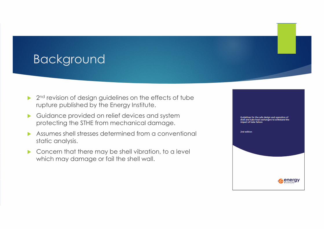
Background
� 2nd revision of design guidelines on the effects of tube rupture published by the Energy Institute.
� Guidance provided on relief devices and system protecting the STHE from mechanical damage.
� Assumes shell stresses determined from a conventional static analysis.
� Concern that there may be shell vibration, to a level which may damage or fail the shell wall.

Baseline Review
� Review of experience and methods used to determine the effects of tube failures
� Predominant mode of tube failure is leak-before–break.
� Circumstances of fully circ. tube rupture or longitudinal splitting may occur.
� Hydraulic analysis used to determine the pressure pulse from a tube rupture.
� Shell stress magnification caused by the dynamic effects of the pressure pulse
� Companies recognise the threat to shell integrity from dynamic effects but do not normally do dynamic structural analysis.
� Mitigation of the risk is provided by the pressure relief system, periodic in-service inspection of the tubes, and leak monitoring.

Process
� Pressure step at surge front Pis
Ruptured tube
Bubble of high pressure gas
Surge front
Calculation of surge pressure step
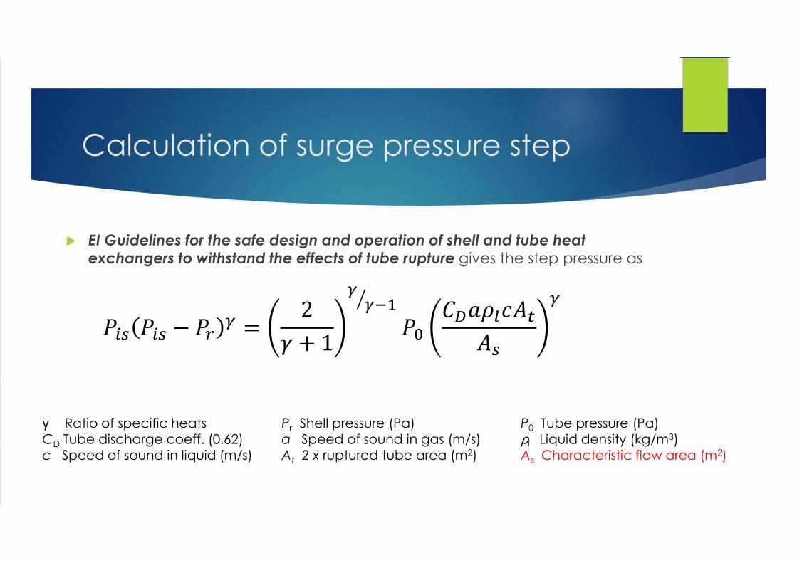
� EI Guidelines for the safe design and operation of shell and tube heat exchangers to withstand the effects of tube rupture gives the step pressure as
��� ��� � ��� �
2
1
��� �
����������
��
�
γ Ratio of specific heats Pr Shell pressure (Pa) P0 Tube pressure (Pa)
CD Tube discharge coeff. (0.62) a Speed of sound in gas (m/s) ρl Liquid density (kg/m3)c Speed of sound in liquid (m/s) At 2 x ruptured tube area (m2) As Characteristic flow area (m2)
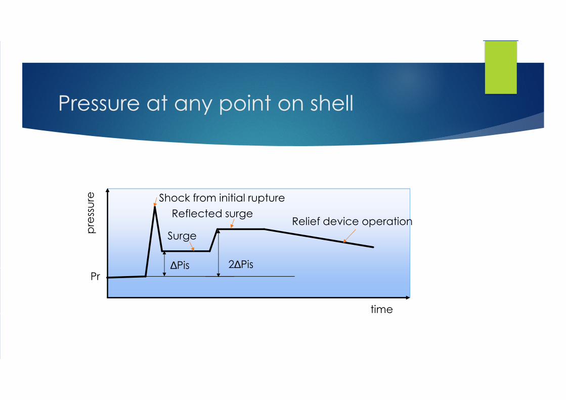
Pressure at any point on shell
Shock from initial rupture
Surge
Reflected surgeRelief device operation
pre
ssu
re
time
Pr∆Pis 2∆Pis
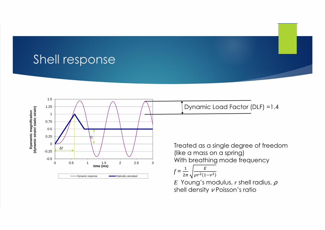
Shell response
-0.5
-0.25
0
0.25
0.5
0.75
1
1.25
1.5
0 0.5 1 1.5 2 2.5 3
Dya
nam
ic m
agn
ific
atio
n(d
ynam
ic s
trai
n/ s
tati
c st
rain
)
time (ms)
Dynamic response Statically calculated
∆t
q
Dynamic Load Factor (DLF) =1.4
Treated as a single degree of freedom (like a mass on a spring)With breathing mode frequency
f =
��
�
��� ����
E Young’s modulus, r shell radius, ρshell density ν Poisson’s ratio
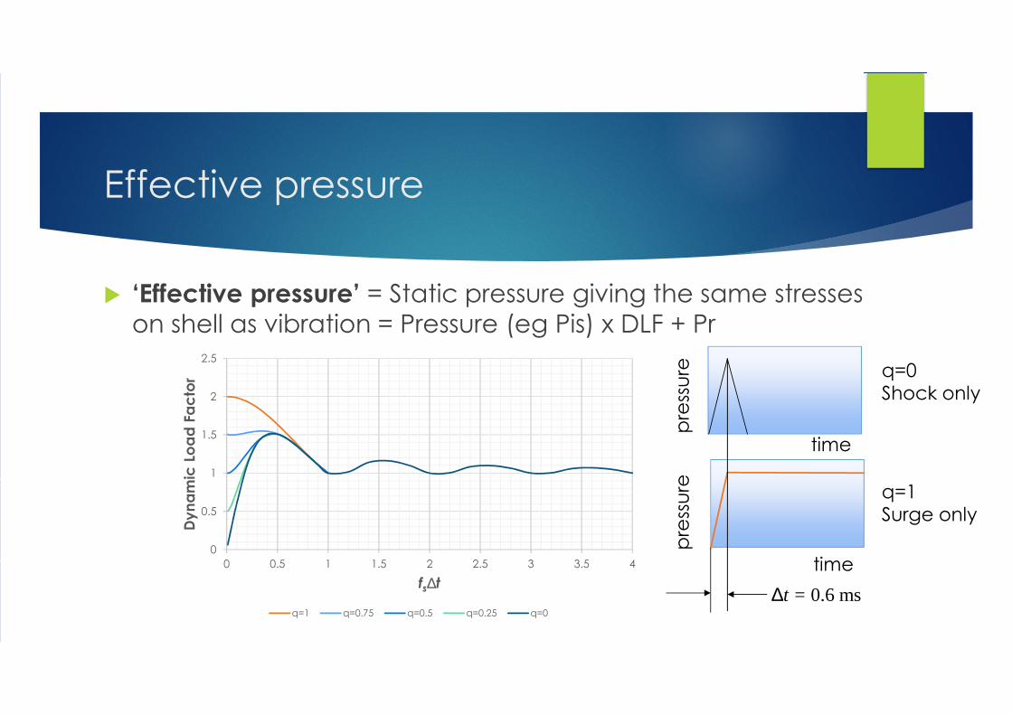
Effective pressure
� ‘Effective pressure’ = Static pressure giving the same stresses
on shell as vibration = Pressure (eg Pis) x DLF + Pr
0
0.5
1
1.5
2
2.5
0 0.5 1 1.5 2 2.5 3 3.5 4
Dy
na
mic
Lo
ad
Fa
cto
r
fs∆t
q=1 q=0.75 q=0.5 q=0.25 q=0
pre
ssu
rep
ress
ure
time
time
q=0Shock only
q=1Surge only
∆t = 0.6 ms
Validation of Approach using FEA
� Evaluation of the surge pressure variation with time, which is key to how the shell will respond. Two types of information are available:
� Tests carried out by the Health and Safety Laboratory (HSL) on an instrumented STHE.
� One-dimensional flow calculations by Hydraulic Analysis Ltd (HAL) on three typical STHEs of various sizes.
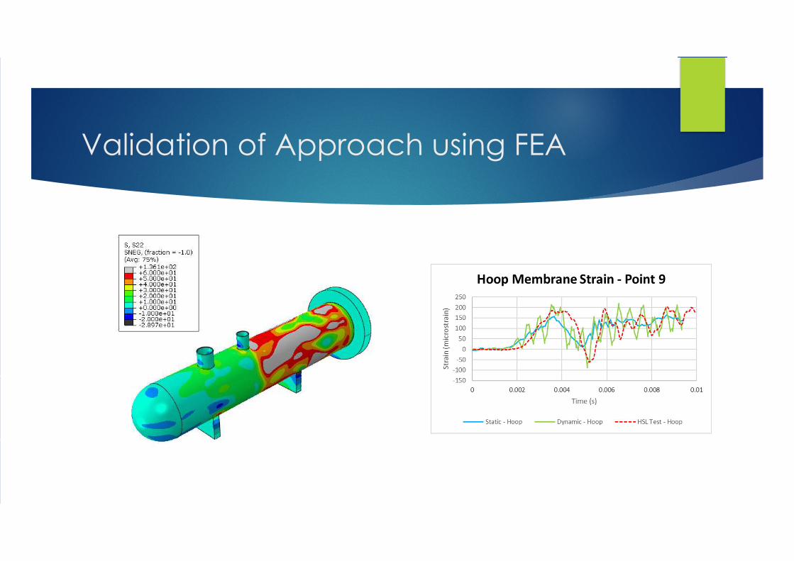
� Finite element (FE) models of the HSL test STHE were constructed. These were used to confirm that FE modelling could predict the strains measured with strain gauges on the test with reasonable accuracy.
� Further FE of the vessels analysed by HAL, representative of actual vessels, were then developed.
� Used to determine the full range of natural frequencies and their spectral response.
� Also determined the variation of stress in the shell wall with time and hence the DMF.

Validation of Approach using FEA
HSL Test Idealisation
Pressure Transient (from Measurements)
Predicted and Measured Response
Validation of Approach using FEA

Validation of Approach using FEA
small
medium largesmall

Validation of Approach using FEA
small
medium largesmall

Validation of Approach using FEA
Large STHE
Conclusions from the stress analysis
� Statically calculated surge stresses can be approximated by simple pressurised cylinder equations.
� Dynamic enhancement to the static stress caused by shell wall oscillating as the surge passes appears to be associated only with the breathing mode.
� Small and medium sized STHEs with radii in the range of typically 100mm to 500mm have insignificant dynamic magnification of the statically determined stresses.
� For larger heat exchangers, dynamic magnification of stresses is more significant.
� The duration of dynamic oscillations, is limited to a few cycles because of the damping of the fluid in the shell.
� Should the tube fail close to the shell there is the possibility of impulsive full tube pressure pulse impacting the wall which may result in high localised stresses.
Hydrotest and Relief device
� Tube rupture is very rare but potentially catastrophic
� For such events if maximum pressure = Hydrotest Pressure then possible permanent deformation but no failure
� So can set the calculated ‘effective pressure’ to be the hydrotest pressure
� Relief valves can cause reflection of surge but burst discs only cause very short shock which can be neglected
� Thus with relief valve, the hydrotest pressure > Pr + (2∆Pis)x DLF
� With burst discs (and no other immediate reflection) the hydrotest pressure> Pr + (∆Pis)x DLF

Example of relief design for tube
rupture
e.g. 1.3 x set pressure
Relief device required
Bursting disc required
Relief inadequate
‘Effective pressure’
Actual
pressure
Nominal relief valve
set pressure
Min acceptable Allowable Incident Pressure
Time after rupture
Pre
ssu
re
HP side design pressure
HP side operating pressure
Next Steps
� Revision of EI guidelines.
� Dissemination of information to industry codes and standards committees.