Embed Size (px)
Citation preview
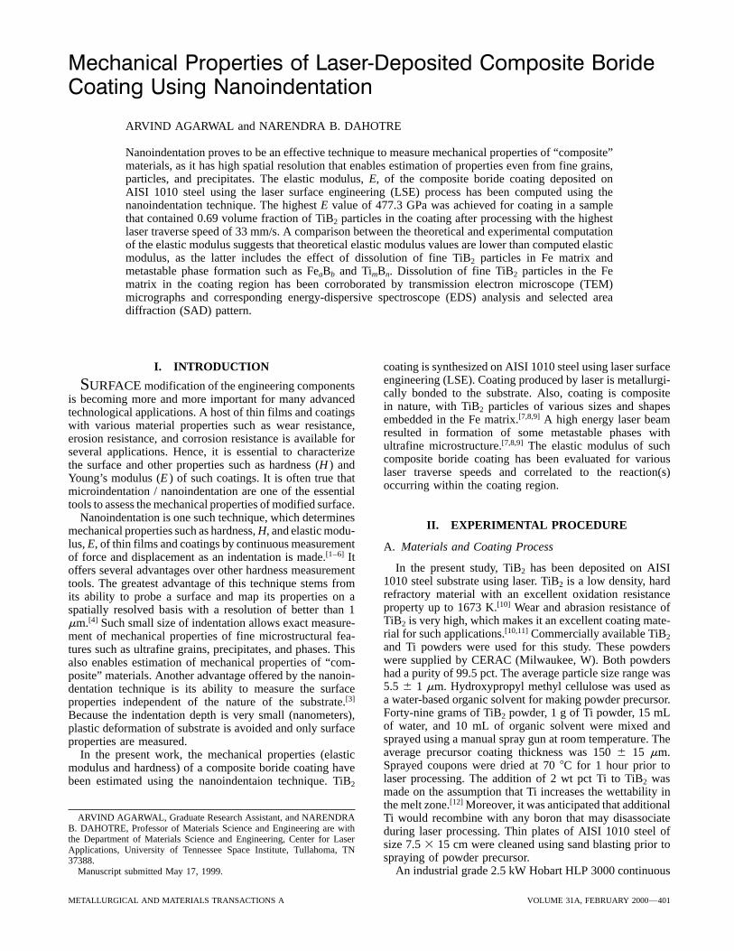
Mechanical Properties of Laser-Deposited Composite BorideCoating Using Nanoindentation
ARVIND AGARWAL and NARENDRA B. DAHOTRE
Nanoindentation proves to be an effective technique to measure mechanical properties of “composite”materials, as it has high spatial resolution that enables estimation of properties even from fine grains,particles, and precipitates. The elastic modulus, E, of the composite boride coating deposited onAISI 1010 steel using the laser surface engineering (LSE) process has been computed using thenanoindentation technique. The highest E value of 477.3 GPa was achieved for coating in a samplethat contained 0.69 volume fraction of TiB2 particles in the coating after processing with the highestlaser traverse speed of 33 mm/s. A comparison between the theoretical and experimental computationof the elastic modulus suggests that theoretical elastic modulus values are lower than computed elasticmodulus, as the latter includes the effect of dissolution of fine TiB2 particles in Fe matrix andmetastable phase formation such as FeaBb and TimBn. Dissolution of fine TiB2 particles in the Fematrix in the coating region has been corroborated by transmission electron microscope (TEM)micrographs and corresponding energy-dispersive spectroscope (EDS) analysis and selected areadiffraction (SAD) pattern.
I. INTRODUCTION coating is synthesized on AISI 1010 steel using laser surfaceengineering (LSE). Coating produced by laser is metallurgi-SURFACE modification of the engineering componentscally bonded to the substrate. Also, coating is compositeis becoming more and more important for many advancedin nature, with TiB2 particles of various sizes and shapestechnological applications. A host of thin films and coatingsembedded in the Fe matrix.[7,8,9] A high energy laser beamwith various material properties such as wear resistance,resulted in formation of some metastable phases witherosion resistance, and corrosion resistance is available forultrafine microstructure.[7,8,9] The elastic modulus of suchseveral applications. Hence, it is essential to characterizecomposite boride coating has been evaluated for variousthe surface and other properties such as hardness (H ) andlaser traverse speeds and correlated to the reaction(s)Young’s modulus (E ) of such coatings. It is often true thatoccurring within the coating region.microindentation / nanoindentation are one of the essential
tools to assess the mechanical properties of modified surface.Nanoindentation is one such technique, which determines
II. EXPERIMENTAL PROCEDUREmechanical properties such as hardness, H, and elastic modu-lus, E, of thin films and coatings by continuous measurement A. Materials and Coating Processof force and displacement as an indentation is made.[1–6] It
In the present study, TiB2 has been deposited on AISIoffers several advantages over other hardness measurement1010 steel substrate using laser. TiB2 is a low density, hardtools. The greatest advantage of this technique stems fromrefractory material with an excellent oxidation resistanceits ability to probe a surface and map its properties on aproperty up to 1673 K.[10] Wear and abrasion resistance ofspatially resolved basis with a resolution of better than 1TiB2 is very high, which makes it an excellent coating mate-mm.[4] Such small size of indentation allows exact measure-rial for such applications.[10,11] Commercially available TiB2ment of mechanical properties of fine microstructural fea-and Ti powders were used for this study. These powderstures such as ultrafine grains, precipitates, and phases. Thiswere supplied by CERAC (Milwaukee, W). Both powdersalso enables estimation of mechanical properties of “com-had a purity of 99.5 pct. The average particle size range wasposite” materials. Another advantage offered by the nanoin-5.5 6 1 mm. Hydroxypropyl methyl cellulose was used asdentation technique is its ability to measure the surfacea water-based organic solvent for making powder precursor.properties independent of the nature of the substrate.[3]
Forty-nine grams of TiB2 powder, 1 g of Ti powder, 15 mLBecause the indentation depth is very small (nanometers),of water, and 10 mL of organic solvent were mixed andplastic deformation of substrate is avoided and only surfacesprayed using a manual spray gun at room temperature. Theproperties are measured.average precursor coating thickness was 150 6 15 mm.In the present work, the mechanical properties (elasticSprayed coupons were dried at 70 8C for 1 hour prior tomodulus and hardness) of a composite boride coating havelaser processing. The addition of 2 wt pct Ti to TiB2 wasbeen estimated using the nanoindentaion technique. TiB2made on the assumption that Ti increases the wettability inthe melt zone.[12] Moreover, it was anticipated that additional
ARVIND AGARWAL, Graduate Research Assistant, and NARENDRA Ti would recombine with any boron that may disassociateB. DAHOTRE, Professor of Materials Science and Engineering are with during laser processing. Thin plates of AISI 1010 steel ofthe Department of Materials Science and Engineering, Center for Laser size 7.5 3 15 cm were cleaned using sand blasting prior toApplications, University of Tennessee Space Institute, Tullahoma, TN
spraying of powder precursor.37388.Manuscript submitted May 17, 1999. An industrial grade 2.5 kW Hobart HLP 3000 continuous
METALLURGICAL AND MATERIALS TRANSACTIONS A VOLUME 31A, FEBRUARY 2000—401
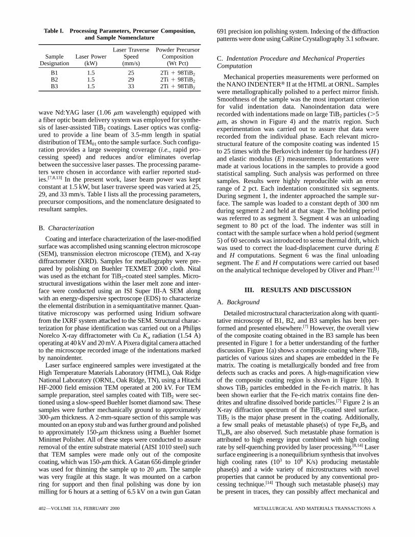
Table I. Processing Parameters, Precursor Composition, 691 precision ion polishing system. Indexing of the diffractionand Sample Nomenclature patterns were done using CaRine Crystallography 3.1 software.
Laser Traverse Powder PrecursorSample Laser Power Speed Composition C. Indentation Procedure and Mechanical Properties
Designation (kW) (mm/s) (Wt Pct) ComputationB1 1.5 25 2Ti 1 98TiB2 Mechanical properties measurements were performed onB2 1.5 29 2Ti 1 98TiB2
the NANO INDENTERT II at the HTML at ORNL. SamplesB3 1.5 33 2Ti 1 98TiB2were metallographically polished to a perfect mirror finish.Smoothness of the sample was the most important criterionfor valid indentation data. Nanoindentation data were
wave Nd:YAG laser (1.06 mm wavelength) equipped with recorded with indentations made on large TiB2 particles (.5a fiber optic beam delivery system was employed for synthe- mm, as shown in Figure 4) and the matrix region. Suchsis of laser-assisted TiB2 coatings. Laser optics was config- experimentation was carried out to assure that data wereured to provide a line beam of 3.5-mm length in spatial recorded from the individual phase. Each relevant micro-distribution of TEM01 onto the sample surface. Such configu- structural feature of the composite coating was indented 15ration provides a large sweeping coverage (i.e., rapid pro- to 25 times with the Berkovich indenter tip for hardness (H )cessing speed) and reduces and/or eliminates overlap and elastic modulus (E ) measurements. Indentations werebetween the successive laser passes. The processing parame- made at various locations in the samples to provide a goodters were chosen in accordance with earlier reported stud- statistical sampling. Such analysis was performed on threeies.[7,8,13] In the present work, laser beam power was kept samples. Results were highly reproducible with an errorconstant at 1.5 kW, but laser traverse speed was varied at 25, range of 2 pct. Each indentation constituted six segments.29, and 33 mm/s. Table I lists all the processing parameters, During segment 1, the indenter approached the sample sur-precursor compositions, and the nomenclature designated to face. The sample was loaded to a constant depth of 300 nmresultant samples. during segment 2 and held at that stage. The holding period
was referred to as segment 3. Segment 4 was an unloadingsegment to 80 pct of the load. The indenter was still inB. Characterizationcontact with the sample surface when a hold period (segment
Coating and interface characterization of the laser-modified 5) of 60 seconds was introduced to sense thermal drift, whichsurface was accomplished using scanning electron microscope was used to correct the load-displacement curve during E(SEM), transmission electron microscope (TEM), and X-ray and H computations. Segment 6 was the final unloadingdiffractometer (XRD). Samples for metallography were pre- segment. The E and H computations were carried out basedpared by polishing on Buehler TEXMET 2000 cloth. Nital on the analytical technique developed by Oliver and Pharr.[1]
was used as the etchant for TiB2-coated steel samples. Micro-structural investigations within the laser melt zone and inter-
III. RESULTS AND DISCUSSIONface were conducted using an ISI Super III-A SEM alongwith an energy-dispersive spectroscope (EDS) to characterize
A. Backgroundthe elemental distribution in a semiquantitative manner. Quan-titative microscopy was performed using Iridium software Detailed microstructural characterization along with quanti-
tative microscopy of B1, B2, and B3 samples has been per-from the IXRF system attached to the SEM. Structural charac-terization for phase identification was carried out on a Philips formed and presented elsewhere.[7] However, the overall view
of the composite coating obtained in the B3 sample has beenNorelco X-ray diffractometer with Cu Ka radiation (1.54 A˚)
operating at 40 kV and 20 mV. A Pixera digital camera attached presented in Figure 1 for a better understanding of the furtherdiscussion. Figure 1(a) shows a composite coating where TiB2to the microscope recorded image of the indentations marked
by nanoindenter. particles of various sizes and shapes are embedded in the Fematrix. The coating is metallurgically bonded and free fromLaser surface engineered samples were investigated at the
High Temperature Materials Laboratory (HTML), Oak Ridge defects such as cracks and pores. A high-magnification viewof the composite coating region is shown in Figure 1(b). ItNational Laboratory (ORNL, Oak Ridge, TN), using a Hitachi
HF-2000 field emission TEM operated at 200 kV. For TEM shows TiB2 particles embedded in the Fe-rich matrix. It hasbeen shown earlier that the Fe-rich matrix contains fine den-sample preparation, steel samples coated with TiB2 were sec-
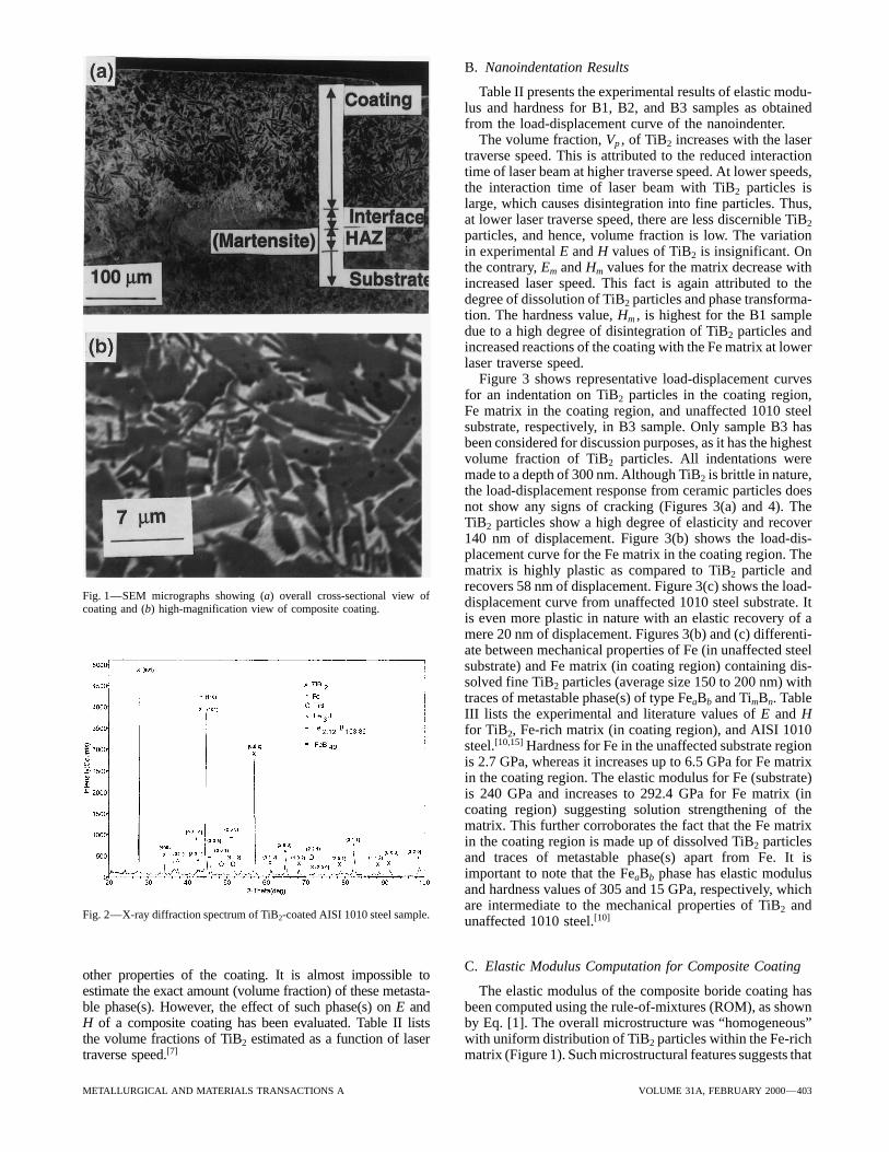
tioned using a slow-speed Buehler Isomet diamond saw. These drites and ultrafine dissolved boride particles.[7] Figure 2 is anX-ray diffraction spectrum of the TiB2-coated steel surface.samples were further mechanically ground to approximately
300-mm thickness. A 2-mm-square section of this sample was TiB2 is the major phase present in the coating. Additionally,a few small peaks of metastable phase(s) of type FeaBb andmounted on an epoxy stub and was further ground and polished
to approximately 150-mm thickness using a Buehler Isomet TimBn are also observed. Such metastable phase formation isattributed to high energy input combined with high coolingMinimet Polisher. All of these steps were conducted to assure
removal of the entire substrate material (AISI 1010 steel) such rate by self-quenching provided by laser processing.[8,14] Lasersurface engineering is a nonequilibrium synthesis that involvesthat TEM samples were made only out of the composite
coating, which was 150-mm thick. A Gatan 656 dimple grinder high cooling rates (103 to 108 K/s) producing metastablephase(s) and a wide variety of microstructures with novelwas used for thinning the sample up to 20 mm. The sample
was very fragile at this stage. It was mounted on a carbon properties that cannot be produced by any conventional pro-cessing technique.[14] Though such metastable phase(s) mayring for support and then final polishing was done by ion
milling for 6 hours at a setting of 6.5 kV on a twin gun Gatan be present in traces, they can possibly affect mechanical and
402—VOLUME 31A, FEBRUARY 2000 METALLURGICAL AND MATERIALS TRANSACTIONS A
B. Nanoindentation Results
Table II presents the experimental results of elastic modu-lus and hardness for B1, B2, and B3 samples as obtainedfrom the load-displacement curve of the nanoindenter.
The volume fraction, Vp , of TiB2 increases with the lasertraverse speed. This is attributed to the reduced interactiontime of laser beam at higher traverse speed. At lower speeds,the interaction time of laser beam with TiB2 particles islarge, which causes disintegration into fine particles. Thus,at lower laser traverse speed, there are less discernible TiB2
particles, and hence, volume fraction is low. The variationin experimental E and H values of TiB2 is insignificant. Onthe contrary, Em and Hm values for the matrix decrease withincreased laser speed. This fact is again attributed to thedegree of dissolution of TiB2 particles and phase transforma-tion. The hardness value, Hm , is highest for the B1 sampledue to a high degree of disintegration of TiB2 particles andincreased reactions of the coating with the Fe matrix at lowerlaser traverse speed.
Figure 3 shows representative load-displacement curvesfor an indentation on TiB2 particles in the coating region,Fe matrix in the coating region, and unaffected 1010 steelsubstrate, respectively, in B3 sample. Only sample B3 hasbeen considered for discussion purposes, as it has the highestvolume fraction of TiB2 particles. All indentations weremade to a depth of 300 nm. Although TiB2 is brittle in nature,the load-displacement response from ceramic particles doesnot show any signs of cracking (Figures 3(a) and 4). TheTiB2 particles show a high degree of elasticity and recover140 nm of displacement. Figure 3(b) shows the load-dis-placement curve for the Fe matrix in the coating region. Thematrix is highly plastic as compared to TiB2 particle andrecovers 58 nm of displacement. Figure 3(c) shows the load-
Fig. 1—SEM micrographs showing (a) overall cross-sectional view of displacement curve from unaffected 1010 steel substrate. Itcoating and (b) high-magnification view of composite coating.is even more plastic in nature with an elastic recovery of amere 20 nm of displacement. Figures 3(b) and (c) differenti-ate between mechanical properties of Fe (in unaffected steelsubstrate) and Fe matrix (in coating region) containing dis-solved fine TiB2 particles (average size 150 to 200 nm) withtraces of metastable phase(s) of type FeaBb and TimBn. TableIII lists the experimental and literature values of E and Hfor TiB2, Fe-rich matrix (in coating region), and AISI 1010steel.[10,15] Hardness for Fe in the unaffected substrate regionis 2.7 GPa, whereas it increases up to 6.5 GPa for Fe matrixin the coating region. The elastic modulus for Fe (substrate)is 240 GPa and increases to 292.4 GPa for Fe matrix (incoating region) suggesting solution strengthening of thematrix. This further corroborates the fact that the Fe matrixin the coating region is made up of dissolved TiB2 particlesand traces of metastable phase(s) apart from Fe. It isimportant to note that the FeaBb phase has elastic modulusand hardness values of 305 and 15 GPa, respectively, whichare intermediate to the mechanical properties of TiB2 and
Fig. 2—X-ray diffraction spectrum of TiB2-coated AISI 1010 steel sample. unaffected 1010 steel.[10]
C. Elastic Modulus Computation for Composite Coatingother properties of the coating. It is almost impossible toestimate the exact amount (volume fraction) of these metasta- The elastic modulus of the composite boride coating has
been computed using the rule-of-mixtures (ROM), as shownble phase(s). However, the effect of such phase(s) on E andH of a composite coating has been evaluated. Table II lists by Eq. [1]. The overall microstructure was “homogeneous”
with uniform distribution of TiB2 particles within the Fe-richthe volume fractions of TiB2 estimated as a function of lasertraverse speed.[7] matrix (Figure 1). Such microstructural features suggests that
METALLURGICAL AND MATERIALS TRANSACTIONS A VOLUME 31A, FEBRUARY 2000—403
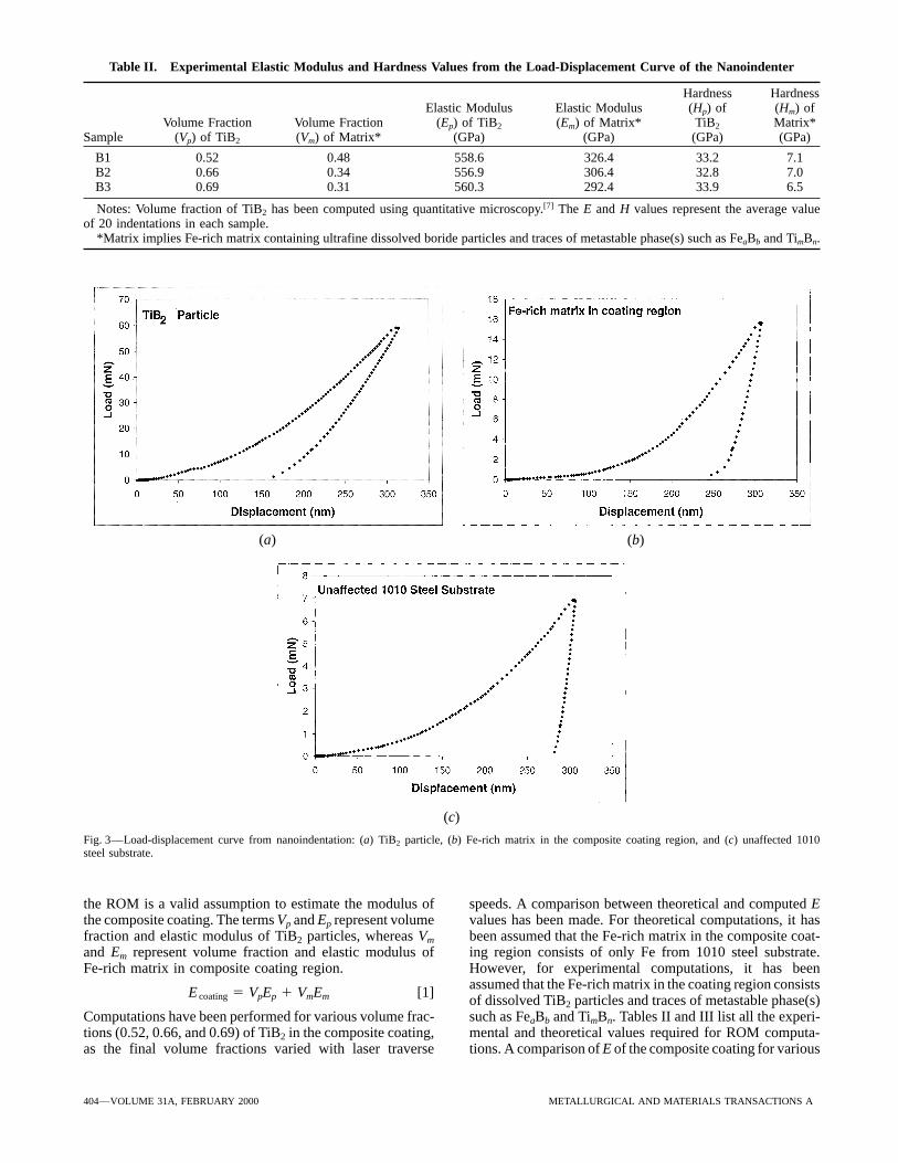
Table II. Experimental Elastic Modulus and Hardness Values from the Load-Displacement Curve of the Nanoindenter
Hardness HardnessElastic Modulus Elastic Modulus (Hp) of (Hm) of
Volume Fraction Volume Fraction (Ep) of TiB2 (Em) of Matrix* TiB2 Matrix*Sample (Vp) of TiB2 (Vm) of Matrix* (GPa) (GPa) (GPa) (GPa)
B1 0.52 0.48 558.6 326.4 33.2 7.1B2 0.66 0.34 556.9 306.4 32.8 7.0B3 0.69 0.31 560.3 292.4 33.9 6.5
Notes: Volume fraction of TiB2 has been computed using quantitative microscopy.[7] The E and H values represent the average valueof 20 indentations in each sample.
*Matrix implies Fe-rich matrix containing ultrafine dissolved boride particles and traces of metastable phase(s) such as FeaBb and TimBn.
(a) (b)
(c)
Fig. 3—Load-displacement curve from nanoindentation: (a) TiB2 particle, (b) Fe-rich matrix in the composite coating region, and (c) unaffected 1010steel substrate.
the ROM is a valid assumption to estimate the modulus of speeds. A comparison between theoretical and computed Evalues has been made. For theoretical computations, it hasthe composite coating. The terms Vp and Ep represent volume
fraction and elastic modulus of TiB2 particles, whereas Vm been assumed that the Fe-rich matrix in the composite coat-ing region consists of only Fe from 1010 steel substrate.and Em represent volume fraction and elastic modulus of
Fe-rich matrix in composite coating region. However, for experimental computations, it has beenassumed that the Fe-rich matrix in the coating region consists
E coating 5 VpEp 1 VmEm [1] of dissolved TiB2 particles and traces of metastable phase(s)such as FeaBb and TimBn. Tables II and III list all the experi-Computations have been performed for various volume frac-
tions (0.52, 0.66, and 0.69) of TiB2 in the composite coating, mental and theoretical values required for ROM computa-tions. A comparison of E of the composite coating for variousas the final volume fractions varied with laser traverse
404—VOLUME 31A, FEBRUARY 2000 METALLURGICAL AND MATERIALS TRANSACTIONS A
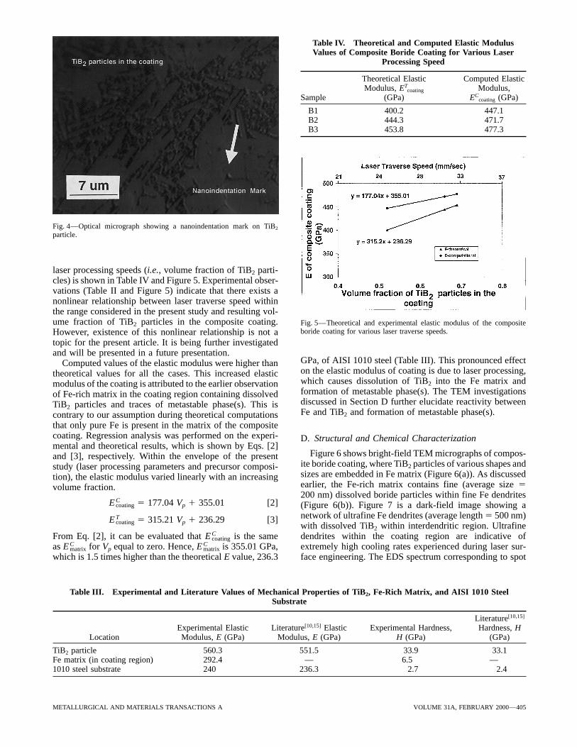
Table IV. Theoretical and Computed Elastic ModulusValues of Composite Boride Coating for Various Laser
Processing Speed
Theoretical Elastic Computed ElasticModulus, ET
coating Modulus,Sample (GPa) EC
coating (GPa)
B1 400.2 447.1B2 444.3 471.7B3 453.8 477.3
Fig. 4—Optical micrograph showing a nanoindentation mark on TiB2
particle.
laser processing speeds (i.e., volume fraction of TiB2 parti-cles) is shown in Table IV and Figure 5. Experimental obser-vations (Table II and Figure 5) indicate that there exists anonlinear relationship between laser traverse speed withinthe range considered in the present study and resulting vol-ume fraction of TiB2 particles in the composite coating. Fig. 5—Theoretical and experimental elastic modulus of the composite
boride coating for various laser traverse speeds.However, existence of this nonlinear relationship is not atopic for the present article. It is being further investigatedand will be presented in a future presentation.
GPa, of AISI 1010 steel (Table III). This pronounced effectComputed values of the elastic modulus were higher thanon the elastic modulus of coating is due to laser processing,theoretical values for all the cases. This increased elasticwhich causes dissolution of TiB2 into the Fe matrix andmodulus of the coating is attributed to the earlier observationformation of metastable phase(s). The TEM investigationsof Fe-rich matrix in the coating region containing dissolveddiscussed in Section D further elucidate reactivity betweenTiB2 particles and traces of metastable phase(s). This isFe and TiB2 and formation of metastable phase(s).contrary to our assumption during theoretical computations
that only pure Fe is present in the matrix of the compositecoating. Regression analysis was performed on the experi- D. Structural and Chemical Characterizationmental and theoretical results, which is shown by Eqs. [2]
Figure 6 shows bright-field TEM micrographs of compos-and [3], respectively. Within the envelope of the presentite boride coating, where TiB2 particles of various shapes andstudy (laser processing parameters and precursor composi-sizes are embedded in Fe matrix (Figure 6(a)). As discussedtion), the elastic modulus varied linearly with an increasingearlier, the Fe-rich matrix contains fine (average size 5volume fraction.200 nm) dissolved boride particles within fine Fe dendrites
E Ccoating 5 177.04 Vp 1 355.01 [2] (Figure 6(b)). Figure 7 is a dark-field image showing a
network of ultrafine Fe dendrites (average length 5 500 nm)E Tcoating 5 315.21 Vp 1 236.29 [3]
with dissolved TiB2 within interdendritic region. Ultrafinedendrites within the coating region are indicative ofFrom Eq. [2], it can be evaluated that E C
coating is the sameas E C
matrix for Vp equal to zero. Hence, E Cmatrix is 355.01 GPa, extremely high cooling rates experienced during laser sur-
face engineering. The EDS spectrum corresponding to spotwhich is 1.5 times higher than the theoretical E value, 236.3
Table III. Experimental and Literature Values of Mechanical Properties of TiB2, Fe-Rich Matrix, and AISI 1010 SteelSubstrate
Literature[10,15]
Experimental Elastic Literature[10,15] Elastic Experimental Hardness, Hardness, HLocation Modulus, E (GPa) Modulus, E (GPa) H (GPa) (GPa)
TiB2 particle 560.3 551.5 33.9 33.1Fe matrix (in coating region) 292.4 — 6.5 —1010 steel substrate 240 236.3 2.7 2.4
METALLURGICAL AND MATERIALS TRANSACTIONS A VOLUME 31A, FEBRUARY 2000—405
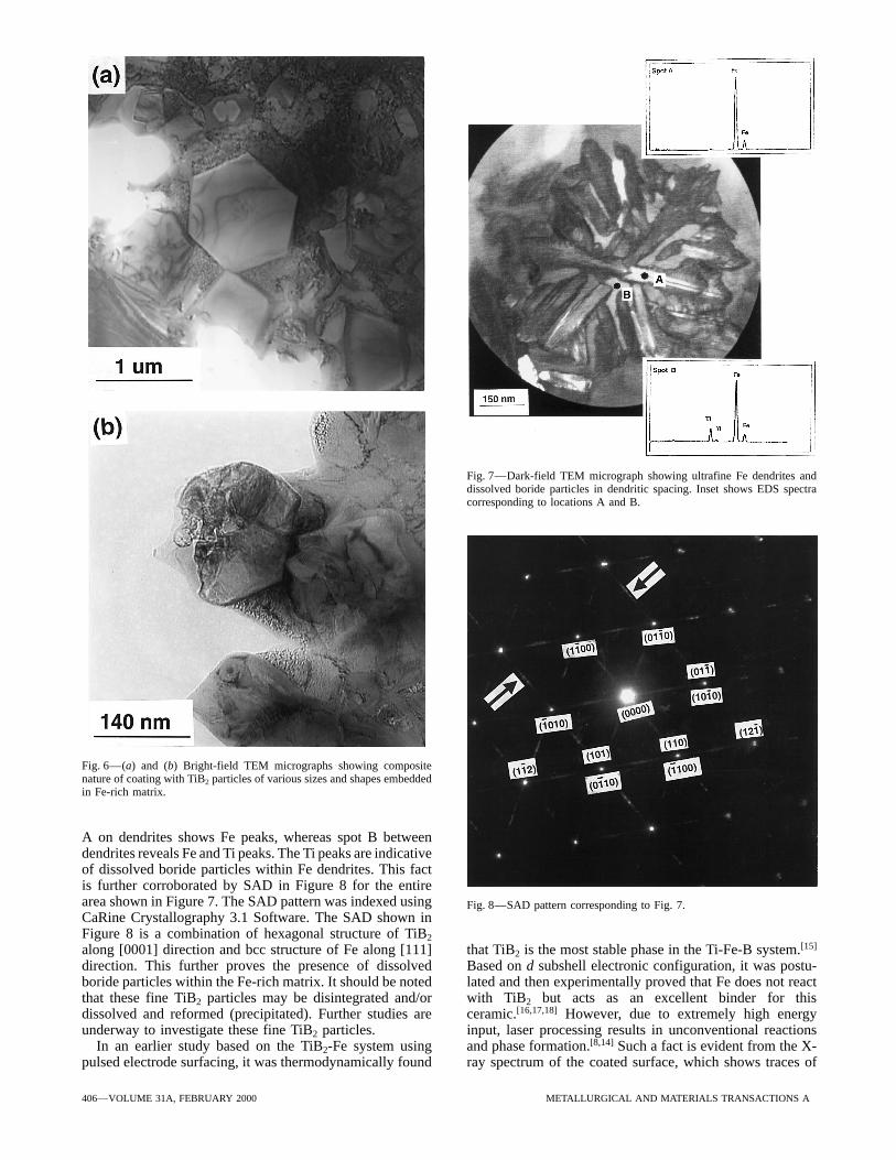
Fig. 7—Dark-field TEM micrograph showing ultrafine Fe dendrites anddissolved boride particles in dendritic spacing. Inset shows EDS spectracorresponding to locations A and B.
Fig. 6—(a) and (b) Bright-field TEM micrographs showing compositenature of coating with TiB2 particles of various sizes and shapes embeddedin Fe-rich matrix.
A on dendrites shows Fe peaks, whereas spot B betweendendrites reveals Fe and Ti peaks. The Ti peaks are indicativeof dissolved boride particles within Fe dendrites. This factis further corroborated by SAD in Figure 8 for the entirearea shown in Figure 7. The SAD pattern was indexed using Fig. 8—SAD pattern corresponding to Fig. 7.CaRine Crystallography 3.1 Software. The SAD shown inFigure 8 is a combination of hexagonal structure of TiB2
along [0001] direction and bcc structure of Fe along [111] that TiB2 is the most stable phase in the Ti-Fe-B system.[15]
Based on d subshell electronic configuration, it was postu-direction. This further proves the presence of dissolvedboride particles within the Fe-rich matrix. It should be noted lated and then experimentally proved that Fe does not react
with TiB2 but acts as an excellent binder for thisthat these fine TiB2 particles may be disintegrated and/ordissolved and reformed (precipitated). Further studies are ceramic.[16,17,18] However, due to extremely high energy
input, laser processing results in unconventional reactionsunderway to investigate these fine TiB2 particles.In an earlier study based on the TiB2-Fe system using and phase formation.[8,14] Such a fact is evident from the X-
ray spectrum of the coated surface, which shows traces ofpulsed electrode surfacing, it was thermodynamically found
406—VOLUME 31A, FEBRUARY 2000 METALLURGICAL AND MATERIALS TRANSACTIONS A
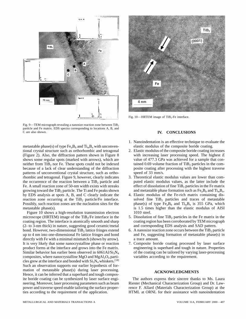
Fig. 10—HRTEM image of TiB2-Fe interface.
Fig. 9—TEM micrograph revealing a nanosize reaction zone between TiB2
particle and Fe matrix. EDS spectra corresponding to locations A, B, andC are also shown. IV. CONCLUSIONS
1. Nanoindentation is an effective technique to evaluate theelastic modulus of the composite boride coating.metastable phase(s) of type FeaBb and TimBn with unconven-
2. Elastic modulus of the composite boride coating increasestional crystal structure such as orthorhombic and tetragonalwith increasing laser processing speed. The highest E(Figure 2). Also, the diffraction pattern shown in Figure 8value of 477.3 GPa was achieved for a sample that con-shows some regular spots (marked with arrows), which aretained 0.69 volume fraction of TiB2 particles in the com-neither from TiB2 nor Fe. These spots could not be indexedposite coating after processing with the highest traversebecause of a lack of clear understanding of the diffractionspeed of 33 mm/s.patterns of unconventional crystal structure, such as ortho-
3. Theoretical elastic modulus values are lower than com-rhombic and tetragonal. Figure 9, however, clearly indicatesputed elastic modulus values, as the latter include thethe occurrence of the reaction between a TiB2 particle andeffect of dissolution of fine TiB2 particles in the Fe matrixFe. A small reaction zone of 50-nm width exists with streaksand metastable phase formation such as FeaBb and TimBn.growing toward the TiB2 particle. The Ti and Fe peaks shown
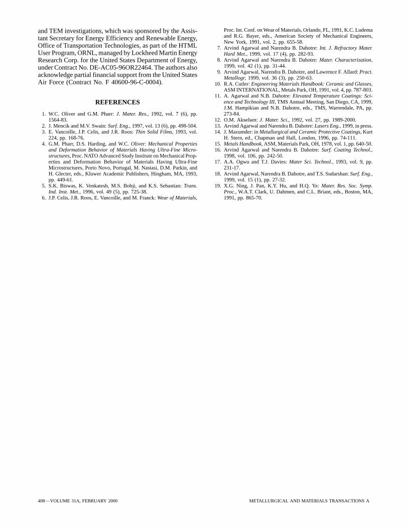
4. Elastic modulus of the Fe-rich matrix containing dis-by EDS analysis at spots A, B, and C clearly indicate thesolved fine TiB2 particles and traces of metastablereaction zone occurring at the TiB2 particle/Fe interface.phase(s) of type FeaBb and TimBn is 355 GPa, whichPossibly, such reaction zones are the nucleation sites for theis 1.5 times higher than the elastic modulus of AISImetastable phase(s).1010 steel.Figure 10 shows a high-resolution transmission electron
5. Dissolution of fine TiB2 particles in the Fe matrix in themicroscope (HRTEM) image of the TiB2/Fe interface in thecoating region has been corroborated by TEM micrographcoating region. The interface is atomically smooth and sharpand corresponding EDS analysis and SAD pattern.(2- to 3-nm thick) in nature, suggesting good ceramic/metal
6. A nanosize reaction zone occurs between the TiB2 particlebond. However, two-dimensional TiB2 lattice fringes extendand Fe, suggesting formation of metastable phase(s) inup to 4 nm into one-dimensional Fe lattice fringes and bonda trace amount.directly with Fe with a minimal mismatch (shown by arrow).
7. Composite boride coating processed by laser surfaceIt is very likely that some nanocrystalline phase or reactionengineering is superhard and tough in nature. Propertiesproduct forms at the interface and grows into the Fe matrix.of the coating can be tailored by varying laser-processingSimilar behavior has earlier been observed in 6061Al/Si3N4
variables according to the requirement.composites, where nanocrystalline MgO and MgAl2O4 parti-cles grew at the interface and bonded with Si3N4 whiskers.[18]
Such an observation supports our earlier hypothesis of for-mation of metastable phase(s) during laser processing. ACKNOWLEDGMENTSHence, it can be inferred that a superhard and tough compos-ite boride coating can be synthesized by laser surface engi- The authors express their sincere thanks to Ms. Laura
Riester (Mechanical Characterization Group) and Dr. Law-neering. Moreover, laser processing parameters such as beampower and traverse speed enable tailoring the surface proper- rence F. Allard (Materials Characterization Group) at the
HTML at ORNL for their assistance with nanoindentationties according to the requirement of the application.
METALLURGICAL AND MATERIALS TRANSACTIONS A VOLUME 31A, FEBRUARY 2000—407
Proc. Int. Conf. on Wear of Materials, Orlando, FL, 1991, K.C. Ludemaand TEM investigations, which was sponsored by the Assis-and R.G. Bayer, eds., American Society of Mechanical Engineers,tant Secretary for Energy Efficiency and Renewable Energy,New York, 1991, vol. 2, pp. 655-58.
Office of Transportation Technologies, as part of the HTML 7. Arvind Agarwal and Narendra B. Dahotre: Int. J. Refractory Mater.User Program, ORNL, managed by Lockheed Martin Energy Hard Met., 1999, vol. 17 (4), pp. 282-93.
8. Arvind Agarwal and Narendra B. Dahotre: Mater. Characterization,Research Corp. for the United States Department of Energy,1999, vol. 42 (1), pp. 31-44.under Contract No. DE-AC05-96OR22464. The authors also
9. Arvind Agarwal, Narendra B. Dahotre, and Lawrence F. Allard: Pract.acknowledge partial financial support from the United States Metallogr, 1999, vol. 36 (3), pp. 250-63.Air Force (Contract No. F 40600-96-C-0004). 10. R.A. Cutler: Engineering Materials Handbook: Ceramic and Glasses,
ASM INTERNATIONAL, Metals Park, OH, 1991, vol. 4, pp. 787-803.11. A. Agarwal and N.B. Dahotre: Elevated Temperature Coatings: Sci-
ence and Technology III, TMS Annual Meeting, San Diego, CA, 1999,REFERENCESJ.M. Hampikian and N.B. Dahotre, eds., TMS, Warrendale, PA, pp.273-84.1. W.C. Oliver and G.M. Pharr: J. Mater. Res., 1992, vol. 7 (6), pp.
1564-83. 12. O.M. Akselsen: J. Mater. Sci., 1992, vol. 27, pp. 1989-2000.13. Arvind Agarwal and Narendra B. Dahotre: Lasers Eng., 1999, in press.2. J. Mencik and M.V. Swain: Surf. Eng., 1997, vol. 13 (6), pp. 498-504.
3. E. Vancoille, J.P. Celis, and J.R. Roos: Thin Solid Films, 1993, vol. 14. J. Mazumder: in Metallurgical and Ceramic Protective Coatings, KurtH. Stern, ed., Chapman and Hall, London, 1996, pp. 74-111.224, pp. 168-76.
4. G.M. Pharr, D.S. Harding, and W.C. Oliver: Mechanical Properties 15. Metals Handbook, ASM, Materials Park, OH, 1978, vol. 1, pp. 640-50.16. Arvind Agarwal and Narendra B. Dahotre: Surf. Coating Technol.,and Deformation Behavior of Materials Having Ultra-Fine Micro-
structures, Proc. NATO Advanced Study Institute on Mechanical Prop- 1998, vol. 106, pp. 242-50.17. A.A. Ogwu and T.J. Davies: Mater Sci. Technol., 1993, vol. 9, pp.erties and Deformation Behavior of Materials Having Ultra-Fine
Microstructures, Porto Novo, Portugal, M. Nastasi, D.M. Parkin, and 231-17.18. Arvind Agarwal, Narendra B. Dahotre, and T.S. Sudarshan: Surf. Eng.,H. Glecter, eds., Kluwer Academic Publishers, Hingham, MA, 1993,
pp. 449-61. 1999, vol. 15 (1), pp. 27-32.19. X.G. Ning, J. Pan, K.Y. Hu, and H.Q. Ye: Mater. Res. Soc. Symp.5. S.K. Biswas, K. Venkatesh, M.S. Bobji, and K.S. Sebastian: Trans.
Ind. Inst. Met., 1996, vol. 49 (5), pp. 725-38. Proc., W.A.T. Clark, U. Dahmen, and C.L. Briant, eds., Boston, MA,1991, pp. 865-70.6. J.P. Celis, J.R. Roos, E. Vancoille, and M. Franck: Wear of Materials,
408—VOLUME 31A, FEBRUARY 2000 METALLURGICAL AND MATERIALS TRANSACTIONS A