Embed Size (px)
Citation preview

Mechanical Properties and Microstructure of AI-Li-Cu-Mg-Zr Die Forgings
DONALD WEBSTER and RICHARD KIRKBRIDE
Four forgings of A1 8090 alloy were evaluated for strength, toughness, and stress corrosion resistance. A microstructural evaluation was also conducted. The forgings easily met the strength requirements for A1 7075-T73 but only just met the 7 pct minimum elongation requirement. The stress corrosion threshold was less than 35 MPa in the short transverse orientation, a value that is far below the 310 MPa minimum often required for A1 7075-T73. Fracture in areas which received low forging reductions was intergranular, while fracture in more heavily forged areas was also along subgrain boundaries. Possible mechanisms for the low toughness and stress corrosion resistance of A1-Li alloys are discussed.
I. INTRODUCTION
THE aerospace industry is presently in the initial stages of replacing existing high strength and high toughness alumi- num alloys, such as A1 7075 and A1 2024, by low density A1-Li alloys. This will result in an 8 to 12 pct reduction in weight, 1 providing the A1-Li alloys can be produced with certain minimum mechanical properties. The properties that are used in aircraft design, e.g., strength, toughness, stress corrosion resistance, and fatigue crack growth, should be equivalent to those of existing alloys to avoid the need for structural redesign. At the present time, there are concerns regarding the short transverse toughness and stress corro- sion resistance of A1-Li alloys, 2,3 particularly when proper- ties equivalent to A1 7075-T73 are required. The present program was designed to determine whether A1 8090 forg- ings could be substituted for parts which presently use A1 7075-T73.
II. MATERIAL
The composition of the AI 8090 used in this work is shown in Table I. The bulk hydrogen content was deter- mined by Leco Corporation using a technique which melts the alloy under a stream of nitrogen gas and determines the hydrogen content from the change in thermal conductivity. Bulk hydrogen and surface hydrogen contents were deter- mined, but only the bulk hydrogen is reported here.
The bulk hydrogen content of 0.3 ppm is considerably higher than the values obtained on conventional aerospace quality aluminum alloys by the same technique (0.03 to 0.08 ppm), but is amongst the lowest values obtained for A1-Li alloys such as A1 8090 and A1 2090 which have been found to be in the range 0.3 to 0.8 ppm. 4 The sodium and po- tassium contents were determined by flame atomic emission.
DONALD WEBSTER, formerly Senior Staff Research Engineer, Kaiser Aluminum & Chemical Corporation, Pleasanton, CA 94566, is a Metal- lurgical Consultant, 20565 Verde Vista Lane, Saratoga, CA 95070. RICHARD KIRKBRIDE is Quality Control Representative, Boeing Com- pany, Glendale, CA 91203.
Manuscript submitted November 5, 1985.
III. EXPERIMENTAL PROCEDURE
Four small die forgings were made at Kaiser Aluminum & Chemical Corporation's Oxnard Forging plant. The forg- ings were made from sections of a 6.4 cm-diameter ex- trusion, machined from a 14.6 cm-thick rolling block of A1-Li-Cu-Mg-Zr.
The rolling block was turned to 12.7 cm diameter, ho- mogenized for 4 hours at 790 K, air cooled, reheated to 744 K, and extruded to 6.4 cm diameter. Pieces of this extrusion, 10.2 cm long, were used for each forging. The forging conditions are given in Table II.
The forgings were solution treated for 1 hour at 790 K, cold water quenched, aged 2 days at room temperature, followed by 48 hours at 444 K. Portions of the original extrusion stock were heat-treated identically so that the lon- gitudinal tensile properties could be measured for com- parison with the forging properties.
Test specimens were cut from the forgings as shown in Figures 1 and 2. The original extrusion direction is shown in Figure 1 and the forging direction is shown in Figure 2. The longitudinal tensile specimens which have their axes parallel to the original extrusion direction and the long trans- verse tensile specimens (perpendicular to both the extrusion and forging directions) were round specimens 6.4 cm long with a gage length of 2.54 cm and a diameter of 0.64 cm. The short transverse tensile specimens, i.e., parallel to the forging direction, had a diameter of 0.32 cm and a gage length of 1.27 cm. The Charpy specimens which were stan- dard 1 cm square with a notch radius of 0.25 mm were tested on a Manlabs 32J impact machine. The fracture toughness was determined from chevron notched short bar specimens 1.27 cm by 1.1 cm by 1.9 cm according to SAE- ARP 1704 recommended practice. Stress corrosion data in the short transverse direction were determined from C-rings with a thickness of 4.6 mm and an outer diameter of 2.4 cm and round tensile specimens with a diameter of 3.2 mm. The C-rings were placed so that their most highly stressed regions were as close as possible to the region of maximum transverse grain flow at the parting plane. The tings were stressed at 34.5 and 69 MPa and alternately immersed in 3.5 pct NaC1 solution for 30 days according to ASTM G44. Intergranular stress corrosion cracking was verified by metallographic examination.
METALLURGICAL TRANSACTIONS A VOLUME 17A, NOVEMBER 1986--2007

Table I. Chemical Composition of A! 8090 Forgings
Composition Weight Percent PPM
Li Cu Mg Zr Fe Si H Na K
2.45 1.18 0.57 0.12 0.10 0.05 0.3 1.6 0.4
Table II. Forging Conditions
Forging Maximum Reheating Forging Number Temperature (K) Temperature (K)
3 720 720 4 720 720 5 720 670 6 720 670
�9 CHAI~,
.5
EXT~US ION DIP, ECTI ON
Fig. 1 --Specimen layout for forgings #3 and #5 showing original extru- sion direction.
FORGING
DIP~ECTION
[ LONGT. TENSILE
s [ LONGT. TENSILE
Fig. 2--Specimen layout for forgings #4 and #6 showing forging direction.
IN RESULTS
A. Microstructure
The forging after solution treatment and aging is shown in Figure 3. Samples for microstructural evaluation were cut out from area A. A macrograph from this area is shown in Figure 4 for forging 4. The top and bottom 0.5 cm of the forging is heavily worked, while the center shows the rela- tively undeformed coarse grain structure of the original extrusion. At higher magnifications, the grain size can be resolved only at the center of the forging (Figure 5) but at still higher magnifications, the subgrain size in the heavily Fig. 3--Forging #3 after heat treatment.
2008--VOLUME 17A, NOVEMBER 1986 METALLURGICAL TRANSACTIONS A

Fig. 4--Macrograph of area A from forging #4 after heat treatment.
worked surface layers can be resolved (Figure 6). The aver- age linear intercept is 6.8/zm in the direction of working and 2.6/zm at right angles to the direction of metal flow.
The grain size in the region midway between the surface and center of the forging shows a mixture of unrecrystallized areas and bands of fine grains and subgrains of a similar size to those observed near the surface.
Electron micrographs of the center (unworked by forging) and surface (heavily worked by forging) in the -T6 condition (aged 48 hours 444 K) are shown in Figure 7. The un- worked center of the forging shows a subgrain structure 2.5 to 15/zm diameter. Inside the subgrains are helical dis-
Fig. 6--Opt ical micrograph of surface grain size of forging #4 after heat treatment.
location loops, not completely resolved because of the high volume fraction of A13Li precipitates 10 to 15 nm diameter in the background. The heavily worked surface regions of the forging show a fine grain (2.5 to 6.5/xm diameter) structure usually described as unrecrystallized. The grain structure in Figure 7 is taken from an area farther from the outer surface of the forging than the optical micrograph shown in Figure 6 and so shows a more equiaxed subgrain
(a) Fig. 5--Micrographs of area A from forging #3 after heat treatment. (a) Surface, (b) center.
(b)
METALLURGICAL TRANSACTIONS A VOLUME 17A, NOVEMBER 1986--2009
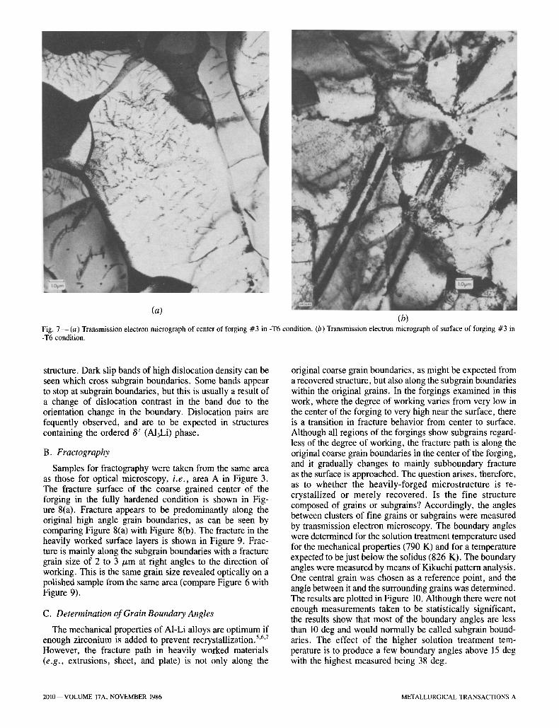
(a) (b) Fig. 7 - (a) Transmission electron micrograph of center of forging #3 in -T6 condition. (b) Transmission electron micrograph of surface of forging #3 in -T6 condition.
structure. Dark slip bands of high dislocation density can be seen which cross subgrain boundaries. Some bands appear to stop at subgrain boundaries, but this is usually a result of a change of dislocation contrast in the band due to the orientation change in the boundary. Dislocation pairs are fequently observed, and are to be expected in structures containing the ordered ~' (A13Li) phase.
B. Fractography
Samples for fractography were taken from the same area as those for optical microscopy, i.e., area A in Figure 3. The fracture surface of the coarse grained center of the forging in the fully hardened condition is shown in Fig- ure 8(a). Fractur~ appears to be predominantly along the original high angle grain boundaries, as can be seen by comparing Figure 8(a) with Figure 8(b). The fracture in the heavily worked surface layers is shown in Figure 9. Frac- ture is mainly along the subgrain boundaries with a fracture grain size of 2 to 3 ~m at right angles to the direction of working. This is the same grain size revealed optically on a polished sample from the same area (compare Figure 6 with Figure 9).
C. Determination of Grain Boundary Angles
The mechanical properties of A1-Li alloys are optimum if enough zirconium is added to prevent recrystallization. 5'6'7 However, the fracture path in heavily worked materials (e.g., extrusions, sheet, and plate) is not only along the
original coarse grain boundaries, as might be expected from a recovered structure, but also along the subgrain boundaries within the original grains. In the forgings examined in this work, where the degree of working varies from very low in the center of the forging to very high near the surface, there is a transition in fracture behavior from center to surface. Although all regions of the forgings show subgrains regard- less of the degree of working, the fracture path is along the original coarse grain boundaries in the center of the forging, and it gradually changes to mainly subboundary fracture as the surface is approached. The question arises, therefore, as to whether the heavily-forged microstructure is re- crystallized or merely recovered. Is the fine structure composed of grains or subgrains? Accordingly, the angles between clusters of fine grains or subgrains were measured by transmission electron microscopy. The boundary angles were determined for the solution treatment temperature used for the mechanical properties (790 K) and for a temperature expected to be just below the solidus (826 K). The boundary angles were measured by means of Kikuchi pattern analysis. One central grain was chosen as a reference point, and the angle between it and the surrounding grains was determined. The results are plotted in Figure 10. Although there were not enough measurements taken to be statistically significant, the results show that most of the boundary angles are less than 10 deg and would normally be called subgrain bound- aries. The effect of the higher solution treatment tem- perature is to produce a few boundary angles above 15 deg with the highest measured being 38 deg.
2010--VOLUME 17A, NOVEMBER 1986 METALLURGICAL TRANSACTIONS A

(a) Fig, 9--Scanning electron micrograph of the fracture surface of forging #5 in the heavily forged surface region.
lO0
Solution Treated 792K, 1 h.
13 grain- boundaries measured
r--If 50
o 0-5
Solution Treated 827K, l h.
19 grain boundaries measured
I I , I I I 6-I0 l l -20 21-40
GRAIN BOU,~DARY ANGLE (DEGREES)
Fig. 10--Measurements of grain boundary angles by TEM in the surface regions of forging #3, solution treated at 792 K 1 h and 827 K 1 h.
(b) Fig. 8 - - ( a ) Scanning electron micrograph of fracture surface of forging #5 in the -T6 condition showing fracture along coarse grain boundaries. (b) Optical micrograph of center region of forging #5 showing a coarse grain structure which fractures along grain boundaries as shown in (a).
D. Mechanical Properties
The tensile properties in the longitudinal, long transverse, and short transverse directions are listed in Table III. The longitudinal tensile properties of the identically heat-treated (aged 48 hours 444 K) original extrusion stock were UTS 500 MPa, 0.2 pct yield strength, 454 MPa, and elongation
METALLURGICAL TRANSACTIONS A VOLUME I7A, NOVEMBER 1986--2011

Table HI. Tensile Properties
Forging Number Test Direction UTS, MPa 0.2 Pct Y.S., MPa E1 Pct
4 (720 K) long transverse 458 395 4 4 (720 K) longitudinal 497 451 8 4 (720 K) longitudinal 500 457 7 4 (720 K) longitudinal 484 422 8 4 (720 K) longitudinal 499 453 8 3 (720 K) short transverse 391 322 3.2 6 (670 K) long transverse 458 412 3 6 (670 K) longitudinal 510 470 7 6 (670 K) longitudinal 510 471 6 6 (670 K) longitudinal 546 453 10 6 (670 K) longitudinal 528 503 8 5 (670 K) short transverse 387 332 2.4
5 pct. The short bar fracture toughness values and the Charpy impact values are listed in Table IV.
E. Stress Corrosion Properties
C-rings taken adjacent to the parting line and tested at 69 MPa had visible cracks after 10 days exposure. Cracking was intergranular. Tensile specimens in the short trans- verse direction tested at 34 MPa and 69 MPa showed stress corrosion crack growth and intergranular attack along sub- grain boundaries (Figure 11). The full results are given in Table V.
E Surface Slip Studies
Slip lines formed on polished and lightly etched surfaces of the forging after deformation at room temperature were examined in both the -T4 and -T6 conditions. The slip distribution was similar in both cases. At low levels of cold deformation, parallel bands of slip lines could be seen across the coarse original grains in the center of the forging. In the heavily forged surface layers where well-defined subgrains
Table IV. Short Bar Fracture Toughness Values and Charpy Impact Values
Forging Notch KSB Charpy Value Number Orientation MPa~/--mm J
3 (720 K) ST 24.2 - - 3 (720 K) ST 24.5 - - 3 (720 K) LT - - 7.2 3 (720 K) LT - - 6.7 5 (670 K) ST 21.6 - - 5 (670 K) ST 20.6 - - 5 (670 K) LT - - 6.9 5 (670 K) LT - - 6.4
Fig. 11--Stress corrosion cracking on short transverse tensile specimens taken from the body of forging #5.
exist, the slip lines are more irregular and are interrupted by surface steps 2.5 to 10/xm apart. The slip lines on the surface of a heavily forged area in the -T6 condition with well-defined subgrains are shown in Figure 12. The grain boundaries are heavily pitted by etching in this heat-treated condition. Subgrain boundaries can be seen within the elon- gated original grain boundaries. Slip lines can be seen to be deviated 5 to 10 deg when crossing the subgrain boundaries as would be expected from the measurements in Figure 10. Fracture has occurred at some subgrain boundaries. Heavier cold deformation in a similar microstructure (Figure 13) results in fracture at most subgrain boundaries leading to the type of fracture surfaces shown in Figure 9.
Table V. Stress Corrosion Test Results for A! 8090 Die Forging
Forging Specimen Specimen Location Stress, MPa NF/NT--Failure Time*
3 tensile body 69 1 /2 - - 30 days tensile body 34.5 1 / 1 - - 32 days C-ring parting line 69 1/1 - - 10 days
5 tensile body 69 1 /2 - - 30 days tensile body 34.5 1 / 1 - - 32 days C-ring parting line 69 1/1 - - 10 days
*NF/NT--Number Failed/Number Tested
2012--VOLUME 17A, NOVEMBER 1986 METALLURGICAL TRANSACTIONS A

Fig. 12 - -SEM of surface slip lines in a heavily forged area of forging #5 (827 K-T6).
In view of the possibility of A1-Li alloys being embrittled by impurities which form grain boundary phases which are liquid at room temperature, such as sodium and potas- sium, 8'9 experiments were conducted to look for grain boundary sliding which would be a likely consequence of this. Lines were produced on a polished and etched surface which was then deformed locally with a pointed chisel. A range of deformation from extremely heavy to zero could be obtained in any microstructural region. Substantial grain boundary and subgrain boundary sliding was observed by this technique (Figure 14). The grain boundary displacement ap- pears to be a linear function of the distance from the point of cold work (Figure 15). Samples deformed at 383 K also showed grain boundary sliding, while material deformed at 77 K where liquid phases rich in Na and K would have solidified s show no grain boundary sliding.
V. DISCUSSION
As mentioned in the Introduction, the forgings examined in this report are possible replacements for A1 7075-T73 forgings. The average tensile elongations of the forgings just meet the minimum requirements (7 pet longitudinal, 3 pct transverse) for AI 7075-T73, although strength require- ments are easily met in both longitudinal and transverse directions. The forging process has improved both the longi- tudinal tensile elongation and the tensile strength of the extrusion stock. The fracture toughness values of the mate- rial forged at 720 K are comparable Lo the average typical values for AI 7075-T73 of 23 MPaVm when stressed in the short transverse direction.
Fig. 13 - -SEM of surface slip lines in a heavily forged area of forging #5 (827 K -T6 condition).
Fig. 14--Grain boundary sliding on the surface of forging #5 (827 K -T6) revealed by surface lines on a polished and etched surface.
METALLURGICAL TRANSACTIONS A VOLUME 17A, NOVEMBER 1986--2013

Distance alon E grain bo~/ary
0 0 [] r ~ grahn
- ! c 6
~ 4
~ 2 .5
C.~ I i-I I11 0
0 100 200 300 400 500 600 700
Distance Along Grain Boundary from Point of Impact (~m)
Fig. 15- -Gra in boundary sliding distance as a function of distance from point of deformation in forging #5 (827 K -T6).
However, the stress corrosion threshold of the A1 8090 alloy is less than 35 MPa in the short transverse direction, well below the usual 310 MPa minimum requirement for AI 7075-T73. Stress corrosion tests on plate and extrusions of similar composition have shown low stress corrosion properties (K~scc < 11 MPaMmm for precracked specimens and failure of C-rings at a tensile stress of 69 MPa). 10 Other workers have reported low stress corrosion resistance for A1-Li-Cu-Mg alloys; e .g . , Holroyd, et al. n reported that SSC failures in A1 8090 T651 had been observed in 2.5 days at 240 MPa and 100 days at 100 MPa.
The low ductility and stress corrosion resistance of A1-Li alloys compared to conventional aluminum alloys may be related to their different fracture characteristics. A1-Li alloys aged to high strength conditions fracture along grain bound- aries or subgrain boundaries when tested in air or 3.5 pct NaC1 solution. Alloys such as A1 7050, which contain zir- conium and, like A1-Li alloys, produce unrecrystallized mi- crostructures, fracture in a ductile transgranular manner in air in all tempers. 12 Commercial A1 7075 plate with disc- shaped "pancake" grains 13 and high purity AI 7075 (without chromium) with coarse equiaxed grains 14 also fracture in a ductile, mainly transgranular manner in air.
A universal characteristic of AI-Li alloys produced by present melting and casting techniques is that they contain about 10 times as much hydrogen as other high strength aerospace aluminum alloys. It may be significant, therefore, that the fracture characteristics and low ductility of A1-Li alloys can be duplicated by increasing the hydrogen content of conventional aluminum alloys. This can be done most conveniently by cathodically charging test specimens before or during tensile testing. Higashi et al. found that the hy- drogen content of an A1-8Mg alloy could be increased from 1.2 to 2 cc/100 g by cathodically charging for 10 min- utes at 1 ma/cm 2.15 The charging increased the amount of intergranular fracture and lowered the tensile elongation. Hardwick et al. 12 found that this reduced the tensile ductility of A1 7050 in the underaged and peak-aged conditions by 50 pct. This would make it comparable with the best
A1-Li alloys at the same strength level. The overaged condi- tion of A1 7050 was not affected by charging. The A1 7050 composition without copper was found to be even more drastically affected by charging. In this case, the tensile ductility was found to be reduced 70 pct in the underaged condition and 55 pct in the overaged condition. The effect of hydrogen was to change the ductile transgranular fracture to a mixture of brittle transgranular and intergranular frac- tures. Similar embrittlement by hydrogen was found by Albrecht et al. '3 for A1 7075 who found its effect was temperature dependent and negligible at the temperature of liquid nitrogen (77 K). This indicated that diffusion of hydrogen to fracture sites and a critical local level of hydro- gen were required. Further evidence for the embrittlement being due to hydrogen was the observation that the em- brittlement could be substantially reduced by vacuum de- gassing for 14 days at room temperature.
Even more direct evidence for the role of hydrogen in the fracture of aluminum alloys is available from the work of Ciaraldi et al. ,16 Montgrain and Swann, 17 and Tuck. 18 Ciaraldi found that specimens of an A1-Zn-Mg alloy aged at room temperature in moist air suffered a loss of tensile elongation of up to 60 pct and showed 30 pct intergranular fracture. The grain boundary surfaces showed a brittle layer about 1 /~m thick which was unstable in laboratory air and decomposed to aluminum. Examination of specimens aged in moist air at 343 K and fractured in dry argon indicated the grain boundary layer was A1H3. An important feature of Ciaraldi's work was the demonstration that an exposure to moist air at 343 K of over four days resulted in a type of hydrogen embrittlement that was not strain rate depen- dent; i .e . , there was sufficient hydrogen at the grain bound- aries as A1H3 or in other forms to cause fracture without further diffusion during straining. Tuck observed hydrogen bubbles at grain boundaries of A1-Zn-Mg alloys in thin foils heated by the electron beam, and showed that the evolu- tion of hydrogen from A1-Zn-Mg alloys on heating occurred in the range 670 to 770 K, which was the same range in which pure MgH2 broke down when heated under the same condition.
In A1-Li alloys, a reversible type of embrittlement has been observed by Holroyd et a l . 11 in A1 8090-T651. Sam- ples that were stressed at 240 MPa in 3.5 pct NaC1 failed during subsequent exposure to laboratory air. The time to failure in laboratory air decreased with increasing pre- exposure to 3.5 pct NaC1 solution. Specimens not exposed to the salt solution did not fail in laboratory air. The em- brittlement caused by pre-exposure could be eliminated by a 28-day vacuum treatment, indicating that the em- brittlement was reversible and suggesting that hydrogen em- brittlement may be a factor in the stress corrosion cracking of A1-Li alloys. Christodoulou et al.19 observed a banded structure on the fracture surface of an A1 2.8 Li alloy after a stress corrosion failure. The bands consisted of heavily corroded regions about 50/zm wide followed by minimally corroded regions about 10/xm wide. These were attributed to a discontinuous crack movement where corrosion oc- curred until sufficient hydrogen had built up ahead of the crack tip to cause embrittlement and subsequent failure at the applied stress concentration.
In aluminum alloys not exposed to moisture during ser- vice or testing, the hydrogen they possess is absorbed during melting and casting. Aluminum dissolves about 0.8 ppm of
2014--VOLUME 17A, NOVEMBER 1986 METALLURGICAL TRANSACTIONS A

hydrogen at 973 K, 2~ and the solubility increases rapidly with temperature to approximately 2.5 ppm at 1173 K. Hy- drogen solubility is increased by magnesium, but decreased by copper. Five percent Mg increases the solubility from approximately 0.9 to 1.2 ppm at 973 K. 2j The high hydro- gen contents of A1-Li alloys suggest that lithium increases hydrogen solubility more effectively than the same weight of magnesium. As mentioned above, A1-Li alloys degassed on a commercial scale by various suppliers contain about 10 times the normal level of hydrogen. They could, therefore, be considered equivalent to cathodically charged con- ventional alloys. Lower tensile elongations would therefore be expected; however, more significantly the stress corro- sion properties would be expected to be dramatically re- duced if alkali metal hydrides are produced, since these decompose rapidly on contact with water. Alkali metals, par- ticularly sodium and potassium, are introduced into A1-Li alloys as impurities in the lithium which typically contains about 100 ppm Na and 50 ppm K. As mentioned above, AIH3 and MgH2 have been reported in aluminum alloys where hydrogen levels were artificially increased in the solid state. Alkali metal hydrides (LiH, Nail, KH) are more sta- ble than A1H3 and MgH2 and would be expected to replace them at the grain boundaries of A1-Li alloys. Auger analysis of the fracture surfaces of recrystallized A1-Li alloys has revealed high concentrations of potassium 8'22 and sodium, z3 SIMS analyses of the fracture surfaces of A1-Li-Zr alloys broken under a high vacuum have shown high grain bound- ary concentrations of Na, K, and hydrogen. 9 The grain boundary concentration of these elements was found to in- crease as the lithium content increased.
Vasudrvan 23 has shown that high levels of sodium em- brittle A1-Li alloys, and Webster 9 found that this em- brittlement is enhanced by combinations of sodium and potassium. Webster's results suggest that there are two com- peting embrittlement mechanisms, with the predominant one depending on the aging temperature. In the underaged conditions, the alloys become tougher and more ductile below room temperature, indicating liquid phase em- brittlement by sodium and potassium. In the overaged con- dition, the alloys behave conventionally and become more brittle below room temperature, suggesting the conversion of sodium and potassium to their hydrides, thereby elimi- nating the liquid phases. The sodium and potassium have been observed by TEM to occur on the grain boundaries of AI-Li alloys as discrete lenticular particles. 4 These particles increase in size and number with the Na and K content ranging in size from 0.06/xm long at 1 ppm Na to 1.7/zm long at 476 ppm Na, and in situ EDX analysis indicates that the Na to K ratio is such that the particles are liquid at room temperature according to the phase diagram. Apart from reducing toughness by acting as stress concentrations 24 and by reducing the surface energy of a grain boundary crack, 25 and hence the toughness, 26 the grain boundary liquid par- ticles of Na and K can influence stress corrosion cracking by acting as reservoirs for hydrogen. Hubberstey et ai.27 mea- sured the solubility of hydrogen in Li, K, and Na and found that the solubility increased in the order Na, K, and Li. The solubility of hydrogen in a mixture of Na and K (78 pct K) at a peak aging temperature for A1 8090 of 460 K, according to Hubberstey's data would be 0.014 molecular percent. This is about 25,000 times the solubility of hydrogen in high purity aluminum at 460 K calculated from the data of
Ransley and Neufeld. 28 Hydrogen contents above 0.014 mo- lecular percent in the grain boundary liquid phases would be present as Nail and KH which would dissolve if hydro- gen were diffusing out of the liquid toward the crack tip. A reservoir of hydrogen at a constant potential could be maintained at grain boundary sites by this mechanism, thereby reducing the crack propagation resistance. This could contribute to the low K~s~c values of A1-Li alloys, particularly in the peak and overaged conditions where more hydrogen would have been able to diffuse to grain boundary liquid phases during aging.
The following is a summary of the above factors influ- encing toughness and stress corrosion resistance of A1-Li alloys.
In the solution treated and very underaged conditions, the Na, K, and H are in solid solution, strength is low, tough- ness is high, and fracture is mainly transgranular. 23 Stress corrosion tests on precracked specimens show high K~scc values while unnotched stress corrosion specimens show high failure stresses if the copper content is low so that grain boundary attack cannot occur on copper-rich phases. 1~
As the aging temperatures are increased, Na and K diffuse to grain boundaries and form discrete particles which lower toughness by acting as stress concentrations and/or reducing the surface energy of grain boundary cracks. The fracture path becomes increasingly intergranular as the aging tem- perature is increased 23 and the K~sc~ values are further re- duced, z9 Unnotched stress corrosion specimens of copper containing alloys show increased threshold stresses 4 as the surface corrosion becomes more general and less concen- gated in grain boundaries.
In the overaged condition, Na and K liquid phases have been largely converted to solid phases thought to be hy- drides, 9 toughness and K~cc values are still low, 3 while un- notched specimens of copper containing alloys usually show their greatest resistance to stress corrosion. 1~
The forgings in this work are in the peak aged condition so that their toughness will be reduced by grain boundary liquid phases. These phases will also contain significantly greater amounts of hydrogen than the aluminum matrix and this could accelerate crack propagation in 3.5 pct NaCI solution.
VI. CONCLUSIONS
1. Forgings made from an AI-Li-Cu-Mg-Zr alloy A1 8090 have been made which easily meet the strength require- ments but only just meet the minimum tensile elongation requirements for AI 7075-T73.
2. The fracture toughness of the forgings forged at 720 K is similar to that of forgings of A1 7075-T73 tested in the short transverse direction.
3. The short transverse stress corrosion threshold of the forgings was less than 34 MPa, far less than the 310 MPa minimum value often required for A1 7075-T73 forgings.
4. Fracture of the forgings was along grain boundaries in lightly forged areas and predominantly along subgrain boundaries in heavily forged areas.
5. Grain boundary sliding at room temperature and above was observed at both high angle and low angle grain boundaries and may be related to grain boundary segre- gation of low melting point impurities.
METALLURGICAL TRANSACTIONS A VOLUME 17A, NOVEMBER 1986--2015

ACKNOWLEDGMENTS
The author would like to acknowledge the assistance of the following Kaiser Aluminum & Chemical Corp. person- nel: Ralph Dorward, Wayne Helfrich, Ken Hasse, Ron Foreman, Kevin Brown, George Wolfer, Penny Linde, Glen Franti, Pat Peaslee, Lorraine Casey, and Jack Go.
REFERENCES 1. W.E. Quist, G.H. Narayanan, and A.L. Wingert: Proceedings of
Aluminum-Lithium Alloys II, published by AIME, New York, NY, 1984, pp. 313-34.
2. C.J. Peel, B. Evans, and D. McDarmard: Proceedings of the Aluminum-Lithium Alloys Ill, published by the Institute of Metals, London, 1986, pp. 26-36.
3. A.K. Vasud6van, P.R. Ziman, S.C. JMA, and T.H. Sanders, Jr.: Proceedings of the Aluminum-Lithium Alloys 111, published by the Institute of Metals, London, 1986, pp. 303-09.
4. D. Webster: Kaiser Aluminum & Chemical Corporation, Pleasanton, CA, unpublished research, 1985.
5. E.A. Starke, Jr. and F.S. Lin: Metall. Trans. A, 1982, vol. 13A, pp. 2259-69.
6. C.J. Peel, B. Evans, C. A. Baker, D. A. Bennett, P. J. Gregson, and H.M. Flower: Proceedings of the Second International Aluminum- Lithium Conference at Monterey, April 12-14, 1983, Sanders and Starke, eds., published by AIME.
7. K. Dinsdale, S. J. Harris, and B. Noble: Aluminum-Lithium Alloys, Proceedings of the First International Aluminum-Lithium Conference held at Stone Mountain, GA, May 19-21, 1980, Sanders and Starke, eds., published by AIME.
8. D. Webster: Metal Progress, 1984, vol. 125, No. 5, pp. 33-36. 9. D. Webster: Proceedings of the 3rd lnternational Aluminium-Lithium
Conference, Aluminium-Lithium Alloys III, published by the Institute of Metals, London, 1986, pp. 602-09.
10. K.R. Hasse and J.A. Moscovitz: Kaiser Aluminum & Chemical Corp., Pleasanton, CA 95070, unpublished research, 1983.
11. N.J.H. Holroyd, A. Gray, G.M. Scamans, and R. Herman: Pro-
ceedings of the 3rd International Aluminium-Lithium Conference, Aluminium-Lithium Alloys III, published by the Institute of Metals, London, 1986, pp. 310-20.
12. D.A. Hardwick, A.W. Thompson, and I.M. Bemstein: Metall. Trans. A, 1983, vol. 14A, pp. 2517-26.
13. J. Albrecht, A. W. Thompson, and I. M. Bernstein: Metall. Trans. A, 1979, vol. 10A, pp. 1759-66.
t4. J. Albrecht, I. M. Bernstein, and A. W. Thompson: Metall. Trans. A, 1982, vol. 13A, pp. 811-19.
15. K. Higashi, T. Ohnishi, Y. Nakatani, and K. Okabayashi: Light Metals (Japan), vol. 30, No. 10, pp. 551-57.
16. S.W. Ciaraldi, J. L. Nelson, R. A. Yeske, and E. N. Pugh: Hydrogen in Metals, Proceedings of the International Conference, Sept. 23-27, 1972, I.M. Bernstein, R.G. Dermott, and A.W. Thompson, eds., published by ASM, pp. 437-47.
17. L. Montgrain and P. R. Swarm: Hydrogen in Metals, Proceedings of the International Conference, Sept. 23-27, 1973, I.M. Bernstein, R.G. Dermott, and A.W. Thompson, eds., published by ASM, pp. 575-84.
18. C.D.S. Tuck: Hydrogen Effects in Metals, Proceedings of the Third International Conference on Effect of Hydrogen on Behavior of Metals, Aug. 26-31, 1980, published by TMS-AIME, pp. 503-11.
19. L. Christodoulou, L. Struble, and J.R. Pickens: Proceedings of Aluminum-Lithium Alloys H, published by AIME, New York, NY, 1984, pp. 561-79.
20. W.R. Opie and N. J. Grant: Trans. Amer. Inst. Min. Met. Eng., 1950, vol. 188, p. 1237.
21. W. Baukloh and E Oesterlen: Z. Metallkunde, 1938, vol. 30, p. 386. 22. J.A. Weft and J.B. Lumsden: Scripta Met., 1985, vol. 19, No. 2,
pp. 205-09. 23. A.K. Vasud6van, A.C. Miller, and M.M. Kersker: Proceedings of
the Second International Aluminum-Lithium Conference, Monterey, CA, 1983, pp. 181-99.
24. D. Webster and D.D. Crooks: Metall. Trans. A, 1976, vol. 7A, pp. 1307-15.
25. R. Eborall and P. Gregory: JIM, 1955-56, vol. 84, pp. 88-90. 26. A.A. Griffith: Phil. Trans. Roy. Soc., 1920 (A), vol. 221, p. 162. 27. P. Hubberstey, P. E Adams, R.J. Pulham, M.G. Down, and A.E.
Thunder: J. of the Less-Common Metals, 1976, vol. 49, pp. 253-69. 28. L.E. Ransley and H. Neufeld: J. Inst. Metals, 1948, vol. 74,
pp. 599-620.
2016--VOLUME 17A, NOVEMBER 1986 METALLURGICAL TRANSACTIONS A