Embed Size (px)
Citation preview
M E C ' H ' A N I C A L P R I N C I P L E S
A STUDY of the mechanical principles of this ma-
chine is limited to the read and punch uni.t, because
the only mechanical units on the electronic unit
are the blowers. Only the locarion of parts on the
electronic unit will be given in ,this section. The
read and punch unit is essentially the same as a
gang summary punch, and covers are removed in
exactly the same manner.
Location of Parts
The five general views of the read and punch
unit in Figures 7 through 11 show the location of
all parts and units which are visible at a glance.
Certain other features not readily visible must be
illustrated schematically.
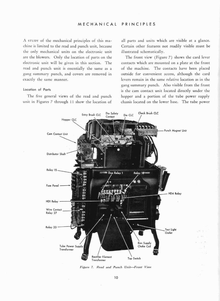
The front view (Figure 7) shows the card lever contacts which are mounted on a plate a t the front
of the machine. The contacts have been placed
ourside for convenient access, although the card
levers remain in the same relative location as in the
gang summary punch. Also visible from the front
is the cam contact unit located directly under the
hopper and a portion of the rube power supply
chassis located on the lower base. The tube power
Check Brush CLC Entry Brush CLC ::nE:" Die CLC /
Unit
Relay
Figure 7 . Read and Punch Unit-Front View
10
' M E C H . A N I C A L P R I N C I P L E S ' 11
Q Terminal Punch Magnet 80 Terminal Punch Magnet 10
Selt (Full
Common Terminal
Motor Starting / Capacitor
Connector Latch
miurn Rectifier
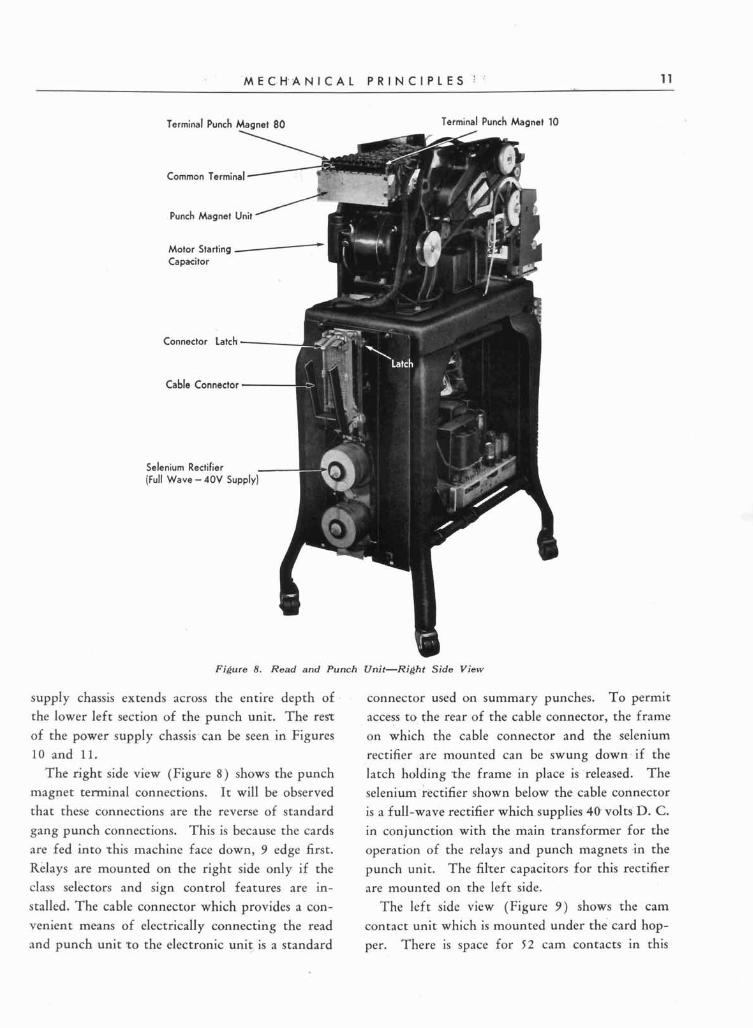
Figure 8. Read and Punch Unit-Right Side View
supply chassis extends across the entire depth of
the lower left section of the punch unit. The rest
of the power supply chassis-can be seen in Figures
10 and 11.
The right side view (Figure 8 ) shows the punch
magnet terminal connections. I t will be observed
that these connections are the reverse of standard
gang punch connections. This is because the cards are fed into rhis machine face down, 9 edge first.
connector used on summary punches. To permit
access to the rear of the cable connector, the frame
on which the cable connector and the selenium
rectifier are mounted can be swung down.if the
latch holding %he frame in place is 'released. The
selenium rectifier shown below the cable connector
is a full-wave rectifier which supplies 40 volts' D. C. in conjunction with the main transformer for the
operation of the relays and punch magnets .in the
Relays are mounted on the right side only if the punch unit. The filrer capacitors for this rectifier
class selectors and sign control features are in- are mounted on the left side.
stalled. The cable connector which provides a con- The left side view (Figure 9 ) shows the cam
venient means of electrically connecting the read contact unit which is mounted under the card hop-
and punch unit ro the electronic unit is a standard per. There is space for 52 cam contacts in this
12 T Y P E 6 0 3 E L E C T R O N I C M U L T I P L I E R
,Eccentric Shah
P1 Cam Contact
P27 Cam Contact
200 mld Capachrs I140V Supply)
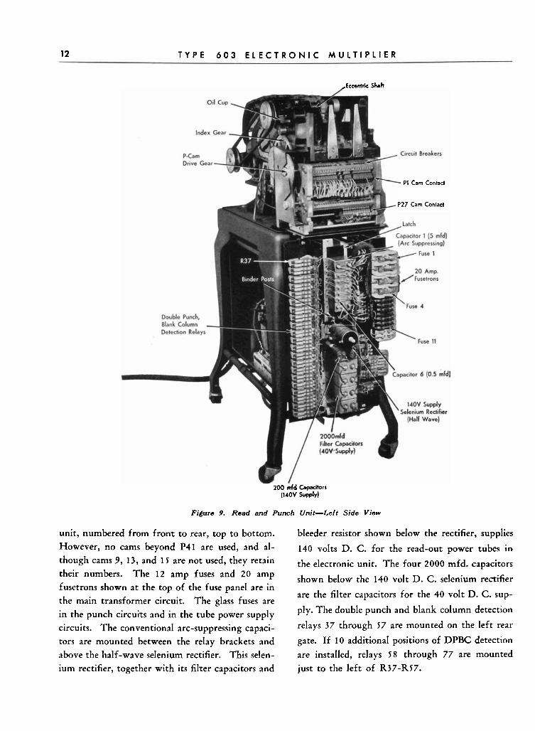
Figure 9. Reed and Punch Unit-Left Side View I unit, numbered from front to rear, top to bottom. bleeder resistor shown below the rectifier, supplies I However, no cams beyond P41 are used, and al-
though cams 9, 13, and 15 are not used, they retain
their numbers. The 12 amp fuses and 20 amp fusetrons shown at the top of the fuse panel are in
the main transformer circuit. The glass fuses are
in the punch circuits and in the tube power supply
circuits. The conventional arc-suppressing capaci-
tors are mounted between the relay brackets and
above the half-wave selenium rectifier. This selen-
ium rectifier, together with its filter capacitors and
140 volts D. C. for the read-out power tubes in
the electronic unit. The four 2000 mfd. capacitors
shown below the 140 volt D. C. selenium rectifier
are the filter capacitors for the 40 volt D. C. sup-
ply. The double punch and blank column detection
relays 37 through 57 are mounted on the left rear
gate. If 10 additional positions of DPBC detection
are installed, relays 58 through 77 are mounted
just to the left of R37-R57. a
M E C H A N I C A L P R I N C I P L E S 13
Oil Level
Crank Stud Indicator
Gear Housing \ Oil Cup
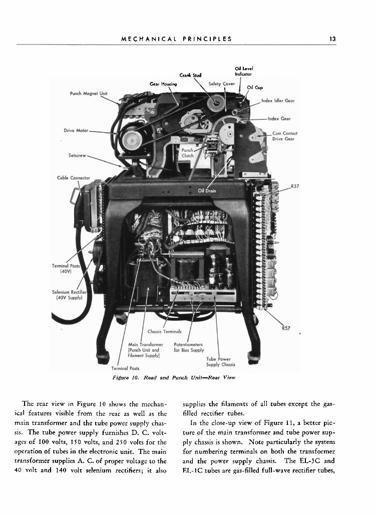
Figure 10. Read and Punch Unit-Rear View
The rear view in Figure 10 shows the mechan-
ical features visible from the rear as well as the
main transformer and the tube power supply chas-
sis. The tube power supply furnishes D. C . volt-
ages of 100 volts, 150 volrs, and 250 volts for the
operation of tubes in the electronic unit. The main
+ transformer supplies A. C. of proper voltage to the 40 volt and 140 volt selenium rectifiers; it also
supplies -the filaments of all tubes except the gas- filled rectifier tubes.
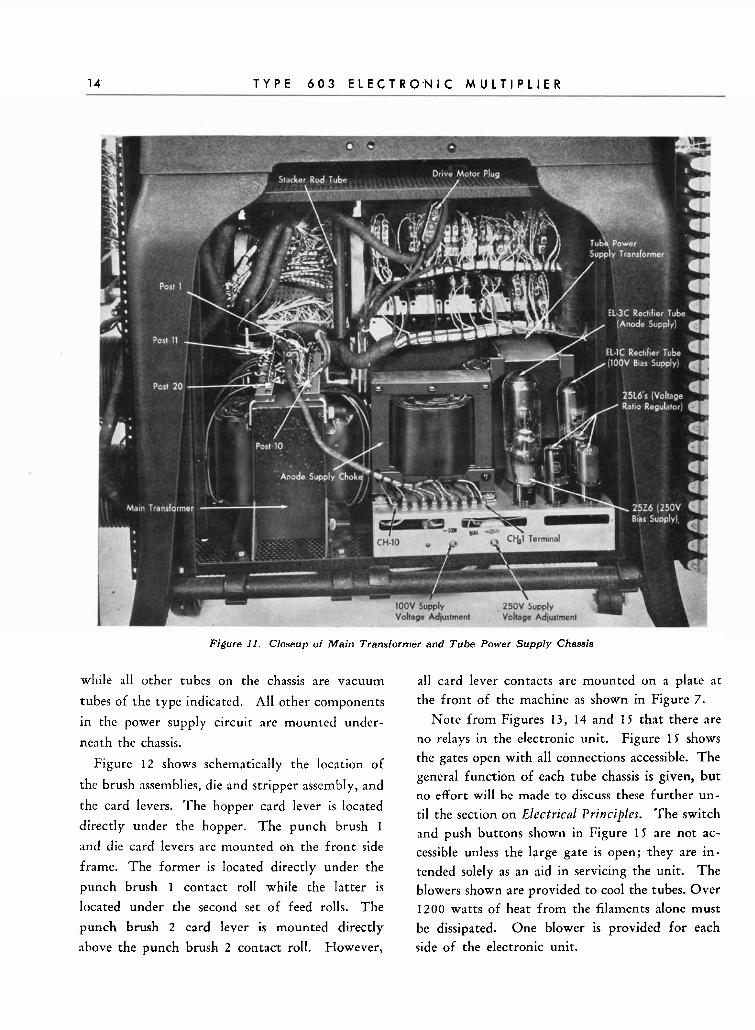
In the close-up view of Figure 11, a better pic-
ture of -the main transformer and tube power sup-
ply chassis is shown. Note particularly the system for numbering terminals on both the transformer
and the power supply chassis. The EL-3C and
EL-1C tubes are gas-filled full-wave rectifier tubes,
14 T Y P E 6 0 3 E L E C T R 0 , N I C M U L T I P L I E R
Figure 11. Closeup of Main Transformer and Tube Power Supply Chassis
while a l l other tubes on the chassis are vacuum
tubes of the type indicated. All other components
in the power supply circuit are mounted under-
neath the chassis.
Figure 12 shows schematically the location of
the brush assemblies, die and stripper assembly, and
the card levers. The hopper card lever is located
directly under the hopper. The punch brush 1
and die card levers are mounted oh the front side
frame. The former is located directly under the
punch brush I con,tact roll while the latter is
located under the second set of feed rolls. The
punch brush 2 card lever is mounted directly
above the punch brush 2 contact roll. However,
all card lever contacts are mounted on a plate at
the front of the machine as shown in Figure 7.
Note from Figures 13, 14 and 1 5 that there are no relays in the electronic unit. Figure 15 shows
the gates open with all connections accessible. The general function of each tube chassis is given, but no effort will be made to discuss these further un- til the section on Electrical Principles. The switch and push buttons shown in Figure 1 5 are not ac-
cessible unless the large gate is open; rhey are in- tended solely as an aid in servicing the unit. The
blowers shown are provided to cool the tubes. Over 1200 watts of heat from the filaments alone must
be dissipated. One blower is provided for each
side of the electronic unit.
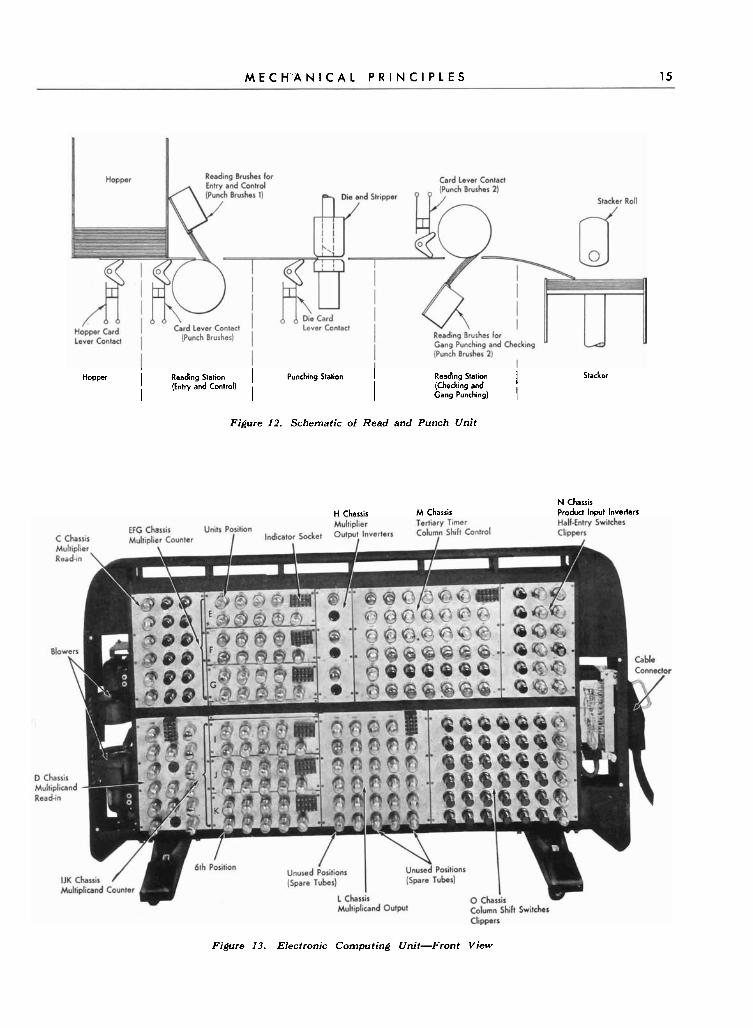
M E C H A N I C A L P R I N C I P L E S 15
Hopper i Reading Station I Punching Station I I
(Entry and Control) I I Reading Station (Checking and I Gang Punching) I
Figure 12. Schematic o f Read and Punch Unit
Stacker
H Chassis M Chassis N Chassis Product Input lnverlers
Figure 13. Electronic Computing Unit-Front View
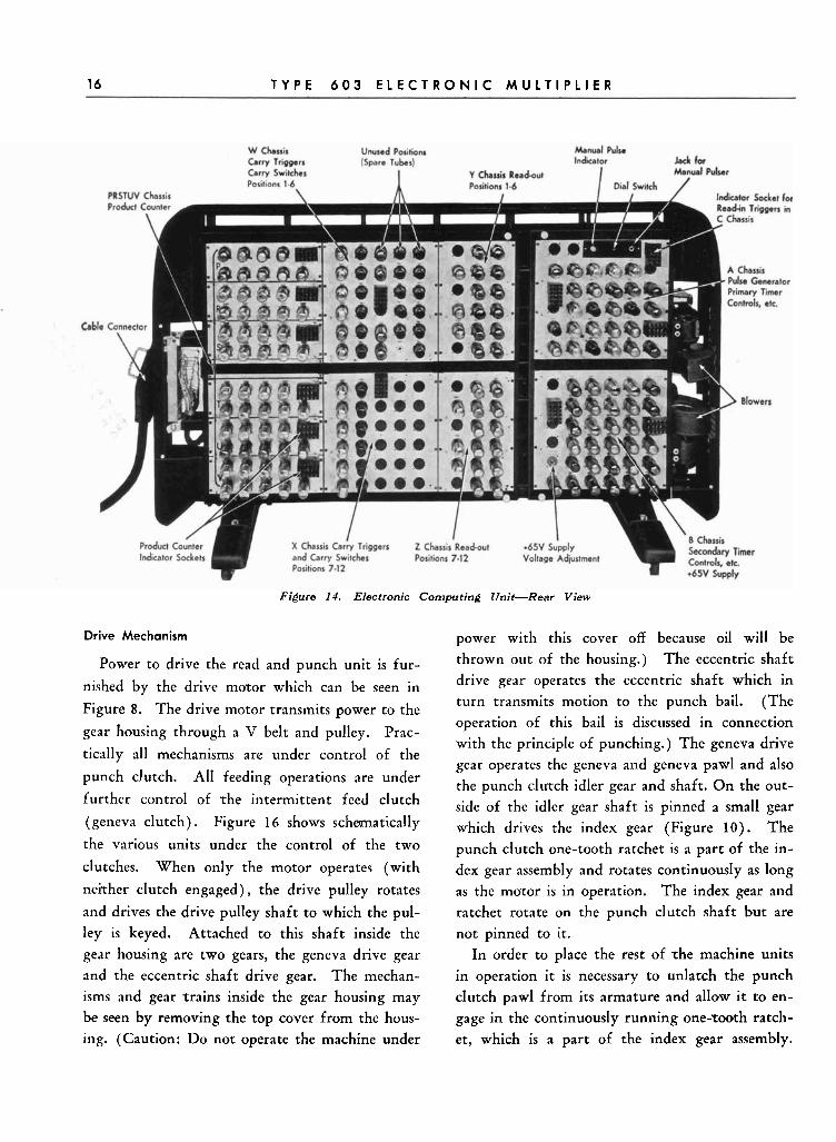
16 T Y P E 6 0 3 E L E C T R O N I C M U L T I P L I E R
Figure 14 . Electronic Computing Unit-Rear View
Drive Mechanism
Power to drive the read and punch unit is fur-
nished by the drive motor which can be seen in
Figure 8. The drive motor transmits power to the
gear housing through a V belt and pulley. Prac-
tically all mechanisms are under control of the
punch clutch. All feeding operations are under
further control of the intermittent feed clutch
(geneva clutch). Figure 16 shows schmatically
the various units under the control of the two
clutches. When only the motor operates (with
neither clutch engaged), the drive pulley rotates
and drives the drive pulley shaft to which the pul-
power with this cover off because oil will be
thrown out of the housing.) The eccentric shaft
drive gear operates the eccentric shaft which in
turn transmits motion to the punch bail. (The
operation of this bail is discussed in connection
with the principle of punching.) The geneva drive
gear operates the geneva and geneva pawl and also
the punch clutch idler gear and shaft. O n the out-
side of the idler gear shaft is pinned a small gear
which drives the index gear (Figure 1 0 ) . The
punch clutch one-tooth ratchet is a part of the in-
dex gear assembly and rotates continuously as long
as the motor is in operation. The index gear and
ratchet rotate on the ~ u n c h clutch shaft but are
ley is keyed. Attached to this shaft inside the not pinned to it.
gear housing are two gears, the geneva drive gear In order to place the rest of -the machine units
and the eccentric shaft drive gear. The mechan- in operation it is necessary to unlatch the punch
isms and gear trains inside the gear housing may clutch pawl from its armature and allow i t to en-
be seen by removing the top cover from the hous- gage in the continuously running one-~00th ratch-
ing. (Caution: Do not operate the machine under et, which is a part of the index gear assembly.
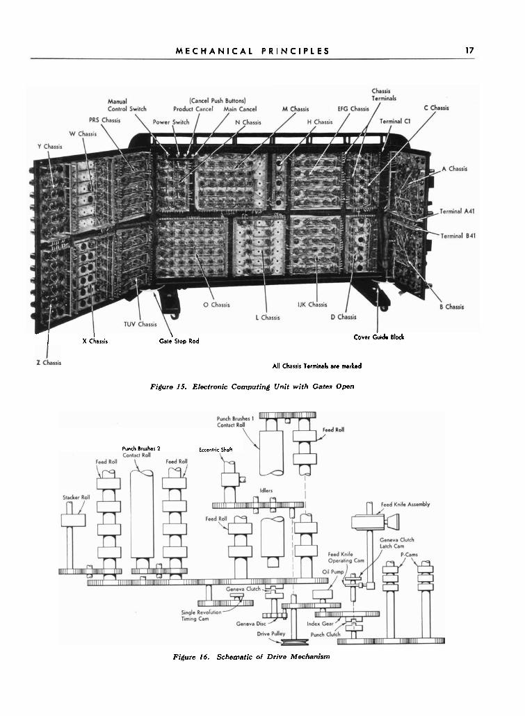
M E C H A N I C A L P R I N C I P L E S 17
- I I \ X Chassis Gate Stop Rod Cover &i& Block
All Chassis Terminals are marked
Figure 15. Electronic Computing Unit with Gates Open
Punch Brushes 2 Eccentric Shaft
Figure 16. Schematic of Drive Mechanism
When the clutch pawl engages the one-tooth
ratchet, the punch clutch shaft .turns with the
ratchet. The gear mounted on the outside end of
the punch clutch shaft in turn drives the P-cam
shaft, on which are mounted the P-cams. Within the gear housing there are two sets of comple-
mentary cams pinned to the punch clutch shaft.
One set of cams operates the feed knives and the
other set conrrols the engaging of the geneva clutch
pawl with its ratchet. The geneva ratchet is nor-
mally stationary; but when rhe geneva pawl en-
gages with it, the ratchet is driven by the geneva,
which imparts an intermittent motion TO this
ratchet. Riveted to the geneva ratchet is the
ratchet gear which serves as the drive gear for all
feed rolls, contact rolls, and the stacker roll. Since all these rolls are driven from the geneva, they all
turn intermittently. The intermirtent movement
is nccessary to have the card in a stationary posi-
tion while punching. (This is discussed in more
detail in the section on the Gerzeva Mechanis-in.) Only the upper feed rolls and the punch brush
2 contact roll are driven from the gear train
in the housing. The lower feed rolls are driven
by their corresponding upper rolls through gears
at the front of ,the machine. Also, the punch brush
1 contact roll is driven from the first upper feed
roll. The stacker roll is driven by a gear train from
the last feed roll.
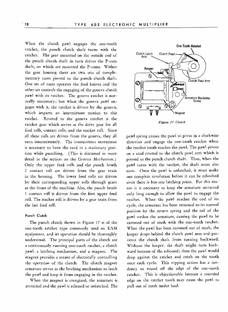
Punch Clutch
The punch clutch shown in Figure 17 is of the
one-tooth rarchet type commonly used on EAM
equipment, and its operation should be thoroughly
understood. The principal parts of the clutch are
a continuously running one-tooth ratchet, a clurch
pawl, a latching mechanism, and a magnet. The
magnet provides a means of electrically controlling
the operation of the clutch. The clutch magnet
armature serves as the latching mechanism to latch
the pawl and keep it from engaging in the ratchet.
When rhe magnet is energized, the armature is
attracted and the pawl is released or unlatched. The
One Tooth Ratchet
Figure 17. Clutch
pawl spring causes the pawl to pivot in a clockwise
direction and engage the one-tooth ratchet when
the r2tchet tooth reaches the pawl. The pawl pivots
on a stud riveted to the clutch pawl arm which is pinned to the punch clutch shaft. Thus, when the
pawl turns with the ratchet, the shaft must also
turn. Once the pawl is unlatched, it must make
one complete revolution before it can be relatched since there is but one l a ~ c h i n ~ point. For this rea-
son it is necessary to keep the armature attracted
only !ong enough to allow the pawl to engage the
ratchet. When rhe pawl reaches the end of its
cycle, the armature has been returned to its normal
position by the return spring and the tail of the
strikes the armature, causing the pawl to be
cammed out of mesh with the one-tooth ratchet.
When the pawl has been cammed out of mesh, the
keeper drops behind the clutch pawl arm and pre-
vents ,the clutch shaft from turning backward.
Without the keeper, the shaft might turn back-
ward because of the rebound; then the pawl would
drop against the ratchet and ca,tch on the tooth
once each cycle. This nipping action has a ten-
dency to round off the edge of the one-tooth
ratchet. This is objectionable because a rounded
edge on the ra~chet tooth may cause the pawl to
pull out of mesh under load.
M E C H A N I C A L P R I N C I P L E S 19
I I
of four bearing shoes held against the feed roll
shaft by compression springs.
The card also passes two sets of brushes and con- tact rolls. The brush assemblies are identical ex-
cept for minor constructional differences; each
consists of 80 individual brushes mounted in a
brush holder so that they are insulated from each other. The contact rolls are made of beryllium
copper and are geared to turn at a higher speed
than the feed rolls to provide a wiping action by
the card.
Index and Cycles
In explaining machine operations it is necessary
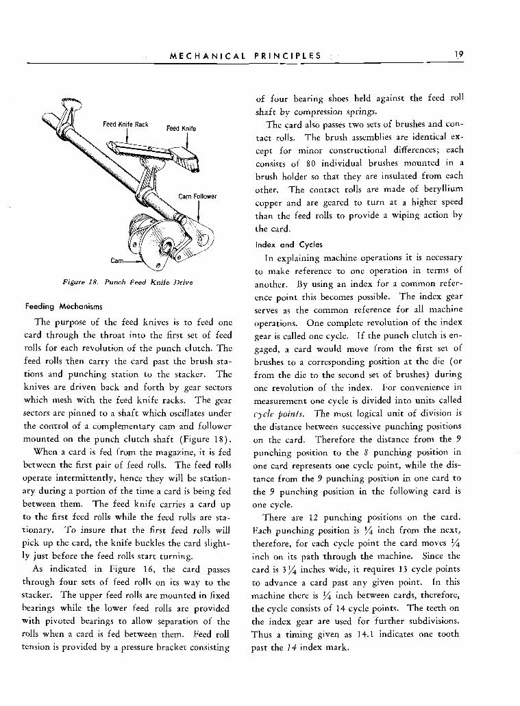
to make reference to one operation in terms of Figure 18. Punch Feed Knife Drive another. By using an index for a common refer-
ence point this becomes possible. The index gear Feeding Mechanisms serves as the common reference for all machine
The purpose of the feed knives is to feed one operations. One complete revolution of the index card through the throat into the first set of feed gear is called one cycle. If the punch clutch is en-
@ rolls for each revolution of the punch clutch. The gaged, a card would move from the first set of feed rolls rhen carry the card past the brush sta- brushes to a corresponding posirion at the die (or tions and punching station to the stacker. The from the die to the second set of brushes) during knives are driven back and forth by gear sectors one revolution of the index. For convenience in which mesh with the feed knife racks. The gear measurement one cycle is divided into units called sectors are pinned to a shaft which oscillates under cycle poifzts. The most logical unit of division is the control of a complementary cam and follower the distance between successive punching positions mounted on the punch clutch shaft (Figure 18). on the card. Therefore the distance from the 9
When a card is fed from the magazine, it is fed punching position to the 8 punching position in between the first pair of feed rolls. The feed rolls one card represents one cycle point, while the dis- operate intermittently, hence rhey will be station- tance from the 9 punching posirion in one card to ary during a portion of the time a card is being fed the 9 punching position in the following card is between them. The feed knife carries a card up one cycle. to the first feed rolls while the feed rolls are sta- There are 12 punching positions on the card. rionary. T o insure that the first feed rolls will Each punching position is j/4 inch from the next, pick up the card, the knife buckles the card slight- therefore, for each cycle point the card moves '/4 ly just before the feed rolls start turning. inch on its path rhrough the machine. Since the
As indicated in Figure 16, the card passes card is 3 '/4 inches wide, it requires 13 cycle points
through four sets of feed rolls on its way to he to advance a card past any given point. In this stacker. The upper feed rolls are mounted in fixed machine there is '/4 inch between cards, therefore, bearings while the lower feed rolls are provided the cycle consists of 14 cycle points. The teeth on with pivoted bearings to allow separation of the the index gear are used for further subdivisions. rolls when a card is fed between them. Feed roll Thus a timing given as 14.1 indicates one tooth tension is provided by a pressure bracket consisting past the 14 index mark.
20 T Y P E 6 0 3 E L E C T R O N I C M U L T I P L I E R
Geneva Mechanism
As indicated previously, the feed rolls in this machine operare intermittently to allow punching of the card. The card must not be in motion while the are being driven through the card and
withdrawn. If the card is moving, the holes will not be clean cut, but ragged and torn. Since the card musr be standing still while it is punched, then moved to a new punching position fourteen times each cycle, the motion is necessarily inter-
Gene
mittent. This intermittent mo.tion is obtained by means of a geneva mechanism.
The geneva drive gear is located just inside the gear housing and pinned to the pulley shaft. A
stud and roller fastened r o this gear operate in the slots of the driven member of the geneva gear (Figure 19).
The hub of the geneva drive gear is a cam sur- face for approximately two-thirds of its periphery.
This cam surface holds the feed rolls in a station- ary position during punching time by locking rhe geneva in position.
The geneva disc has seven deep slots and seven shallow cuts in it. The roller of the drive gear
operates in the deep cuts in the geneva disc and the cam surface rides in the shallow cuts. As the drive roller leaves the deep cut of the geneva disc,
Figure 19. Geneva Mechanism
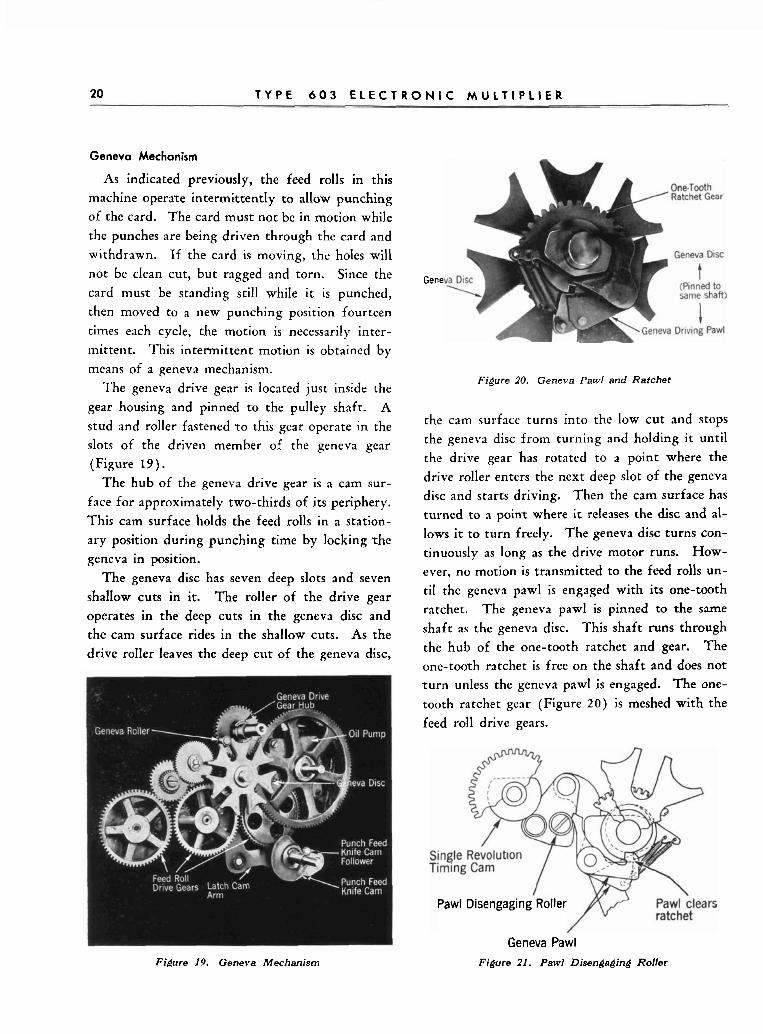
Figure 20. Geneva Pawl and Ratchet
the cam surface turns into the low cut and stops the geneva disc from turning and holding it until the drive gear has rotated to a point where the drive roller enters the next deep slot of the geneva disc and starts driving. Then the cam surface has turned to a poinr where it releases the disc and al-
lows it to turn freely. The geneva disc turns con- tinuously as long as the drive motor runs. How-
ever, no motion is transmitted to the feed rolls un-
til the geneva pawl is engaged with its one-tooth ratchet. The geneva pawl is pinned to the same
shaft as the geneva disc. This shaft runs through the hub of the one-tooth ratchet and gear. The
one-toorh ratchet is free on the shaft and does not tu rn unless the geneva pawl is engaged. The one-
tooth ratchet gear (Figure 2 0 ) is meshed with the
feed roll drive gears.
Pawl Disengaging Roller
Geneva Pawl Figure 21. Pawl Disengaging Roller
M E C H A N I C A L P R I N C I P L E S 2 1
When the punch clutch is not engaged, the gen-
eva awl rides on the surface of the one-tooth
ratchet during the greater part of the cycle. When
the pawl reaches a point opposite the single tooth,
the tail of the pawl strikes the awl disengaging
roller (Figure 2 1 ) and is cammed away from the
ratchet until it has moved past the point where
it may engage in the single tooth of the ratcher.
By cranking the machine by hand, it can be noted
how the pawl disengaging roller prevents the ge-
neva pawl from engaging. From the above, it is evident that the operation of the geneva pawl is
controlled by the pawl disengaging roller. The pawl disengaging roller is mounted on a triangular
plate (Figure 2 1 ) which is free to pivot on the
latch cam roller arm. The latch cam roller arm (Figure 2 2 ) is operated by the latch cam which
turns only when the punch clutch is engaged.
When the punch clutch is engaged, the latch cam
turns, causing the latch cam arm to rotate in a
counterclockwise direction. As the latch cam arm
rotates, the upper end moves to the left and down
allowing the pawl disengaging roller to move past
the single revolution timing cam and the geneva
pawl to engage in the one-tooth ratchet. As the cycle is completed, the larch cam causes the latch
cam arm to rotate in a clockwise direction carrying
the pawl disengaging roller to the right. The rol-
ler strikes the tail of the geneva pawl and disen-
gages the pawl from the one-tooth ratchet when
the roller is backed by the single revolution timing
cam.
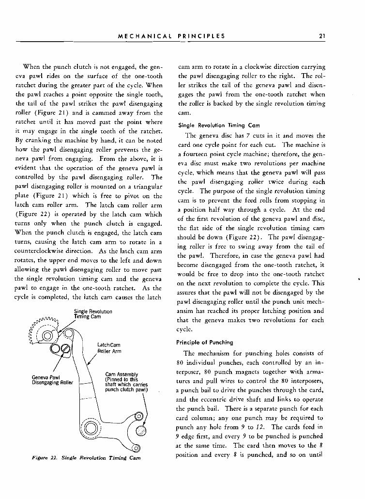
Single Revolution Timing C a m
The geneva disc has 7 cuts in it and moves the
card one cycle point for each cut. The machine is
a fourteen point cycle machine; therefore, the gen-
eva disc must make two revolutions per machine
cycle, which means that the geneva pawl will pass
the pawl disengaging roller twice during each
cycle. The purpose of the single revolution timing
cam is to prevent the feed rolls from stopping in
a position half way through a cycle. At the end
of the first revolution of the geneva pawl and disc,
the flat side of the single revolution timing cam
should be down (Figure 2 2 ) . The pawl disengag-
ing roller is free to swing away from the tail of
the pawl. Therefore, in case the geneva pawl had
become disengaged from the one-tooth ratchet, it would be free to drop into the one-tooth ratchet
on the next revolution to complete the cycle. This
assures that the pawl will not be disengaged by the
pawl disengaging roller until the punch unit mech-
ansim has reached its proper latching position and
that the geneva makes two revolutions for each
cycle.
Principle o f Punching
The mechanism for punching holes consists of
80 individual punches, each controlled by an in- /
Cam Assembly terposer, 80 punch magnets together with arma- Geneva Pawl Disengaging Roller (Pinned to this
shaft which carries tures and pull wires to control the 80 interposers,
punch clutch pawl) . a punch bail to drive the punches through the card,
and the eccentric drive shaft and links to operate L\-<j the punch bail. There is a separate punch for each
card column; any one punch may be required to
punch any hole from 9 to 12. The cards feed in , I ', '/ .___.', 9 edge first, and every 9 to be punched is punched
: 0 at the same time. The card then moves to the 8
Figure 22. Single Revolution Timing Cam position and every 8 is punched, and so on until
22 T Y P E 6 0 3 E L E C T R O N I C M U L T I P L I E R
Eccentric Shaft
R
I Magnet Pull Wire
Stripper
Die
A Figure 23. PI
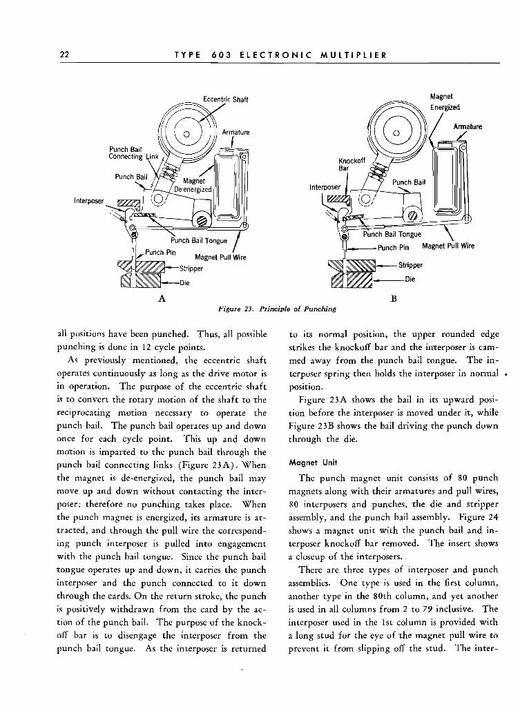
all positions have been punched. Thus, all possible ~ u n c h i n ~ is done in 12 cycle points.
As previously mentioned, the eccentric shaft
operates continuously as long as the drive motor is
in operation. The purpose of the eccentric shaft is to convert the rotary motion of the shaft to the
reciprocating motion necessary to operate the
punch bail. The punch bail operates up and down
once for each cycle point. This up and down morion is imparted to the punch bail through the
punch bail connecting links (Figure 23A). When
the magnet is de-energized, the punch bail may
move up and down without contacting the inter-
poser; therefore no punching takes place. When the punch magnet is energized, its armature is at-
tracted, and through the pull wire the correspond-
ing punch interposer is pulled into engagement
with the punch bail tongue. Since the punch bail
tongue operates up and down, it carries the punch
interposer and the punch connected to it down
through the cards. On the return stroke, the punch
is positively withdrawn from the card by the ac-
tion of the punch bail. The purpose of the knock-
off bar is to disengage the interposer from the
punch bail tongue. As the interposer is returned
Magnet
lnte
B .inciple of Punching
to its normal position, the upper rounded edge
strikes the knockoff bar and the interposer is cam-
med away from the punch bail tongue. The in-
terposer spring then holds the interposer in normal . position.
Figure 23A shows the bail in its upward posi-
tion before the interposer is moved under it, while
Figure 23B shows the bail driving the punch down
through the die.
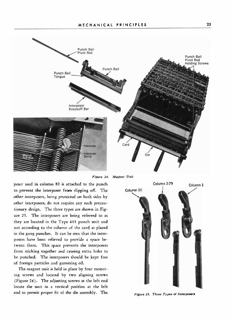
Magnet Unit
The punch magnet unit consists of 80 punch
magnets along with their armatures and pull wires,
80 interposers and punches, the die and stripper
assembly, and the punch bail assembly. Figure 24
shows a magnet unit with the punch bail and in- terposer knockoff bar removed. The insert shows
a closeup of the interposers.
There are three types of interposer and punch
assemblies. One type is used in the first column,
another type in the 80th column, and yet another
is used in all columns from 2 to 79 inclusive. The
interposer used in the 1st column is provided with
a long stud for the eye of the magnet ~ u l l wire to prevent it from slipping off the stud. The inter-
M E C H A N I C A L P R I N C I P L E S 23
Figure 24. Magnet Unit
poser used in column 80 is attached to the punch Column 2-79 Column 1
to prevent the interposer from slipping off. The
orher interposers, being protected on both sides by
other interposers, do not require any such precau-
tionary design. The three types are shown in Fig-
ure 25 . The interposers are being referred t o as
they are located in rhe Type 603 punch unit and
not according to the column of the card as placed
in the gang punches. I t can be seen that the inter-
posers have been relieved to provide a space be-
tween them. This space prevefits the interposers
from sticking together and causing extra holes to
be punched. The interposers should be kept free
of foreign particles and gumming oil.
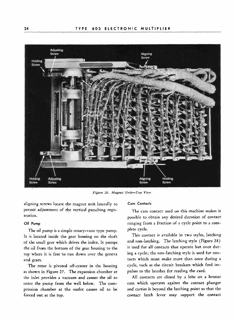
The magnet unit is held in place by four mount-
ing screws and located by two aligning screws
(Figure 2 6 ) . The adjusting screws a t the left end
locate the unit in a vertical position at the left
end to permit proper fit of the die assembly. The
Column \
Figure 25. Three Types of Interposers
24 T Y P E 6 0 3 E L E C T R O N I C M U L T I P L I E R
C
Figure 26. Magnet Unit-Top View
aligning screws locate the magnet unir laterally to Cam Contacts
permit adjustment of the vertical punching regis- The cam contact used on this machine makes it tration. possible to obtain any desired duration of contact
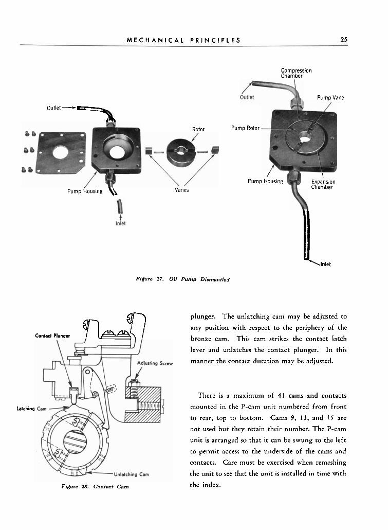
Oil Pump ranging from a fraction of a cycle point to a com-
The oil pump is a simple rotary-vane type pump. I t is located inside the gear housing on the shaft
of the small gear which drives the index. I t pumps
the oil from the bottom of the gear housing to the
top where it is free t o run down over the geneva
and gears.
The rotor is pivoted off-center in the housing
as shown in Figure 27. The expansion chamber at
the inlet provides a vacuum and causes the oil to
enter the pump from the well below. The com-
pression chamber at rhe outlet causes oil to be
forced out at the top.
plete cycle.
This contact is available in two styles, latching
and non-latching The latching style (Figure 28 )
is used for all contacts that operate bur once dur-
ing a cycle; the non-latching style is used for con-
tacts which must make more than once during a
cycle, such as the circuit breakers which feed im-
pulses to rhe brushes for reading the card.
All contacts are closed by a lobe on a bronze
cam which operates against the contact plunger
and carries it beyond the latching point so that the
conract latch lever may support the contact
M E C H A N I C A L P R I N C I P L E S 25
Outlet - =-%
Rotor Pump
Compression Chamber
Pump Vane
Latching
pump housing \\ Vanes
Contact Plunger hQ
Figure 27. Oil Pump Dismantled
Figure 28. Contact Cam
Rotor
Pump L u r i n g \ -
Expansion Chamber
li Inlet
plunger. The unlatching cam may be adjusted to
any position with respect to the periphery of the
bronze cam. This cam strikes the contact latch
lever and unlatches rhe contact plunger. In this
manner the contact duration may be adjusted.
There is a maximum of 41 cams and contacts
mounted in the P-cam unit numbered from front
to rear, rop to bottom. Cams 9, 13, and 1 F are
not used but they retain their number. The P-cam
unit is arranged so that it can be swung to the left
to permit access ro the underside of the cams and
contacts. Care must be exercised when remeshing
the unit to see that the unit is installed in time with
the index.