Embed Size (px)
Citation preview
Journal of Multidisciplinary Engineering Science and Technology (JMEST)
ISSN: 2458-9403
Vol. 3 Issue 11, November - 2016
www.jmest.org
JMESTN42351881 5975
Mechanical joining as an alternative method to resistance spot welding and riveting
Ľuboš Kaščák
Department of Computer Support of Technology Technical University of Košice
Košice, Slovakia [email protected]
Abstract— The most common methods for joining the structural steels are riveting and resistance spot welding. However, these methods require some specific time-consuming pretreatment of joined materials. In addition, when galvanized steel sheets are joined, the protective layer is destroyed which lead to decreasing of corrosion resistance and structural failure. Therefore, it is necessary to utilize the other joining methods. The paper deals with the assessment of the possibilities of mechanical joining as an alternative method to resistance spot welding and riveting. Riveted joints, resistance spot welded joints and clinched joints are permanent joints, which means, that those joints cannot be disassembled without damaging the assembled parts. Hot-dip galvanized structural steel sheet S250GD with the thickness of 1.5 mm and 2.5 mm were used for the experiments. Mechanical joining, especially clinching, is a combination of drawing and forming. The research is focused on the evaluation of joints' properties using shearing test and metallographic observation of material structure.
Keywords—clinching; mechanical joining; riveting; resistance welding; tensile test; metallography
I. INTRODUCTION
Joining techniques in the industry are predominantly driven by advances in materials, working with dissimilar materials and the call for increased automation. Riveting machines apply rivets to materials in a wide variety of configurations, from manually operated riveting guns to multi-head automated electrical, hydraulic or pneumatic riveting tools. There are three main types of riveting machinery - compression riveting, non-impact riveting and impact riveting [1].
During the last few decades, rapid development of welding technology has considerably reduced the sphere of application of riveted joints. Today, riveted joints have almost been replaced by welded joints [2].
Resistance spot welding is one of the oldest of the electric welding processes in use by industry today. This joining method is accomplished by passing an
electrical current through joined sheets via electrodes. The heat induced by the electrical current creates a molten nugget. The molten nugget then solidifies to create a bond between the sheets [3,4] After spot welding, important changes occur in mechanical and metallurgical properties of the spot welded areas and heat affected zones. The investigation of these changes is very important for the strength of welded joints [5,6]. When welding galvanized steel sheets, it is required to use greater welding current and electrode pressure as well as longer welding time due to the shunting effect of zinc coating compared to welding of uncoated steel sheets of the same thickness and quality [7,8]. The wear of welding electrode tips becomes large because of the lower electricity resistance and melting temperature of protective layer [9].
Both riveting as well as resistance spot welding destroyed protective coating (zinc coating) on the joined steel sheets, which causes the decreasing of corrosion resistance. Another disadvantage is the need of drilling holes in the steel sheets (riveting) and consistent surface cleaning of steel sheets before joining (resistance spot welding). Therefore, it is important to utilize other joining methods such as mechanical joining – clinching. Clinching can overcome the disadvantages of resistance spot welding and riveting.
Clinching as most used method of mechanical joining is a metalworking process which can connect steel sheets effectively without any splashes, flashes or harmful light. Moreover, this joining method can be used for joining the coated sheets with no damage to the surface. The sheets are joined by local hemming with a punch and die. It can be used in automotive, building or electrical industry [10,11].
II. PRINCIPLE OF MECHANICAL JOINING
Clinching is a high-speed joining technique, which uses a special punch and die. The joined sheets are formed by the punch and die to create the mechanical interlock between the lower and the upper sheets. The strength of the joined sheets is determined by the amount of the formed interlock. These sheets are joined by way being hooked on the interlock, which is created around the punch corners, whereas the thickness of upper sheet decreases. It is necessary to
Journal of Multidisciplinary Engineering Science and Technology (JMEST)
ISSN: 2458-9403
Vol. 3 Issue 11, November - 2016
www.jmest.org
JMESTN42351881 5976
obtain the critical wall thickness of the upper sheet around the punch corner without any fracture. The fracture of the joined sheets can lead to corrosion of the parts [12-14].
Fig. 1. Principle of mechanical joining – clinching [4]
Single-step clinching process (Fig. 1) can be described as [4]:
Step 1: The punch and blank holder move downward, the workpieces are clamped and fixed by spring force of blank holder.
Step 2: By action of the punch the material flows into the bottom die cavity forming a cup. The process parameters and dimensions of the punch and die are finely tuned to the sheet thicknesses of the work pieces. This insures that no material is laterally drawn into the joint from surrounding area.
Step 3: Finally, the thickness of the cup's bottom is reduced by upsetting and the material forced into the die groove and in lateral direction, forming the necessary undercut.
Step 4: After reaching a preset maximum force (force control) or a preset displacement (stroke controlled), the punch is retracted and the clamping force relieved. The joint connection requires no finishing.
III. MATERIALS AND EXPERIMENTS
The material for the joining was the hot-dip galvanized construction steel sheet S250GD with the thickness of a0 = 1.5 mm and 2.5 mm, produced by U.S. Steel Košice, Ltd. The basic mechanical properties (Re – yield strength, Rm – ultimate tensile strength, A80 – elongation) and chemical composition of the steel sheet is shown in Table I. and Table II.
TABLE I. MECHANICAL PROPERTIES OF JOINED STEELS
Re [MPa] Rm [MPa] A80 [%]
248 337 19
TABLE II. CHEMICAL COMPOSITION OF JOINED STEELS IN WT [%]
C Mn P S Si
0,18 1,54 0,06 0,002 0,51
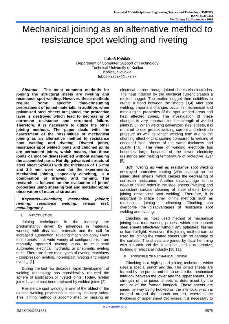
The typical ferrite-pearlite structure of the S250GD steel sheet is shown in Fig. 2.
Fig. 2. Structure of S250GD steel sheet
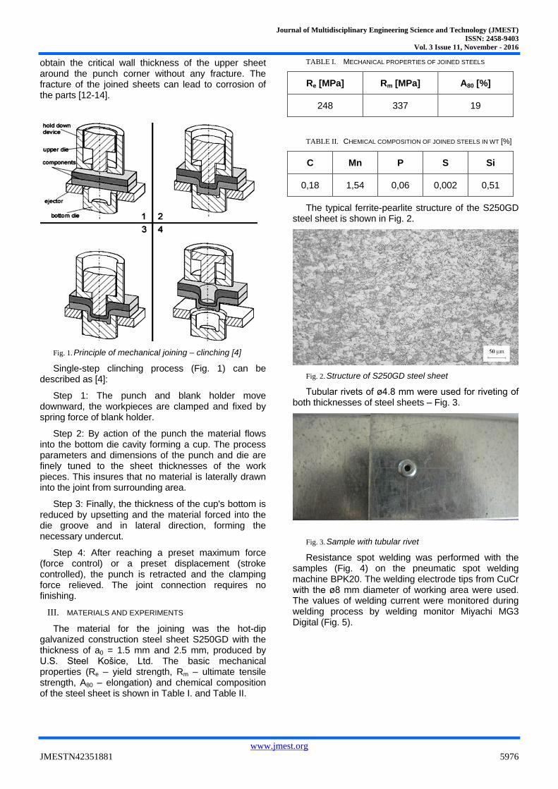
Tubular rivets of ø4.8 mm were used for riveting of both thicknesses of steel sheets – Fig. 3.
Fig. 3. Sample with tubular rivet
Resistance spot welding was performed with the samples (Fig. 4) on the pneumatic spot welding machine BPK20. The welding electrode tips from CuCr with the ø8 mm diameter of working area were used. The values of welding current were monitored during welding process by welding monitor Miyachi MG3 Digital (Fig. 5).
Journal of Multidisciplinary Engineering Science and Technology (JMEST)
ISSN: 2458-9403
Vol. 3 Issue 11, November - 2016
www.jmest.org
JMESTN42351881 5977
Fig. 4. Samples with spot weld: (a)1.5 mm sheetsand (b) 2.5 mm sheets
Fig. 5. Welding monitor
The parameters of resistance spot welding used for joining of both steel sheets are shown in Table III. The welding parameters were determined according to the recommended welding parameters by IIW - International Institute of Welding, adapted to the used welding machines.
TABLE III. PARAMETERS OF RESISTANCE SPOT WELDING
Welding
Paramters
Sheet thickness a0 [mm]
1.5 2.5
Pressing force Fz [kN] 4 6
Welding time T [per.] 13 17
Welding current I [kA] 7 9
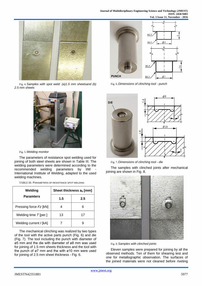
The mechanical clinching was realized by two types of the tool with the active parts punch (Fig. 6) and die (Fig. 7). The tool including the punch with diameter of ø5 mm and the die with diameter of ø8 mm was used for joining of 1.5 mm sheets thickness and the tool with the punch of ø7 mm and the with ø10 mm were used for joining of 2.5 mm sheet thickness - Fig. 6.
Fig. 6. Dimensions of clinching tool - punch
Fig. 7. Dimensions of clinching tool - die
The samples with clinched joints after mechanical joining are shown in Fig. 8.
Fig. 8. Samples with clinched joints
Eleven samples were prepared for joining by all the observed methods. Ten of them for shearing test and one for metallographic observation. The surfaces of the joined materials were not cleaned before riveting
Journal of Multidisciplinary Engineering Science and Technology (JMEST)
ISSN: 2458-9403
Vol. 3 Issue 11, November - 2016
www.jmest.org
JMESTN42351881 5978
and clinching. The surfaces of the sheet for resistance spot welding were degreased in concentrated CH3COCH3.
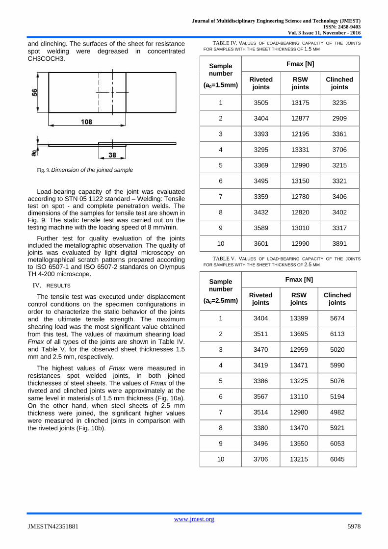
Fig. 9. Dimension of the joined sample
Load-bearing capacity of the joint was evaluated according to STN 05 1122 standard – Welding: Tensile test on spot - and complete penetration welds. The dimensions of the samples for tensile test are shown in Fig. 9. The static tensile test was carried out on the testing machine with the loading speed of 8 mm/min.
Further test for quality evaluation of the joints included the metallographic observation. The quality of joints was evaluated by light digital microscopy on metallographical scratch patterns prepared according to ISO 6507-1 and ISO 6507-2 standards on Olympus TH 4-200 microscope.
IV. RESULTS
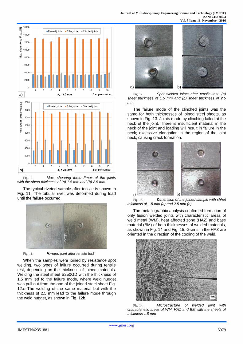
The tensile test was executed under displacement control conditions on the specimen configurations in order to characterize the static behavior of the joints and the ultimate tensile strength. The maximum shearing load was the most significant value obtained from this test. The values of maximum shearing load Fmax of all types of the joints are shown in Table IV. and Table V. for the observed sheet thicknesses 1.5 mm and 2.5 mm, respectively.
The highest values of Fmax were measured in resistances spot welded joints, in both joined thicknesses of steel sheets. The values of Fmax of the riveted and clinched joints were approximately at the same level in materials of 1.5 mm thickness (Fig. 10a). On the other hand, when steel sheets of 2.5 mm thickness were joined, the significant higher values were measured in clinched joints in comparison with the riveted joints (Fig. 10b).
TABLE IV. VALUES OF LOAD-BEARING CAPACITY OF THE JOINTS
FOR SAMPLES WITH THE SHEET THICKNESS OF 1.5 MM
Sample number
(a0=1.5mm)
Fmax [N]
Riveted joints
RSW joints
Clinched joints
1 3505 13175 3235
2 3404 12877 2909
3 3393 12195 3361
4 3295 13331 3706
5 3369 12990 3215
6 3495 13150 3321
7 3359 12780 3406
8 3432 12820 3402
9 3589 13010 3317
10 3601 12990 3891
TABLE V. VALUES OF LOAD-BEARING CAPACITY OF THE JOINTS
FOR SAMPLES WITH THE SHEET THICKNESS OF 2.5 MM
Sample number
(a0=2.5mm)
Fmax [N]
Riveted joints
RSW joints
Clinched joints
1 3404 13399 5674
2 3511 13695 6113
3 3470 12959 5020
4 3419 13471 5990
5 3386 13225 5076
6 3567 13110 5194
7 3514 12980 4982
8 3380 13470 5921
9 3496 13550 6053
10 3706 13215 6045
Journal of Multidisciplinary Engineering Science and Technology (JMEST)
ISSN: 2458-9403
Vol. 3 Issue 11, November - 2016
www.jmest.org
JMESTN42351881 5979
Fig. 10. Max. shearing force Fmax of the joints with the sheet thickness of (a) 1.5 mm and (b) 2.5 mm
The typical riveted sample after tensile is shown in Fig. 11. The tubular rivet was deformed during load until the failure occurred.
Fig. 11. Riveted joint after tensile test
When the samples were joined by resistance spot welding, two types of failure occurred during tensile test, depending on the thickness of joined materials. Welding the steel sheet S250GD with the thickness of 1.5 mm led to the failure mode, where weld nugget was pull out from the one of the joined steel sheet Fig. 12a. The welding of the same material but with the thickness of 2.5 mm lead to the failure mode through the weld nugget, as shown in Fig. 12b.
a) b)
Fig. 12. Spot welded joints after tensile test: (a) sheet thickness of 1.5 mm and (b) sheet thickness of 2.5 mm
The failure mode of the clinched joints was the same for both thicknesses of joined steel sheets, as shown in Fig. 13. Joints made by clinching failed at the neck of the joint. There is insufficient material in the neck of the joint and loading will result in failure in the neck; excessive elongation in the region of the joint neck, causing crack formation.
a) b)
Fig. 13. Dimension of the joined sample with shhet thickness of 1.5 mm (a) and 2.5 mm (b)
The metallographic analysis confirmed formation of only fusion welded joints with characteristic areas of weld metal (WM), heat affected zone (HAZ) and base material (BM) of both thicknesses of welded materials, as shown in Fig. 14 and Fig. 15. Grains in the HAZ are oriented in the direction of the cooling of the weld.
Fig. 14. Microstructure of welded joint with characteristic areas of WM, HAZ and BM with the sheets of thickness 1.5 mm
Journal of Multidisciplinary Engineering Science and Technology (JMEST)
ISSN: 2458-9403
Vol. 3 Issue 11, November - 2016
www.jmest.org
JMESTN42351881 5980
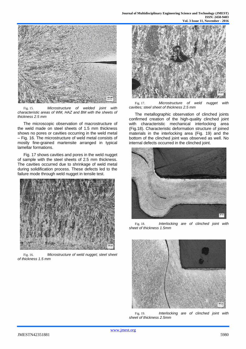
Fig. 15. Microstructure of welded joint with characteristic areas of WM, HAZ and BM with the sheets of thickness 2.5 mm
The microscopic observation of macrostructure of the weld made on steel sheets of 1.5 mm thickness shows no pores or cavities occurring in the weld metal – Fig. 16. The microstructure of weld metal consists of mostly fine-grained martensite arranged in typical lamellar formations.
Fig. 17 shows cavities and pores in the weld nugget of sample with the steel sheets of 2.5 mm thickness. The cavities occurred due to shrinkage of weld metal during solidification process. These defects led to the failure mode through weld nugget in tensile test.
Fig. 16. Microstructure of weld nugget; steel sheet of thickness 1.5 mm
Fig. 17. Microstructure of weld nugget with cavities; steel sheet of thickness 2.5 mm
The metallographic observation of clinched joints confirmed creation of the high-quality clinched joint with characteristic mechanical interlocking area (Fig.18). Characteristic deformation structure of joined materials in the interlocking area (Fig. 19) and the bottom of the clinched joint was observed as well. No internal defects occurred in the clinched joint.
Fig. 18. Interlocking are of clinched joint with sheet of thickness 1.5mm
Fig. 19. Interlocking are of clinched joint with sheet of thickness 2.5mm
Journal of Multidisciplinary Engineering Science and Technology (JMEST)
ISSN: 2458-9403
Vol. 3 Issue 11, November - 2016
www.jmest.org
JMESTN42351881 5981
V. CONCLUSION
Joining of metallic sheets is fundamental in the manufacturing of thin-walled structures. Mechanical clinching processes have become more and more popular during the last decades as the plastic press joining method in sheet metal construction assembly. Clinching resembles a sheet forming operation. A fundamental difference of clinching, in relation to traditional sheet metal forming, is that there is a forging of the sheets between the punch and the die at the bottom of the joint. The method of clinching is suitable for joining the tested materials.
Resulting from the obtained values, the maximum values of load-bearing capacity were measured in the resistance spot welded samples, in both thickness of the joined materials. The values of load-bearing capacity of riveted joints and clinched joints were approximately at the same level in joining the materials of thickness 1.5 mm. On the other hand, in joining materials of thickness 2.5 mm, clinched joint reached higher load-bearing capacity values than riveted joints. The riveted joints reached an average of 58% of load-bearing capacity of clinched joints.
In terms of load-bearing capacity, the resistance spot welding appears to be the best method of joining of observed steel sheets. However, when using riveting and clinching, it is not necessary to clean the surface of the joined materials. In comparison to resistance spot welding, utilizing the clinching as cold joining method significantly reduces the time required for joining process, consumes less power and doesn’t destroy surface protective layer. The use of the clinching in comparison to riveting significantly reduces the time required for the joining of the materials as well, since it is unnecessary to drill holes for rivets.
ACKNOWLEDGMENT
Author IS grateful for the support of experimental works by project VEGA No. 1/0396/11- Research and optimization of evaluation methods of strength and plastic properties of thin tinplates.
REFERENCES
[1] A. Chrysanthou and X. Sun, Self-piercing riveting, Woodhead Publishing: Cambridge, 2014.
[2] V.B. Bhandari, Design of Machine Elements, 3rd ed. Tata McGraw-Hill: New Delhi, 2010.
[3] P.S. Wei and T.H. Wu, “Electrical contact resistance effect on resistance spot welding”, International Journal of Heat and Mass Transfer, vol. 55, 2012, pp. 3316-3324.
[4] Ľ. Kaščák, J. Mucha, J. Slota and E. Spišák, Application of modern joining methods in car production, Oficyna Wydawnicza Politechniki Rzeszowskiej: Rzeszów, 2013.
[5] Ľ. Kaščák and E. Spišák, “Effect of welding parameters on the quality of spot welds combining AHSS steel and HSLA steel”, Key engineering Materials, vol. 586, 2014, pp. 162-165.
[6] I. Sevim, “Effect of hardness to fracture toughness for spot welded steel sheets”, Materials and Design, vol. 27, 2006, pp. 21-30.
[7] M. Lifang, Y. Jiming, Y. Dongbing, L. Jinwu and C. Genyu, “Comparative study on CO2 laser overlap welding and resistance spot welding for galvanized steel”, Materials and Design, vol. 40, 2012, pp. 433-442.
[8] H. Zhang and J. Senkara, Resistance welding: Fundamentals and Applications, Taylor and Francis: New York, 2006.
[9] X.Q. Zhang, G.L. Chen, Y.S. Zhang, “Characteristics of electrode wear in resis-tance spot welding dual-phase steels”, Materials and Design, vol. 29, 2008, pp. 279–283.
[10] T. Jiang, Z.X. Liu, and P.C. Wang, “Effect of aluminum pre-straining on strength ofclinched galvanized SAE1004 steel-to-AA6111-T4 aluminum”, Journal of Materials Processing Technology, vol. 215, 2015, pp. 193–204.
[11] C. Chen, S. Zhao, M. Cui, X. Han and S. Fan, “Mechanical properties of the two-steps clinched joints with a clinch-rivet”, Journal of Materials Processing Technology, vol. 237, 2016, pp. 361–370.
[12] J. Mucha, Ľ. Kaščák and E. Spišák, “Joining the car-body sheets using clinching process with various thickness and mechanical property arrangements”, Archives of civil and mechanical engineering, vol. 11, 2011, pp. 135-148.
[13] Y. Abe, T. Kato, K. M and S. Nishino, “Mechanical clinching of ultra-high strength steel sheets and strength of joints”, Journal of Materials Processing Technology, vol. 214, 2014, pp. 2112–2118.
[14] C.J. Lee, J.Y. Kim, S.K. Lee, D.C. Ko and B.M. Kim, “Parametric study on mechanical clinching process for joining aluminum alloy and high-strength steel sheets”, Journal of Mechanical Science and Technology, vol. 24, 2010, pp. 123-126.