Embed Size (px)
Citation preview
www.matrixtsl.comCopyright © 2016 Matrix Technology Solutions Limited 37
Mechanical engineering
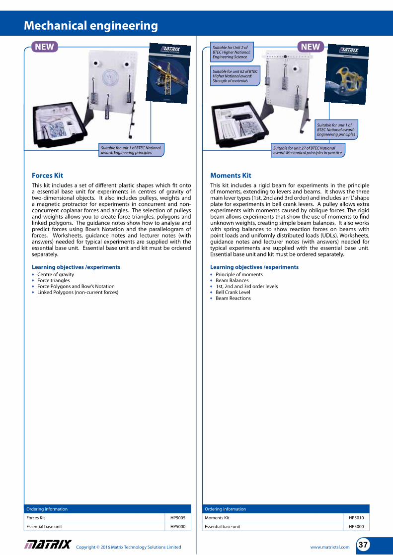
Forces Kit
This kit includes a set of diff erent plastic shapes which fi t onto a essential base unit for experiments in centres of gravity of two-dimensional objects. It also includes pulleys, weights and a magnetic protractor for experiments in concurrent and non-concurrent coplanar forces and angles. The selection of pulleys and weights allows you to create force triangles, polygons and linked polygons. The guidance notes show how to analyse and predict forces using Bow’s Notation and the parallelogram of forces. Worksheets, guidance notes and lecturer notes (with answers) needed for typical experiments are supplied with the essential base unit. Essential base unit and kit must be ordered separately.
Learning objectives /experiments
Centre of gravity Force triangles Force Polygons and Bow’s Notation Linked Polygons (non-current forces)
Ordering information
Forces Kit HP5005
Essential base unit HP5000
Ordering information
Moments Kit HP5010
Essential base unit HP5000
Moments Kit
This kit includes a rigid beam for experiments in the principle of moments, extending to levers and beams. It shows the three main lever types (1st, 2nd and 3rd order) and includes an ‘L’ shape plate for experiments in bell crank levers. A pulley allows extra experiments with moments caused by oblique forces. The rigid beam allows experiments that show the use of moments to fi nd unknown weights, creating simple beam balances. It also works with spring balances to show reaction forces on beams with point loads and uniformly distributed loads (UDLs). Worksheets, guidance notes and lecturer notes (with answers) needed for typical experiments are supplied with the essential base unit. Essential base unit and kit must be ordered separately.
Learning objectives /experiments
Principle of moments Beam Balances 1st, 2nd and 3rd order levels Bell Crank Level Beam Reactions
Suitable for Unit 2 of BTEC Higher National: Engineering Science
Suitable for unit 1 of BTEC National award: Engineering principles
Suitable for unit 62 of BTEC Higher National award: Strength of materials
Suitable for unit 27 of BTEC National award: Mechanical principles in practice
Suitable for unit 1 of BTEC National award: Engineering principles
Copyright © 2016 Matrix Technology Solutions Limited www.matrixtsl.com38
Mechanical engineering
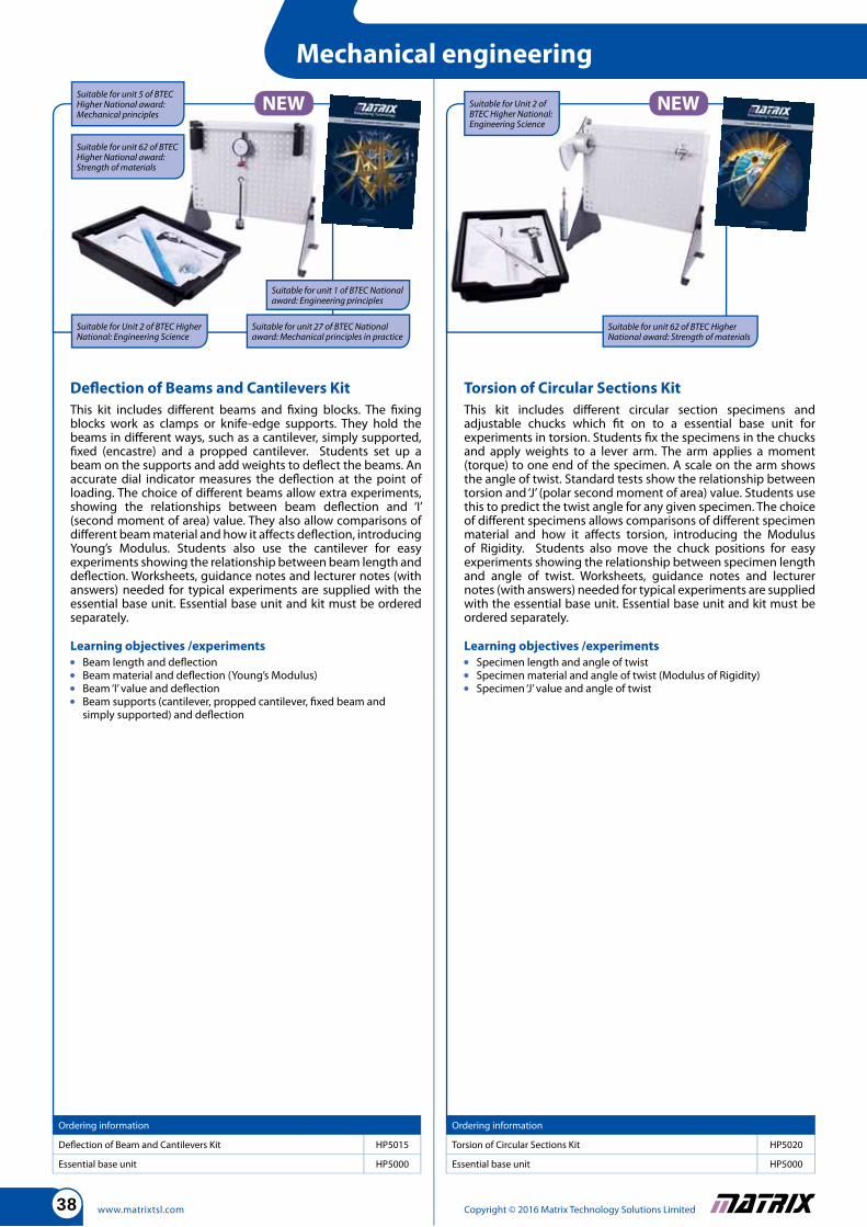
Defl ection of Beams and Cantilevers Kit
This kit includes diff erent beams and fi xing blocks. The fi xing blocks work as clamps or knife-edge supports. They hold the beams in diff erent ways, such as a cantilever, simply supported, fi xed (encastre) and a propped cantilever. Students set up a beam on the supports and add weights to defl ect the beams. An accurate dial indicator measures the defl ection at the point of loading. The choice of diff erent beams allow extra experiments, showing the relationships between beam defl ection and ‘I’ (second moment of area) value. They also allow comparisons of diff erent beam material and how it aff ects defl ection, introducing Young’s Modulus. Students also use the cantilever for easy experiments showing the relationship between beam length and defl ection. Worksheets, guidance notes and lecturer notes (with answers) needed for typical experiments are supplied with the essential base unit. Essential base unit and kit must be ordered separately.
Learning objectives /experiments
Beam length and defl ection Beam material and defl ection (Young’s Modulus) Beam ‘I’ value and defl ection Beam supports (cantilever, propped cantilever, fi xed beam and
simply supported) and defl ection
Ordering information
Defl ection of Beam and Cantilevers Kit HP5015
Essential base unit HP5000
Ordering information
Torsion of Circular Sections Kit HP5020
Essential base unit HP5000
Torsion of Circular Sections Kit
This kit includes diff erent circular section specimens and adjustable chucks which fi t on to a essential base unit for experiments in torsion. Students fi x the specimens in the chucks and apply weights to a lever arm. The arm applies a moment (torque) to one end of the specimen. A scale on the arm shows the angle of twist. Standard tests show the relationship between torsion and ‘J’ (polar second moment of area) value. Students use this to predict the twist angle for any given specimen. The choice of diff erent specimens allows comparisons of diff erent specimen material and how it aff ects torsion, introducing the Modulus of Rigidity. Students also move the chuck positions for easy experiments showing the relationship between specimen length and angle of twist. Worksheets, guidance notes and lecturer notes (with answers) needed for typical experiments are supplied with the essential base unit. Essential base unit and kit must be ordered separately.
Learning objectives /experiments
Specimen length and angle of twist Specimen material and angle of twist (Modulus of Rigidity) Specimen ‘J’ value and angle of twist
Suitable for Unit 2 of BTEC Higher National: Engineering Science
Suitable for unit 1 of BTEC National award: Engineering principles
Suitable for Unit 2 of BTEC Higher National: Engineering Science
Suitable for unit 27 of BTEC National award: Mechanical principles in practice
Suitable for unit 62 of BTEC Higher National award: Strength of materials
Suitable for unit 5 of BTEC Higher National award: Mechanical principles
Suitable for unit 62 of BTEC Higher National award: Strength of materials
www.matrixtsl.comCopyright © 2016 Matrix Technology Solutions Limited 39
Mechanical engineering
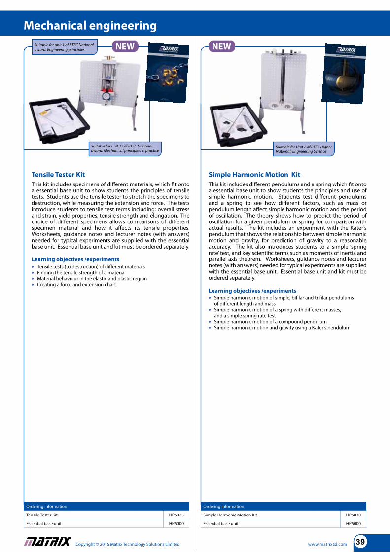
Tensile Tester Kit
This kit includes specimens of diff erent materials, which fi t onto a essential base unit to show students the principles of tensile tests. Students use the tensile tester to stretch the specimens to destruction, while measuring the extension and force. The tests introduce students to tensile test terms including: overall stress and strain, yield properties, tensile strength and elongation. The choice of diff erent specimens allows comparisons of diff erent specimen material and how it aff ects its tensile properties. Worksheets, guidance notes and lecturer notes (with answers) needed for typical experiments are supplied with the essential base unit. Essential base unit and kit must be ordered separately.
Learning objectives /experiments
Tensile tests (to destruction) of diff erent materials Finding the tensile strength of a material Material behaviour in the elastic and plastic region Creating a force and extension chart
Ordering information
Tensile Tester Kit HP5025
Essential base unit HP5000
Ordering information
Simple Harmonic Motion Kit HP5030
Essential base unit HP5000
Simple Harmonic Motion Kit
This kit includes diff erent pendulums and a spring which fi t onto a essential base unit to show students the principles and use of simple harmonic motion. Students test diff erent pendulums and a spring to see how diff erent factors, such as mass or pendulum length aff ect simple harmonic motion and the period of oscillation. The theory shows how to predict the period of oscillation for a given pendulum or spring for comparison with actual results. The kit includes an experiment with the Kater’s pendulum that shows the relationship between simple harmonic motion and gravity, for prediction of gravity to a reasonable accuracy. The kit also introduces students to a simple ‘spring rate’ test, and key scientifi c terms such as moments of inertia and parallel axis theorem. Worksheets, guidance notes and lecturer notes (with answers) needed for typical experiments are supplied with the essential base unit. Essential base unit and kit must be ordered separately.
Learning objectives /experiments
Simple harmonic motion of simple, bifi lar and trifi lar pendulums of diff erent length and mass Simple harmonic motion of a spring with diff erent masses,
and a simple spring rate test Simple harmonic motion of a compound pendulum Simple harmonic motion and gravity using a Kater’s pendulum
Suitable for Unit 2 of BTEC Higher National: Engineering Science
Suitable for unit 27 of BTEC National award: Mechanical principles in practice
Suitable for unit 1 of BTEC National award: Engineering principles
Copyright © 2016 Matrix Technology Solutions Limited www.matrixtsl.com40
Potential and kinetic energy kit
www.matrixtsl.com Copyright © 2015 Matrix Technology Solutions Ltd
Simplifying Technology
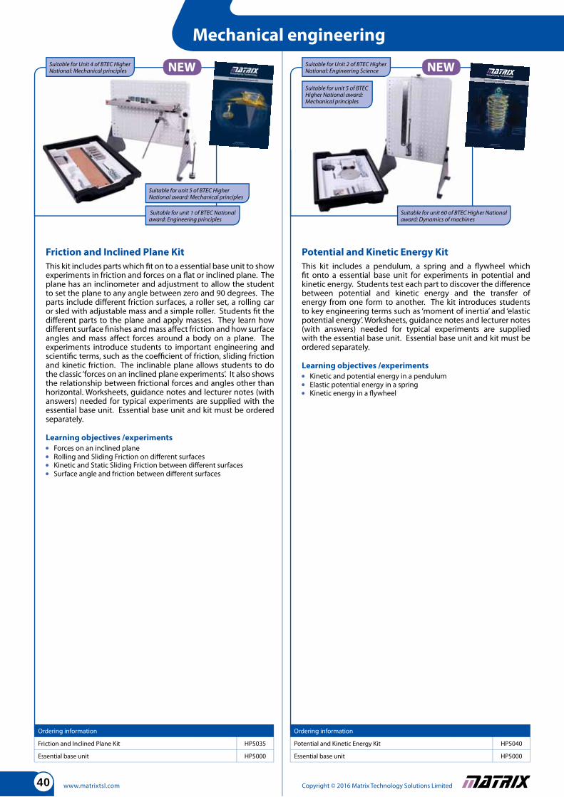
Friction and Inclined Plane Kit
This kit includes parts which fi t on to a essential base unit to show experiments in friction and forces on a fl at or inclined plane. The plane has an inclinometer and adjustment to allow the student to set the plane to any angle between zero and 90 degrees. The parts include diff erent friction surfaces, a roller set, a rolling car or sled with adjustable mass and a simple roller. Students fi t the diff erent parts to the plane and apply masses. They learn how diff erent surface fi nishes and mass aff ect friction and how surface angles and mass aff ect forces around a body on a plane. The experiments introduce students to important engineering and scientifi c terms, such as the coeffi cient of friction, sliding friction and kinetic friction. The inclinable plane allows students to do the classic ‘forces on an inclined plane experiments’. It also shows the relationship between frictional forces and angles other than horizontal. Worksheets, guidance notes and lecturer notes (with answers) needed for typical experiments are supplied with the essential base unit. Essential base unit and kit must be ordered separately.
Learning objectives /experiments
Forces on an inclined plane Rolling and Sliding Friction on diff erent surfaces Kinetic and Static Sliding Friction between diff erent surfaces Surface angle and friction between diff erent surfaces
Ordering information
Friction and Inclined Plane Kit HP5035
Essential base unit HP5000
Ordering information
Potential and Kinetic Energy Kit HP5040
Essential base unit HP5000
Potential and Kinetic Energy Kit
This kit includes a pendulum, a spring and a fl ywheel which fi t onto a essential base unit for experiments in potential and kinetic energy. Students test each part to discover the diff erence between potential and kinetic energy and the transfer of energy from one form to another. The kit introduces students to key engineering terms such as ‘moment of inertia’ and ‘elastic potential energy’. Worksheets, guidance notes and lecturer notes (with answers) needed for typical experiments are supplied with the essential base unit. Essential base unit and kit must be ordered separately.
Learning objectives /experiments
Kinetic and potential energy in a pendulum Elastic potential energy in a spring Kinetic energy in a fl ywheel
Mechanical engineering
Suitable for Unit 4 of BTEC Higher National: Mechanical principles
Suitable for Unit 2 of BTEC Higher National: Engineering Science
Suitable for unit 5 of BTEC Higher National award: Mechanical principles
Suitable for unit 1 of BTEC National award: Engineering principles
Suitable for unit 60 of BTEC Higher National award: Dynamics of machines
Suitable for unit 5 of BTEC Higher National award: Mechanical principles
www.matrixtsl.comCopyright © 2016 Matrix Technology Solutions Limited 41
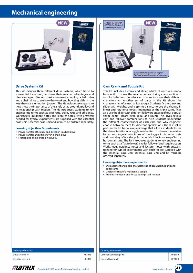
Drive Systems Kit
This kit includes three diff erent drive systems, which fi t on to a essential base unit, to show their relative advantages and disadvantages. Students test a universal coupling, a belt drive and a chain drive to see how they work and how they diff er in the way they transfer motion (power). The kit includes extra parts to help show the importance of the angle of lap around a pulley and its relationship with friction. The kit introduces students to key engineering terms such as gear ratio, pulley ratio and effi ciency. Worksheets, guidance notes and lecturer notes (with answers) needed for typical experiments are supplied with the essential base unit. Essential base unit and kit must be ordered separately.
Learning objectives /experiments
Power transfer, effi ciency and direction in a belt drive Power transfer and effi ciency in a chain drive Friction and angle of lap on a pulley
Ordering information
Drive Systems Kit HP5045
Essential base unit HP5000
Ordering information
Cam crank and Toggle Kit HP5050
Essential base unit HP5000
Cam Crank and Toggle Kit
This kit includes a crank and slider, which fi t onto a essential base unit, to show the relative forces during crank motion. It also includes four popular cam shapes to show their diff erent characteristics. Another set of parts in the kit shows the characteristics of a mechanical toggle. Students fi t the crank and slider with weights and a spring balance to see the change in linear and rotational forces (moments) as the crank turns. They also use the slider with diff erent followers on a set of four popular shape cams - heart, pear, spiral and round. This gives several cam and follower combinations to help students understand the diff erent characteristics of each cam and why engineers choose between them for diff erent applications. The last set of parts in the kit has a simple linkage that allows students to see the characteristics of a toggle mechanism. Its shows the relative forces and angular conditions of the toggle in its initial state and how they aff ect the point at which it locks or ‘snaps’ into a horizontal state. The kit introduces students to key engineering terms such as a ‘fl at follower’, a ‘roller follower’ and ‘toggle action’. Worksheets, guidance notes and lecturer notes (with answers) needed for typical experiments with each kit are supplied with the essential base unit. Essential base unit and kit must be ordered separately.
Learning objectives /experiments
Displacement and angle characteristics of pear, heart, round and spiral cams Characteristics of a mechanical toggle Turning moments and forces during crank motion
Mechanical engineering
Suitable for Unit 2 of BTEC Higher National: Engineering Science
Suitable for unit 60 of BTEC Higher National award: Dynamics of machines
Copyright © 2016 Matrix Technology Solutions Limited www.matrixtsl.com42
Potential and kinetic energy kit
www.matrixtsl.com Copyright © 2015 Matrix Technology Solutions Ltd
Simplifying Technology
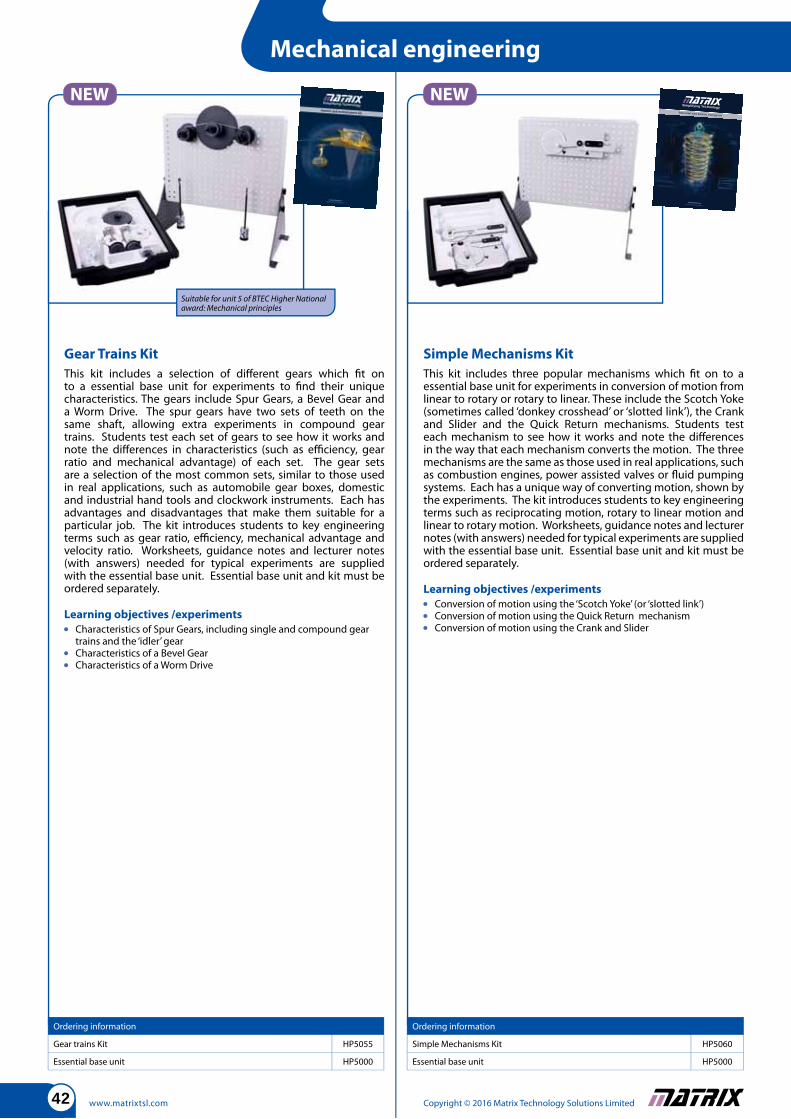
Gear Trains Kit
This kit includes a selection of diff erent gears which fi t on to a essential base unit for experiments to fi nd their unique characteristics. The gears include Spur Gears, a Bevel Gear and a Worm Drive. The spur gears have two sets of teeth on the same shaft, allowing extra experiments in compound gear trains. Students test each set of gears to see how it works and note the diff erences in characteristics (such as effi ciency, gear ratio and mechanical advantage) of each set. The gear sets are a selection of the most common sets, similar to those used in real applications, such as automobile gear boxes, domestic and industrial hand tools and clockwork instruments. Each has advantages and disadvantages that make them suitable for a particular job. The kit introduces students to key engineering terms such as gear ratio, effi ciency, mechanical advantage and velocity ratio. Worksheets, guidance notes and lecturer notes (with answers) needed for typical experiments are supplied with the essential base unit. Essential base unit and kit must be ordered separately.
Learning objectives /experiments
Characteristics of Spur Gears, including single and compound gear trains and the ‘idler’ gear Characteristics of a Bevel Gear Characteristics of a Worm Drive
Ordering information
Gear trains Kit HP5055
Essential base unit HP5000
Ordering information
Simple Mechanisms Kit HP5060
Essential base unit HP5000
Simple Mechanisms Kit
This kit includes three popular mechanisms which fi t on to a essential base unit for experiments in conversion of motion from linear to rotary or rotary to linear. These include the Scotch Yoke (sometimes called ‘donkey crosshead’ or ‘slotted link’), the Crank and Slider and the Quick Return mechanisms. Students test each mechanism to see how it works and note the diff erences in the way that each mechanism converts the motion. The three mechanisms are the same as those used in real applications, such as combustion engines, power assisted valves or fl uid pumping systems. Each has a unique way of converting motion, shown by the experiments. The kit introduces students to key engineering terms such as reciprocating motion, rotary to linear motion and linear to rotary motion. Worksheets, guidance notes and lecturer notes (with answers) needed for typical experiments are supplied with the essential base unit. Essential base unit and kit must be ordered separately.
Learning objectives /experiments
Conversion of motion using the ‘Scotch Yoke’ (or ‘slotted link’) Conversion of motion using the Quick Return mechanism Conversion of motion using the Crank and Slider
Mechanical engineering
Suitable for unit 5 of BTEC Higher National award: Mechanical principles

www.matrixtsl.comCopyright © 2016 Matrix Technology Solutions Limited 43
Linear and rotational dynamics
This kit includes a dynamics track, handheld datalogger with LCD screen, and a range of sensors and accessories that allow students and teachers to carry out a range of experiments in dynamics. The datalogger can be used independently of a PC for many experiments with data automatically passed to Excel for further analysis. The datalogger has a VGA output which makes the equipment perfect for classroom demonstrations. The equipment is supplied with a suite of worksheets and teacher support material.
Learning objectives /experiments
Parameters of Kinetics: displacement, velocity, acceleration Equations of motion Parameters of dynamics: inertia, acceleration, force, momentum,
mechanical work and power Newton’s laws of motion, conservation of momentum and energy Linear and angular motion Rotational dynamics Simple Harmonic motion
Ordering information
Linear and rotational dynamics HP5099
Ordering information QTY
Tetrix prime starter set 1 HP2810
Either: Arduino development centre with printed base plate 1 HP9769
Or: PIC development centre with printed base plate 1 HP4988
E-blocks servo board 1 EB059
E-blocks motor control board 1 EB094
E-blocks screw terminal board 1 EB002
Power supply 1 HP2666
USB lead 1 HPUSB
Microcontrollers for Mechanical engineers
This solution provides a suite of microcontroller hardware as well as a kit of parts from which a number of mechanical models can be constructed using the Tetrix construction kit. The kit can be based on our Development centre for either PICmicro or Arduino microcontrollers supplied with additional servo board, motor control board and screw terminal interface board.
Learning objectives /experiments
Microcontroller programming and circuits, clocks, pins, inputs, outputs, ports, memory and memory types, current limits Programming using fl owcharts, Arduino or MPLAB: input, system,
output, loops, decision, subroutine, go to, calculations, delays, variables, strings, A/D conversion, interrupts, hardware macros, software macros, arrays Techniques: Binary, Hexadecimal, ASCII, calculations Components:
clocking devices, switches, LEDs, LED arrays, sensors, LCD, 7-segment displays, quad 7-segment displays, power supply, EEPROM Techniques: switch de-bounce, Schmitt trigger, prototyping with
E-blocks strip board
Mechanical engineering
Suitable for unit 2 of the BTEC Higher National in Engineering: Engineering Science
Suitable for BTEC National unit 6: Microcontrollers
Suitable for unit 1 of the BTEC National in Engineering: Engineering principles
Suitable for unit 28 of the BTEC National in Engineering: Dynamic mechanical principles and practice
The datalogger included is fully self-contained and has a VGA output for connection to a projector for class demonstrations.
For an explanation of icons please see page 6
Arm made up from Tetrix.
Copyright © 2016 Matrix Technology Solutions Limited www.matrixtsl.com44
Components included
2 Reed switch and holder 2 Switch, push to make
2 Microswitch 1 Valve, 3/2, solenoid-spring
1 Valve, 5/2, solenoid -spring 2 Valve, double solenoid
6 Lead, 4mm plugs, black 6 Lead, 4mm plugs, red
1 Power supply
Ordering information
Electro-pneumatics add-on kit AU9015
You may also need...
Automatics essentials solution AU9020
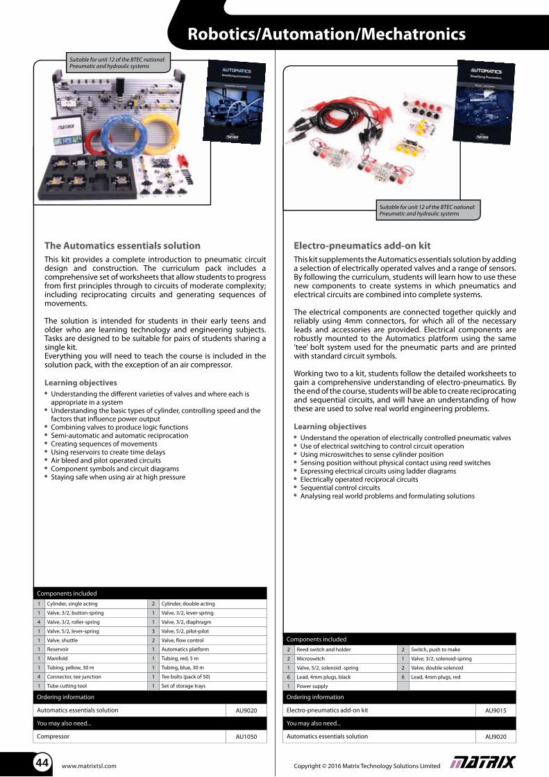
Electro-pneumatics add-on kit
This kit supplements the Automatics essentials solution by adding a selection of electrically operated valves and a range of sensors. By following the curriculum, students will learn how to use these new components to create systems in which pneumatics and electrical circuits are combined into complete systems.
The electrical components are connected together quickly and reliably using 4mm connectors, for which all of the necessary leads and accessories are provided. Electrical components are robustly mounted to the Automatics platform using the same ‘tee’ bolt system used for the pneumatic parts and are printed with standard circuit symbols.
Working two to a kit, students follow the detailed worksheets to gain a comprehensive understanding of electro-pneumatics. By the end of the course, students will be able to create reciprocating and sequential circuits, and will have an understanding of how these are used to solve real world engineering problems.
Learning objectives Understand the operation of electrically controlled pneumatic valves Use of electrical switching to control circuit operation Using microswitches to sense cylinder position Sensing position without physical contact using reed switches Expressing electrical circuits using ladder diagrams Electrically operated reciprocal circuits Sequential control circuits Analysing real world problems and formulating solutions
Suitable for unit 12 of the BTEC national: Pneumatic and hydraulic systems
The Automatics essentials solution
This kit provides a complete introduction to pneumatic circuit design and construction. The curriculum pack includes a comprehensive set of worksheets that allow students to progress from fi rst principles through to circuits of moderate complexity; including reciprocating circuits and generating sequences of movements.
The solution is intended for students in their early teens and older who are learning technology and engineering subjects. Tasks are designed to be suitable for pairs of students sharing a single kit.Everything you will need to teach the course is included in the solution pack, with the exception of an air compressor.
Learning objectives Understanding the diff erent varieties of valves and where each is
appropriate in a system Understanding the basic types of cylinder, controlling speed and the
factors that infl uence power output Combining valves to produce logic functions Semi-automatic and automatic reciprocation Creating sequences of movements Using reservoirs to create time delays Air bleed and pilot operated circuits Component symbols and circuit diagrams Staying safe when using air at high pressure
Components included
1 Cylinder, single acting 2 Cylinder, double acting
1 Valve, 3/2, button-spring 1 Valve, 3/2, lever-spring
4 Valve, 3/2, roller-spring 1 Valve, 3/2, diaphragm
1 Valve, 5/2, lever-spring 3 Valve, 5/2, pilot-pilot
1 Valve, shuttle 2 Valve, fl ow control
1 Reservoir 1 Automatics platform
1 Manifold 1 Tubing, red, 5 m
1 Tubing, yellow, 30 m 1 Tubing, blue, 30 m
4 Connector, tee junction 1 Tee bolts (pack of 50)
1 Tube cutting tool 1 Set of storage trays
Ordering information
Automatics essentials solution AU9020
You may also need...
Compressor AU1050
Suitable for unit 12 of the BTEC national: Pneumatic and hydraulic systems
Robotics/Automation/Mechatronics
www.matrixtsl.comCopyright © 2016 Matrix Technology Solutions Limited 45
Components included
1 MIAC controller 2 Switch, push to make
1 Reed switch and holder 2 Valve, fl ow control
1 Light sensor 4 Valve, 3/2, solenoid-spring
1 Power supply 1 Power distribution carrier
6 Lead, 4mm plugs, red 6 Lead, 4mm plugs, black
2 Lead, 4mm plugs, yellow
Ordering information
Automatics control add-on kit AU9010
You may also need...
Automatics essentials solution AU9020
Flowcode See page 62
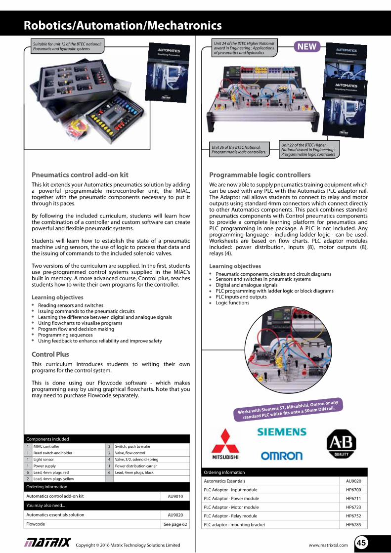
Pneumatics control add-on kit
This kit extends your Automatics pneumatics solution by adding a powerful programmable microcontroller unit, the MIAC, together with the pneumatic components necessary to put it through its paces.
By following the included curriculum, students will learn how the combination of a controller and custom software can create powerful and fl exible pneumatic systems.
Students will learn how to establish the state of a pneumatic machine using sensors, the use of logic to process that data and the issuing of commands to the included solenoid valves.
Two versions of the curriculum are supplied. In the fi rst, students use pre-programmed control systems supplied in the MIAC’s built in memory. A more advanced course, Control plus, teaches students how to write their own programs for the controller.
Learning objectives Reading sensors and switches Issuing commands to the pneumatic circuits Learning the diff erence between digital and analogue signals Using fl owcharts to visualise programs Program fl ow and decision making Programming sequences Using feedback to enhance reliability and improve safety
Control Plus
This curriculum introduces students to writing their own programs for the control system.
This is done using our Flowcode software - which makes programming easy by using graphical fl owcharts. Note that you may need to purchase Flowcode separately.
Suitable for unit 12 of the BTEC national: Pneumatic and hydraulic systems
Programmable logic controllers
We are now able to supply pneumatics training equipment which can be used with any PLC with the Automatics PLC adaptor rail. The Adaptor rail allows students to connect to relay and motor outputs using standard 4mm connectors which connect directly to other Automatics components. This pack combines standard pneumatics components with Control pneumatics components to provide a complete learning platform for pneumatics and PLC programming in one package. A PLC is not included. Any programming language - including ladder logic - can be used. Worksheets are based on fl ow charts. PLC adaptor modules included: power distribution, inputs (8), motor outputs (8), relays (4).
Learning objectives
Pneumatic components, circuits and circuit diagrams Sensors and switches in pneumatic systems Digital and analogue signals PLC programming with ladder logic or block diagrams PLC inputs and outputs Logic functions
Unit 22 of the BTEC Higher National award in Engineering : Prorgammable logic controllers
Unit 24 of the BTEC Higher National award in Engineering : Applications of pneumatics and hydraulics
Ordering information
Automatics Essentials AU9020
PLC Adaptor - Input module HP6700
PLC Adaptor - Power module HP6711
PLC Adaptor - Motor module HP6723
PLC Adaptor - Relay module HP6752
PLC adaptor - mounting bracket HP6785
Unit 36 of the BTEC National: Programmable logic controllers.
Robotics/Automation/Mechatronics
Works with Siemens S7, Mitsubishi, Omron or any
standard PLC which fi ts onto a 50mm DIN rail.
Copyright © 2016 Matrix Technology Solutions Limited www.matrixtsl.com46
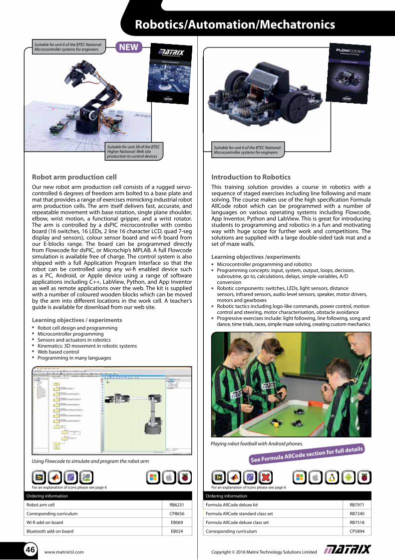
Robot arm production cell
Our new robot arm production cell consists of a rugged servo-controlled 6 degrees of freedom arm bolted to a base plate and mat that provides a range of exercises mimicking industrial robot arm production cells. The arm itself delivers fast, accurate, and repeatable movement with base rotation, single plane shoulder, elbow, wrist motion, a functional gripper, and a wrist rotator. The arm is controlled by a dsPIC microcontroller with combo board (16 switches, 16 LEDs, 2 line 16 character LCD, quad 7-seg display and sensors), colour sensor board and wi-fi board from our E-blocks range. The board can be programmed directly from Flowcode for dsPIC, or Microchip’s MPLAB. A full Flowcode simulation is available free of charge. The control system is also shipped with a full Application Program Interface so that the robot can be controlled using any wi-fi enabled device such as a PC, Android, or Apple device using a range of software applications including C++, LabView, Python, and App Inventor as well as remote applications over the web. The kit is supplied with a number of coloured wooden blocks which can be moved by the arm into diff erent locations in the work cell. A teacher’s guide is available for download from our web site.
Learning objectives / experiments Robot cell design and programming Microcontroller programming Sensors and actuators in robotics Kinematics: 3D movement in robotic systems Web based control Programming in many languages
Ordering information
Robot arm cell RB6231
Corresponding curriculum CP8656
Wi-fi add-on board EB069
Bluetooth add-on board EB024
Suitable for unit 38 of the BTEC Higher National: Web site production to control devices
Suitable for unit 6 of the BTEC National: Microcontroller systems for engineers
Robotics/Automation/Mechatronics
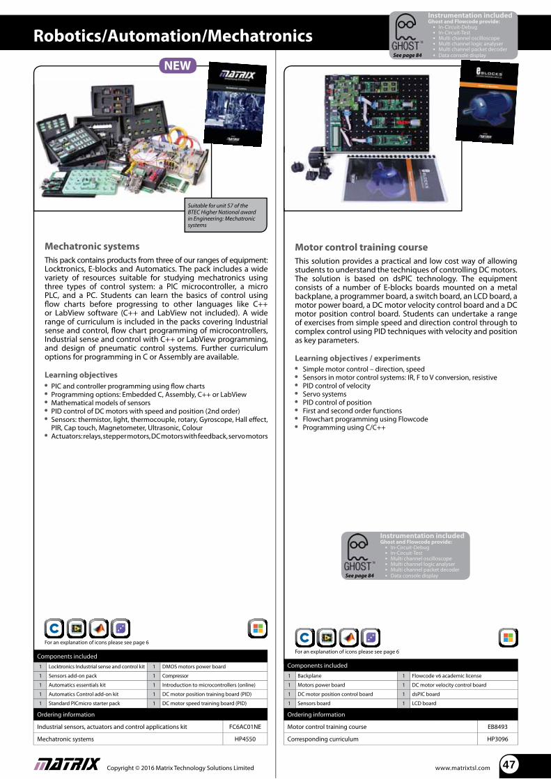
Introduction to Robotics
This training solution provides a course in robotics with a sequence of staged exercises including line following and maze solving. The course makes use of the high specifi cation Formula AllCode robot which can be programmed with a number of languages on various operating systems including Flowcode, App Inventor, Python and LabView. This is great for introducing students to programming and robotics in a fun and motivating way with huge scope for further work and competitions. The solutions are supplied with a large double-sided task mat and a set of maze walls.
Learning objectives /experiments Microcontroller programming and robotics Programming concepts: input, system, output, loops, decision,
subroutine, go to, calculations, delays, simple variables, A/D conversion Robotic components: switches, LEDs, light sensors, distance
sensors, infrared sensors, audio level sensors, speaker, motor drivers, motors and gearboxes Robotic tactics including logo-like commands, power control, motion
control and steering, motor characterisation, obstacle avoidance Progressive exercises include: light following, line following, song and
dance, time trials, races, simple maze solving, creating custom mechanics
Ordering information
Formula AllCode deluxe kit RB7971
Formula AllCode standard class set RB7240
Formula AllCode deluxe class set RB7518
Corresponding curriculum CP5894
Playing robot football with Android phones.
Suitable for unit 6 of the BTEC National: Microcontroller systems for engineers
See Formula AllCode section for full details
Using Flowcode to simulate and program the robot arm
For an explanation of icons please see page 6 For an explanation of icons please see page 6
www.matrixtsl.comCopyright © 2016 Matrix Technology Solutions Limited 47
Motor control training course
This solution provides a practical and low cost way of allowing students to understand the techniques of controlling DC motors. The solution is based on dsPIC technology. The equipment consists of a number of E-blocks boards mounted on a metal backplane, a programmer board, a switch board, an LCD board, a motor power board, a DC motor velocity control board and a DC motor position control board. Students can undertake a range of exercises from simple speed and direction control through to complex control using PID techniques with velocity and position as key parameters.
Learning objectives / experiments Simple motor control – direction, speed Sensors in motor control systems: IR, F to V conversion, resistive PID control of velocity Servo systems PID control of position First and second order functions Flowchart programming using Flowcode Programming using C/C++
Components included
1 Backplane 1 Flowcode v6 academic license
1 Motors power board 1 DC motor velocity control board
1 DC motor position control board 1 dsPIC board
1 Sensors board 1 LCD board
Ordering information
Motor control training course EB8493
Corresponding curriculum HP3096
Mechatronic systems
This pack contains products from three of our ranges of equipment: Locktronics, E-blocks and Automatics. The pack includes a wide variety of resources suitable for studying mechatronics using three types of control system: a PIC microcontroller, a micro PLC, and a PC. Students can learn the basics of control using fl ow charts before progressing to other languages like C++ or LabView software (C++ and LabView not included). A wide range of curriculum is included in the packs covering Industrial sense and control, fl ow chart programming of microcontrollers, Industrial sense and control with C++ or LabView programming, and design of pneumatic control systems. Further curriculum options for programming in C or Assembly are available.
Learning objectives PIC and controller programming using fl ow charts Programming options: Embedded C, Assembly, C++ or LabView Mathematical models of sensors PID control of DC motors with speed and position (2nd order) Sensors: thermistor, light, thermocouple, rotary, Gyroscope, Hall eff ect,
PIR, Cap touch, Magnetometer, Ultrasonic, Colour Actuators: relays, stepper motors, DC motors with feedback, servo motors
Suitable for unit 57 of the BTEC Higher National award in Engineering: Mechatronic systems
Components included
1 Locktronics Industrial sense and control kit 1 DMOS motors power board
1 Sensors add-on pack 1 Compressor
1 Automatics essentials kit 1 Introduction to microcontrollers (online)
1 Automatics Control add-on kit 1 DC motor position training board (PID)
1 Standard PICmicro starter pack 1 DC motor speed training board (PID)
Ordering information
Industrial sensors, actuators and control applications kit FC6AC01NE
Mechatronic systems HP4550
Robotics/Automation/Mechatronics
Instrumentation includedGhost and Flowcode provide: In-Circuit-Debug In-Circuit-Test Multi channel oscilloscope Multi channel logic analyser Multi channel packet decoder Data console displaySee page 84
Instrumentation includedGhost and Flowcode provide: In-Circuit-Debug In-Circuit-Test Multi channel oscilloscope Multi channel logic analyser Multi channel packet decoder Data console displaySee page 84
For an explanation of icons please see page 6
For an explanation of icons please see page 6
Copyright © 2016 Matrix Technology Solutions Limited www.matrixtsl.com48
Robotics/Automation/Mechatronics
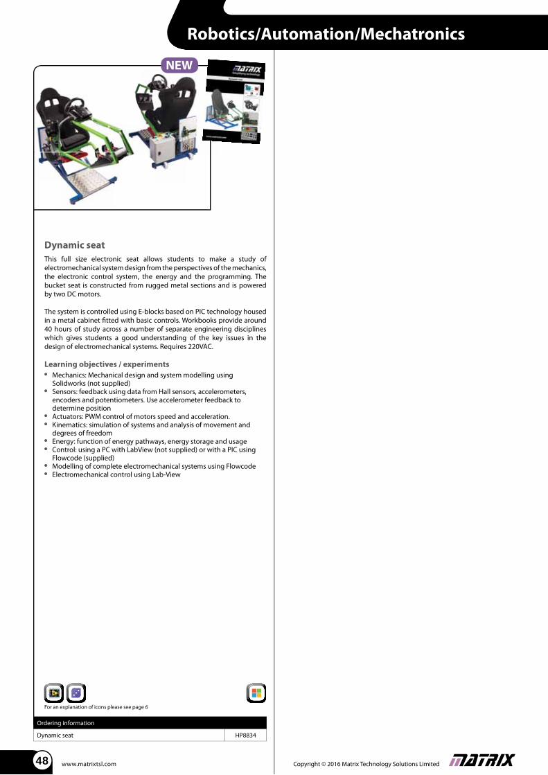
Dynamic seat
This full size electronic seat allows students to make a study of electromechanical system design from the perspectives of the mechanics, the electronic control system, the energy and the programming. The bucket seat is constructed from rugged metal sections and is powered by two DC motors.
The system is controlled using E-blocks based on PIC technology housed in a metal cabinet fi tted with basic controls. Workbooks provide around 40 hours of study across a number of separate engineering disciplines which gives students a good understanding of the key issues in the design of electromechanical systems. Requires 220VAC.
Learning objectives / experiments Mechanics: Mechanical design and system modelling using
Solidworks (not supplied) Sensors: feedback using data from Hall sensors, accelerometers,
encoders and potentiometers. Use accelerometer feedback to determine position Actuators: PWM control of motors speed and acceleration. Kinematics: simulation of systems and analysis of movement and
degrees of freedom Energy: function of energy pathways, energy storage and usage Control: using a PC with LabView (not supplied) or with a PIC using
Flowcode (supplied) Modelling of complete electromechanical systems using Flowcode Electromechanical control using Lab-View
Ordering information
Dynamic seat HP8834
For an explanation of icons please see page 6