Embed Size (px)
Citation preview
Page 93
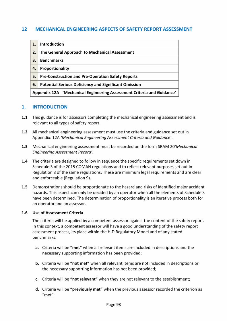
12 MECHANICAL ENGINEERING ASPECTS OF SAFETY REPORT ASSESSMENT
1. Introduction
2. The General Approach to Mechanical Assessment
3. Benchmarks
4. Proportionality
5. Pre-Construction and Pre-Operation Safety Reports
6. Potential Serious Deficiency and Significant Omission
Appendix 12A - ‘Mechanical Engineering Assessment Criteria and Guidance’
1. INTRODUCTION
1.1 This guidance is for assessors completing the mechanical engineering assessment and is relevant to all types of safety report.
1.2 All mechanical engineering assessment must use the criteria and guidance set out in Appendix: 12A ‘Mechanical Engineering Assessment Criteria and Guidance’.
1.3 Mechanical engineering assessment must be recorded on the form SRAM 20‘Mechanical Engineering Assessment Record’.
1.4 The criteria are designed to follow in sequence the specific requirements set down in Schedule 3 of the 2015 COMAH regulations and to reflect relevant purposes set out in Regulation 8 of the same regulations. These are minimum legal requirements and are clear and enforceable (Regulation 9).
1.5 Demonstrations should be proportionate to the hazard and risks of identified major accident hazards. This aspect can only be decided by an operator when all the elements of Schedule 3 have been determined. The determination of proportionality is an iterative process both for an operator and an assessor.
1.6 Use of Assessment Criteria
The criteria will be applied by a competent assessor against the content of the safety report. In this context, a competent assessor will have a good understanding of the safety report assessment process, its place within the HID Regulatory Model and of any stated benchmarks.
a. Criteria will be “met” when all relevant items are included in descriptions and the necessary supporting information has been provided;
b. Criteria will be “not met” when all relevant items are not included in descriptions or the necessary supporting information has not been provided;
c. Criteria will be “not relevant” when they are not relevant to the establishment;
d. Criteria will be “previously met” when the previous assessor recorded the criterion as “met”.
Page 94
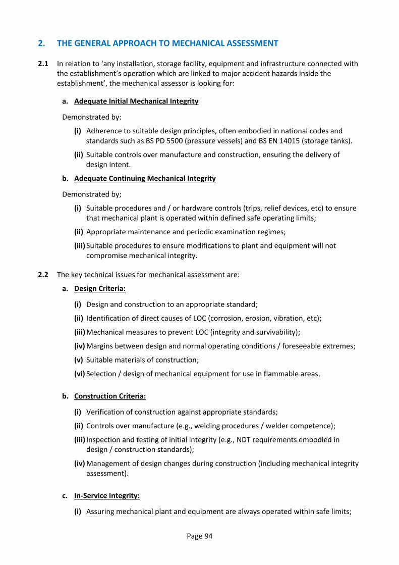
2. THE GENERAL APPROACH TO MECHANICAL ASSESSMENT
2.1 In relation to ‘any installation, storage facility, equipment and infrastructure connected with the establishment’s operation which are linked to major accident hazards inside the establishment’, the mechanical assessor is looking for:
a. Adequate Initial Mechanical Integrity
Demonstrated by:
(i) Adherence to suitable design principles, often embodied in national codes and standards such as BS PD 5500 (pressure vessels) and BS EN 14015 (storage tanks).
(ii) Suitable controls over manufacture and construction, ensuring the delivery of design intent.
b. Adequate Continuing Mechanical Integrity
Demonstrated by;
(i) Suitable procedures and / or hardware controls (trips, relief devices, etc) to ensure that mechanical plant is operated within defined safe operating limits;
(ii) Appropriate maintenance and periodic examination regimes;
(iii) Suitable procedures to ensure modifications to plant and equipment will not compromise mechanical integrity.
2.2 The key technical issues for mechanical assessment are:
a. Design Criteria:
(i) Design and construction to an appropriate standard;
(ii) Identification of direct causes of LOC (corrosion, erosion, vibration, etc);
(iii) Mechanical measures to prevent LOC (integrity and survivability);
(iv) Margins between design and normal operating conditions / foreseeable extremes;
(v) Suitable materials of construction;
(vi) Selection / design of mechanical equipment for use in flammable areas.
b. Construction Criteria:
(i) Verification of construction against appropriate standards;
(ii) Controls over manufacture (e.g., welding procedures / welder competence);
(iii) Inspection and testing of initial integrity (e.g., NDT requirements embodied in design / construction standards);
(iv) Management of design changes during construction (including mechanical integrity assessment).
c. In-Service Integrity:
(i) Assuring mechanical plant and equipment are always operated within safe limits;
Page 95
(ii) Management of change (ensuring mechanical integrity is not compromised by equipment, process or operating and maintenance system changes).
d. Maintenance / Inspection Criteria
(i) Prioritisation of safety critical equipment;
(ii) Appropriate maintenance / inspection regimes and philosophies (including procedures for periodic review);
(iii) Identified degradation mechanisms reflected in Written Schemes of Examination;
(iv) Competence of maintenance / inspection personnel;
(v) Analysis of maintenance / inspection findings (by a competent person);
(vi) Performance monitoring of integrity assurance systems. e. Ageing Plant
‘‘Ageing’ is not directly related to chronological age’ [2], but to damage or material deterioration of plant or equipment. Ageing mechanisms (such as erosion, corrosion, fatigue, etc) lead to an increased risk of loss of containment.
The safety report should describe (where applicable):
(i) The specified design basis for major equipment items and how the impact of the selected design (e.g., pressure / temperature rating, material, corrosion allowance, etc) on in-service operating parameters, inspection, testing and maintenance requirements is assessed;
(ii) Procedures for identifying ageing and determining the condition of mechanical plant and equipment (e.g., from comprehensive inspection / maintenance history, measured corrosion rates, operational performance, etc);
(iii) Assessment procedures / justification required prior to operating plant beyond its specified design life (rather than repairing / replacing the plant). Requirements for increased inspection (to inform the assessment or to monitor ongoing condition of plant) should also be described, where appropriate;
(iv) Reviews / gap analysis completed to compare the design of older plant (potentially affording lower integrity) with relevant up-to-date design principles and the consideration of further measures (such as de-rating equipment, reducing fill levels on storage tanks, etc) to reduce risk to ALARP where appropriate;
(v) Any requirement for fitness-for-service / remnant life assessment techniques (such as API 579, BS 7910) to be employed, to enable major equipment items to be returned to service following inspection. Assessor competency requirements should also be described.
3. BENCHMARKS
3.1 The benchmarks employed by the mechanical assessor (to determine whether assessment criteria have been met) will depend upon the nature and complexity of the establishment described within the safety report and the mechanical plant and equipment installed.
Page 96
3.2 The mechanical engineering assessment criteria guidance identifies some commonly adopted national standards, with further benchmarks provided within HSE equipment / topic specific guidance (as referenced in SRAM Appendix 12A: ‘Mechanical criteria and guidance’).
4. PROPORTIONALITY
4.1 The depth of the analysis in the operator's risk assessment should be proportionate to the hazards and risks presented by the establishment. Further guidance on proportionality is included in the SRAM.
4.2 The nature and extent of the demonstration required of the operator will be guided by the hazards involved with the establishment’s operation and the potential consequences of the major accident scenarios described in the safety report. For example, evidence of a full risk-based inspection (RBI) regime may be required within a refinery safety report but is unlikely to be appropriate for a simple chemical warehouse.
5. PRE-CONSTRUCTION AND PRE-OPERATION SAFETY REPORTS
5.1 Mechanical engineering assessment of Pre-Construction reports is concerned primarily with:
(i) The conceptual design of a new installation (including demonstration that inherent safety principles were adopted within the design selection processes);
(ii) Identification of potential major accident hazards and associated technical measures to prevent loss of containment;
(iii) Front End Engineering Design (FEED), identifying the technical requirements for the project (specifications for major equipment items, design code requirements, etc).
5.2 Pre-Operation safety reports should include details of significant changes to the previously specified design and relevant additional information resulting from the detailed engineering phase. Procedures for managing the hazards associated with plant commissioning procedures should also be described.
5.3 For large projects (involving external design / construction contractors) the operator’s arrangements for managing outstanding issues / actions (‘snag items’) identified during ‘pre-handover’ inspection should be described. Residual issues classified as ‘low-risk’ at the project handover stage (e.g., incomplete painting of pipework systems) may impact in-service integrity, if timely remedial action is not taken.
5.4 The timing of submission of Pre-Construction and Pre-Operation reports limits the information available for CA assessment. In some industry sectors, new installations may be constructed and brought into operation in various phases over a number of years (for example, underground gas storage installations). In this instance, the use of a rolling submission programme (for both pre-construction and pre-operation safety reports) may be appropriate.
6 POTENTIAL SERIOUS DEFICIENCY AND SIGNIFICANT OMISSION
6.1 Examples of potential serious deficiencies in the on-site measures (as described in the safety report) include but are not limited to:
Page 97
(i) The absence of a proactive maintenance and inspection regime to ensure the integrity of critical mechanical plant and equipment on site which contains hazardous substances. [Criteria 12.2.4.1, 12.2.4.3]
(ii) No system in place to ensure compliance with the requirements of the Pressure Systems Safety Regulations (PSSR) 2000. [Criterion 12.2.4.3]
(iii) The absence of procedures for assessing the mechanical integrity of proposed modifications to critical plant and equipment. [Criterion 12.2.5.1]
6.2 Significant omissions in the content of the safety report may include:
(i) No description or a lack of detail on the design basis / design standards adopted for mechanical plant and equipment forming the primary containment boundary. [Criterion 12.2.1.1]
(ii) No explanation of how the identification of potential direct causes of loss of containment (such as corrosion, erosion, etc) has been conducted. [Criterion 12.2.1.6]
Appendix 12A - ‘Mechanical Engineering Assessment Criteria and Guidance’
Page 98
TECHNICAL CRITERION GUIDANCE
Link with Predictive Criteria
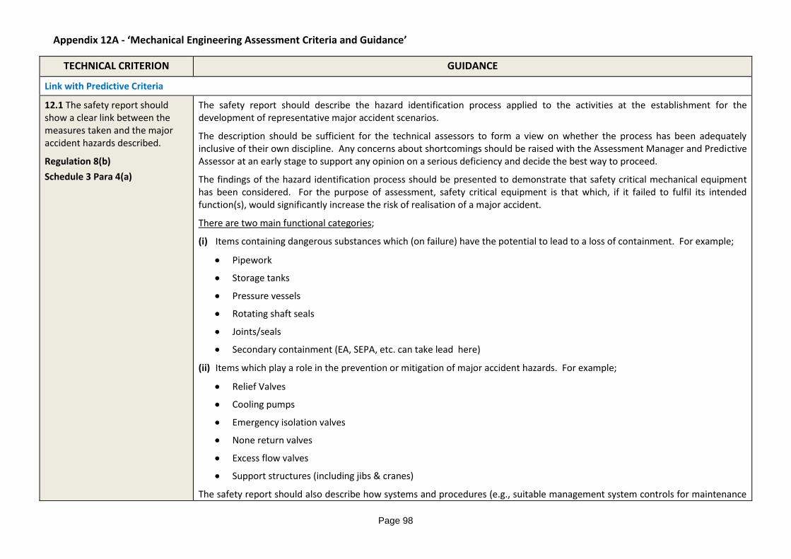
12.1 The safety report should show a clear link between the measures taken and the major accident hazards described.
Regulation 8(b)
Schedule 3 Para 4(a)
The safety report should describe the hazard identification process applied to the activities at the establishment for the development of representative major accident scenarios.
The description should be sufficient for the technical assessors to form a view on whether the process has been adequately inclusive of their own discipline. Any concerns about shortcomings should be raised with the Assessment Manager and Predictive Assessor at an early stage to support any opinion on a serious deficiency and decide the best way to proceed.
The findings of the hazard identification process should be presented to demonstrate that safety critical mechanical equipment has been considered. For the purpose of assessment, safety critical equipment is that which, if it failed to fulfil its intended function(s), would significantly increase the risk of realisation of a major accident.
There are two main functional categories;
(i) Items containing dangerous substances which (on failure) have the potential to lead to a loss of containment. For example;
Pipework
Storage tanks
Pressure vessels
Rotating shaft seals
Joints/seals
Secondary containment (EA, SEPA, etc. can take lead here)
(ii) Items which play a role in the prevention or mitigation of major accident hazards. For example;
Relief Valves
Cooling pumps
Emergency isolation valves
None return valves
Excess flow valves
Support structures (including jibs & cranes)
The safety report should also describe how systems and procedures (e.g., suitable management system controls for maintenance
Appendix 12A - ‘Mechanical Engineering Assessment Criteria and Guidance’
Page 99
TECHNICAL CRITERION GUIDANCE
and inspection schemes) play a role in the prevention of major accident hazards.
To satisfy this criterion the safety report should show a clear link between identification and analysis of hazards with the selection of measures. A suitable hierarchical approach (eliminate, prevent, control, mitigate) to the selection of measures should also be demonstrated. Suitability of the selected measures is assessed in the sub criteria below.
General Principles
12.2 The safety report should show how the measures taken will prevent foreseeable failures which could lead to major accidents.
Schedule 3 Paras 4 and 5
Effectively a summary of all the other criteria, the assessor should come back to this when the other criteria have been assessed, and then conclude:
Whether all the assessed criteria have been met.
How significant the failure to meet one or more criteria is to the overall safety justification.
The recommended actions for improving the safety report and suggested timescales.
The recommendations for follow-up inspection / verification, their priority and timescale.
Design
12.2.1.1 The safety report should describe how the establishment and installations have been designed to an appropriate standard.
Regulation 8(c) Schedule 3 para 5 (d)
This criterion applies to all structures important to safety (e.g., pipe bridges, etc), major vessels, pipework, rotating machines (e.g. pumps, compressors, etc.) and valves if they feature in major accident scenarios.
The Safety Report may describe adequate initial integrity of such items by:
Reference to international design codes and standards (including justification of any deviations / exceptions adopted);
Reference to principal design parameters (design pressure / temperature) and category of construction, if applicable;
Where in-house design codes and standards have been adopted, the Safety Report should demonstrate;
Their relevance; and
How the company has validated them.
Where no standards have been used, the Safety Report should;
Demonstrate how fitness for purpose of such plant / equipment is assured.
Include a description of design reviews conducted (e.g., where novel designs are employed).
Content provided in the Safety Report to assist the demonstration could include:
Appendix 12A - ‘Mechanical Engineering Assessment Criteria and Guidance’
Page 100
TECHNICAL CRITERION GUIDANCE
A table / list detailing the design codes, principal design parameters and category of construction for the major equipment items featuring in the representative MAH scenarios selected.
For less complex establishments (for example, whisky distilleries or chemical warehouses), assessors may expect to see reference to the following standards, codes and guidance (amongst others):
Storage Equipment Manufacturers’ Association (SEMA) Code of Practice on design and installation of racking systems.
United Nations Carriage of Dangerous Goods Regulations (UN approved chemical package designs).
BS EN 12845 on the design, installation and maintenance of fixed (automatic sprinkler) fire-fighting systems.
For highly complex establishments (for example refineries or large-scale chemical / gas processing plants), assessors may expect to see reference to the following standards, codes and guidance (amongst others):
BS EN 13445, PD 5500, ASME VIII, TEMA, etc. (Pressure Vessels).
BS EN 13121, BS EN 13923, etc (GRP / Plastic Vessels and Tanks)
BS EN 14015, API 620, API 650, BS EN 12285, BS EN 12573, etc. (Atmospheric Storage Tanks).
ASME B31.3, LPGA CoP 22, etc. (Pipework).
PD 6550-4, BS EN ISO 13706, BS EN ISO 16812, etc. (Heat exchangers).
BS EN ISO 14847, BS EN ISO 13710, API 674, BS EN ISO 9905, API 610, etc. (Pumps).
BS EN ISO 13631, API 617/618, etc. (Compressors).
Common historic codes (which may have been employed on existing establishments) include:
BS 1500, BS1515, BS 5500 (Pressure Vessels)
BS 2654, BS 4994 (Tanks and Vessels)
Additional relevant references may be found within the COMAH Technical Measures Documents (Design Codes), http://www.hse.gov.uk/comah/sragtech/techmeasindex.htm
In assessing the demonstration that the mechanical design has been considered and the risk reduced to ALARP, assessors should consider the applicability of standards, codes and guidance in each case, and adopt an approach proportionate to the overall risk.
Appendix 12A - ‘Mechanical Engineering Assessment Criteria and Guidance’
Page 101
This criterion is particularly relevant to pre-construction and modification safety reports where good layout (in the design phase) can significantly reduce risk.
TECHNICAL CRITERION GUIDANCE
12.2.1.3 Layout of the plant should limit the risk during operations, inspection, testing, maintenance, modification, repair and replacement.
Regulation 8(c) Schedule 3 Paras 3(d) and 4(a)
The Safety Report should describe how:
Plant layout is considered during the design phase of new builds and for modifications to existing plant;
The layout of the plant will prevent major accidents or limit their effects;
To assist demonstration, the Safety Report should discuss how the following were considered (where applicable) during design of the plant layout:
Plant separation / orientation (e.g. what equipment might fail catastrophically, would it create missiles and where might they go?)
Access requirements (for periodic maintenance / inspection)
Lifting provision (requirements to facilitate the removal of equipment for periodic maintenance / replacement)
Construction / maintenance activities (to minimise the risks from dropped objects, eliminating the need to lift over live plant etc.)
For less complex establishments (for example, whisky distilleries or chemical warehouses), assessors may expect to see reference to the following guidance (amongst others):
SWA Fire Management Guidance
HSE guidance documents HS(G)71, HS(G)140, etc.
For highly complex establishments (for example refineries or large-scale chemical / gas processing plants), assessors may expect to see reference to the following standards, codes and guidance (amongst others):
Institute of Petroleum Model Code of Safe Practice Part 19, HSE guidance document HS(G)176, etc (Tankage layout)
HSE guidance documents HS(G)28, HS(G)40 (Chlorine)
LPGA CoP1
API RP 752 (Location of process plant buildings)
Additional relevant references may be found within the COMAH Technical Measures Documents (Plant Layout).
Appendix 12A - ‘Mechanical Engineering Assessment Criteria and Guidance’
Page 102
TECHNICAL CRITERION GUIDANCE
12.2.1.4 Utilities that are needed to implement any measure defined in the safety report should have suitable reliability, availability and survivability.
Regulation 8(c)
Schedule 3 Paras 4(a) and 5(d)
The Safety Report should describe:
The potential effects of utility failure (in relation to major accident hazards).
The likely impact of utility failure on safety critical mechanical equipment (e.g., primary containment systems).
The measures taken to ensure safety critical utilities will be available when required.
Content provided in the Safety Report to assist demonstration could include:
The design standards for equipment incorporated within safety critical utility supplies.
Details of the monitoring, testing, maintenance and inspection regimes employed for equipment incorporated within safety critical utilities (including backup systems).
Utility failure (mechanical aspects) included in HAZOP’s, PHA’s, PHR’s, etc.
For less complex establishments s (for example, whisky distilleries or chemical warehouses), assessors may expect to see reference to the following standards and guidance (amongst others):
BS 5908, BS EN 13565, BS EN 12845 (Fire fighting systems)
For highly complex establishments (for example refineries or large-scale chemical / gas processing plants), assessors may expect to see reference to the following standards, codes and guidance (amongst others):
ASME Boiler and Pressure Vessel Code, PD5500, etc.
ASME B31.1 (Piping)
SAFed / CEA Guidance for Safe Operation of Boilers (BG01), BS EN 12952 / 3, etc.
API RP 573 Inspection of Fired Boilers and Heaters, etc.
BS EN 1012-1:2010 Compressors and vacuum pumps. Safety requirements. Air compressors, etc.
HS(G)39 (Compressed air safety), etc.
Additional relevant references may be found within the COMAH Technical Measures Documents (Reliability of Utilities)
12.2.1.5 The safety report should show that appropriate measures have been taken to prevent and effectively contain releases of
The Safety Report should describe:
The mechanical measures in place to prevent and / or to contain releases.
The integrity (function, reliability) of such measures and their survivability (i.e., in the event of a fire / major accident).
Appendix 12A - ‘Mechanical Engineering Assessment Criteria and Guidance’
Page 103
TECHNICAL CRITERION GUIDANCE
dangerous substances.
Regulation 8(b and c)
Schedule 3 Para 4(a) and 6(a)
Content provided in the Safety Report to assist demonstration could include discussion of:
The integrity and survivability (where applicable) of mechanical measures such as:
ESDV’s (including fire-safe valve seating arrangements and discussion on Performance Standards, where applicable);
Manually operated isolations in safety critical duty;
Excess flow valves and non-return valves;
Rotating equipment (e.g., protection from reverse rotation / overspeed, cavitation, dry running, deadhead conditions, seal failure, etc.);
Joints (suitability for intended duty of flanged / screwed joints, couplings, etc.);
Temporary repairs (e.g. clamps, wraps);
Dry break couplings;
Bellows and flexible joints;
Secondary containment;
For less complex establishments (for example, chemical warehouses), assessors may expect to see reference to the following guidance (amongst others):
HSE guidance documents HS(G) 51, HS(G)71;
ADR / CDG Regs.
For highly complex establishments (for example refineries or large-scale chemical / gas processing plants), assessors may expect to see reference to the following standards, codes and guidance (amongst others):
HSE guidance documents HS(G) 28, 40, 143, 176, 235, 244, etc.;
Plant design codes (See criterion 12.2.1.1 above);
ASME B31, ASME A182/182M, BS EN 13480, etc (Piping and fittings);
British / EN Standards 4126, 12516, 12567, 1349, 1873, 15714, API Standards / RP’s 526, 594, 602, 609, etc (Valves and actuators);
BS EN Standards 10497 & 60534, API 527, 574, 576 & 598, ANSI FCI 70-2, etc (Valve testing / inspection);
Appendix 12A - ‘Mechanical Engineering Assessment Criteria and Guidance’
Page 104
TECHNICAL CRITERION GUIDANCE
BS EN ISO 21049, BS EN 12756, API Std 682, ATEX (Pump / shaft sealing systems);
API Std 616, RP 688, etc (Equipment protection);
HSE Safety Notice 4/2005 (Weldless pipework repair), ASME B31.3, HSE Note: ‘ Leak sealing repair clamps’, BS EN ISO 24817 (Composite pipework repairs),etc.;
British / EN Standards 6129-1, 14917 (Bellows).
Additional relevant references may be found within the COMAH Technical Measures Documents (Emergency isolation, Emergency response / spill control, Explosion relief, Relief systems / vent systems, Secondary containment, etc).
12.2.1.6 The safety report should show that all foreseeable direct causes of major accidents have been taken into account in the design of the installation.
Regulation 8(b and c)
Schedule 3 Para 5(a)
The Safety Report should describe how:
The following direct causes of loss of containment (where applicable) have been considered in the design of the installation and the selection of mechanical measures:
Corrosion (internal or external)
Variations in process conditions have been considered - the equipment design and materials of construction should accommodate foreseeable changes to the process conditions, such as variations in temperature, corrosive species (for example, during cleaning).
Consideration of inspection requirements during design (e.g., to facilitate the detection and monitoring of corrosion under insulation).
The potential for corrosion has been eliminated or reduced (for example, dead legs have been removed, buried lines minimised etc.).
Corrosion is prevented or controlled by other means, such as cathodic protection and/or the use of coating systems.
Corrosion is managed in other ways, such as employing corrosion allowances.
Erosion:
Consideration should be given to the effect of solids, abrasion, phase changes and cavitation.
External loading:
Consideration as to the suitability of plant, equipment and structures to survive anticipated loadings from external sources, such as wind, rain and snow, as well as process and dynamic loadings. The construction phase should also be considered in addition to normal operation.
Impact:
Appendix 12A - ‘Mechanical Engineering Assessment Criteria and Guidance’
Page 105
TECHNICAL CRITERION GUIDANCE
During operation (e.g., road tanker / fork lift truck impact)
During construction and maintenance activities (e.g., from swinging loads, dropped objects).
From blast loadings etc., (e.g., due to catastrophic failure of adjacent equipment).
Pressure:
The installations are protected from the effects of excessive pressure and/or vacuum, and designed to recognised standards.
Pressure fluctuations are recognised as inducing fatigue failures.
Temperature:
High temperatures are accommodated in the design (e.g., creep resistance) and/or protection systems are in place to prevent damage from excessive temperature.
Low temperature effects are avoided or controlled (e.g., brittle failure, freezing effects).
Changes in temperature are controlled (e.g., thermal fatigue)
Vibration:
Consideration of both machine induced and process induced vibration (high and low frequency, as well as water hammer etc.).
Show elimination (by design), prevention or control of vibration where possible.
Vibration induced fatigue is recognised (e.g., provision of suitable supports for small-bore connections).
Wrong Equipment:
Controls exist for the specification and supply of safety critical equipment and spares.
Management policies to minimise LOC (e.g. avoiding the use of small bore fittings, where possible).
Defective equipment:
Identification / monitoring of pre-existing (design / construction) flaws in areas of high stress, etc.
For less complex establishments (for example, chemical warehouses), assessors may expect to see reference to the following guidance (amongst others):
Appendix 12A - ‘Mechanical Engineering Assessment Criteria and Guidance’
Page 106
It is unacceptable for the safety report to have no explanation of how the identification of direct causes of LOC has been conducted.
TECHNICAL CRITERION GUIDANCE
SEMA Codes of Practice (Racking systems);
HSE guidance documents HS(G) 71, 76;
BS 1449-1.1, etc (Steel plate, sheet and strip);
For highly complex establishments (for example refineries or large-scale chemical / gas processing plants), assessors may expect to see reference to the following standards, codes and guidance (amongst others):
API RP 571 (Damage mechanisms);
L22 (PUWER ACOP);
PER / PSSR;
Plant design codes (See criterion 12.2.1.1 above);
EI Guidelines for the Management of Coatings for External Corrosion Protection;
EI Guidance for corrosion management in oil and gas production and processing;
API RP 520/521, API Std 2000, BS EN ISO 4126-6 (Pressure relief);
BS EN 14620, EEMUA 147 (Refrigerated liquefied gas storage tanks);
IP Guidelines for the Management, Design, Installation and Maintenance of Small Bore Tubing Systems;
MTD Guidelines for the Avoidance of Vibration Induced Fatigue in Process Pipework;
HSE Offshore Technology Report 2002/028: Transient vibration guidelines for fast acting valves screening assessment;
Historic guidance which may have been employed on existing establishments includes (amongst others):
HS(G) 93 (The Assessment of Pressure Vessels Operating at Low Temperature).
API RP 920 (Prevention of Brittle Fracture of Pressure Vessels)
Additional relevant references may be found within the COMAH Technical Measures Documents (Design codes, Corrosion / selection of materials, Relief systems / vent systems, Lifting procedures, Roadways, etc).
Appendix 12A - ‘Mechanical Engineering Assessment Criteria and Guidance’
Page 107
TECHNICAL CRITERION GUIDANCE
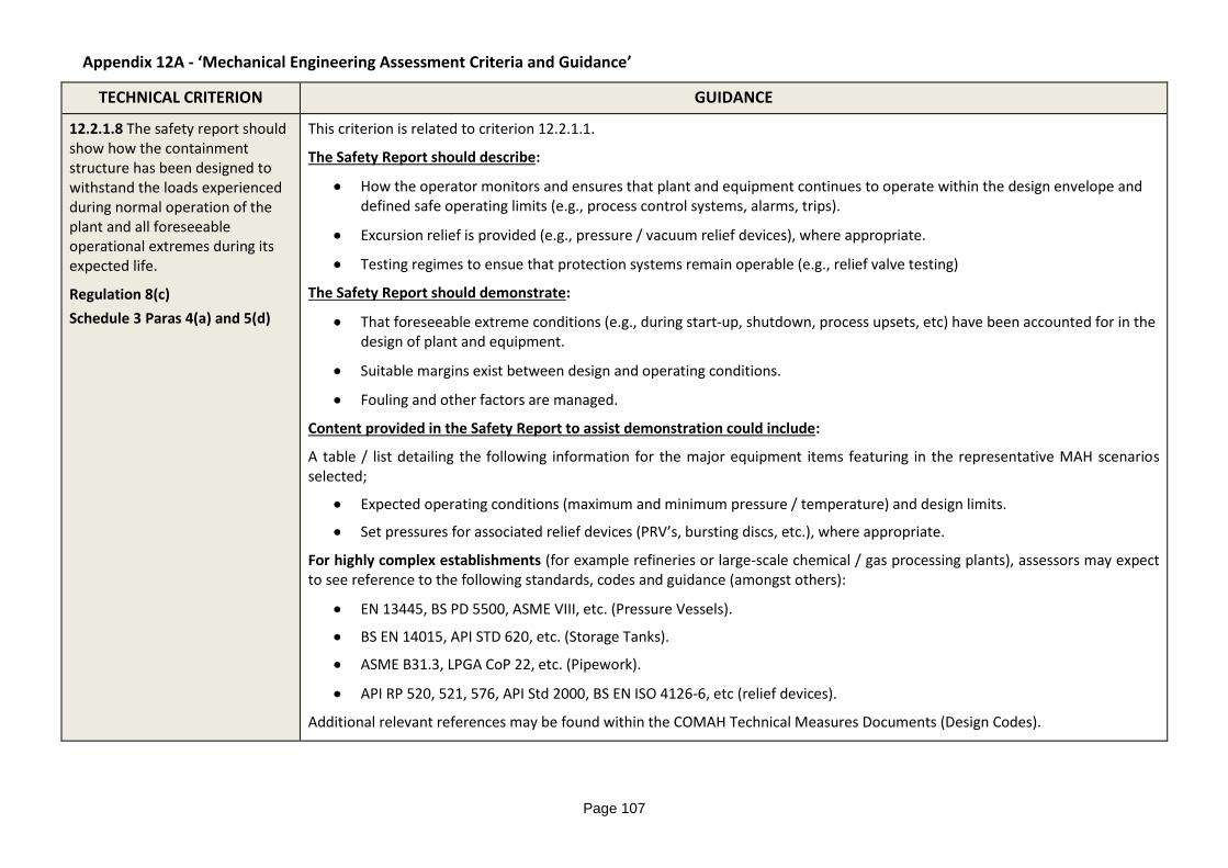
12.2.1.8 The safety report should show how the containment structure has been designed to withstand the loads experienced during normal operation of the plant and all foreseeable operational extremes during its expected life.
Regulation 8(c)
Schedule 3 Paras 4(a) and 5(d)
This criterion is related to criterion 12.2.1.1.
The Safety Report should describe:
How the operator monitors and ensures that plant and equipment continues to operate within the design envelope and defined safe operating limits (e.g., process control systems, alarms, trips).
Excursion relief is provided (e.g., pressure / vacuum relief devices), where appropriate.
Testing regimes to ensue that protection systems remain operable (e.g., relief valve testing)
The Safety Report should demonstrate:
That foreseeable extreme conditions (e.g., during start-up, shutdown, process upsets, etc) have been accounted for in the design of plant and equipment.
Suitable margins exist between design and operating conditions.
Fouling and other factors are managed.
Content provided in the Safety Report to assist demonstration could include:
A table / list detailing the following information for the major equipment items featuring in the representative MAH scenarios selected;
Expected operating conditions (maximum and minimum pressure / temperature) and design limits.
Set pressures for associated relief devices (PRV’s, bursting discs, etc.), where appropriate.
For highly complex establishments (for example refineries or large-scale chemical / gas processing plants), assessors may expect to see reference to the following standards, codes and guidance (amongst others):
EN 13445, BS PD 5500, ASME VIII, etc. (Pressure Vessels).
BS EN 14015, API STD 620, etc. (Storage Tanks).
ASME B31.3, LPGA CoP 22, etc. (Pipework).
API RP 520, 521, 576, API Std 2000, BS EN ISO 4126-6, etc (relief devices).
Additional relevant references may be found within the COMAH Technical Measures Documents (Design Codes).
Appendix 12A - ‘Mechanical Engineering Assessment Criteria and Guidance’
Page 108
TECHNICAL CRITERION GUIDANCE
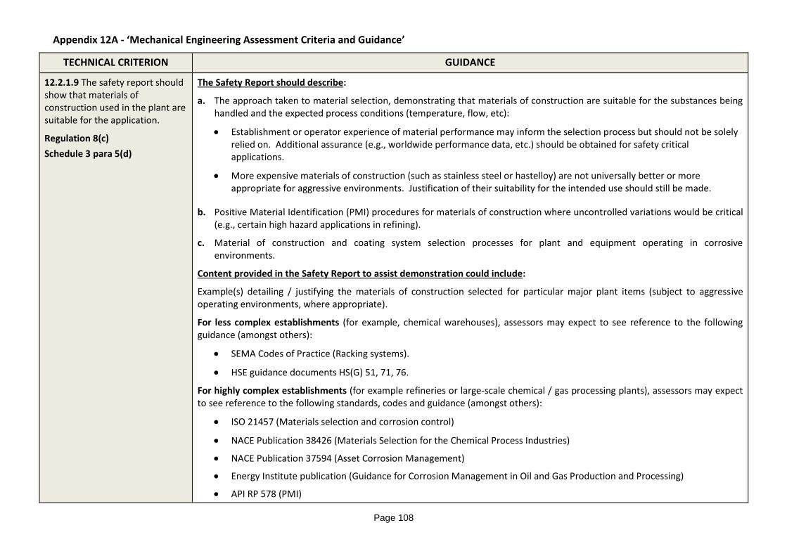
12.2.1.9 The safety report should show that materials of construction used in the plant are suitable for the application.
Regulation 8(c)
Schedule 3 para 5(d)
The Safety Report should describe:
a. The approach taken to material selection, demonstrating that materials of construction are suitable for the substances being handled and the expected process conditions (temperature, flow, etc):
Establishment or operator experience of material performance may inform the selection process but should not be solely relied on. Additional assurance (e.g., worldwide performance data, etc.) should be obtained for safety critical applications.
More expensive materials of construction (such as stainless steel or hastelloy) are not universally better or more appropriate for aggressive environments. Justification of their suitability for the intended use should still be made.
b. Positive Material Identification (PMI) procedures for materials of construction where uncontrolled variations would be critical (e.g., certain high hazard applications in refining).
c. Material of construction and coating system selection processes for plant and equipment operating in corrosive environments.
Content provided in the Safety Report to assist demonstration could include:
Example(s) detailing / justifying the materials of construction selected for particular major plant items (subject to aggressive operating environments, where appropriate).
For less complex establishments (for example, chemical warehouses), assessors may expect to see reference to the following guidance (amongst others):
SEMA Codes of Practice (Racking systems).
HSE guidance documents HS(G) 51, 71, 76.
For highly complex establishments (for example refineries or large-scale chemical / gas processing plants), assessors may expect to see reference to the following standards, codes and guidance (amongst others):
ISO 21457 (Materials selection and corrosion control)
NACE Publication 38426 (Materials Selection for the Chemical Process Industries)
NACE Publication 37594 (Asset Corrosion Management)
Energy Institute publication (Guidance for Corrosion Management in Oil and Gas Production and Processing)
API RP 578 (PMI)
Appendix 12A - ‘Mechanical Engineering Assessment Criteria and Guidance’
Page 109
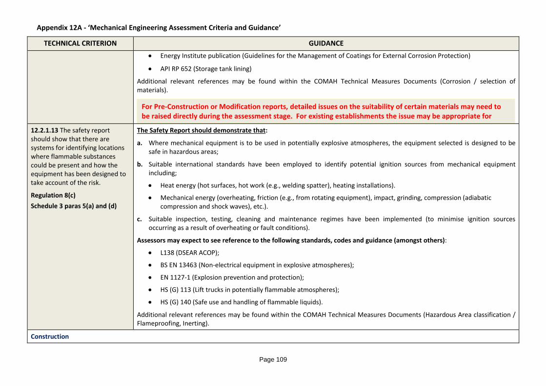
For Pre-Construction or Modification reports, detailed issues on the suitability of certain materials may need to be raised directly during the assessment stage. For existing establishments the issue may be appropriate for inspection.
TECHNICAL CRITERION GUIDANCE
Energy Institute publication (Guidelines for the Management of Coatings for External Corrosion Protection)
API RP 652 (Storage tank lining)
Additional relevant references may be found within the COMAH Technical Measures Documents (Corrosion / selection of materials).
12.2.1.13 The safety report should show that there are systems for identifying locations where flammable substances could be present and how the equipment has been designed to take account of the risk.
Regulation 8(c)
Schedule 3 paras 5(a) and (d)
The Safety Report should demonstrate that:
a. Where mechanical equipment is to be used in potentially explosive atmospheres, the equipment selected is designed to be safe in hazardous areas;
b. Suitable international standards have been employed to identify potential ignition sources from mechanical equipment including;
Heat energy (hot surfaces, hot work (e.g., welding spatter), heating installations).
Mechanical energy (overheating, friction (e.g., from rotating equipment), impact, grinding, compression (adiabatic compression and shock waves), etc.).
c. Suitable inspection, testing, cleaning and maintenance regimes have been implemented (to minimise ignition sources occurring as a result of overheating or fault conditions).
Assessors may expect to see reference to the following standards, codes and guidance (amongst others):
L138 (DSEAR ACOP);
BS EN 13463 (Non-electrical equipment in explosive atmospheres);
EN 1127-1 (Explosion prevention and protection);
HS (G) 113 (Lift trucks in potentially flammable atmospheres);
HS (G) 140 (Safe use and handling of flammable liquids).
Additional relevant references may be found within the COMAH Technical Measures Documents (Hazardous Area classification / Flameproofing, Inerting).
Construction
Appendix 12A - ‘Mechanical Engineering Assessment Criteria and Guidance’
Page 110
TECHNICAL CRITERION GUIDANCE
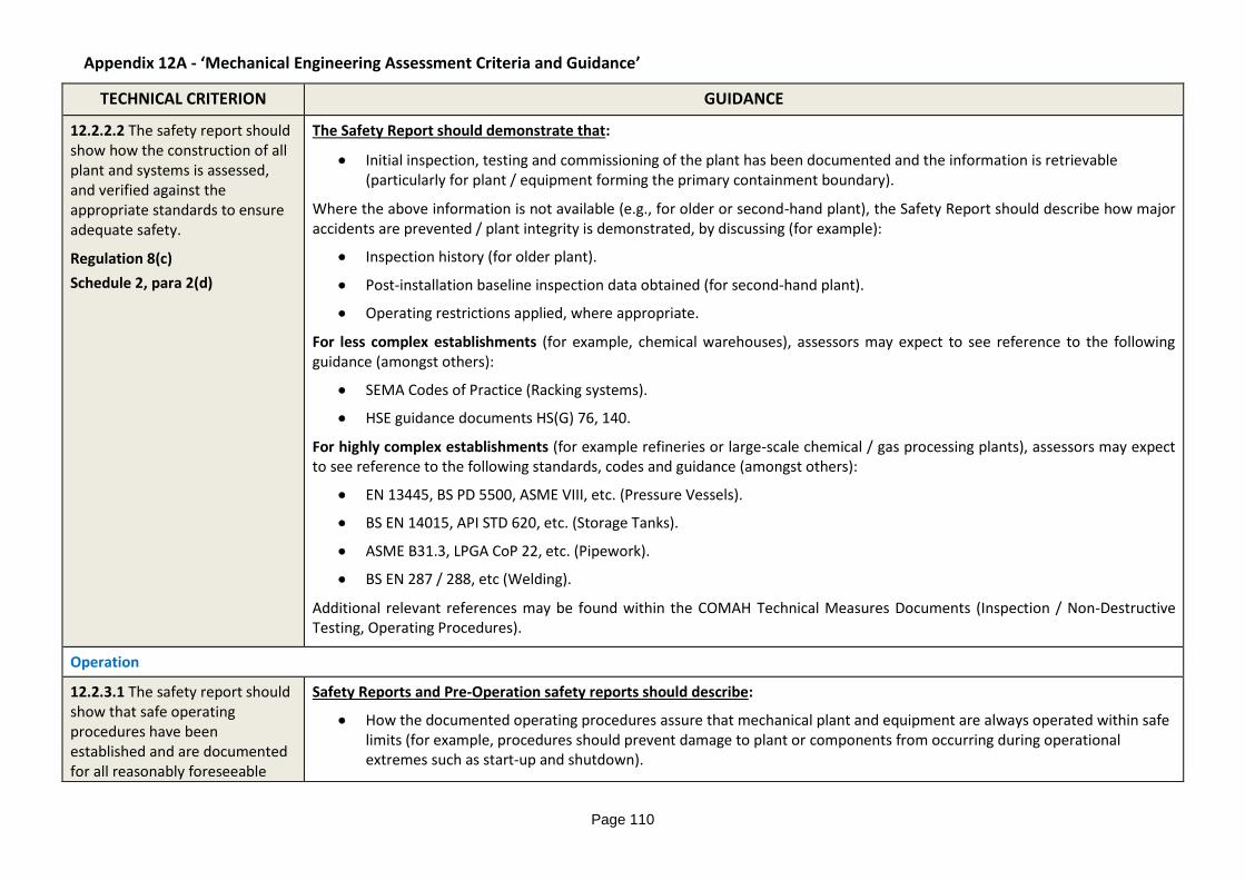
12.2.2.2 The safety report should show how the construction of all plant and systems is assessed, and verified against the appropriate standards to ensure adequate safety.
Regulation 8(c)
Schedule 2, para 2(d)
The Safety Report should demonstrate that:
Initial inspection, testing and commissioning of the plant has been documented and the information is retrievable (particularly for plant / equipment forming the primary containment boundary).
Where the above information is not available (e.g., for older or second-hand plant), the Safety Report should describe how major accidents are prevented / plant integrity is demonstrated, by discussing (for example):
Inspection history (for older plant).
Post-installation baseline inspection data obtained (for second-hand plant).
Operating restrictions applied, where appropriate.
For less complex establishments (for example, chemical warehouses), assessors may expect to see reference to the following guidance (amongst others):
SEMA Codes of Practice (Racking systems).
HSE guidance documents HS(G) 76, 140.
For highly complex establishments (for example refineries or large-scale chemical / gas processing plants), assessors may expect to see reference to the following standards, codes and guidance (amongst others):
EN 13445, BS PD 5500, ASME VIII, etc. (Pressure Vessels).
BS EN 14015, API STD 620, etc. (Storage Tanks).
ASME B31.3, LPGA CoP 22, etc. (Pipework).
BS EN 287 / 288, etc (Welding).
Additional relevant references may be found within the COMAH Technical Measures Documents (Inspection / Non-Destructive Testing, Operating Procedures).
Operation
12.2.3.1 The safety report should show that safe operating procedures have been established and are documented for all reasonably foreseeable
Safety Reports and Pre-Operation safety reports should describe:
How the documented operating procedures assure that mechanical plant and equipment are always operated within safe limits (for example, procedures should prevent damage to plant or components from occurring during operational extremes such as start-up and shutdown).
Appendix 12A - ‘Mechanical Engineering Assessment Criteria and Guidance’
Page 111
TECHNICAL CRITERION GUIDANCE
conditions.
Regulation 8(c)
Schedule2 para 2(c)
Schedule3 para 4(b)
For highly complex establishments (for example refineries or large-scale chemical plants), assessors may expect to see reference to the following codes and guidance (amongst others):
API RP 751 (Safe operation of HF alkylation units).
HS(G) 143 (Designing and operating safe chemical reaction processes).
Additional relevant references may be found within the COMAH Technical Measures Documents (Operating Procedures).
[Note: Process control systems (where installed) are covered under criterion 12.2.1.8 above.]
Maintenance
12.2.4.1 The safety report should show that an appropriate maintenance scheme is established for plant and systems to prevent major accidents or reduce the loss of containment in the event of such accidents.
Regulation 8(c)
Schedule 2 Para 2(c)
This criterion is not applicable to pre-construction reports.
The Safety Report should describe:
The maintenance administration system. Relevant job descriptions, roles and responsibilities (including a department organogram, if appropriate).
The maintenance regime adopted for safety critical plant items (i.e., evidence of a suitable proactive (planned, preventative) maintenance regime).
Systems for periodically reviewing the suitability of the maintenance regime adopted (based on findings/failure history).
The maintenance philosophy adopted for mechanical plant and equipment (e.g., time / condition / reliability based, etc).
Systems for prioritising maintenance activities (particularly in relation to safety critical plant).
Content provided in the Safety Report to assist demonstration could include:
Details of the personnel completing key mechanical maintenance activities on site (i.e., company employees, external contractors) and an overview of competency requirements.
Example(s) of safety critical maintenance activities completed on mechanical equipment (e.g., bench testing of pressure relief devices).
Examples illustrating the performance monitoring procedures applicable to the maintenance system (e.g., KPI’s / PSPI’s), including confirmation that data is periodically reviewed by senior management.
Where applicable, assessors may expect to see reference to the following standards, codes and guidance (amongst others):
HSE Ageing Plant Delivery Guide
Appendix 12A - ‘Mechanical Engineering Assessment Criteria and Guidance’
Page 112
TECHNICAL CRITERION GUIDANCE
HS(G) 28 (Bulk chlorine storage)
HS(G) 176 (Bulk flammables storage)
HS(G) 235 (Bulk acid storage)
HS(G) 254 (PSPI’s)
LPGA CoP 1, Part 3 (Periodic inspection and testing)
API Std 689 / ISO 14224 (Reliability and maintenance data)
Additional relevant references may be found within the COMAH Technical Measures Documents (Maintenance procedures, Reliability of utilities).
12.2.4.2 The safety report should describe appropriate procedures for maintenance that take account of any hazardous conditions within the working environment.
Regulation 8(c) Schedule 2 paras 2 (a) and (c)
The Safety Report should include:
An overview of the mechanical isolation practices adopted on site, prior to completing intrusive activities on plant or equipment containing hazardous substances (including steam).
[Note: Assessment should focus on potential major accident hazards. Concerns relating to particular hazardous activities may be addressed within the COMAH Intervention Plan.]
A description of how the mechanical isolation procedures fit into the overall maintenance management procedures (e.g., permit-to-work system) adopted on site.
Assessors may expect to see reference to the following codes and guidance (amongst others):
HS(G) 250 (PTW systems)
HS(G) 253 (Isolation of plant and equipment)
EEMUA 184 (Guide to the Isolation of Pressure Relieving Devices)
DSEAR
Additional relevant references may be found within the COMAH Technical Measures Documents (Hazardous Area Classification / Flame-proofing, Maintenance Procedures, Permit to Work Systems).
12.2.4.3 The safety report should show that systems are in place to ensure that safety critical plant and systems are examined at
This criterion is concerned with in-service integrity of safety critical plant and is not applicable to pre-construction reports.
[Note: Pre-Construction / Pre-Operation reports should, however, include a demonstration that a suitable Written Scheme of Examination is in place (and initial inspection by the Competent Person complete) prior to introducing pressurised hazardous
Appendix 12A - ‘Mechanical Engineering Assessment Criteria and Guidance’
Page 113
TECHNICAL CRITERION GUIDANCE
appropriate intervals by a competent person.
Regulation 8(c)
Schedule 2 para 2(c)
substances on site.]
The Safety Report should describe:
The periodic in-service examination regimes adopted for all plant containing hazardous fluids – to include pressurised and atmospheric systems, pipework etc.
The procedures for analysing inspection findings and confirming that safety critical plant is endorsed for a period of operating service (before the next examination is required). The role of external accredited organisations should also be described, where employed.
How inspection regimes and schemes of examination are reviewed to ensure that they remain suitable and sufficient
Content provided in the Safety Report to assist demonstration could include:
Systems for the prioritisation of safety critical equipment.
Independence and competence of inspection staff (e.g., by reference to UKAS accreditation, relevant industry standards) or compliance with BS EN ISO/IEC 17020.
Justification of inspection scope and frequencies by reference to relevant industry standards (where appropriate) and to analysis of inspection findings.
Appropriate systems for managing follow-up actions resulting from periodic inspection.
Where Risk Based Inspection (RBI) is employed, the Safety Report should show:
that the RBI assessment team contains the experience and knowledge required for a suitable and sufficient analysis.
that a thorough and systematic process is employed for identifying all relevant degradation mechanisms and likely sites (referencing relevant industry guidance, where appropriate).
that a suitably cautious approach is taken to changes in inspection frequency indicated by the RBI process, with the Competent Person involved in any modification to the schemes of examination.
[Note: The approach to integrity management adopted should reflect the complexity of the plant and the potential severity of the consequences of failure.]
For less complex establishments (for example, whisky distilleries / chemical warehouses), assessors may expect to see reference to the following guidance (amongst others):
SEMA Codes of Practice (Racking inspection), etc.
Appendix 12A - ‘Mechanical Engineering Assessment Criteria and Guidance’
Page 114
TECHNICAL CRITERION GUIDANCE
EEMUA 231 / SAFed IMG1 (Periodic examination and testing)
For highly complex establishments (for example refineries or large-scale chemical / gas processing plants), assessors may expect to see reference to the following standards, codes and guidance (amongst others):
HID Semi Permanent Circulars - Technical General;
SPC/TECH/GEN/18 (CUI) SPC/TECH/GEN/35 (Storage tank integrity) SPC/TECH/GEN/46 (RBI) SPC/TECH/GEN/47 (Pipework integrity)
HSE Ageing Plant Delivery Guide
HSE Guidance Note PM75 (GRP tanks and vessels)
HS(G) 176 (Storage of flammable liquids in tanks)
HS(G) 235 (Bulk storage of acids)
API 570 (Piping inspection)
API RP 571 (Damage mechanisms)
API RP 572 (Inspection of pressure vessels)
API 579-1 / ASME FFS-1 (Fitness-For-Service)
API RP 581 (RBI)
BS EN ISO 9712 (NDT)
BS ISO 55000 (Asset Management)
EEMUA 159, API 653 (Storage tank inspection)
LPGA CoP 1
PSSR
PUWER
Additional relevant references may be found within the COMAH Technical Measures Documents (Inspection / NDT)
Modifications
Appendix 12A - ‘Mechanical Engineering Assessment Criteria and Guidance’
Page 115
TECHNICAL CRITERION GUIDANCE
12.2.5.1 The safety report should show the system in place for ensuring modifications are adequately conceived, designed, installed and tested.
Regulation 8(c)
Schedule 2 Para 2(d)
Pre-Construction, Pre-Operation and Modification reports should describe:
The system in place for identifying and managing modifications during the design and construction phases of new builds / major plant modification projects.
[Note: The above process may be implemented by the principle design / construction contractor and may differ from the change management procedure ultimately adopted by the establishment’s operator, following project ‘handover’.]
The Safety Report should demonstrate:
How the establishment’s modification procedure covers changes to existing plant and mechanical equipment.
How the potential impact of new equipment on existing systems is assessed.
Technical approval processes for proposed modifications (demonstration that the concept has been properly addressed for mechanical integrity).
Post-construction / implementation review (confirmation that the design intent of the modification has been met).
Procedures for integrating new plant and equipment within existing integrity management arrangements.
Relevant guidance may be found within the COMAH Technical Measures Documents (Plant modification / change procedures).