Embed Size (px)
Citation preview
LUND UNIVERSITY
PO Box 117221 00 Lund+46 46-222 00 00
Mechanical embodiment design with digital desktops
Motte, Damien; Eriksson, Martin; Bjärnemo, Robert
Published in:Interactive Tables Workshop at the 19th AFIHM Conference
2007
Document Version:Publisher's PDF, also known as Version of record
Link to publication
Citation for published version (APA):Motte, D., Eriksson, M., & Bjärnemo, R. (2007). Mechanical embodiment design with digital desktops. In O.Delerue, & C. Agon (Eds.), Interactive Tables Workshop at the 19th AFIHM Conference (Vol. Appendix, pp. 31-34). Association for Computing Machinery (ACM).
Total number of authors:3
General rightsUnless other specific re-use rights are stated the following general rights apply:Copyright and moral rights for the publications made accessible in the public portal are retained by the authorsand/or other copyright owners and it is a condition of accessing publications that users recognise and abide by thelegal requirements associated with these rights. • Users may download and print one copy of any publication from the public portal for the purpose of private studyor research. • You may not further distribute the material or use it for any profit-making activity or commercial gain • You may freely distribute the URL identifying the publication in the public portal
Read more about Creative commons licenses: https://creativecommons.org/licenses/Take down policyIf you believe that this document breaches copyright please contact us providing details, and we will removeaccess to the work immediately and investigate your claim.

Mechanical Embodiment Design with Digital Desktops
Damien Motte, Martin Eriksson, Robert Bjärnemo Div. of Machine at Dept. of Design Sciences LTH
Lund University P.O. Box 118
221 00 Lund, Sweden {damien.motte, martin.eriksson, robert.bjarnemo}@mkon.lth.se
RÉSUMÉ Cette contribution décrit l’aide potentielle que le concept de table interactive apporte à certaines tâches du concep-teur en mécanique. Le travail de recherche présenté n’en est qu’à sa genèse. La problématique est la suivante : une fois la faisabilité d’une idée de produit (le concept) est prouvée, le concepteur développe l’architecture et les composants du produit (embodiment design). À ce ni-veau, l’esquisse joue un rôle prépondérant tant au niveau créatif qu’au niveau de l’analyse (calculs). D’autre part le concepteur doit communiquer très souvent avec les ingénieurs de production. Les outils actuels de concep-tion assistée par ordinateur (CAO) ne donnent pas la même liberté, la même sensibilité, ni la même possibilité de communication et de compréhension que l’esquisse. La table interactive dans ce domaine-là se présente comme une solution technique qui prend en compte la majorité des besoins du concepteur.
MOTS CLÉS : conception mécanique, esquisse, table in-teractive, collaboration colocalisée et à distance, expéri-mentations, usage, besoin.
ABSTRACT This paper describes the potential help that the interac-tive desktop concept can bring to the execution of em-bodiment design tasks. The presented project is still in its infancy. The research framework is the following: once a product concept has been approved, the mechani-cal design engineer develops the product architecture and product part (also called embodiment design). Sketches at that level are essential both for synthesis and analysis purposes. Moreover, the designer has often to collaborate with the production department. The current CAD tools do not allow the same freedom, sensitivity nor the same possibility of communication and under-standing the sketch. The interactive desktop is a techni-cal mean that would allow taking into account the major-ity of the mechanical design engineer needs during em-bodiment design.
KEYWORDS: mechanical engineering design, sketch, in-teractive desktop, co-located and remote collaboration, experiments, use, needs, mechanical analysis.
CATEGORIES AND SUBJECT DESCRIPTORS: H.5.2 [Information Interfaces and Presentation]: User Inter-faces; H.1.2 [Models and Principles]: User/Machine Sys-tems.
GENERAL TERMS: Human Factors, Design
INTRODUCTION There are many moments during the mechanical engi-neering design activity that still rely on plain pen and paper – it is still the quickest and least intrusive way to develop one’s design. In this contribution, we describe these moments for the embodiment design phase of the mechanical engineering design process, and the service interactive desktops can bring to facilitate the design en-gineer’s work.
In the first section, the embodiment design phase is pre-sented. Then the ways interactive desktops could help the design engineer by fulfilling his/her needs and over-come certain related issues are presented, ways that re-main to be implemented.
EMBODIMENT DESIGN The mechanical engineering design process is usually presented as a three-phased process: conceptual design, embodiment design, and detail design [1]. During the conceptual design phase, the mechanical design engineer develops new ideas, new principles of solution based on physical principles and evaluate their feasibility. Once an idea (a concept) has been chosen, the product archi-tecture and product part development starts. This phase is the embodiment design phase, illustrated by an exam-ple Figure 1. Finally, during the detail design phase, the product is carefully analyzed by means of analysis tools (Finite Element-based tools mainly) and simulation sys-tems, is adapted to production requirements and docu-mentation is compiled.
Of these three phases, embodiment design is treated like a poor relation in the engineering design community. Lots of efforts a put towards conceptual design, because the problems at this level are ill defined, thus complex, and because the actions and decisions impact the whole remaining of the product development process.
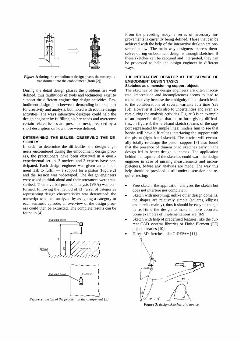
Figure 1: during the embodiment design phase, the concept is transformed into the embodiment (from [2]).
During the detail design phases the problems are well defined, thus multitudes of tools and techniques exist to support the different engineering design activities. Em-bodiment design is in-between, demanding both support for creativity and analysis, but mixed with routine design activities. The ways interactive desktops could help the design engineer by fulfilling his/her needs and overcome certain related issues are presented next, preceded by a short description on how those were defined.
DETERMINING THE ISSUES: OBSERVING THE DE-SIGNERS In order to determine the difficulties the design engi-neers encountered during the embodiment design proc-ess, the practitioners have been observed in a quasi-experimental set-up. 3 novices and 3 experts have par-ticipated. Each design engineer was given an embodi-ment task to fulfill — a support for a piston (Figure 2) and the session was videotaped. The design engineers were asked to think aloud and their utterances were tran-scribed. Then a verbal protocol analysis (VPA) was per-formed, following the method of [3]: a set of categories representing design characteristics was determined; the transcript was then analyzed by assigning a category to each semantic episode; an overview of the design proc-ess could then be extracted. The complete results can be found in [4].
Hydraulic piston
1100
Hydraulic piston
Ground
450
400
F = 90 kN
Installation
Figure 2: Sketch of the problem in the assignment [5].
From the preceding study, a series of necessary im-provements is currently being defined. Those that can be achieved with the help of the interactive desktop are pre-sented below. The main way designers express them-selves during embodiment design is through sketches. If these sketches can be captured and interpreted, they can be processed to help the design engineer in different ways.
THE INTERACTIVE DESKTOP AT THE SERVICE OF EMBODIMENT DESIGN TASKS Sketches as dimensioning support objects The sketches of the design engineers are often inaccu-rate. Imprecision and incompleteness seems to lead to more creativity because the ambiguity in the sketch leads to the considerations of several variants at a time (see [6]). However it leads also to uncertainties and even er-rors during the analysis activities. Figure 3 is an example of an imprecise design that led to form giving difficul-ties. In figure 3, the left-hand sketch (beams of the sup-port represented by simple lines) hinders him to see that he/she will have difficulties interfacing the support with the piston (right-hand sketch). The novice will eventu-ally totally re-design the piston support [7] also found that the presence of dimensioned sketches early in the design led to better design outcomes. The application behind the capture of the sketches could warn the design engineer in case of missing measurements and incom-pleteness, before any analyses are made. The way this help should be provided is still under discussion and re-quires testing:
• Free sketch: the application analyses the sketch but does not interfere nor complete it.
• Sketch with morphing: unlike other design domains, the shapes are relatively simple (squares, ellipses and circles mainly), thus it should be easy to change in real-time the design to make it more accurate. Some examples of implementations are [8-9].
• Sketch with help of predefined features, like the cur-rent CAD systems libraries or Finite Element (FE) object libraries [10].
• Direct 3D sketches, like GiDES++ [11].
Figure 3: design sketches of a novice.

Sketches as support of reflection The sketches are made mainly in 2D, probably because the design engineers are educated to sketch using the standards of technical drawings. However they use 3D sketches in order to get an overview of the design prob-lem or for explanation purpose. 3D sketch could be ex-tracted from the 2D sketches as the application EsQUIsE [12] does for architectural sketches.
Reuse of existing elements During embodiment design, some parts of the sketches are existing components or previously design product parts. These could be retrieved by the application, either by classic text-based database query or by sketch-based database query [13]. If the elements come from CAD systems or FE-libraries, they have to be transformed to be compatible to the sketch application (like imple-mented in EsQUIsE).
Exploitation of the sketches for synthesis There exists a large set of basic rules, guidelines, and principles at the service of the design engineer during the embodiment design activity. A whole body of such knowledge can be found in [1]. These help the designer during the creative part of embodiment design (or syn-thesis) and their implementation would assist the him/her to design right from the start. However these basic rules, guidelines, and principles would be very difficult to im-plement because most of them are qualitative in nature. The most quantitative of them are already implemented in diverse expert systems, like the Molding Advisor [14]
Exploitation of the sketches for analysis The usual procedure employed by the design engineer is to re-draw the sketched design into an analysis tool such as ANSYS or SIMULIA. This implies a huge loss of time and flexibility: 1) the original sketch already exists; 2) it takes more time to draw in those systems; the re-sults can lead to dramatic changes that lead to new pen-and-paper designs not initially present in the sketch. With an electronic sketch, most of these activities could be semi- or totally automated. This has been tested suc-cessfully with the sketch-recognition module of the software EsQUIsE from Lucid Group [12] and ANSYS. Figure 4 shows a shear stress analysis of a handmade beam. Figure 5 displays the potential modification to the beam after a topology optimization. The blue areas are those that are possible to cut away from the beam in or-der to reduce the weight. This gives the designer indica-tions of potential areas of material reduction under the given loading situation.
The main areas of analysis would be structure analysis, thermal analysis and some specific parameter studies and optimizations. These analyses concern of course rela-tively simple designs in a routine design process and are not intended, in the current state, to replace dedicated systems. [15] describes how analysis could be carried at
the embodiment design phase. The results could be ei-ther applied directly to the sketch or presented to the de-sign engineer as decision support.
Figure 4: Original sketch (beam below) and result of the struc-
tural analysis in ANSYS (above) imported into EsQUIsE
Figure 5: Potential modification of the original sketch based on result from analysis in ANSYS and imported into EsQUIsE
Collaboration and multimodality Even if the design engineer works mostly alone during the embodiment design phase, his sketches and calcula-tions are presented to other design engineers working on other parts of the same product, to production engineers and even sometimes to marketers. Nowadays, the teams are scattered around the world and interactive desktops are one of the interfaces that will allow real-time discus-sions and modifications. No investigations on that area related to embodiment design have been found in the lit-erature though. Multimodality has not been studied for embodiment design so far, but even if the design engi-neer works alone, gestures probably would help the ap-plication “guessing” what the design engineer’s inten-tions are. Such a study can be found at [16].
IMPLEMENTATION The division of Machine Design at Lund University is a part of the International Virtual Design Network pre-sided by Lucid Group at Liège University (http://www.arch.ulg.ac.be/Lucid/Ressources_Virtual_desktops.php). The interactive desktops used are the Inter-active Whiteboard of the Prometheus Company together with two projectors so as to have a resolution sufficient enough to give the sketches the same appearance as pen-and-paper ones (Figure 6). A Wacom Cintiq tablet, a tablet PC and electronic paper are also available at the division for testing their adequacy as sketch and design support tools in comparison with the interactive desktop.

Figure 6: The interactive desktop system at Lund University
As the last section showed, the application needed for design engineers would not require many novel concepts for the use of the interactive desktops (The sketch rec-ognition and interpretation of a 3D object with an in-complete sketch would be an AI challenge though.) It is rather a gathering of already implemented solutions, but the range of problems is of great importance for the in-dustry. The architecture of an application that would cor-respond to the description of the last section would be similar to the generic architecture of EsQUIsE [12] con-cept developed by Lucid Group and should be developed in co-operation with this laboratory. It would consist of a stroke recognition module, a multi-agent-based interpre-tation module, and from there other different modules would be coupled (error-controlling module, links to simulations systems, etc.).
CONCLUSION This contribution presented some of the current issues faced by the design engineer during the embodiment de-sign phase and the service that an interactive desktop could bring: 1) an interface that is non-intrusive, without any interferences (i.e. respecting the cognitive limita-tions of the designers and the constraints of his/her working environment), yet facilitating his/her daily ac-tivity; 2) a guiding and decision support thanks to the links between the sketching tool and mechanical analysis and synthesis support systems.
ACKNOWLEDGMENTS The interactive whiteboard and related equipment have been financed by the Maja och Eriks Lindqvist’s Foun-dation. The authors are also grateful to Prof. Pierre Le-clercq and the Lucid Group at Liège University for their comments and the permission to use EsQUIsE.
BIBLIOGRAPHY 1. Pahl, G. and Beitz, W. Engineering Design (2nd
Ed.). Spring, London, 1996.
2. VDI. VDI Guideline 2223: Systematic Embodiment Design of Technical Products. Beuth, Berlin, 2003.
3. Ericsson, K.A., and Simon, H.A., Protocol Analysis – Verbal Reports as Data (Rev. Edition). MIT Press: Cambridge, MA, 1993.
4. Motte, D. On Synthesis in the Later Phases of the Mechanical Engineering Design Process. Licentiate thesis. Lund University, Lund, 2006.
5. Motte, D., Andersson, P.-E., and Bjärnemo, R. Study of the Designer’s Cognitive Processes During the Later Phases of the Engineering Design Process. In Proceedings of the Design 2004, (2004, Dubrovnik), pp. 421-428.
6. Kavakli, M. & Gero, J.S. The structure ofconcurrent cognitive actions: a case study on novice and expert designers, Design Studies, Vol. 23, No.1, 2002, pp. 25-40.
7. M. C. Yang, Concept Generation and Sketching: Correlations with Design Outcome. In Proceedings of DETC/DTM (2003, Chicago).
8. Arvo, J. And Novins, K. Fluid Sketches: Continu-ous Recognition and Morphing of Sinmple Hand-Drawn Shapes. CHI Letters, Vol. 2, No. 3, 2000, pp. 73-80.
9. Igarashi, T., Matsuoka, S., Kawachiya, S., and Ta-naka, H. Interactive Beautification: A Technique for Rapid Geometric Design. In ACM UIST'97, (Octo-ber 14-17, 1997, Banff, Canada), pp. 105-114.
10. Burman, Å. And Eriksson, M. Development of a modelling tool for Collaborative Finite Element Analysis. In 2002 Ansys Conference Proceedings, (2002, Pittsburgh, PA).
11. Pereira, J.P., Jorge, J.A., Branco,V.A., Silva,N.F., and Cardoso, F.N. Cascading Recognizers for Am-biguous Calligraphic Interaction. In Eurographics Workshop on Sketch-Based Interfaces and Modeling (September 2004, Grenoble), pp. 63-72.
12. Leclercq, P. and Juchmes, R. The Absent Interface in Design. Artificial Intelligence for Engineering Design, Analysis and Manufacturing, Vol 16 No. 3, 2002, pp. 219-227.
13. Fonseca, M.J., Ferreira, A., and Jorge, J.A. Towards 3D Modeling using Sketches and Retrieval. In Eu-rographics Workshop on Sketch-Based Interfaces and Modeling (September 2004, Grenoble), pp. 128-136.
14. Lockett, H. and Guenov, M. A Knowledge-Based Expert System for Moulded Part Design. In Pro-ceeding of International Conference on Engineering Design, ICED’07 (August 28-31 2007, Paris).
15. Eriksson, M. and Burman, Å. Improving the design process by integrating Design analysis. In Proceed-ings of the International Conference on Engineering Design ICED’05 (August, 2005, Melbourne).
16. Leclercq P., Martin G., Deshayes C., Guena F. Vers une interface multimodale pour une assistance à la conception architecturale. In 16ième Conférence Francophone sur l’Interaction Homme-Machine (2004, Namur, Belgium).