Embed Size (px)
Citation preview
(English) DM-BR0009-00
BR-CX77BR-CX75BR-R517BR-R515BR-R317BR-R315
Dealer's Manual
ROAD MTB Trekking
City Touring/ Comfort Bike
URBAN SPORT E-BIKE
Mechanical Disc Brakes
2
CONTENTS
IMPORTANT NOTICE .............................................................................................. 3
TO ENSURE SAFETY ............................................................................................... 4
LIST OF TOOLS TO BE USED .................................................................................. 8
INSTALLATION ..................................................................................................... 10Installation of the calipers .........................................................................................................................10
ADJUSTMENT ...................................................................................................... 17Adjustment when the brake pads are worn ............................................................................................17
Checking brake pad clearance and replacement timing .........................................................................19
MAINTENANCE .................................................................................................... 21Replacing the brake pads ..........................................................................................................................21
3
IMPORTANT NOTICE
IMPORTANT NOTICE
• This dealer’s manual is intended primarily for use by professional bicycle mechanics. Users who are not professionally trained for bicycle assembly should not attempt to install the components themselves using the dealer’s manuals. If any part of the information on the manual is unclear to you, do not proceed with the installation. Instead, contact your place of purchase or a local bicycle dealer for their assistance.
• Make sure to read all instruction manuals included with the product.
• Do not disassemble or modify the product other than as stated in the information contained in this dealer’s manual.
• All dealer’s manuals and instruction manuals can be viewed on-line on our website (http://si.shimano.com).
• Please observe the appropriate rules and regulations of the country, state or region in which you conduct your business as a dealer.
For safety, be sure to read this dealer’s manual thoroughly before use, and follow it for correct use.
The following instructions must be observed at all times in order to prevent personal injury and physical damage to equipment and surroundings.The instructions are classified according to the degree of danger or damage which may occur if the product is used incorrectly.
DANGER
Failure to follow the instructions will result in death or serious injury.
WARNING
Failure to follow the instructions could result in death or serious injury.
CAUTION
Failure to follow the instructions could cause personal injury or physical damage to equipment and surroundings.
4
TO ENSURE SAFETY
TO ENSURE SAFETY
WARNING
• Be sure to follow the instructions provided in the manuals when installing the product.It is recommended to use genuine Shimano parts only. If parts such as bolts and nuts become loose or damaged, the bicycle may suddenly fall over, which may cause serious injury.In addition, if adjustments are not carried out correctly, problems may occur, and the bicycle may suddenly fall over, which may cause serious injury.
• Be sure to wear safety glasses or goggles to protect your eyes while performing maintenance tasks such as replacing parts.
• After reading the dealer's manual thoroughly, keep it in a safe place for later reference.
Be sure to also inform users of the following:
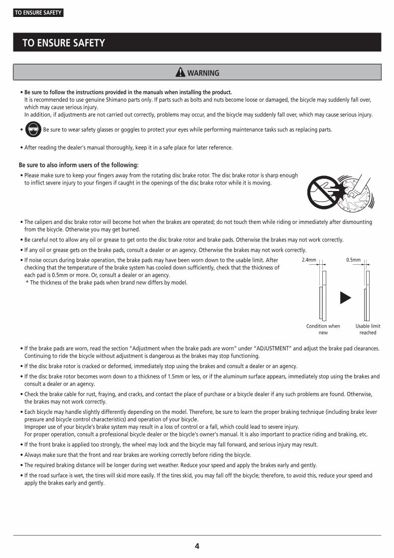
• Please make sure to keep your fingers away from the rotating disc brake rotor. The disc brake rotor is sharp enough to inflict severe injury to your fingers if caught in the openings of the disc brake rotor while it is moving.
• The calipers and disc brake rotor will become hot when the brakes are operated; do not touch them while riding or immediately after dismounting from the bicycle. Otherwise you may get burned.
• Be careful not to allow any oil or grease to get onto the disc brake rotor and brake pads. Otherwise the brakes may not work correctly.
• If any oil or grease gets on the brake pads, consult a dealer or an agency. Otherwise the brakes may not work correctly.
• If noise occurs during brake operation, the brake pads may have been worn down to the usable limit. After checking that the temperature of the brake system has cooled down sufficiently, check that the thickness of each pad is 0.5mm or more. Or, consult a dealer or an agency.* The thickness of the brake pads when brand new differs by model.
2.4mm 0.5mm
Usable limit reached
Condition when new
• If the brake pads are worn, read the section “Adjustment when the brake pads are worn” under “ADJUSTMENT” and adjust the brake pad clearances. Continuing to ride the bicycle without adjustment is dangerous as the brakes may stop functioning.
• If the disc brake rotor is cracked or deformed, immediately stop using the brakes and consult a dealer or an agency.
• If the disc brake rotor becomes worn down to a thickness of 1.5mm or less, or if the aluminum surface appears, immediately stop using the brakes and consult a dealer or an agency.
• Check the brake cable for rust, fraying, and cracks, and contact the place of purchase or a bicycle dealer if any such problems are found. Otherwise, the brakes may not work correctly.
• Each bicycle may handle slightly differently depending on the model. Therefore, be sure to learn the proper braking technique (including brake lever pressure and bicycle control characteristics) and operation of your bicycle. Improper use of your bicycle's brake system may result in a loss of control or a fall, which could lead to severe injury. For proper operation, consult a professional bicycle dealer or the bicycle's owner's manual. It is also important to practice riding and braking, etc.
• If the front brake is applied too strongly, the wheel may lock and the bicycle may fall forward, and serious injury may result.
• Always make sure that the front and rear brakes are working correctly before riding the bicycle.
• The required braking distance will be longer during wet weather. Reduce your speed and apply the brakes early and gently.
• If the road surface is wet, the tires will skid more easily. If the tires skid, you may fall off the bicycle; therefore, to avoid this, reduce your speed and apply the brakes early and gently.
5
TO ENSURE SAFETY
For Installation to the Bicycle, and Maintenance:
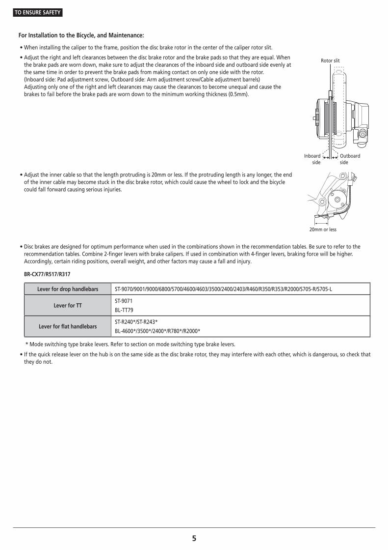
• When installing the caliper to the frame, position the disc brake rotor in the center of the caliper rotor slit.
• Adjust the right and left clearances between the disc brake rotor and the brake pads so that they are equal. When the brake pads are worn down, make sure to adjust the clearances of the inboard side and outboard side evenly at the same time in order to prevent the brake pads from making contact on only one side with the rotor. (Inboard side: Pad adjustment screw, Outboard side: Arm adjustment screw/Cable adjustment barrels) Adjusting only one of the right and left clearances may cause the clearances to become unequal and cause the brakes to fail before the brake pads are worn down to the minimum working thickness (0.5mm).
Rotor slit
Inboard side
Outboard side
• Adjust the inner cable so that the length protruding is 20mm or less. If the protruding length is any longer, the end of the inner cable may become stuck in the disc brake rotor, which could cause the wheel to lock and the bicycle could fall forward causing serious injuries.
20mm or less
• Disc brakes are designed for optimum performance when used in the combinations shown in the recommendation tables. Be sure to refer to the recommendation tables. Combine 2-finger levers with brake calipers. If used in combination with 4-finger levers, braking force will be higher. Accordingly, certain riding positions, overall weight, and other factors may cause a fall and injury.
BR-CX77/R517/R317
Lever for drop handlebars ST-9070/9001/9000/6800/5700/4600/4603/3500/2400/2403/R460/R350/R353/R2000/S705-R/S705-L
Lever for TTST-9071
BL-TT79
Lever for flat handlebarsST-R240*/ST-R243*
BL-4600*/3500*/2400*/R780*/R2000*
* Mode switching type brake levers. Refer to section on mode switching type brake levers.
• If the quick release lever on the hub is on the same side as the disc brake rotor, they may interfere with each other, which is dangerous, so check that they do not.
6
TO ENSURE SAFETY
�Mode switching type brake levers
• The brake levers are equipped with a mode switching mechanism which can be used to make them compatible with cantilever brakes and roller brakes or V-BRAKE brakes with power modulator.
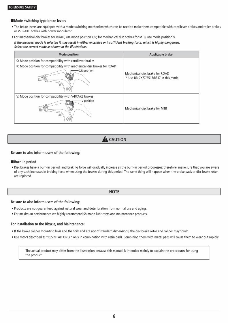
• For mechanical disc brakes for ROAD, use mode position C/R; for mechanical disc brakes for MTB, use mode position V.
If the incorrect mode is selected it may result in either excessive or insufficient braking force, which is highly dangerous. Select the correct mode as shown in the illustrations.
Mode position Applicable brake
C: Mode position for compatibility with cantilever brakes
R: Mode position for compatibility with mechanical disc brakes for ROADC/R position
Mechanical disc brake for ROAD* Use BR-CX77/R517/R317 in this mode.
V: Mode position for compatibility with V-BRAKE brakesV position
Mechanical disc brake for MTB
CAUTION
Be sure to also inform users of the following:
�Burn-in period • Disc brakes have a burn-in period, and braking force will gradually increase as the burn-in period progresses; therefore, make sure that you are aware of any such increases in braking force when using the brakes during this period. The same thing will happen when the brake pads or disc brake rotor are replaced.
NOTE
Be sure to also inform users of the following:
• Products are not guaranteed against natural wear and deterioration from normal use and aging.
• For maximum performance we highly recommend Shimano lubricants and maintenance products.
For Installation to the Bicycle, and Maintenance:
• If the brake caliper mounting boss and the fork end are not of standard dimensions, the disc brake rotor and caliper may touch.
• Use rotors described as “RESIN PAD ONLY” only in combination with resin pads. Combining them with metal pads will cause them to wear out rapidly.
The actual product may differ from the illustration because this manual is intended mainly to explain the procedures for using the product.
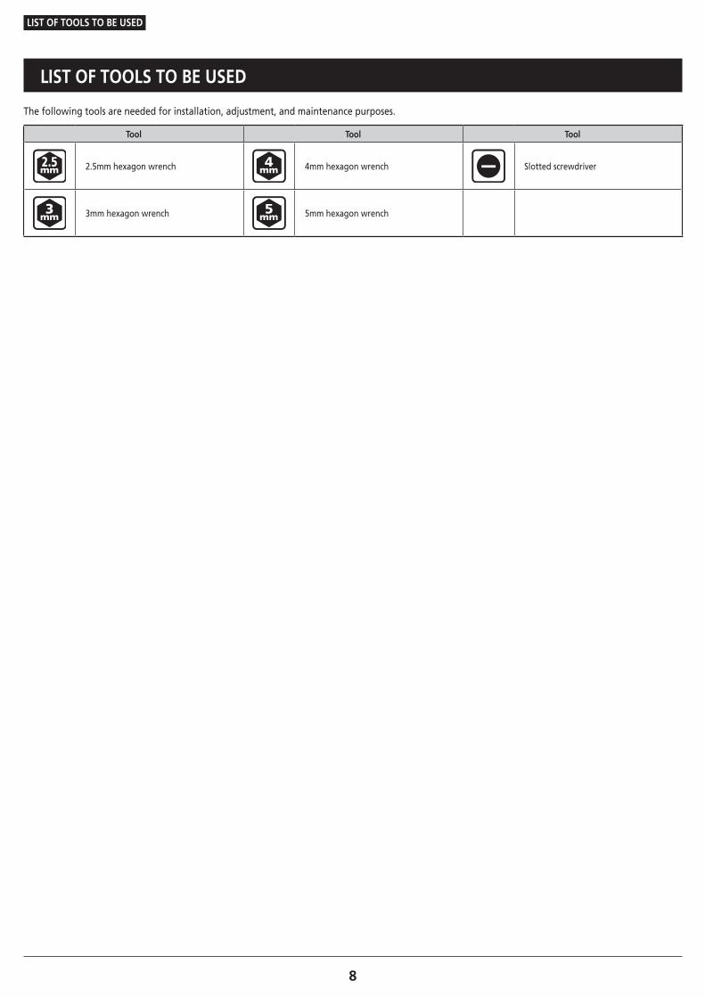
LIST OF TOOLS TO BE USED
8
LIST OF TOOLS TO BE USED
LIST OF TOOLS TO BE USED
The following tools are needed for installation, adjustment, and maintenance purposes.
Tool Tool Tool
2.5mm hexagon wrench 4mm hexagon wrench Slotted screwdriver
3mm hexagon wrench 5mm hexagon wrench
INSTALLATION
10To be continued on next page
INSTALLATION
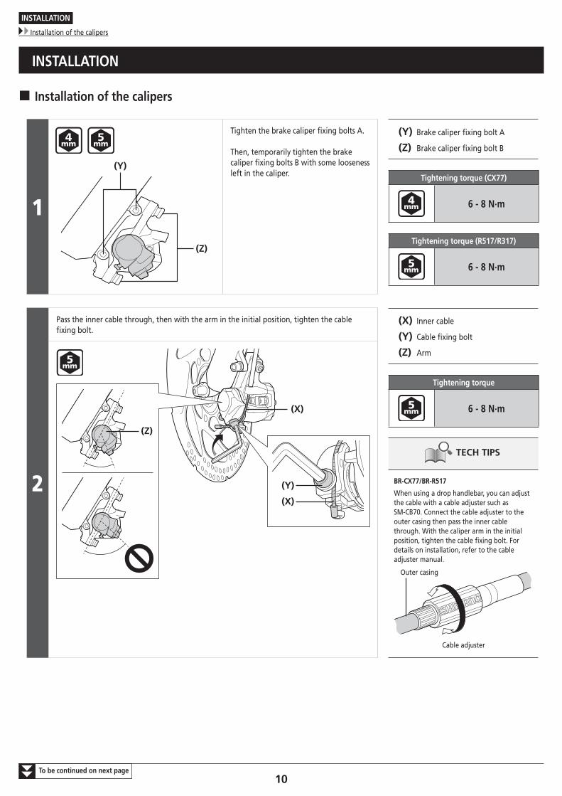
Installation of the calipers
INSTALLATION
� Installation of the calipers
1
(Z)
(Y)
Tighten the brake caliper fixing bolts A.
Then, temporarily tighten the brake caliper fixing bolts B with some looseness left in the caliper.
(Y) Brake caliper fixing bolt A
(Z) Brake caliper fixing bolt B
Tightening torque (CX77)
6 - 8 N·m
Tightening torque (R517/R317)
6 - 8 N·m
2
Pass the inner cable through, then with the arm in the initial position, tighten the cable fixing bolt.
(X) Inner cable
(Y) Cable fixing bolt
(Z) Arm
Tightening torque
6 - 8 N·m
TECH TIPS
BR-CX77/BR-R517
When using a drop handlebar, you can adjust the cable with a cable adjuster such as SM-CB70. Connect the cable adjuster to the outer casing then pass the inner cable through. With the caliper arm in the initial position, tighten the cable fixing bolt. For details on installation, refer to the cable adjuster manual.
Outer casing
Cable adjuster
(Y)
(X)
(Z)
(X)
11To be continued on next page
INSTALLATION
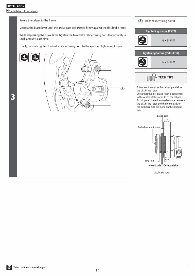
Installation of the calipers
3
Secure the caliper to the frame.
Depress the brake lever until the brake pads are pressed firmly against the disc brake rotor.
While depressing the brake lever, tighten the two brake caliper fixing bolts B alternately in small amounts each time.
Finally, securely tighten the brake caliper fixing bolts to the specified tightening torque.
(Z) Brake caliper fixing bolt B
Tightening torque (CX77)
6 - 8 N·m
Tightening torque (R517/R317)
6 - 8 N·m
TECH TIPS
This operation makes the caliper parallel to the disc brake rotor.Check that the disc brake rotor is positioned in the center of the rotor slit of the caliper.At this point, there is some clearance between the disc brake rotor and the brake pads on the outboard side but none on the inboard side.
Disc brake rotor
Brake pad
Rotor slit
Pad adjustment screw
Inboard side Outboard side
(Z)
12
INSTALLATION
Installation of the calipers
To be continued on next page
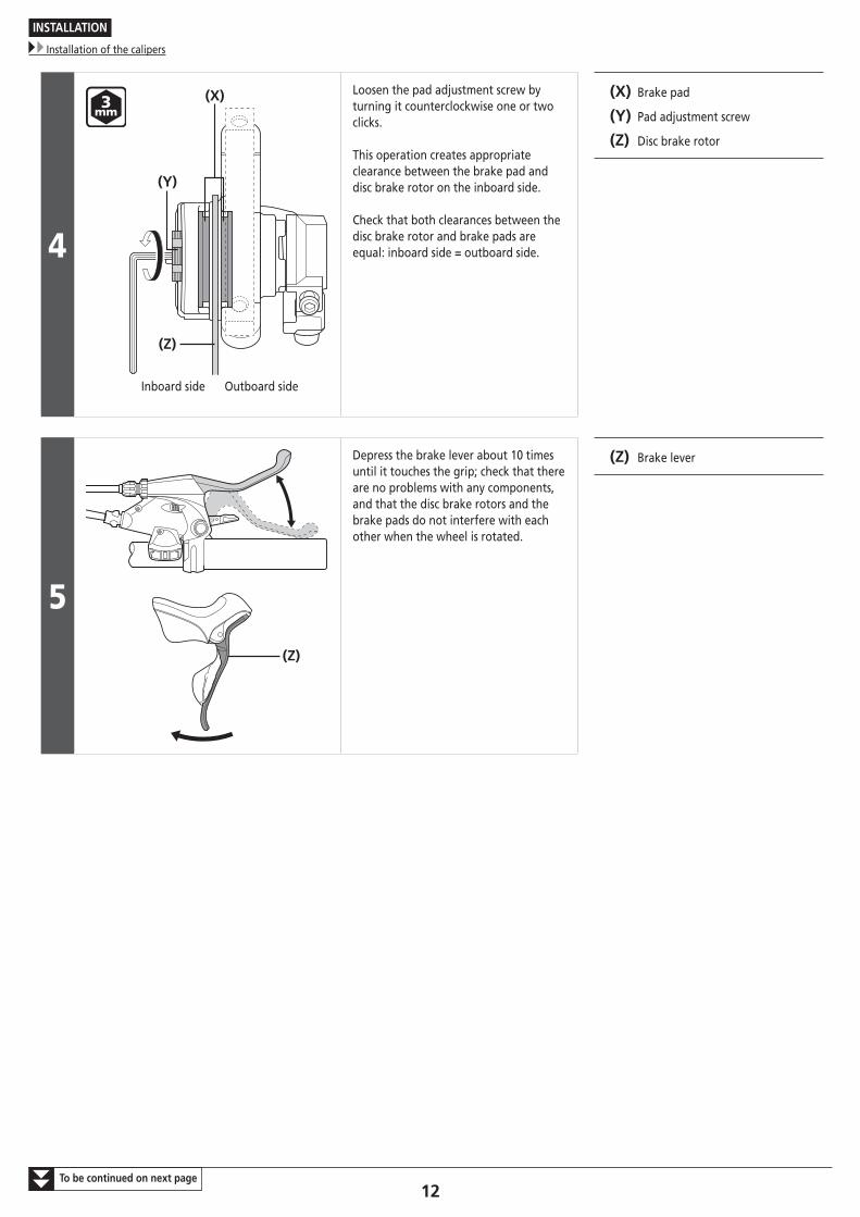
4
(Z)
(Y)
(X)
Inboard side Outboard side
Loosen the pad adjustment screw by turning it counterclockwise one or two clicks.
This operation creates appropriate clearance between the brake pad and disc brake rotor on the inboard side.
Check that both clearances between the disc brake rotor and brake pads are equal: inboard side = outboard side.
(X) Brake pad
(Y) Pad adjustment screw
(Z) Disc brake rotor
5(Z)
Depress the brake lever about 10 times until it touches the grip; check that there are no problems with any components, and that the disc brake rotors and the brake pads do not interfere with each other when the wheel is rotated.
(Z) Brake lever
13To be continued on next page
INSTALLATION
Installation of the calipers
6
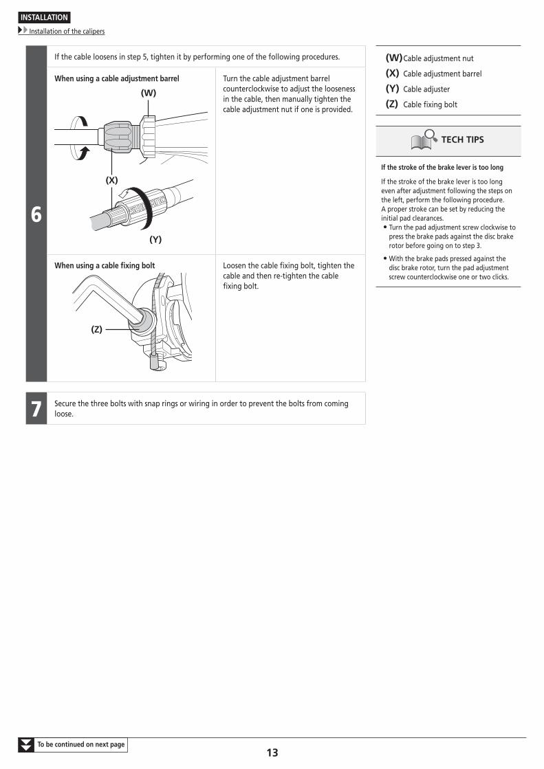
If the cable loosens in step 5, tighten it by performing one of the following procedures. (W) Cable adjustment nut
(X) Cable adjustment barrel
(Y) Cable adjuster
(Z) Cable fixing bolt
TECH TIPS
If the stroke of the brake lever is too long
If the stroke of the brake lever is too long even after adjustment following the steps on the left, perform the following procedure.A proper stroke can be set by reducing the initial pad clearances.
• Turn the pad adjustment screw clockwise to press the brake pads against the disc brake rotor before going on to step 3.
• With the brake pads pressed against the disc brake rotor, turn the pad adjustment screw counterclockwise one or two clicks.
When using a cable adjustment barrel
(Y)
(X)
(W)
Turn the cable adjustment barrel counterclockwise to adjust the looseness in the cable, then manually tighten the cable adjustment nut if one is provided.
When using a cable fixing bolt
(Z)
Loosen the cable fixing bolt, tighten the cable and then re-tighten the cable fixing bolt.
7 Secure the three bolts with snap rings or wiring in order to prevent the bolts from coming loose.
14To be continued on next page
INSTALLATION
Installation of the calipers
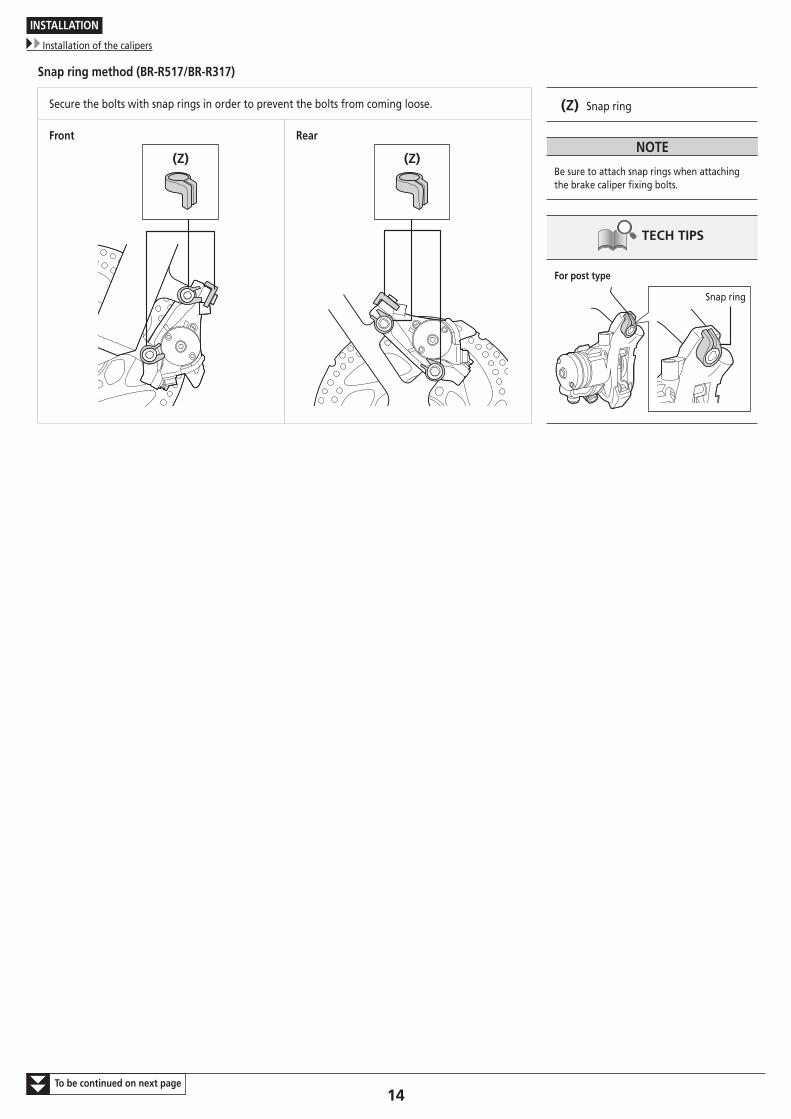
Snap ring method (BR-R517/BR-R317)
Secure the bolts with snap rings in order to prevent the bolts from coming loose. (Z) Snap ring
NOTE
Be sure to attach snap rings when attaching the brake caliper fixing bolts.
TECH TIPS
For post type
Snap ring
Front
(Z)
Rear
(Z)
15
INSTALLATION
Installation of the calipers
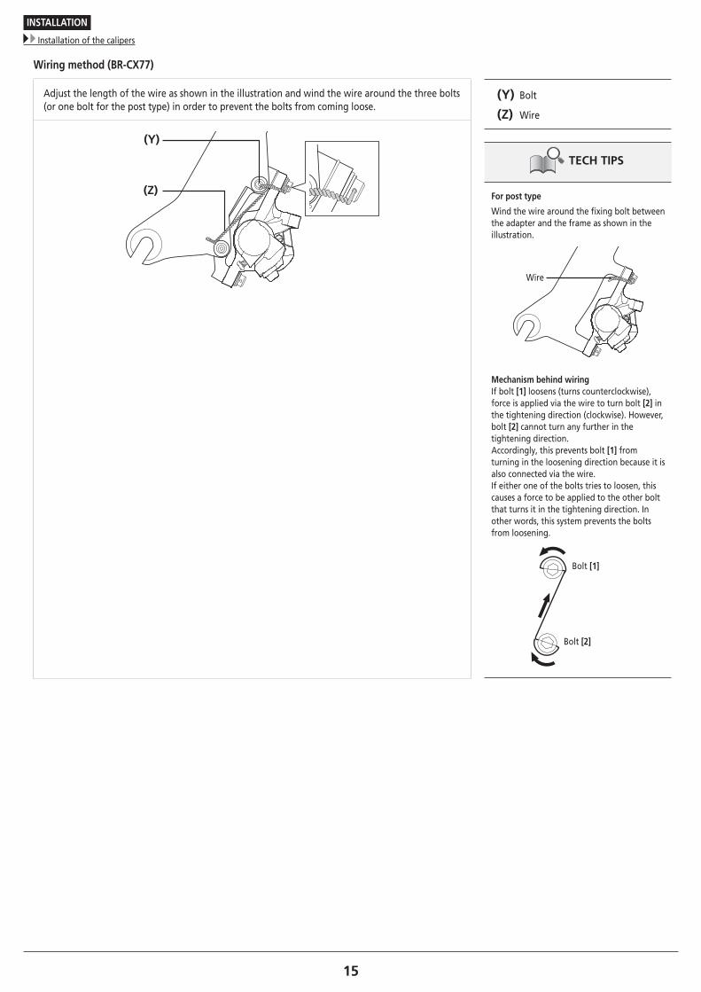
Wiring method (BR-CX77)
Adjust the length of the wire as shown in the illustration and wind the wire around the three bolts (or one bolt for the post type) in order to prevent the bolts from coming loose.
(Y) Bolt
(Z) Wire
TECH TIPS
For post type
Wind the wire around the fixing bolt between the adapter and the frame as shown in the illustration.
Wire
Mechanism behind wiringIf bolt [1] loosens (turns counterclockwise), force is applied via the wire to turn bolt [2] in the tightening direction (clockwise). However, bolt [2] cannot turn any further in the tightening direction.Accordingly, this prevents bolt [1] from turning in the loosening direction because it is also connected via the wire.If either one of the bolts tries to loosen, this causes a force to be applied to the other bolt that turns it in the tightening direction. In other words, this system prevents the bolts from loosening.
Bolt [1]
Bolt [2]
(Y)
(Z)
ADJUSTMENT
17
ADJUSTMENT
Adjustment when the brake pads are worn
ADJUSTMENT
� Adjustment when the brake pads are wornAdjust the clearances when the brake pads are worn down. Make sure to adjust the clearances on both the inboard side and outboard side at the same time.
NOTE
Make sure to adjust the clearances on both the inboard side and outboard side at the same time. Adjusting only one of the clearances may cause the following problems.
• Contact between the pads and the disc brake rotor may occur during operations other than braking.
• Sufficient braking force may not be obtained when the clearance becomes much greater on one side.
• The disc brake rotor makes contact with the calipers during braking.
(W)
(V)
(X)
(Y)
(Z)
[1] [2]Inboard side Outboard side
Adjust both clearances between the disc brake rotor and brake pads so that they are within the below range and equal: inboard side [1] = outboard side [2].
Pad clearance [1], [2]
0.2mm - 0.4mm
(V) Rotor slit
(W) Brake pad
(X) Pad adjustment screw
(Y) Caliper
(Z) Disc brake rotor
TECH TIPS
The brake pads can be used as long as their thickness is 0.5mm or more.
Pad clearance adjustment procedure
Inboard side
BR-CX77/BR-R517/BR-R317
(Z)
Adjust by turning the pad adjustment screw.
(Z) Pad adjustment screw
18
ADJUSTMENT
Adjustment when the brake pads are worn
Outboard side
Procedures for adjusting the clearance on the outboard side vary by model; therefore, refer to the table below.
Brake caliperBrake lever
Flat handlebar type Drop handlebar type
Arm adjustment screw Cable adjustment barrel Cable adjustment barrel Cable adjuster
BR-CX77 X - X X
BR-R517 X - X X
BR-R317 - X X X
X: OK
Adjust by turning the cable adjustment barrels at the brake calipers and brake levers, or the adjustment screw.
(W) Arm adjustment screw
(X) Cable adjustment barrel
(Y) Cable adjustment nut
(Z) Cable adjuster
BR-CX77/BR-R517
(W)
BR-R317
(X)
(Z)
(X)
(X) (Y)
(Z)
(X)
(X) (Y)
19
ADJUSTMENT
Checking brake pad clearance and replacement timing
� Checking brake pad clearance and replacement timingIf sufficient braking force cannot be obtained even when the brake levers are firmly depressed, or the reach of the brake levers does not change even when the tension of the brake cables is adjusted, perform the following checks.
Check that the arm is not making contact with the caliper while depressing the brake lever. NOTE
Make sure that the temperature of the brake system has fallen sufficiently before performing the checks.
Arm is not in contact with caliper (Normal condition)
Arm is in contact with caliper (Condition when clearance on the inboard side needs adjusting or the brake pads need replacing)
If the arm is making contact with the caliper, one or more of the following issues may be arising. Perform maintenance as appropriate.
Brake pad clearance on the inboard side is too large (the pad adjustment screw is not adjusted appropriately): Read the section “Adjustment when the brake pads are worn” under “ADJUSTMENT” and adjust the brake pad clearance on the inboard side.
Brake pads have reached a thickness of 0.5mm: It is time to replace the brake pads. Read the section “Replacing the brake pads” under “MAINTENANCE” and replace the brake pads with new ones.
MAINTENANCE
21To be continued on next page
MAINTENANCE
Replacing the brake pads
MAINTENANCE
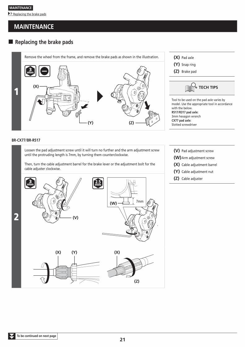
� Replacing the brake pads
1
Remove the wheel from the frame, and remove the brake pads as shown in the illustration. (X) Pad axle
(Y) Snap ring
(Z) Brake pad
TECH TIPS
Tool to be used on the pad axle varies by model. Use the appropriate tool in accordance with the below.R517/R317 pad axle: 3mm hexagon wrench CX77 pad axle: Slotted screwdriver(Z)(Y)
(X)
BR-CX77/BR-R517
2
Loosen the pad adjustment screw until it will turn no further and the arm adjustment screw until the protruding length is 7mm, by turning them counterclockwise.
Then, turn the cable adjustment barrel for the brake lever or the adjustment bolt for the cable adjuster clockwise.
(V) Pad adjustment screw
(W) Arm adjustment screw
(X) Cable adjustment barrel
(Y) Cable adjustment nut
(Z) Cable adjuster
(V)
(W) 7mm
(Y)(X)
(Z)
(X)
22To be continued on next page
MAINTENANCE
Replacing the brake pads
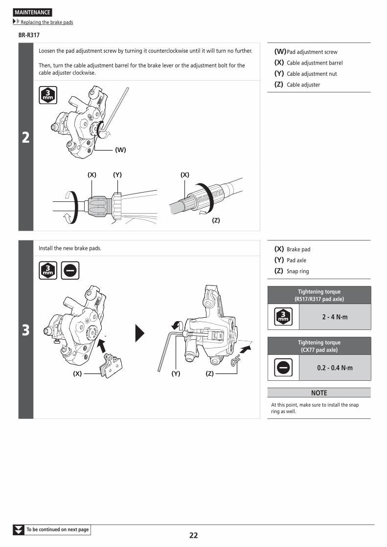
BR-R317
2
Loosen the pad adjustment screw by turning it counterclockwise until it will turn no further.
Then, turn the cable adjustment barrel for the brake lever or the adjustment bolt for the cable adjuster clockwise.
(W) Pad adjustment screw
(X) Cable adjustment barrel
(Y) Cable adjustment nut
(Z) Cable adjuster
(W)
(Y)(X)
(Z)
(X)
3
Install the new brake pads. (X) Brake pad
(Y) Pad axle
(Z) Snap ring
Tightening torque (R517/R317 pad axle)
2 - 4 N·m
Tightening torque (CX77 pad axle)
0.2 - 0.4 N·m
NOTE
At this point, make sure to install the snap ring as well.
(X) (Z)(Y)
23
MAINTENANCE
Replacing the brake pads
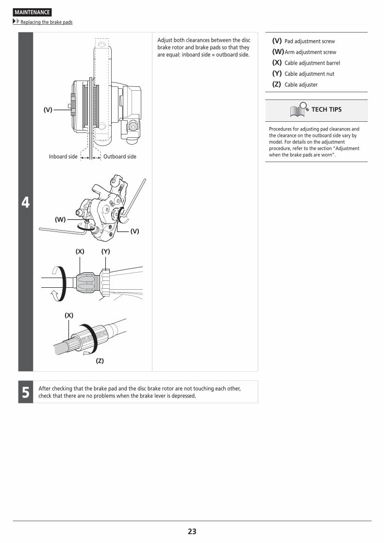
4
(Y)(X)
(W)
(V)
(Z)
(X)
(V)
Inboard side Outboard side
Adjust both clearances between the disc brake rotor and brake pads so that they are equal: inboard side = outboard side.
(V) Pad adjustment screw
(W) Arm adjustment screw
(X) Cable adjustment barrel
(Y) Cable adjustment nut
(Z) Cable adjuster
TECH TIPS
Procedures for adjusting pad clearances and the clearance on the outboard side vary by model. For details on the adjustment procedure, refer to the section “Adjustment when the brake pads are worn”.
5 After checking that the brake pad and the disc brake rotor are not touching each other, check that there are no problems when the brake lever is depressed.

Please note: specifications are subject to change for improvement without notice. (English) © Jan. 2017 by Shimano Inc. HTR