Embed Size (px)
Citation preview
Mechanical Characterization of
Talc Particle Filled Thermoplastics
Frank Kunkel1,∗, Florian Becker1, Stefan Kolling1,2
1 German Institute for Polymers (DKI), Department of Mechanics and SimulationSchlossgartenstr. 6, D-64289 Darmstadt, Germany
∗ corresponding author, e-mail: [email protected]
1,2 Institute of Mechanics and Materials, THM, Wiesenstr. 14, D-35390 Giessen, Germany
Summary:
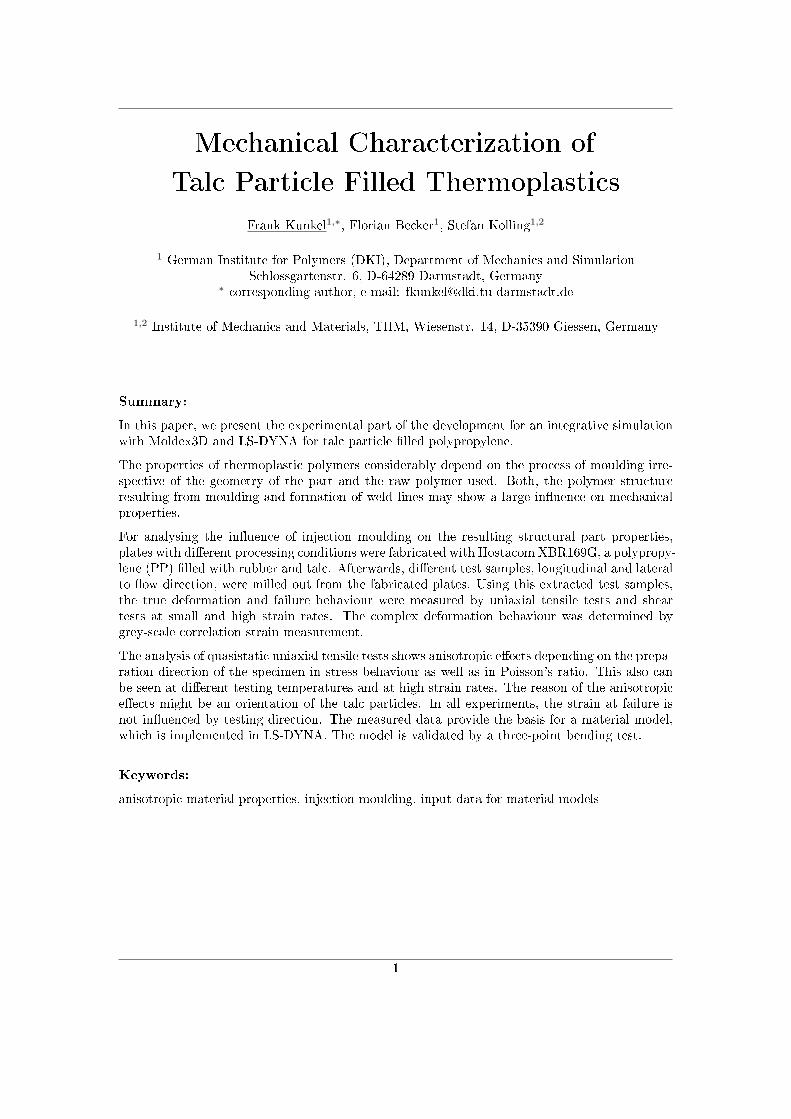
In this paper, we present the experimental part of the development for an integrative simulationwith Moldex3D and LS-DYNA for talc particle �lled polypropylene.
The properties of thermoplastic polymers considerably depend on the process of moulding irre-spective of the geometry of the part and the raw polymer used. Both, the polymer structureresulting from moulding and formation of weld lines may show a large in�uence on mechanicalproperties.
For analysing the in�uence of injection moulding on the resulting structural part properties,plates with di�erent processing conditions were fabricated with Hostacom XBR169G, a polypropy-lene (PP) �lled with rubber and talc. Afterwards, di�erent test samples, longitudinal and lateralto �ow direction, were milled out from the fabricated plates. Using this extracted test samples,the true deformation and failure behaviour were measured by uniaxial tensile tests and sheartests at small and high strain rates. The complex deformation behaviour was determined bygrey-scale correlation strain measurement.
The analysis of quasistatic uniaxial tensile tests shows anisotropic e�ects depending on the prepa-ration direction of the specimen in stress behaviour as well as in Poisson's ratio. This also canbe seen at di�erent testing temperatures and at high strain rates. The reason of the anisotropice�ects might be an orientation of the talc particles. In all experiments, the strain at failure isnot in�uenced by testing direction. The measured data provide the basis for a material model,which is implemented in LS-DYNA. The model is validated by a three-point bending test.
Keywords:
anisotropic material properties, injection moulding, input data for material models
1

1 Introduction
1 Introduction
The application of plastic materials in technical �elds is becoming more and more important.Therefore modelling and numerical simulations, in particular for safety-related components, be-come highly relevant. Actually car door panels made of PP are considered in the dimensioningof a car, to ful�l the requirements of the Euro NCAP crash test.
The deformation and failure behaviour of polymers is a�ected by its structure of long-chain,entangled or networked macromolecules [1, 2, 3]. In typical production processes as injectionmoulding, the microstructure of a plastic material is subjected to major changes. Mechanicalproperties like yield stress and strain at failure of the same polymer can �uctuate considerablydepending on the production history. This is also well known for �bre reinforced polymers, where,amongst others, the fountain �ow during �lling causes an orientation of the �bres. Nearby, asurface layer and an intermediate layer is generated [4, 5]. The �bres in the surface layer areoriented parallel, whereas the �bres in the intermediate layer are orientated perpendicular to�ow direction. This leads to an anisotropic deformation behaviour [6, 7].
Furthermore, the �ow of polymer melts in the �lling process can cause an orientation and astretching of the macromolecules and may change the phase morphology. In recent years, �llerslike talc or rubber are used in parts made from polypropylene. In contrast to �bre reinforcedpolymers the talc or rubber �lled polymers are naturally counted like the un�lled polymers to theclass of isotropic materials. But recent investigations show at least some anisotropic orientationof talc �lled polypropylene [8].
For an accurate �nite element modelling, the knowledge of the anisotropic deformation behaviourof �lled polypropylenes is therefore important. Without these considerations uncertainties areinvolved and it's necessary to make high factors of safety in a constructional element. For a bettermaterial utilization and a reliable design of components, it is therefore of great importance toimplicate the impact of process conditions taking e�ect on the material at a certain position of apart, to understand its mechanical properties and incorporated those in the material description.
Finally, the aim of the presented work is the development of an integrative simulation, see[9, 10]. Injection moulding simulation can calculate the local orientation of talc particles in thesample. This could be transferred to the �nite element analysis to a�ect the inhomogeneitieslike anisotropy in the simulation. The experiments shown in this paper are the necessary partto calibrate the �nite element simulation in order to develop an accurate integrative simulationfor the �eld of polypropylenes �lled with rubber and talc.
2 Experimental Methodolgy
In the following section, the preparation of the samples and the following mechanical tests liketensile or shear tests are described in detail.
2.1 Preparation of the Sample
First, plates made of Hostacom XBR169G (producer: LyondellBasell), a polypropylene �lled withtalc and rubber, were produced on the injection moulding machine FX-75 (producer: Klöckner-Desma Ferromatik). The size of the plates was 80mm x 80mm x 2, 5mm (see �gure 1), thetriangular gate ensures a parallel �ow front in the plate. The process parameters of injectionmoulding are shown in table 1.
2

2 Experimental Methodolgy
Figure 1: Injection moulded plate with delta gate
2.2 Sample Geometry
Proper material data from tensile, shear and bending tests are important to consider the defor-mation behaviour of �lled polypropylene as precisely as possible in the FE analysis. Therefore,prior to the tests the focus was set on the selection of suitable samples that could be milled ofthe prepared plates.
The selection of the sample's geometry for tensile tests is described in detail in [11] and [12].The development of the tensile bar and the geometry for shear test can be found the work ofBecker [13]. Becker's tensile bar for tensile tests and the z-sample for shear tests are usedboth for quasi-static and dynamic tests. The three-point bending tests are carried out on bars,where the width remains constant over bar length, i. e. not tailed. All three geometries canbe easily milled out of the injection moulded plates. The exact geometry of the samples shows�gure 2: on the left hand side, the geometry for tensile tests is shown. In the middle, the sheargeometry can be found, whereas the right image shows the geometry of the bending samples.
To determine the e�ect of anisotropy of the sample on the deformation behaviour, the test
Table 1: Process parameters of Hostacom XBR169G
melt temperature [◦C] 240mould temperature [◦C] 40
injection time [s] 4holding pressure [MPa] 40holding time [s] 30cooling time [s] 20
3

2 Experimental Methodolgy
Figure 2: Di�erent sample geometries
specimens are taken longitudinal and lateral to �ow direction. The scheme of the withdrawalposition is shown in �gure 3. Analogous to the tensile specimens, shear and bending samples aremilled out at the same positions.
2.3 Mechanical Characterization
In the analysis of the crash behaviour of plastic materials, high strain rates should be realized inthe testing region. Neglecting the e�ects described above, the resulting strain rate depends onthe haul-o� speed and the geometry of the test specimen. Both parameters can not be changedarbitrarily. Machines and measurement technology restrict the haul-o� speed and the geometryof the specimen, which also limits the theoretically achievable strain rate.
The tests at constant or variable strain rate are executed with a high speed servo-hydraulictesting machine [14]. Using proper test specimens and testing devices, di�erent stress states canbe achieved. The dynamic uniaxial tensile tests were performed using the servohydraulic testingmachine HTM5020 from Zwick (max. 20m/s, 50 kN) at T = 23 ◦C. The quasi-static tesile,shear and bending tests were performed on the Zwick universal testing machine Z020 (max.
Figure 3: Withdrawal positions of samples
4

2 Experimental Methodolgy
Figure 4: Tensile bar with grey scale pattern
750mm/min, 20 kN) at T = −35 ◦C, T = 23 ◦C and T = 80 ◦C. Three retries per test serieswere performed.
2.4 Strain Measurement
E�ects, such as the necking of the tensile bar in the plastic region can lead to high local di�erencesin the deformation of the sample. Therefore, a local strain measurement is required. The strainmeasurement via the crosshead displacement is not appropriate, since in this method an averagestrain value over the entire sample length is determined and local e�ects are neglected.
One method to measure the strain throughout the entire test locally is the grey-scale correlation[3, 14]. Thereby a stochastic grey-scale pattern is applied to the sample (see �gure 4) and �lmedwith a digital camera during the test. After the test, displacements and distortions of the patternbased on the stored images are calculated using a cross correlation algorithm [15].
From the calculated displacements of the sample surface between two images, the strain on theentire surface can be calculated. After the image correlation, the local displacement and straindistribution on the sample surface for each captured image is available, as shown in �gure 5.
Hence, local strains that occur during the test can be determined. The two-dimensional straininformation can be converted by averaging a section in a scalar strain value for each time step.The length of the averaged section can be chosen either absolute (e. g. 5mm) or relative (e. g.95% of the maximum strain.) In the results shown later, a strain section of 2mm and themaximum strain in direction of loading were selected.
For the dynamic tests, the force signal is �ltered, since the impact load created during the test bythe design of the testing machine and the position of the load cell generates strong oscillations inthe system. A detailed description of the �ltering methods can be found in the work of Becker[13].
Figure 5: Correlated single picture including facets [13]
5

3 Test Results
3 Test Results
In the following chapter the experimental results are presented. The in�uence of test temperature,strain rate and stress state to the deformation behaviour is displayed. The measured materialdata are the basis for a material model for crash simulations, which were presented by Hempeland Seelig in [16]. The validation of the model is performed via bending tests.
3.1 In�uence of the Extraction Direction of the Sample
First, the dependence of test direction on the deformation behaviour of Hostacom XBR169Gis shown. Figure 6 shows for both testing directions, longitudinal and lateral to �ow direction,a small tendency for strain hardening of Hostacom XBR169G. In addition the material showsdi�erence in the stress level of 20% between samples taken longitudinal and lateral to �owdirection. The di�erences in Poisson's ratio between these samples are at more than 60% (see�gure 7). Interesting in the results is the fact that the considered class of materials (polypropylene�lled with talcum and rubber) usually is counted to the group of isotropic materials. In thesimulation, therefore, usually no directional parameters have been taken into consideration.
Figure 6: Stress-strain-behaviour of Hostacom XBR169G
The di�erent degree of anisotropy in di�erent polymers, can have several reasons. An orientationof the talc particles could occur in Hostacom XBR169G, which align themselves along a preferreddirection in the �lling process during injection moulding. This would result in a reinforcing e�ect,if the loading direction coincides to this preferred direction. Similarly an alignment of the EPDMwould be possible; the rubber spheres could deform during the �lling process by the high shearforces and also align along a preferred direction. To clarify this issue, images with a scanningelectron microscope were made. In �gure 8 the fracture surface of a tensile bar made of HostacomXBR169G is shown, which was produced by cold shortness. As expected, a preferred orientationof the talc particles can be observed in the �ow direction. Similar results are shown by Zhouand Mallick [17]: they present anisotropic e�ects which are created by injection moulding.The injection moulding process in�uences skin-core morphology exhibiting di�erent orientationof talc particles in the skins than in the core.
6

3 Test Results
Figure 7: Poisson's ratio of Hostacom XBR169G
Besides the tensile tests also shear tests were performed. Figure 9 shows the shear stress asa function of shear strain for samples taken longitudinal and lateral to �ow direction. Undershear load the talc and and rubber �lled polypropylene shows no anisotropic e�ects. There is nodi�erence in the shear stress level recognizable. It should be noted, that the end of the curvesdoes not indicate the failure in shear. At this point, the distortions are too high. The evaluationof grey-scale correlation can not be made appropriate. Furthermore, at large deformations it isnot a simple shear state any more.
3.2 In�uence of Testing Temperature
Another important e�ect on the deformation and failure behaviour is the test temperature. Thesein�uences must also be properly considered in a material model. Relevant temperatures for theautomotive sector are −35 ◦C < T < +80 ◦C. Therefore, quasi-static tensile tests were performedat the test temperatures T = −35 ◦C, T = 23 ◦C and T = 80 ◦C. The deformation behaviour of
Figure 8: SEM pictures with magni�cation 1500 (left) and 5000 (right)
7

3 Test Results
Figure 9: Shear behaviour of Hostacom XBR169G
Hostacom XBR169G is shown in �gure 10.
For all temperatures, a signi�cantly higher stress level occurs in samples taken longitudinal tothe �ow direction. The di�erences measured between T = −35 ◦C and T = 23 ◦C are at about20%, whereas the di�erence at T = 80◦C turns out lower, but the di�erences in stress levelincrease with ongoing strain.
3.3 In�uence of Strain Rate
For a complete material data set, apart from the temperature dependency, the in�uence ofthe strain rate on the deformation behaviour plays also an important role. This is illustrated in
Figure 10: In�uence of testing temperature of Hostacom XBR169G
8

3 Test Results
Figure 11: Strain rate dependence of Hostacom XBR169G
�gure 11 for Hostacom XBR169G for samples which were taken longitudinal to the �ow direction.In the top chart the true stress, in the lower graph the strain rate is shown as a function of thetrue strain. Therein, a signi�cant strain rate hardening is recognizable. Strain hardening existshowever only in the quasi-static test. The diagram of strain rate over the strain shows, that thestrain rates developing at a constant haul-o� speed of the testing machine are not constant withstrain.
To demonstrate the distinctive anisotropic e�ects, the values strain rate and yield stress arecharted from �gure 11. Thereby, the withdrawal direction of the tensile specimens, longitudinaland lateral to �ow direction, is considered. The measured data shows �gure 12. In the doublelogarithmic plot yield stress (maximum stress before necking) and strain rate show a linearcorrelation. This relationship depends on the extraction direction of the tensile specimens. Thesamples taken longitudinal to the �ow direction always show a higher yield stress than the lateraltaken tensile specimens; the average di�erence is about 15%.
9

4 Validation via Three Point Bending Test
Figure 12: Anisotropic and strain rate dependent yield stress of Hostacom XBR169G
3.4 Summary of Mechanical Characterization
Hostacom XBR169G, generally counting as isotropic material, showed an interesting and complexdeformation behaviour in the mechanical characterization. Therefore tensile- and shear tests werecarried out at various test temperatures and test speeds. It appeared
• no distinct strain hardening for higher strain rates,
• a pronounced strain rate hardening,
• anisotropic e�ects in stress level according to testing direction in tensile tests,
• no anisotropy in shear tests,
• a resultant anisotropic and strain rate dependent yield stress,
• an anisotropic lateral strain behaviour
• and an increase of volume with increasing true strain.
These characteristics of Hostacom XBR169G have been considered in a material model that wasdeveloped by Hempel and Seelig. Details of the material model can be found in [16] and arenot explained explicitly here.
4 Validation via Three Point Bending Test
After developing the material model in [16] �nally the validation of three-point bending testsshould be described brie�y. The bending tests were performed with the samples of �gure 2.Figure 13 shows the experimental setup for bending tests.
The bending tests were performed at constant test speed of 2mm/min. The experimental setupbases on DIN EN ISO 178 [18]. Figure 14 shows the behaviour of Hostacom XBR169G at thebending test. Just like the tensile tests the force displacement diagram shows anisotropic e�ectsof approximately 20%.
10

4 Validation via Three Point Bending Test
Figure 13: Eperimental setup of bending tests
In return the three-point bending test was simulated in LS-Dyna with the developed materialmodel. The shell model contains of 3.200 elements and 10 integration points in the directionof thickness. Figure 15 shows the di�erences between measured and simulated behaviour of theforce displacement diagram for the bending tests for longitudinal and lateral samples. The graphsshow a good conformity with di�erences of only 10%. Consequently the developed material modeldescribes the deformation behaviour of Hostacom XBR169G in the three-point bending test verywell. The description of the uniaxial tensile test for di�erent (quasistatic and dynamic) strainrates �ts also very well. This is shown by Hempel and Seelig in [16]. The material model willprobably be implemented in LS-Dyna in 2011.
Figure 14: Three point bending test results of Hostacom XBR169G
11

5 Summary and Outlook
Figure 15: Validation of the material model of Hostacom XBR169G
5 Summary and Outlook
The aim of this study is to create a solid experimental basis for a material model for crashsimulation, taking into account an anisotropy induced by injection moulding. The researchesshows that this anisotropy in Hostacom XBR169G, a PP �lled with talc and EPDM, showspronounced di�erences in stress levels both at high strain rates and at di�erent test temperatures.These di�erences for tensile bars, which are taken longitudinal and lateral to the �ow directionof injection moulded plates, do not occur in shear tests.
The measured stress-strain curves in combination with the measurement of strain dependinglateral extension at di�erent strain rates and test temperatures are used by Hempel and Seelig[16] as a basis to create a material model for Hostacom XBR169G and its application in crashsimulation. This material model was validated successfully in LS-Dyna via three point bendingtests an will be implemented in LS Dyna in the future.
Furthermore, the prepared samples will be analysed using SEM and TEM to explain the oc-
12

6 Acknowledgement
currence of anisotropy depending on injection moulding settings. Approaches for an alignmentof the talc particles have already been explained in literature. Furthermore, the in�uence ofinjection moulding setting is analysed in more detail using other plates produced under di�erentinjection moulding settings. Through these researches it will be possible to explain the measuredstress di�erences depending on orientation.
6 Acknowledgement
This research project of the IGF named 15826N of the research association ForschungsgesellschaftKunststo�e e. V., Schlossgartenstraÿe 6, 64289 Darmstadt dealing with �Verbesserung der Crash-simulation von Kunststo�bauteilen durch Einbinden der Morphologiedaten aus der Spritzgieÿsim-ulation� was supported by the AiF.
This was possible within the framework of the programme to expedite the industrial collectiveresearch and development (IGF) of the Federal Ministry for Economic A�airs and Technologyby a decision of the German Parliament. We would like to thank them for this sponsorship.
The work was carried out in co-operation with �Forschungsvereinigung Automobiltechnik e.V.(FAT)�. We also would like to thank them for fruitful discussions.
Literature
[1] Retting, W.: Mechanik der Kunststo�e. München, ISBN 3446161015, Hanser, 1991
[2] Strobl, G.R.: The Physics of Polymers: Concepts for Understanding Their Structures andBehavior. 2nd edition, Berlin, ISBN 3540632034, Springer, 1997
[3] Huberth, F.; Rohr, I.; Hiermaier, S.: Deformationsverhalten thermoplastischer Polymere.In S. Kolling (Hrsg.): Beiträge zur Experimentalphysik, Didaktik und computergestütztenPhysik. Logos Verlag, Berlin, S.195-215, 2007
[4] Hauck, C.; Brouwers, G.: Faserverstärkte Spritzguss-Bauteile optimal auslegen: Neues Werk-sto�gesetz ermöglicht Berücksichtigung der Faserorientierung. In: Kunststo�e 82 (7): 586-590, 1992
[5] Bay, R.S.; Tucker III, C.L.: Fiber orientation in simple injection moldings. Part II: Experi-mental results. In: Polymer Composites 13 (4): 332-341, 1992
[6] Ericson, M.; Berglund, L.: Deformation and fracture of glass-mat-reinforced polypropylene.In: Composites science and technology 43 (3): 269-281, 1992
[7] Mallick, P.K.: Fiber-reinforced composites: materials, manufacturing, and design. ISBN0849342058, CRC-Press, 2007
[8] Choi, W.J.; Kim, S.C.: E�ects of talc orientation and non-isothermal crystallization rate oncrystal orientation of polypropylene in injection-molded polypropylene/ethylene-propylenerubber/talc blends. In: Polymer 45, 2393 - 2401, 2004
[9] Glaser, S.; Wüst, A.; Frik, S.; Erzgraber, M.: Integrative Simulation fur crashbelasteteBauteile aus faserverstarkten thermoplastischen Polymeren. In: VDI-Berichte 1967 (1): 343,2006
13

Literature
[10] Glaser, S.; Wüst, A.: Crash Simulation of Composite Structures - The importance of processinduced material data. In: Proceedings of the 4th LS-Dyna Forum, Bamberg, Germany, 2005
[11] Kunkel, F.; Becker, F.: Talcum Particle Reinforced Thermoplastics Part I: In�uences ofProcessing Conditions and Experimental Characterization. In: Proceedings of the 9th LS-Dyna Forum, Bamberg, Germany, F-II-1, 2010
[12] Kunkel, F.; Becker, F.: From Granules to FEM: Polymers in Numerical Simulation. In:Ansys-Conference & 28. CADFEM Users' Meeting 04.11.2010, Aachen, ISBN: 3-9809901-7-6
[13] Becker, F.: Entwicklung einer Beschreibungsmethodik für das mechanische Verhalten un-verstärkter Thermoplaste bei hohen Deformationsgeschwindigkeiten. Halle, Univ., Zentrumfür Ingenieurwissenschaften, Diss., 2009
[14] Hobeika, S.: Lokales Deformationsverhalten bei hohen Geschwindigkeiten: Polymer-physik für die Crash-Simulation. Fachtagung Kunststo�e+Simulation 13.-14. Juni 2007, Fell-bach/Stuttgart
[15] Keane, R.D.; Adrian, R.J.: Theory of Cross-Correlation Analysis of PIV Images. In: AppliedScienti�c Research 49 (3): 191-215, 1992
[16] Hempel, P.; Seelig, T.: Talcum Particle Reinforced Thermoplastics - Part II: Material Mod-eling and Simulation. Proceedings of the 9th German LS-DYNA Forum, Bamberg, 2010
[17] Zhou, Y.; Mallick, P.: E�ects of Melt Temperature and Hold Pressure on the Tensile and Fa-tigue Properties of an Injection Moulded Talc-Filled Polypropylene. In: Polymer Engineering& Science 45 (6): 755-763, 2005
[18] DIN EN ISO 178: 2006-04 Kunststo�e - Bestimmung der Biegeeigenschaften (ISO 178:2001+ AMD 1:2004); Deutsche Fassung EN ISO 178:2003 + A1:2005
14