Embed Size (px)
Citation preview

MECHANICAL

ME(H4DOTC)-2
General DescriptionMECHANICAL
1. General DescriptionA: SPECIFICATION
Engine
Model 2.5 L
Cylinder arrangementHorizontally opposed, liquid cooled, 4-cylinder, 4-stroke gasoline engine
Valve system mechanismBelt driven, double overhead camshaft,
4-valve/cylinder
Bore × Stroke mm (in) 99.5 × 79.0 (3.92 × 3.11)
Piston displacement cm3 (cu in) 2,457 (149.94)
Compression ratio 8.4
Compression pressure (at 200 — 300 rpm)
kPa (kg/cm2, psi) 981 — 1,177 (10 — 12, 142 — 171)
Number of piston rings Pressure ring: 2, Oil ring: 1
Intake valve timing
OpenMax. retard ATDC 5°
Min. advance BTDC 35°
CloseMax. retard ABDC 65°
Min. advance ABDC 25°
Exhaust valve timingOpen BBDC 55°
Close ATDC 5°
Valve clearance mm (in)
Inspection value
Intake 0.20+0.04–0.06 (0.0079+0.0016
–0.0024)
Exhaust 0.35±0.05 (0.0138±0.0020)
Adjustment value
Intake 0.20+0.01–0.03 (0.0079+0.0004
–0.0012)
Exhaust 0.35±0.02 (0.0138±0.0008)
Idling speed [at neutral position on MT, or “P” or “N” position on AT]
rpmNo load 750±100
A/C ON800±100 (MT model)825±100 (AT model)
Ignition order 1 → 3 → 2 → 4
Ignition timing BTDC/rpmMT model 12°±10°/750
AT model 17°±10°/750

ME(H4DOTC)-3
General DescriptionMECHANICAL
NOTE:OS: Oversize US: Undersize
Belt tension adjuster
Protrusion of adjuster rod mm (in) 5.2 — 6.2 (0.205 — 0.244)
Belt tensioner
Spacer O.D. mm (in) 17.955 — 17.975 (0.7069 — 0.7077)
Tensioner bushing I.D. mm (in) 18.0 — 18.08 (0.7087 — 0.7118)
Clearance between spacer and bushing
mm (in) Standard 0.025 — 0.125 (0.0010 — 0.0049)
Side clearance of spacer mm (in) Standard 0.20 — 0.55 (0.0079 — 0.0217)
Camshaft
Bending limit mm (in) 0.020 (0.0079) or less
Thrust clearance mm (in) Standard 0.068 — 0.116 (0.0027 — 0.0047)
Cam lobe height mm (in)Intake Standard 46.55 — 46.65 (1.833 — 1.837)
Exhaust Standard 46.75 — 46.85 (1.841 — 1.844)
Journal O.D. mm (in) StandardFront 37.946 — 37.963 (1.4939 — 1.4946)
Center rear 29.946 — 29.963 (1.1790 — 1.1796)
Journal clearance mm (in) Standard 0.037 — 0.072 (0.0015 — 0.0028)
Cylinder head
Surface warpage limit mm (in) 0.035 (0.0014)
Grinding limit mm (in) 0.3 (0.012)
Standard height mm (in) 127.5 (5.02)
Valve seat
Seating angle 90°
Contacting width mm (in)Intake Standard 0.6 — 1.4 (0.024 — 0.055)
Exhaust Standard 1.2 — 1.8 (0.047 — 0.071)
Valve guideInside diameter mm (in) 6.000 — 6.012 (0.2362 — 0.2367)
Protrusion above head mm (in) 15.8 — 16.2 (0.622 — 0.638)
Valve
Head edge thickness mm (in)Intake Standard 1.0 — 1.4 (0.039 — 0.055)
Exhaust Standard 1.3 — 1.7 (0.051 — 0.067)
Stem outer diameter mm (in)Intake 5.955 — 5.970 (0.2344 — 0.2350)
Exhaust 5.945 — 5.960 (0.2341 — 0.2346)
Valve stem gap mm (in) StandardIntake 0.030 — 0.057 (0.0012 — 0.0022)
Exhaust 0.040 — 0.067 (0.0016 — 0.0026)
Overall length mm (in)Intake 104.4 (4.110)
Exhaust 104.65 (4.1201)
Valve spring
Free length mm (in) 47.32 (1.863)
Squareness 2.5°, 2.1 mm (0.083 in) or less
Tension/spring height N (kgf, lb)/mm (in)Set
205 — 235(20.9 — 24.0, 46.1 — 52.8)/36.0 (1.417)
Lift426 — 490
(43.4 — 50.0, 95.8 — 110)/26.5 (1.043)
Valve lifter
Outer diameter mm (in) Standard 34.959 — 34.975 (1.3763 — 1.3770)
Inner diameter (cylinder head) mm (in) Standard 34.994 — 35.016 (1.3777 — 1.3786)
Valve lifter clearance mm (in) Standard 0.019 — 0.057 (0.0007 — 0.0022)
Cylinder block
Surface warpage limit(Mating surface with cylinder head)
mm (in) 0.025 (0.0098)
Grinding limit mm (in) 0.1 (0.004)
Standard height mm (in) 201.0 (7.91)
Cylinder inner diameter mm (in) StandardA 99.505 — 99.515 (3.9175 — 3.9179)
B 99.495 — 99.505 (3.9171 — 3.9175)
Taper mm (in) Standard 0.015 (0.0006)
Out-of-roundness mm (in) Standard 0.010 (0.0004)
Piston clearance mm (in) Standard –0.010 — 0.010 (–0.00039 — 0.00039)
Cylinder inner diameter boring limit (diameter) mm (in) To 100.005 (3.9372)

ME(H4DOTC)-4
General DescriptionMECHANICAL
Piston Outer diameter mm (in)
StandardA 99.505 — 99.515 (3.9175 — 3.9179)
B 99.495 — 99.505 (3.9171 — 3.9175)
0.25 (0.0098) OS 99.745 — 99.765 (3.9270 — 3.9278)
0.50 (0.0197) OS 99.995 — 100.015 (3.9368 — 3.9376)
Piston pin
Standard clearance between piston and piston pin
mm (in) Standard 0.004 — 0.008 (0.0002 — 0.0003)
Degree of fitPiston pin must be fitted into position with
thumb at 20°C (68°F).
Piston ring
Ring closed gap mm (in)
Top ring Standard 0.20 — 0.25 (0.0079 — 0.0098)
Second ring Standard 0.37 — 0.52 (0.015 — 0.0203)
Oil ring Standard 0.20 — 0.50 (0.0079 — 0.0197)
Ring groove gap mm (in)Top ring Standard 0.040 — 0.080 (0.0016 — 0.0031)
Second ring Standard 0.030 — 0.070 (0.0012 — 0.0028)
Connecting rodBend or twist per 100 mm (3.94 in) in length
mm (in) Limit 0.1 (0.0039)
Thrust clearance mm (in) Standard 0.070 — 0.330 (0.0028 — 0.0130)
Bearing of large end
Oil clearance mm (in) Standard 0.017 — 0.045 (0.0007 — 0.0018)
Bearing size(Thickness at center)
mm (in)
Standard 1.490 — 1.502 (0.0587 — 0.0591)
0.03 (0.0012) US 1.504 — 1.512 (0.0592 — 0.0595)
0.05 (0.0020) US 1.514 — 1.522 (0.0596 — 0.0599)
0.25 (0.0098) US 1.614 — 1.622 (0.0635 — 0.0639)
Bushing of small end
Clearance between piston pin and bushing
mm (in) Standard 0 — 0.022 (0 — 0.0009)
Crankshaft
Bending limit mm (in) 0.035 (0.0014)
Crank pin
Out-of-roundness mm (in) 0.003 (0.0001)
Cylindricality mm (in) 0.004 (0.0002)
Grinding limit (dia.) mm (in) To 51.750 (2.0374)
Crank journal
Out-of-roundness mm (in) 0.005 (0.0002)
Cylindricality mm (in) 0.006 (0.0002)
Grinding limit (dia.) mm (in) To 59.758 (2.3527)
Crank pin outer diameter mm (in)
Standard 51.984 — 52.000 (2.0466 — 2.0472)
0.03 (0.0012) US 51.954 — 51.970 (2.0454 — 2.0461)
0.05 (0.0020) US 51.934 — 51.950 (2.0447 — 2.0453)
0.25 (0.0098) US 51.734 — 51.750 (2.0368 — 2.0374)
Crank journal outer diameter
mm (in)
Standard 59.992 — 60.008 (2.3619 — 2.3625)
0.03 (0.0012) US 59.962 — 59.978 (2.3607 — 2.3613)
0.05 (0.0020) US 59.942 — 59.958 (2.3599 — 2.3605)
0.25 (0.0098) US 59.742 — 59.758 (2.3520 — 2.3527)
Thrust clearance mm (in) Standard 0.030 — 0.115 (0.0012 — 0.0045)
Oil clearance mm (in) 0.010 — 0.030 (0.0004 — 0.0012)
Main bearingBearing size (Thickness at center)mm (in)
#1, #3
Standard 1.998 — 2.011 (0.0787 — 0.0792)
0.03 (0.0012) US 2.017 — 2.020 (0.0794 — 0.0795)
0.05 (0.0020) US 2.027 — 2.030 (0.0798 — 0.0799)
0.25 (0.0098) US 2.127 — 2.130 (0.0837 — 0.0839)
#2, #4, #5
Standard 2.000 — 2.013 (0.0787 — 0.0793)
0.03 (0.0012) US 2.019 — 2.022 (0.0795 — 0.0796)
0.05 (0.0020) US 2.029 — 2.032 (0.0799 — 0.0800)
0.25 (0.0098) US 2.129 — 2.132 (0.0838 — 0.0839)

ME(H4DOTC)-5
General DescriptionMECHANICAL
B: COMPONENT1. TIMING BELT
(1) Timing belt cover No. 2 RH (12) Timing belt Tightening torque:N·m (kgf-m, ft-lb)
(2) Timing belt guide (MT model) (13) Belt idler No. 2 T1: 5 (0.5, 3.7)
(3) Crank sprocket (14) Belt idler T2: 9.75 (1.0, 7.2)
(4) Timing belt cover No. 2 LH (15) Timing belt cover LH T3: 24.5 (2.5, 18.1)
(5) Tensioner bracket (16) Front belt cover T4: 39 (4.0, 28.8)
(6) Automatic belt tension adjuster ASSY
(17) Timing belt cover RH T5: <Ref. to ME(H4DOTC)-60, INSTALLATION, Cam Sprocket.>
(18) Crank pulley (MT model)
(7) Belt idler (19) Timing belt guide (MT model)
(8) Exhaust cam sprocket RH (20) O-ring T6: <Ref. to ME(H4DOTC)-48, INSTALLATION, Crank Pulley.>(9) Intake cam sprocket RH (21) Actuator cover
(10) Intake cam sprocket LH (22) Crank pulley (AT model) T7: 6.4 (0.65, 4.7)
(11) Exhaust cam sprocket LH T8: 3.4 (0.3, 2.5)
T9: 25 (2.5, 18.4)
ME-03553
T5
T1
(7)
(6)
(10)
(5)
(14)
(2)
(3)T2
(4)
(1)(19)
(19)
T7
T4
T3
T9
T4
T5
T4
T5 T1
T7
(11)
(15)
(17)
(19)
(9)
(8)
(13)
(14)
(12)
(16)
T1
T1
T7
T1
T1
T5
(20)
(20)
T1
T8
T8
T1
(21)
(21)
T6(18)
(22) T1

ME(H4DOTC)-6
General DescriptionMECHANICAL
2. CYLINDER HEAD AND CAMSHAFT
ME-03090
T7 (1)
T3
T3
T5
T5
T5
T5
T1
(3)
(7)
(6)
(9)(8)
(10)
(12)
(28)
(31)
(13)
(25)(21)
(20)
(6)
(16)
(17)
(18)
(9)(8)
(19)
(15)
(14)
(29)(11)
(5)
(4)
(22)T7
T7
(14)
(29)
(12)
(27)
(27)
(26)(27)
(31)
(30)
T2
T2
T2
T6
T1(11)
(2)
T6
T2
T2
T6
(30)
T6
(24)
(23)
T4
(32)

ME(H4DOTC)-7
General DescriptionMECHANICAL
(1) Rocker cover RH (18) Front camshaft cap LH Tightening torque:N·m (kgf-m, ft-lb)
(2) Rocker cover gasket RH (19) Intake camshaft cap LH T1: <Ref. to ME(H4DOTC)-70, INSTALLATION, Cylinder Head.>
(3) Front camshaft cap RH (20) Exhaust camshaft cap LH
(4) Intake camshaft cap RH (21) Rocker cover gasket LH
(5) Intake camshaft RH (22) Rocker cover LH T2: 8 (0.8, 5.9)
(6) Oil flow control solenoid valve (23) Oil filler cap T3: <Ref. to ME(H4DOTC)-64, INSTALLATION, Camshaft.>(7) Exhaust rear camshaft cap RH (24) Oil filler duct
(8) Gasket (25) O-ring T4: 6.4 (0.65, 4.7)
(9) Oil return cover (26) Oil pipe LH T5: <Ref. to ME(H4DOTC)-64, INSTALLATION, Camshaft.>(10) Exhaust camshaft RH (27) Gasket
(11) Cylinder head bolt (28) Oil pipe RH T6: 29 (3.0, 21.4)
(12) Oil seal (29) Stud bolt T7: <Ref. to ME(H4DOTC)-64, INSTALLATION, Camshaft.>(13) Cylinder head RH (30) Union screw with filter
(with protrusion)(14) Cylinder head gasket
(15) Cylinder head LH (31) Union screw without filter (without protrusion)(16) Intake camshaft LH
(17) Exhaust camshaft LH (32) Gasket

ME(H4DOTC)-8
General DescriptionMECHANICAL
3. CYLINDER HEAD AND VALVE ASSEMBLY
(1) Exhaust valve (6) Valve spring (11) Intake valve guide
(2) Intake valve (7) Retainer (12) Exhaust valve guide
(3) Cylinder head (8) Retainer key (13) Plug
(4) Valve spring seat (9) Valve lifter
(5) Intake valve oil seal (10) Exhaust valve oil seal
ME-03157
(3)
(1)
(2)
(11) (4) (5) (6) (7) (8) (9)
(11)
(12)
(12)
(10)
(4)
(4)
(5) (6)
(6)
(7)
(7)
(8)
(8)
(9)
(9)(10)
(4)
(6)
(7)
(8)
(9)
(13)
(13)

ME(H4DOTC)-9
General DescriptionMECHANICAL
4. CYLINDER BLOCK
ME-03554
T7
T2
T2
T2
T5
T4
T5
T4
T2
T6
T6
T4
(9)
(6)
(10)
(10)(11)
(13)
(25)
(26)
(4)
(4)
(4)
(3)
(3)
(3)
(2)
(1)
(5)
(10)
T4
T6
T2
(24)
(17)
(27)T6
T2
(14)
(28)
T3
(18)
(10)
T2
(29)
T2
(23)
(31)
T1
T8
(19)
(20)
(21)(22)
T10
(32)
(10)
T2
(8)
(7)
(15)
(15)
T2
(30)(29)
(30)
(12)
(16)
T9

ME(H4DOTC)-10
General DescriptionMECHANICAL
(1) Oil pressure switch (17) Oil filter connector Tightening torque:N·m (kgf-m, ft-lb)
(2) Cylinder block RH (18) Oil strainer T1: 5 (0.5, 3.7)
(3) Service hole plug (19) Gasket T2: 6.4 (0.65, 4.7)
(4) Gasket (20) Oil pan T3: 10 (1.0, 7.2)
(5) Oil separator cover (21) Drain plug T4: 25 (2.5, 18.4)
(6) Water by-pass pipe (22) Drain plug gasket T5: <Ref. to ME(H4DOTC)-82, INSTALLATION, Cylinder Block.>
(7) Oil pump (23) Oil level gauge guide
(8) Front oil seal (24) Oil filter
(9) Rear oil seal (25) Gasket T6: 70 (7.1, 51.6)
(10) O-ring (26) Water pump hose T7: First 12 (1.2, 8.9)Second 12 (1.2, 8.9)(11) Service hole cover (27) Plug
(12) Cylinder block LH (28) Seal T8: 44 (4.5, 32.5)
(13) Water pump (29) Washer T9: 45 (4.6, 33.2)
(14) Baffle plate (30) Seal washer T10: 16 (1.6, 11.8)
(15) Oil pump seal (31) O-ring
(16) Water pump sealing (32) Engine rear hanger
ME(H4DOTC)-11
General DescriptionMECHANICAL
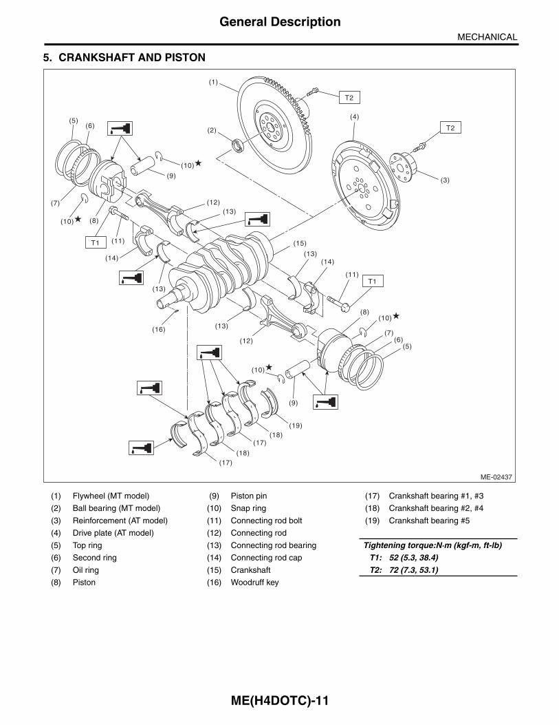
5. CRANKSHAFT AND PISTON
(1) Flywheel (MT model) (9) Piston pin (17) Crankshaft bearing #1, #3
(2) Ball bearing (MT model) (10) Snap ring (18) Crankshaft bearing #2, #4
(3) Reinforcement (AT model) (11) Connecting rod bolt (19) Crankshaft bearing #5
(4) Drive plate (AT model) (12) Connecting rod
(5) Top ring (13) Connecting rod bearing Tightening torque:N·m (kgf-m, ft-lb)
(6) Second ring (14) Connecting rod cap T1: 52 (5.3, 38.4)
(7) Oil ring (15) Crankshaft T2: 72 (7.3, 53.1)
(8) Piston (16) Woodruff key
ME-02437
T1
(5)(6)
(7)
(10) (8)
(10)
(12)(13)
(13)
(16) (13)
(12)
(19)(18)
(17)
(17)(18)
(10)
(10)
(7)(6)
(5)
(9)
(8)
(13)
(15)
(14)
(11)
(14)
(9)
T1 (11)
(1)
T2
(2)
(4)
(3)
T2

ME(H4DOTC)-12
General DescriptionMECHANICAL
6. ENGINE MOUNTING
(1) Front cushion rubber Tightening torque:N·m (kgf-m, ft-lb)
T1: 35 (3.6, 25.8)
T2: 85 (8.7, 62.7)
ME-03547
(1)
T2
T1
T1T2

ME(H4DOTC)-13
General DescriptionMECHANICAL
C: CAUTION• Wear appropriate work clothing, including a cap,protective goggles and protective shoes when per-forming any work.• Remove contamination including dirt and corro-sion before removal, installation or disassembly.• Keep the disassembled parts in order and pro-tect them from dust and dirt.• Before removal, installation or disassembly, besure to clarify the failure. Avoid unnecessary re-moval, installation, disassembly and replacement.• Vehicle components are extremely hot after driv-ing. Be wary of receiving burns from heated parts.• Be sure to tighten fasteners including bolts andnuts to the specified torque.• Place shop jacks or rigid racks at the specifiedpoints.• Before disconnecting connectors of sensors orunits, be sure to disconnect the ground cable fromthe battery.• All parts should be thoroughly cleaned, payingspecial attention to engine oil passages, pistonsand bearings.• Rotating parts and sliding parts such as piston,bearing and gear should be coated with oil prior toassembly.• Be careful not to let oil, grease or engine coolantcontact the timing belt, clutch disc and flywheel.• All removed parts, if to be reused, should be re-installed in the original positions and directions.• Bolts, nuts and washers should be replaced withnew parts as required.• Even if necessary inspections have been madein advance, proceed with assembly work whilemaking rechecks.• Remove or install the engine in an area wherechain hoists, lifting devices, etc. are available forready use.• Be sure not to damage coated surfaces of bodypanels with tools, or not to stain seats and windowswith coolant or oil. Place a cover over fender, as re-quired, for protection.• Prior to starting work, prepare the following:Service tools, clean cloth, containers to catch cool-ant and oil, wire ropes, chain hoist, transmissionjacks, etc.• Lift up or lower the vehicle when necessary.Make sure to support the correct positions.

ME(H4DOTC)-14
General DescriptionMECHANICAL
D: PREPARATION TOOL1. SPECIAL TOOL
ILLUSTRATION TOOL NUMBER DESCRIPTION REMARKS
498267600 CYLINDER HEAD TABLE
• Used for replacing valve guides.• Used for removing and installing valve spring.
498277200 STOPPER SET Used for installing automatic transmission assembly to engine.
498457000 ENGINE STAND ADAPTER RH
Used together with the ENGINE STAND (499817100).
498457100 ENGINE STAND ADAPTER LH
Used together with the ENGINE STAND (499817100).
ST-498267600
ST-498277200
ST-498457000
ST-498457100

ME(H4DOTC)-15
General DescriptionMECHANICAL
498497100 CRANKSHAFT STOPPER
Used for removing and installing flywheel and drive plate.
498747300 PISTON GUIDE Used for installing the cup to the wheel cylinder piston. (2.5 L model)
498857100 VALVE OIL SEAL GUIDE
Used for press-fitting of intake and exhaust valve guide oil seals.
499017100 PISTON PIN GUIDE Used for installing piston pin, piston and con-necting rod.
499037100 CONNECTING ROD BUSHING REMOVER AND INSTALLER
Used for removing and installing connecting rod bushing.
ILLUSTRATION TOOL NUMBER DESCRIPTION REMARKS
ST-498497100
ST-498747300
ST-498857100
ST-499017100
ST-499037100

ME(H4DOTC)-16
General DescriptionMECHANICAL
499097700 PISTON PIN REMOVER ASSY
Used for removing piston pin.
499207400 CAM SPROCKET WRENCH
Used for removing and installing exhaust cam sprocket.
499587100 OIL SEAL INSTALLER
Used for installing oil pump oil seal.
499587200 CRANKSHAFT OIL SEAL INSTALLER
• Used for installing crankshaft oil seal.• Used together with the CRANKSHAFT OIL SEAL GUIDE (499597100).
499587600 OIL SEAL INSTALLER
Used for installing camshaft oil seal for DOHC engine.
ILLUSTRATION TOOL NUMBER DESCRIPTION REMARKS
ST-499097700
ST-499207400
ST-499587100
ST-499587200
ST-499587600
ME(H4DOTC)-17
General DescriptionMECHANICAL
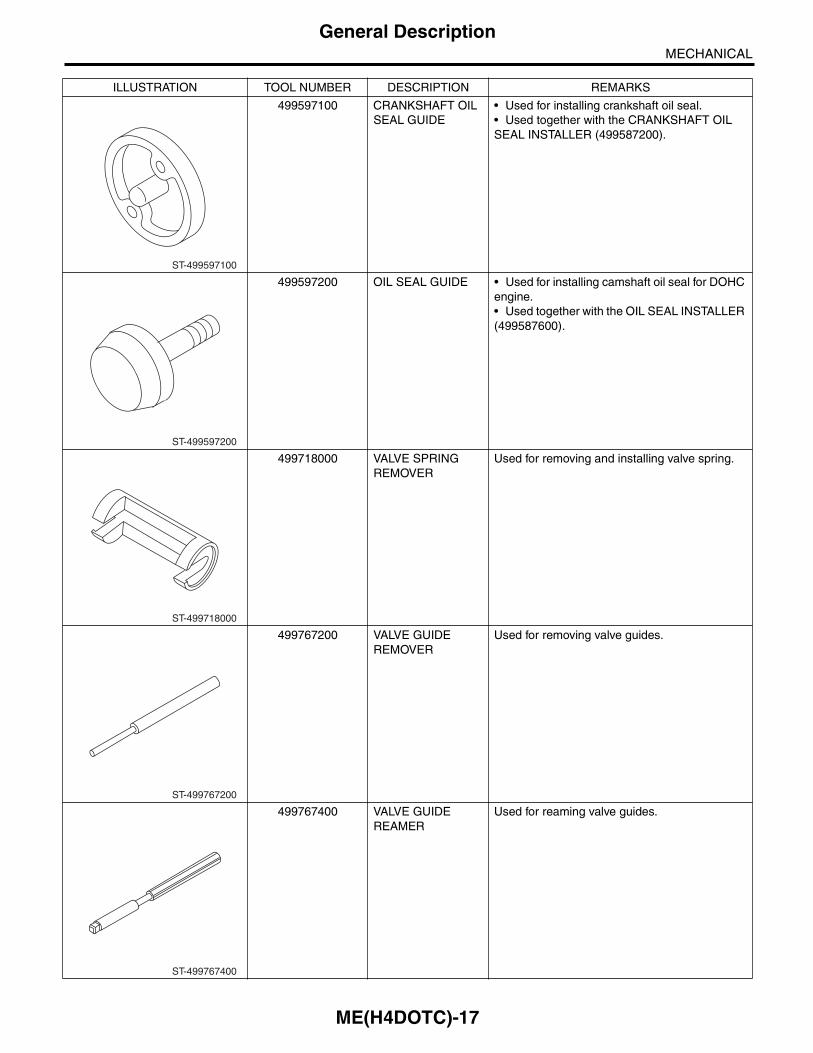
499597100 CRANKSHAFT OIL SEAL GUIDE
• Used for installing crankshaft oil seal.• Used together with the CRANKSHAFT OIL SEAL INSTALLER (499587200).
499597200 OIL SEAL GUIDE • Used for installing camshaft oil seal for DOHC engine.• Used together with the OIL SEAL INSTALLER (499587600).
499718000 VALVE SPRING REMOVER
Used for removing and installing valve spring.
499767200 VALVE GUIDE REMOVER
Used for removing valve guides.
499767400 VALVE GUIDE REAMER
Used for reaming valve guides.
ILLUSTRATION TOOL NUMBER DESCRIPTION REMARKS
ST-499597100
ST-499597200
ST-499718000
ST-499767200
ST-499767400

ME(H4DOTC)-18
General DescriptionMECHANICAL
499817100 ENGINE STAND • Stand used for engine disassembly and assembly.• Used together with the ENGINE STAND ADAPTER RH (498457000) & LH (498457100).
499977100 CRANK PULLEY WRENCH
Used to stop rotation of the crank pulley when loosening or tightening crank pulley bolts. (MT model)
499977400 CRANK PULLEY WRENCH
Used to stop rotation of the crank pulley when loosening or tightening crank pulley bolts. (AT model)
499977500 CAM SPROCKET WRENCH
Used for removing and installing intake cam sprocket.
499987500 CRANKSHAFT SOCKET
Used for rotating crankshaft.
ILLUSTRATION TOOL NUMBER DESCRIPTION REMARKS
ST-499817100
ST-499977100
ST-499977400
ST-499977500
ST-499987500

ME(H4DOTC)-19
General DescriptionMECHANICAL
2. GENERAL TOOL
18251AA020 VALVE GUIDE ADJUSTER
Used for installing intake and exhaust valve guides.
18371AA000 CONNECTOR REMOVER
Used for disconnecting the quick connector on the fuel return hose of the engine compartment.
42099AE000 QUICK CONNECTOR RELEASE
Used for disconnecting quick connector of the engine compartment.
1B021XU0 SUBARU SELECT MONITOR III KIT
Used for troubleshooting the electrical system.
TOOL NAME REMARKS
Compression gauge Used for measuring compression.
Timing light Used for measuring ignition timing.
Vacuum gauge Used for measuring intake manifold vacuum.
Oil pressure gauge Used for measuring engine oil pressure.
Fuel pressure gauge Used for measuring fuel pressure.
ILLUSTRATION TOOL NUMBER DESCRIPTION REMARKS
ST18251AA020
ST18371AA000
ST42099AE000
ST1B021XU0

ME(H4DOTC)-20
General DescriptionMECHANICAL
E: PROCEDUREIt is possible to conduct the following service proce-dures with engine on vehicle, however, the proce-dures described in this section are based on thecondition that the engine is removed from vehicle.• V-belt• Timing belt• Camshaft• Cylinder head

ME(H4DOTC)-21
CompressionMECHANICAL
2. CompressionA: INSPECTIONCAUTION:After warming-up, engine becomes very hot. Becareful not to burn yourself during measure-ment.1) After warming-up the engine, turn the ignitionswitch to OFF.2) Make sure that the battery is fully charged.3) Release the fuel pressure. <Ref. to FU(H4DOTC)-50, RELEASING OF FUEL PRESSURE, PROCE-DURE, Fuel.>4) Remove all the spark plugs.<Ref. to IG(H4DOTC)-4, REMOVAL, Spark Plug.>5) Fully open the throttle valve.6) Check the starter motor for satisfactory perfor-mance and operation.7) Hold the compression gauge tightly against thespark plug hole.
NOTE:When using a screw-in type compression gauge,the screw should be less than 18 mm (0.71 in) long.8) Crank the engine by the starter motor, and readthe maximum value on the gauge when the needleof gauge is steady.
9) Perform at least two measurements per cylinder,and make sure that the values are correct.
Compression (fully open throttle):Standard
981 — 1,177 kPa (10 — 12 kgf/cm2, 142 — 171 psi)
Difference between cylinders49 kPa (0.5 kgf/cm2, 7 psi), or less
10) After inspection, install the related parts in thereverse order of removal.
ME-03009

ME(H4DOTC)-22
Idle SpeedMECHANICAL
3. Idle SpeedA: INSPECTION1) Before checking the idle speed, check the fol-lowing item:
(1) Check the air cleaner element is free fromclogging, ignition timing is correct, spark plugsare in good condition, and hoses are connectedproperly.(2) Check the malfunction indicator light doesnot illuminate.
2) Warm-up the engine.3) Read the engine idle speed using Subaru SelectMonitor. <Ref. to EN(H4DOTC)(diag)-35, READCURRENT DATA FOR ENGINE (NORMALMODE), OPERATION, Subaru Select Monitor.>4) Check the idle speed when no-loaded. (Head-light, heater fan, rear defroster, radiator fan, A/Cand etc. are OFF)
Idle speed [No load and gears in neutral, “P” or “N” range]:
750±100 rpm5) Check the idle speed when loaded. (Turn the A/C switch to “ON” and operate the compressor for atleast one minute before measurement.)
Idle speed [A/C ON and gears in neutral, “P” or “N” range]:
800±100 rpm (MT model)825±100 rpm (AT model)
NOTE:Idle speed cannot be adjusted manually, becausethe idle speed is automatically adjusted. If the pre-scribed idle speed cannot be maintained, refer tothe General On-board Diagnosis Table under “En-gine Control System”. <Ref. to EN(H4DOTC)(di-ag)-2, Basic Diagnostic Procedure.>

ME(H4DOTC)-23
Ignition TimingMECHANICAL
4. Ignition TimingA: INSPECTIONCAUTION:After warming-up, engine becomes very hot. Becareful not to burn yourself at measurement.
1. METHOD WITH SUBARU SELECT MONITOR1) Before checking the ignition timing, check thefollowing item:
(1) Check the air cleaner element is free fromclogging, spark plugs are in good condition, andhoses are connected properly.(2) Check the malfunction indicator light doesnot illuminate.
2) Warm-up the engine.3) Read the ignition timing using Subaru SelectMonitor. <Ref. to EN(H4DOTC)(diag)-35, READCURRENT DATA FOR ENGINE (NORMALMODE), OPERATION, Subaru Select Monitor.>
Ignition timing [BTDC/rpm]:12°±10°/750 (MT Model)17°±10°/750 (AT Model)
If the timing is not correct, check the ignition controlsystem. Refer to “Engine Control System”. <Ref. toEN(H4DOTC)(diag)-2, Basic Diagnostic Proce-dure.>
2. METHOD WITH TIMING LIGHT1) Before checking the ignition timing, check thefollowing item:
(1) Check the air cleaner element is free fromclogging, spark plugs are in good condition, andhoses are connected properly.(2) Check the malfunction indicator light doesnot illuminate.
2) Warm-up the engine.3) Stop the engine, and turn the ignition switch toOFF.4) Remove the air intake duct.5) Disconnect the connectors of the mass air flowand intake air temperature sensor.6) Remove the air cleaner case and element.7) Connect the timing light to the power wire of #1ignition coil.8) Attach the air cleaner case, element and con-nector of mass air flow and intake air temperaturesensor.
9) Start the engine, turn the timing light to the crankpulley, and check the ignition timing by means ofcrank pulley indicator.
Ignition timing [BTDC/rpm]:12°±10°/750 (MT Model)17°±10°/750 (AT Model)
If the timing is not correct, check the ignition controlsystem. Refer to “Engine Control System”. <Ref. toEN(H4DOTC)(diag)-2, Basic Diagnostic Proce-dure.>

ME(H4DOTC)-24
Intake Manifold VacuumMECHANICAL
5. Intake Manifold VacuumA: INSPECTION1) Warm-up the engine.2) Disconnect the brake booster vacuum hose fromthe intake manifold, and then install the vacuumgauge.3) Keep the engine at idle speed and read the vac-uum gauge indication.By observing the gauge needle movement, the in-ternal condition of the engine can be diagnosed asdescribed below.
Vacuum pressure (at idling, A/C OFF):Less than –70.6 kPa (–530 mmHg, –20.85 inHg) (MT model)Less than –68.0 kPa (–510 mmHg, –20.08 inHg) (AT model)
ME-00801
Diagnosis of engine condition by measurement of intake manifold vacuum
Vacuum gauge indication Possible engine condition
1. Needle is steady but lower than normal position. This ten-dency becomes more evident as engine temperature rises.
Leakage around intake manifold gasket, or disconnected or damaged vacuum hose
2. Needle intermittently drops to position lower than normal position.
Leakage around cylinder
3. Needle drops suddenly and intermittently from normal posi-tion.
Sticky valve
4. When engine speed is gradually increased, needle begins to vibrate rapidly at certain speed, and then vibration increases as engine speed increases.
Weak or broken valve springs
5. Needle vibrates above and below normal position in narrow range.
Defective ignition system

ME(H4DOTC)-25
Engine Oil PressureMECHANICAL
6. Engine Oil PressureA: INSPECTION1) Disconnect the ground cable from the battery.
2) Remove the oil pressure switch. <Ref. toLU(H4DOTC)-18, REMOVAL, Oil Pressure Switch.>3) Connect the oil pressure gauge hose to cylinderblock.4) Connect the battery ground cable to the battery.
5) Start the engine, and measure the oil pressure.
Oil pressure:Standard
98 kPa (1.0 kgf/cm2, 14 psi) or more (at 600 rpm)294 kPa (3.0 kgf/cm2, 43 psi) or more (at 5,000 rpm)
• If the oil pressure is out of specification, check oilpump, oil filter and lubrication line. <Ref. toLU(H4DOTC)-20, INSPECTION, Engine Lubrica-tion System Trouble in General.>• If the oil pressure warning light is ON and oilpressure is within specification, check the oil pres-sure switch. <Ref. to LU(H4DOTC)-20, INSPEC-TION, Engine Lubrication System Trouble inGeneral.>
NOTE:Standard value is based on an engine oil tempera-ture of 80°C (176°F).6) After measuring the oil pressure, install the oilpressure switch. <Ref. to LU(H4DOTC)-18, IN-STALLATION, Oil Pressure Switch.>
IN-00203
IN-00203
ME-00196

ME(H4DOTC)-26
Fuel PressureMECHANICAL
7. Fuel PressureA: INSPECTIONCAUTION:• Before removing the fuel pressure gauge, re-lease the fuel pressure.• Be careful not to spill fuel.• Catch the fuel from hoses using a containeror cloth.
NOTE:If the fuel pressure is out of specification, check orreplace the pressure regulator and pressure regu-lator vacuum hose.1) Release the fuel pressure. <Ref. to FU(H4DOTC)-50, RELEASING OF FUEL PRESSURE, PROCE-DURE, Fuel.>2) Open the fuel filler flap lid, and remove the fuelfiller cap.3) Disconnect the fuel delivery hose from fueldamper valve, and connect fuel pressure gauge.
4) Install the fuse of fuel pump to the main fuse box.
5) Start the engine.6) Measure the fuel pressure while disconnectingpressure regulator vacuum hose from intake mani-fold.
NOTE:The fuel pressure gauge registers 10 to 20 kPa (0.1to 0.2 kgf/cm2, 1 to 3 psi) higher than standard val-ues during high-altitude operations.
Fuel pressure:Standard
284 — 314 kPa (2.9 — 3.2 kgf/cm2, 41 — 46 psi)
7) After connecting the pressure regulator vacuumhose, measure the fuel pressure.
NOTE:The fuel pressure gauge registers 10 to 20 kPa (0.1to 0.2 kgf/cm2, 1 to 3 psi) higher than standard val-ues during high-altitude operations.
Fuel pressure:Standard
230 — 260 kPa (2.35 — 2.65 kgf/cm2, 33 — 38 psi)
ME-03092
FU-01122

ME(H4DOTC)-27
Valve ClearanceMECHANICAL
8. Valve ClearanceA: INSPECTIONNOTE:Inspection and adjustment of valve clearanceshould be performed while engine is cold.1) Set the vehicle on a lift.2) Disconnect the ground cable from the battery.
3) Remove the air intake duct. <Ref. to IN(H4DOTC)-9, REMOVAL, Air Intake Duct.>4) Remove the bolt which secures timing belt coverRH.5) Lift up the vehicle.6) Remove the under cover.7) Loosen the remaining bolts which secure timingbelt cover RH, then remove the timing belt cover.8) Lower the vehicle.9) When inspecting #1 and #3 cylinders
(1) Remove the air cleaner case. <Ref. toIN(H4DOTC)-8, REMOVAL, Air Cleaner Case.>(2) Disconnect the connector of ignition coil.(3) Remove the ignition coil.(4) Place a suitable container under the vehicle.(5) Disconnect the PCV hose from the rockercover RH.(6) Remove the bolts, then remove the rockercover RH.
10) When inspecting #2 and #4 cylinders(1) Disconnect the battery cable, and then re-move the battery and battery carrier.(2) Remove the secondary air pump. <Ref. toEC(H4DOTC)-23, REMOVAL, Secondary AirPump.>(3) Disconnect the connector of ignition coil.(4) Remove the ignition coil.(5) Place a suitable container under the vehicle.(6) Disconnect the PCV hose from the rockercover LH.(7) Remove the bolts, then remove the rockercover LH.
11) Turn the crank pulley clockwise until the roundmark and arrow mark on the camshaft sprocket areset to position shown in the figure.
NOTE:Turn the crank pulley using a socket wrench.
12) Measure the #1 cylinder intake valve and #3cylinder exhaust valve clearance by using thick-ness gauge (A).
NOTE:• Insert a thickness gauge in a direction as hori-zontal as possible with respect to the valve lifter.• Lift up the vehicle and measure the exhaustvalve clearances.• If the measured value is not within specification,take notes of the value in order to adjust the valveclearance later on.
Valve clearance (inspection value):Intake
0.20+0.04–0.06 mm (0.0079+0.0016
–0.0024 in)Exhaust
0.35±0.05 mm (0.0138±0.0020 in)
13) If necessary, adjust the valve clearance. <Ref.to ME(H4DOTC)-28, ADJUSTMENT, Valve Clear-ance.>
IN-00203
ME-03171
ME-00019
( A )

ME(H4DOTC)-28
Valve ClearanceMECHANICAL
14) Further turn the crank pulley clockwise andthen measure the valve clearances again.
(1) Set the round mark and arrow mark on camsprocket to the position shown in the figure, andmeasure the #2 cylinder exhaust valve and #3cylinder intake valve clearances.
(2) Set the round mark and arrow mark on camsprocket to the position shown in the figure, andmeasure the #2 cylinder intake valve and #4cylinder exhaust valve clearances.
(3) Set the round mark and arrow mark on camsprocket to the position shown in the figure, andmeasure the #1 cylinder exhaust valve and #4cylinder intake valve clearances.
15) After inspection, install the related parts in thereverse order of removal.
B: ADJUSTMENTNOTE:Adjustment of valve clearance should be per-formed while engine is cold.1) Measure all the valve clearances. <Ref. toME(H4DOTC)-27, INSPECTION, Valve Clear-ance.>
NOTE:Record each valve clearance after measurement.
2) Remove the camshaft. <Ref. to ME(H4DOTC)-63, REMOVAL, Camshaft.>3) Remove the valve lifter.4) Measure the thickness of valve lifter using mi-crometer.
5) Select and install a valve lifter of suitable thick-ness from the following table, based on the mea-sured valve clearance and valve lifter thickness.
ME-03172
ME-03173
ME-03174
Unit: (mm)
Intake valve: S = (V + T) – 0.19Exhaust valve: S= (V + T) – 0.35
S: Valve lifter thickness requiredV: Measured valve clearanceT: Valve lifter thickness to be used
ME-00024
ME-00025

ME(H4DOTC)-29
Valve ClearanceMECHANICAL
Part No. Thickness mm (in)
13228 AB102 4.68 (0.1843)
13228 AB112 4.69 (0.1846)
13228 AB122 4.70 (0.1850)
13228 AB132 4.71 (0.1854)
13228 AB142 4.72 (0.1858)
13228 AB152 4.73 (0.1862)
13228 AB162 4.74 (0.1866)
13228 AB172 4.75 (0.1870)
13228 AB182 4.76 (0.1874)
13228 AB192 4.77 (0.1878)
13228 AB202 4.78 (0.1882)
13228 AB212 4.79 (0.1886)
13228 AB222 4.80 (0.1890)
13228 AB232 4.81 (0.1894)
13228 AB242 4.82 (0.1898)
13228 AB252 4.83 (0.1902)
13228 AB262 4.84 (0.1906)
13228 AB272 4.85 (0.1909)
13228 AB282 4.86 (0.1913)
13228 AB292 4.87 (0.1917)
13228 AB302 4.88 (0.1921)
13228 AB312 4.89 (0.1925)
13228 AB322 4.90 (0.1929)
13228 AB332 4.91 (0.1933)
13228 AB342 4.92 (0.1937)
13228 AB352 4.93 (0.1941)
13228 AB362 4.94 (0.1945)
13228 AB372 4.95 (0.1949)
13228 AB382 4.96 (0.1953)
13228 AB392 4.97 (0.1957)
13228 AB402 4.98 (0.1961)
13228 AB412 4.99 (0.1965)
13228 AB422 5.00 (0.1969)
13228 AB432 5.01 (0.1972)
13228 AB442 5.02 (0.1976)
13228 AB452 5.03 (0.1980)
13228 AB462 5.04 (0.1984)
13228 AB472 5.05 (0.1988)
13228 AB482 5.06 (0.1992)
13228 AB492 5.07 (0.1996)
13228 AB502 5.08 (0.2000)
13228 AB512 5.09 (0.2004)
13228 AB522 5.10 (0.2008)
13228 AB532 5.11 (0.2012)
13228 AB542 5.12 (0.2016)
13228 AB552 5.13 (0.2020)
13228 AB562 5.14 (0.2024)
13228 AB572 5.15 (0.2028)
13228 AB582 5.16 (0.2031)
13228 AB592 5.17 (0.2035)
13228 AB602 5.18 (0.2039)
13228 AB612 5.19 (0.2043)
13228 AB622 5.20 (0.2047)
13228 AB632 5.21 (0.2051)
13228 AB642 5.22 (0.2055)
13228 AB652 5.23 (0.2059)
13228 AB662 5.24 (0.2063)
13228 AB672 5.25 (0.2067)
13228 AB682 5.26 (0.2071)
13228 AB692 5.27 (0.2075)
13228 AB702 4.38 (0.1724)
13228 AB712 4.40 (0.1732)
13228 AB722 4.42 (0.1740)
13228 AB732 4.44 (0.1748)
13228 AB742 4.46 (0.1756)
13228 AB752 4.48 (0.1764)
13228 AB762 4.50 (0.1771)
13228 AB772 4.52 (0.1780)
13228 AB782 4.54 (0.1787)
13228 AB792 4.56 (0.1795)
13228 AB802 4.58 (0.1803)
13228 AB812 4.60 (0.1811)
13228 AB822 4.62 (0.1819)
13228 AB832 4.64 (0.1827)
13228 AB842 4.66 (0.1835)
13228 AB852 5.29 (0.2083)
13228 AB862 5.31 (0.2091)
13228 AB872 5.33 (0.2098)
13228 AB882 5.35 (0.2106)
13228 AB892 5.37 (0.2114)
13228 AB902 5.39 (0.2122)
13228 AB912 5.41 (0.2123)
13228 AB922 5.43 (0.2138)
13228 AB932 5.45 (0.2146)
13228 AB942 5.47 (0.2154)
13228 AB952 5.49 (0.2161)
13228 AB962 5.51 (0.2169)
13228 AB972 5.53 (0.2177)
13228 AB982 5.55 (0.2185)
13228 AB992 5.57 (0.2193)
13228 AC002 5.59 (0.2201)
13228 AC012 5.61 (0.2209)
13228 AC022 5.63 (0.2217)
13228 AC032 5.65 (0.2224)
Part No. Thickness mm (in)

ME(H4DOTC)-30
Valve ClearanceMECHANICAL
6) Install the camshaft. <Ref. to ME(H4DOTC)-64,INSTALLATION, Camshaft.>7) Install the cam sprocket. <Ref. to ME(H4DOTC)-60, INSTALLATION, Cam Sprocket.>8) Install the timing belt. <Ref. to ME(H4DOTC)-54,TIMING BELT, INSTALLATION, Timing Belt.>9) Measure all valves for valve clearance again atthis time. If the valve clearance is not within the ad-justment value, repeat the procedure over againfrom the first step.
Valve clearance (adjustment value):Intake
0.20+0.01–0.03 mm (0.0079+0.0004
–0.0012 in)Exhaust
0.35±0.02 mm (0.0138±0.0008 in)10) After measuring, install the related parts in thereverse order of removal.

ME(H4DOTC)-31
Engine AssemblyMECHANICAL
9. Engine AssemblyA: REMOVAL1) Set the vehicle on a lift.2) Change the bolt mounting position from (A) to(B), and completely open the front hood.
Tightening torque:7.5 N·m (0.76 kgf-m, 5.5 ft-lb)
3) Remove the V-belt covers.
4) Collect the refrigerant from the A/C system.<Ref. to AC-18, Refrigerant Recovery Procedure.>5) Release the fuel pressure. <Ref. toFU(H4DOTC)-50, RELEASING OF FUEL PRES-SURE, PROCEDURE, Fuel.>6) Disconnect the battery cable, and remove thebattery from the vehicle.7) Open the fuel filler flap lid, and remove the fuelfiller cap.8) Remove the air intake duct and air cleaner case.<Ref. to IN(H4DOTC)-9, REMOVAL, Air IntakeDuct.> <Ref. to IN(H4DOTC)-8, REMOVAL, AirCleaner Case.>9) Remove the intercooler. <Ref. to IN(H4DOTC)-11, REMOVAL, Intercooler.>10) Remove the radiator from the vehicle. <Ref. toCO(H4DOTC)-19, REMOVAL, Radiator.>11) Remove the coolant filler tank.<Ref. to CO(H4DOTC)-29, REMOVAL, CoolantFiller Tank.>12) Disconnect the A/C pressure hoses from A/Ccompressor. <Ref. to AC-35, REMOVAL, Hose andTube.>
13) Disconnect the following connectors and ca-bles.
(1) Engine harness connectors
(2) Engine ground terminal
(3) Generator connector and terminal
(4) A/C compressor connector
ME-03387
(A)
(B)
(A)
(B)
ME-03386
ME-03533
ME-00028
ME-03388
ME-03389

ME(H4DOTC)-32
Engine AssemblyMECHANICAL
14) Disconnect the following hoses.(1) Brake booster vacuum hose
(2) Heater inlet and outlet hoses15) Remove the power steering pump.
(1) Remove the front side belts. <Ref. toME(H4DOTC)-41, FRONT SIDE BELT, RE-MOVAL, V-belt.>(2) Disconnect the power steering pump switchconnector.
(3) Remove the power steering pump from theengine. <Ref. to PS-44, REMOVAL, Oil Pump.>
(4) Place the power steering pump on the rightside wheel apron.
16) Lift up the vehicle.17) Remove the front and center exhaust pipes.<Ref. to EX(H4DOTC)-6, REMOVAL, Front Ex-haust Pipe.> <Ref. to EX(H4DOTC)-8, REMOVAL,Center Exhaust Pipe.>
18) Disconnect the ground cable on the engineside.
19) Remove the bolts and nuts which hold the low-er side of transmission to the engine.• AT model
• MT model
FU-02341
FU-03022
ME-03083
ME-03376
ME-03377
AT-00108
MT-00077

ME(H4DOTC)-33
Engine AssemblyMECHANICAL
20) Remove the nuts which hold the engine mountto the front cross member.
21) Separate the torque converter clutch from driveplate. (AT model)
(1) Lower the vehicle.(2) Remove the service hole plug.(3) Remove the bolts which hold torque con-verter clutch to drive plate.(4) Remove other bolts while rotating the crank-shaft using socket wrench.
22) Remove the pitching stopper.
23) Attach ST to the fuel delivery pipe and push STin the direction of arrow mark to disconnect the fueldelivery hose.ST 42099AE000 QUICK CONNECTOR
RELEASE
CAUTION:• Be careful not to spill fuel.• Catch the fuel from hoses using a containeror cloth.
24) Disconnect the fuel return hose using the ST.ST 18371AA000 CONNECTOR REMOVER
CAUTION:• Be careful not to spill fuel.• Catch the fuel from hoses using a containeror cloth.
(1) Attach the ST to the fuel return pipe asshown in the figure.
LU-00223
ME-00044
LU-00221
(A) Fuel delivery hose
(B) Fuel return hose
(C) Evaporation hose
FU-03095
(A)
(B)
(C)
ST
FU-03092
ST

ME(H4DOTC)-34
Engine AssemblyMECHANICAL
(2) Insert the front side of ST into the quick con-nector.
(3) Insert the back side of ST into the quick con-nector and push ST in the direction of arrowmark to disconnect the fuel return hose.
25) Remove the clip and disconnect the evapora-tion hose from the fuel pipe.
26) Support the engine with a lifting device andwire ropes.
27) Support the transmission with a garage jack.
CAUTION:Doing this is very important to prevent thetransmission from lowering due to its ownweight.
28) Separation of engine and transmission.
CAUTION:Before removing the engine away from trans-mission, check to be sure no work has beenoverlooked.
(1) Remove the starter. <Ref. to SC(H4SO)-6,REMOVAL, Starter.>(2) Set the ST to torque converter clutch case.(AT model)
ST 498277200 STOPPER SET
FU-03113
ST
FU-03114
ST
FU-03105
LU-00222
(A) Transmission
(B) Garage jack
ME-00215
(B)
(A)
ME-00049
ST

ME(H4DOTC)-35
Engine AssemblyMECHANICAL
(3) Remove the bolts which hold the upper sideof the transmission to the engine.• AT model
• MT model
29) Remove the engine from vehicle.(1) Slightly raise the engine.(2) Raise the transmission with garage jack.(3) Move the engine horizontally until mainshaft is withdrawn from clutch cover.(4) Slowly move the engine away from enginecompartment.
NOTE:Be careful not to damage adjacent parts or bodypanels with crank pulley, oil level gauge, etc.30) Remove the engine mount from the engine.
B: INSTALLATION1) Install the engine mount onto the engine.
Tightening torque:35 N·m (3.6 kgf-m, 25.8 ft-lb)
2) Apply a small amount of grease to splines ofmain shaft. (MT model)3) Position the engine in engine compartment andalign it with transmission.
NOTE:Be careful not to damage adjacent parts or bodypanels with crank pulley, oil level gauge, etc.4) Tighten the bolts which hold upper side of trans-mission to engine.
Tightening torque:50 N·m (5.1 kgf-m, 36.9 ft-lb)
• AT model
• MT model
5) Remove the lifting device and wire ropes.
6) Remove the garage jack.
AT-00106
MT-01524
AT-00106
MT-01524
LU-00222

ME(H4DOTC)-36
Engine AssemblyMECHANICAL
7) Install the pitching stopper.
Tightening torque:T1: 50 N·m (5.1 kgf-m, 36.9 ft-lb)T2: 58 N·m (5.9 kgf-m, 42.8 ft-lb)
8) Remove the ST from the torque converter clutchcase. (AT model)
NOTE:Be careful not to drop the ST into the torque con-verter clutch case when removing the ST.ST 498277200 STOPPER SET9) Install the starter. <Ref. to SC(H4SO)-6, IN-STALLATION, Starter.>10) Install the torque converter clutch to drive plate.(AT model)
(1) Tighten the bolts which hold torque convert-er clutch to drive plate.(2) Tighten other bolts while rotating the crank-shaft using socket wrench.
NOTE:Be careful not to drop bolts into the torque convert-er clutch housing.
Tightening torque:25 N·m (2.5 kgf-m, 18.4 ft-lb)
(3) Fit the plug to service hole.
11) Install the power steering pump.(1) Install the power steering pump.
Tightening torque:Refer to “COMPONENT” of “Power Steering” for the tightening torque. <Ref. to PS-4, COM-PONENT, General Description.>
(2) Connect the power steering pump switchconnector.
(3) Install and adjust the front side belt. <Ref. toME(H4DOTC)-41, FRONT SIDE BELT, IN-STALLATION, V-belt.>
12) Lift up the vehicle.
LU-00224
T2
T1
ME-00044
ME-00037
FU-03022

ME(H4DOTC)-37
Engine AssemblyMECHANICAL
13) Tighten the bolts and nuts which hold lowerside of the transmission to engine.
Tightening torque:50 N·m (5.1 kgf-m, 36.9 ft-lb)
• AT model
• MT model
14) Tighten the nuts which hold the engine mountto the cross member.
NOTE:Make sure that the engine mount nuts (A) and loca-tor (B) are securely installed.
Tightening torque:85 N·m (8.7 kgf-m, 62.7 ft-lb)
15) Connect the ground cable.
Tightening torque:7.5 N·m (0.76 kgf-m, 5.5 ft-lb)
16) Install the front and center exhaust pipe.<Ref. to EX(H4DOTC)-9, INSTALLATION, CenterExhaust Pipe.> <Ref. to EX(H4DOTC)-7, INSTAL-LATION, Front Exhaust Pipe.>17) Lower the vehicle.18) Connect the following hoses.
(1) Fuel delivery hose, fuel return hose andevaporation hose(2) Heater inlet and outlet hoses(3) Brake booster vacuum hose
19) Connect the following connectors and termi-nals.
(1) Engine ground terminal
Tightening torque:14 N·m (1.4 kgf-m, 10.3 ft-lb)(2) Engine harness connectors(3) Generator connector and terminal
Tightening torque:15 N·m (1.5 kgf-m, 11.1 ft-lb)(4) A/C compressor connector
20) Install the intercooler. <Ref. to IN(H4DOTC)-12, INSTALLATION, Intercooler.>21) Install the A/C pressure hoses. <Ref. to AC-35,INSTALLATION, Hose and Tube.>22) Install the radiator. <Ref. to CO(H4DOTC)-20,INSTALLATION, Radiator.>23) Install the coolant filler tank. <Ref. toCO(H4DOTC)-29, INSTALLATION, Coolant FillerTank.>
AT-00108
MT-00077
ME-03460(A) (B)(B) (A)
ME-03376
ME-03377

ME(H4DOTC)-38
Engine AssemblyMECHANICAL
24) Install the air cleaner case and air intake duct.<Ref. to IN(H4DOTC)-8, INSTALLATION, Air Clean-er Case.> <Ref. to IN(H4DOTC)-9, INSTALLATION,Air Intake Duct.>25) Install the battery to the vehicle, and connectthe battery cables.26) Fill engine coolant. <Ref. to CO(H4DOTC)-13,FILLING OF ENGINE COOLANT, REPLACEMENT,Engine Coolant.>27) Charge the A/C system with refrigerant. <Ref.to AC-19, PROCEDURE, Refrigerant ChargingProcedure.>28) Check the ATF level and replenish it if neces-sary. (AT model) <Ref. to 4AT-26, INSPECTION,Automatic Transmission Fluid.>29) Install the V-belt cover.
Tightening torque:13 N·m (1.3 kgf-m, 9.6 ft-lb)
30) Change the bolt mounting position from (B) to(A), and close the front hood.
Tightening torque:7.5 N·m (0.76 kgf-m, 5.5 ft-lb)
31) Lower the vehicle from the lift.
C: INSPECTION1) Check that pipes, hoses, connectors and clampsare installed firmly.2) Check that the engine coolant is at specified lev-el.3) Check that the ATF is at specified level. (ATmodel)4) Start the engine and check for exhaust gas, en-gine coolant, leaks of fuel, etc. Also check for noiseand vibrations.
ME-03386
ME-03387
(A)
(B)
(A)
(B)

ME(H4DOTC)-39
Engine MountingMECHANICAL
10.Engine MountingA: REMOVAL1) Remove the engine unit. <Ref. to ME(H4DOTC)-31, REMOVAL, Engine Assembly.>2) Remove the engine mounting from engine as-sembly.
B: INSTALLATIONInstall in the reverse order of removal.
Tightening torque: 35 N·m (3.6 kgf-m, 25.8 ft-lb)
C: INSPECTIONMake sure that no crack or other damages do notexist.

ME(H4DOTC)-40
Preparation for OverhaulMECHANICAL
11.Preparation for OverhaulA: PROCEDURE1) After removing the engine from body, secure it toST in the following procedure.ST1 498457000 ENGINE STAND ADAPTER
RHST2 498457100 ENGINE STAND ADAPTER
LHST3 499817100 ENGINE STAND
2) In this section the procedures described undereach index are all connected and stated in order.The procedure for overhauling of the engine will becompleted when you go through all steps in theprocess.Therefore, in this section, to conduct the particularprocedure within the flow of a section, you need togo back and conduct the procedure described pre-viously in order to do that particular procedure.
ME-00057ST3
ST2
ST1

ME(H4DOTC)-41
V-beltMECHANICAL
12.V-beltA: REMOVALNOTE:Perform the work with the engine installed to bodywhen replacing a single part.
1. FRONT SIDE BELT1) Remove the V-belt covers.
2) Remove the air intake duct. <Ref. toIN(H4DOTC)-9, REMOVAL, Air Intake Duct.>3) Loosen the bolt (A).4) Loosen the slider bolt (B).5) Remove the front side belt (C).
2. REAR SIDE BELT1) Remove the front side belts. <Ref. toME(H4SO)-39, FRONT SIDE BELT, REMOVAL,V-belt.>2) Cut the rear side belt with a wire cutter, etc., anddiscard.
B: INSTALLATION1. FRONT SIDE BELTCAUTION:• When reusing the front side belt, wipe off anysand or water with a cloth.• Do not reuse the front side belt if there is anyoil, grease or coolant on the belt.• Be careful when touching the belt. If the endface of the belt is rubbed by hand, you may re-ceive injury from bared wires.1) Wipe off any sand, dust, oil or water from the pul-ley grooves with a cloth.2) Install the front side belt (C), and adjust the sliderbolt (B) so as to obtain the specified belt tension.<Ref. to ME(H4DOTC)-47, INSPECTION, V-belt.>3) Tighten the bolt (A).4) Tighten the slider bolt (B).
Tightening torque:Bolt (A)
25 N·m (2.5 kgf-m, 18.4 ft-lb)Slider bolt (B)
8 N·m (0.8 kgf-m, 5.9 ft-lb)
5) Install the air intake duct. <Ref. to IN(H4DOTC)-9, INSTALLATION, Air Intake Duct.>6) Install the V-belt cover.
Tightening torque:13 N·m (1.3 kgf-m, 9.6 ft-lb)
ME-03386
ME-03392
(B)(B) (A)(A)
(A)(A)(A) (C)
(B) (A)
ME-03343
ME-03392
(B)(B) (A)(A)
(A)(A)(A) (C)
(B) (A)
ME-03386

ME(H4DOTC)-42
V-beltMECHANICAL
2. REAR SIDE BELTCAUTION:• Always use new rear side belt.• Be careful that the new rear side belt does not come into contact with any oil, grease or coolant.• Be careful when touching the belt. If the end face of the belt is rubbed by hand, you may receive in-jury from bared wires.• When installing the rear side belt, always use the provided tools (belt stopper, belt guide, beltguide holder and bolt).
1) Wipe off any sand, dust, oil or water from the pul-ley grooves with a cloth.2) Wipe off any oil, water, mud or rust attached tothe front side of the crank pulley with a cloth.3) Turn the crank pulley to the right slowly, until thecrank pulley service hole near the top.
CAUTION:Never turn the crank pulley to the left.
4) Attach a new rear side belt on the A/C compres-sor belt.
(A) Rear side belt (C) Belt guide (E) Bolt
(B) Belt stopper (D) Belt guide holder
ME-03457
(A)
(B) (C) (D) (E)
ME-03500
ME-03501

ME(H4DOTC)-43
V-beltMECHANICAL
5) Insert the claw of the belt stopper (A) into thelower hole (B) on the compressor bracket as shownin the figure, and attach using bolt (C).
6) Mount the belt guide by matching to the belt lineon the front side belt of the crank pulley.
7) Insert the belt guide holder into the crank pulleyservice hole so as to clamp the belt guide.
NOTE:The longer side of the belt guide holder is the upperside.
8) Turn the crank pulley slowly to the right, and setthe belt guide at an approximately 45° position.
9) Place the rib face of the rear side belt onto thegrooves of the crank pulley, and sandwich the rearside belt with the belt guide holder.
10) Place the tool through the loop of the rear sidebelt, and set on the crank pulley belt.
ME-03502
(A)
(C)
(B)
ME-03503
ME-03504
ME-03505
45
ME-03506
ME-03507
NGNGGGGGGGGGGGGGGGGGGGGGGGGGGGGGGGGGGGGGGGGGGGGGGGGGGGGGGGGGGGGNNNNNNNNNNNNNNNGGGGGGGGNNNNNNNNNNNNNNNNNNNNNNNNNNNNNNNNNNNNNNNNNNNNNNNNNNNNNNNNNNNNNNNNNNNNNNNNNNOKOKOKOKOKKKOOOOKKKKKOOKKKKKKKKKKKKKKKKKKKKKKKKKKKKKKKKKKKKKKKKKKKKKKKKKKKKOOOOOOOOOOOOOOOOOOOOOOOOOOOOOOOOOKOKOKKKKKKKKOOOOOOOOOOOO

ME(H4DOTC)-44
V-beltMECHANICAL
11) While checking for the following, turn the crankpulley slowly to the right by approximately 90° andset the belt guide to the position shown in the fig-ure.
(1) The ribs of the rear side belt are properlyriding on the grooves of the A/C compressorpulley.
(2) The ribs of the rear side belt are properlyriding on the grooves of the crank pulley.
(3) The surface of the rear side belt is beingpressed by the belt stopper.
(4) The rear side belt is riding properly on thebelt guide.
(4)
(2)
(2)(1)
(2)(3)
ME-03508
90
NGME-03516
OKKKKKOKOOOO
NGME-03518
OK
ME-03513
ME-03531

ME(H4DOTC)-45
V-beltMECHANICAL
12) While checking for the following, turn the crankpulley slowly to the right by approximately 90° andset the belt guide to the position shown in the fig-ure.
(1) The rear side belt is not twisted.
(2) The ribs of the rear side belt are properlyriding on the grooves of the A/C compressorpulley.
(3) The ribs of the rear side belt are properlyriding on the grooves of the crank pulley.
(4) The surface of the rear side belt is beingpressed by the belt stopper.
(5) The rear side belt is riding properly on thebelt guide.
ME-03509
(3)
(5)
(1)
(2)
(4)
90
ME-03512
NGME-03516
OKKKKKOKOOOO
NGME-03518
OK
ME-03513
ME-03530

ME(H4DOTC)-46
V-beltMECHANICAL
13) Turn the crank pulley slowly to the right, and at-tach the rear side belt.
CAUTION:Because there is a possibility of damage to therear side belt, and the belt guide holder fallingoff, care must be taken to make sure that the to-tal of steps 8), 11), 12), and 13) does not exceed330°.
14) Remove the belt guide and belt guide holderfrom the crank pulley.
15) Remove the belt stopper from the compressorbracket.
CAUTION:Make sure to remove the belt stopper, as leav-ing it on can cause smoke, flames or belt break-age.
16) Make sure that the belt ribs are properly ridingon the grooves of the pulleys, and turn the crankpulley slowly to the right twice to break in the rearside belt.
17) Discard the provided tools (belt stopper, beltguide, belt guide holder, bolt). 18) Install the front side belt. <Ref. to ME(H4SO)-39, FRONT SIDE BELT, INSTALLATION, V-belt.>
330
ME-03510
ME-03526
ME-03525
ME-03511
360 x2

ME(H4DOTC)-47
V-beltMECHANICAL
C: INSPECTION1. FRONT SIDE BELT1) Replace the front side belt, if cracking, fraying orwear is found.2) Check the front side belt tension and adjust it if nec-essary by adjusting the generator installing position.
Front side belt tension (when using a belt ten-sion gauge):
When installing new parts:640 — 780 N (65 — 80 kgf, 144 — 175 lbf)
At inspection490 — 640 N (50 — 65 kgf, 110 — 144 lbf)
Front side belt tension (when not using a belttension gauge):
When installing new parts7 — 9 mm (0.276 — 0.354 in)
At inspection9 — 11 mm (0.354 — 0.433 in)
2. REAR SIDE BELTIf cracks, fraying or wear is found, and when abnor-mal noise is produced, replace the rear side belt.
NOTE:Because the rear side belt is a stretch type belt, it isnot necessary to check deflection and tension.
(A) Front side belt
(B) Rear side belt
C/P Crank pulley
GEN Generator
P/S Power steering oil pump pulley
A/C Air conditioning compressor pulley
(A) Front side belt
(B) Rear side belt
(C) 98 N (10 kgf, 22 lbf)
C/P Crank pulley
GEN Generator
P/S Power steering oil pump pulley
A/C Air conditioning compressor pulley
ME-03313
C/P
P/S A/CGEN
(A)
(B)
ME-03314
(A) (B)GEN
C/P
A/CP/S
(C)

ME(H4DOTC)-48
Crank PulleyMECHANICAL
13.Crank PulleyA: REMOVALNOTE:Perform the work with the engine installed to bodywhen replacing a single part.1) Remove the V-belts. <Ref. to ME(H4DOTC)-41,REMOVAL, V-belt.>2) Use the ST to lock the crank pulley, and removethe crank pulley bolts.ST 499977100 CRANK PULLEY WRENCH
(MT model)ST 499977400 CRANK PULLEY WRENCH
(AT model)
3) Remove the crank pulley.
B: INSTALLATION1. AT MODEL1) Install the crank pulley.2) Use the ST to lock the crank pulley, and attachthe crank pulley bolts.ST 499977400 CRANK PULLEY WRENCH
(1) Clean the crankshaft thread using com-pressed air.(2) Apply engine oil to the crank pulley bolt seatand thread.(3) Tighten the bolts temporarily with tighteningtorque of 44 N·m (4.5 kgf-m, 32.5 ft-lb).(4) Tighten the crank pulley bolts.
Tightening torque:130 N·m (13.3 kgf-m, 95.9 ft-lb)
3) Check that the tightening angle of the crank pul-ley bolt is 45° or more. Perform the following proce-dure when less than 45°.
CAUTION:If the tightening angle of crank pulley bolt isless than 45°, the bolt is damaged. In this case,the bolt must be replaced.
(1) Replace the crank pulley bolts and cleanthem.
Crank pulley bolt:Part No. 12369AA011(2) Clean the crankshaft thread using com-pressed air.(3) Apply engine oil to the crank pulley bolt seatand thread.(4) Tighten the bolts temporarily with tighteningtorque of 44 N·m (4.5 kgf-m, 32.5 ft-lb).(5) Tighten the crank pulley bolts 45° to 60°.
NOTE:Conduct the tightening procedures by confirmingthe turning angle of crank pulley bolt referring to thegauge indicated on timing belt cover.4) Install the V-belts. <Ref. to ME(H4DOTC)-41,INSTALLATION, V-belt.>
ME-03393ST
ME-03393ST

ME(H4DOTC)-49
Crank PulleyMECHANICAL
2. MT MODEL1) Install the crank pulley.2) Use the ST to lock the crank pulley, and attachthe crank pulley bolts.ST 499977100 CRANK PULLEY WRENCH
(1) Clean the crankshaft thread using com-pressed air.(2) Apply engine oil to the crank pulley bolt seatand thread.(3) Tighten the bolts temporarily with tighteningtorque of 44 N·m (4.5 kgf-m, 32.5 ft-lb).(4) Tighten the crank pulley bolts.
Tightening torque:180 N·m (18.4 kgf-m, 132.8 ft-lb)
3) Check that the tightening angle of the crank pul-ley bolt is 65° or more. Perform the following proce-dure when less than 65°.
CAUTION:If the tightening angle of crank pulley bolt isless than 65°, the bolt is damaged. In this case,the bolt must be replaced.
(1) Replace the crank pulley bolts and cleanthem.
Crank pulley bolt:Part No. 12369AA011(2) Clean the crankshaft thread using com-pressed air.(3) Apply engine oil to the crank pulley bolt seatand thread.(4) Tighten the bolts temporarily with tighteningtorque of 44 N·m (4.5 kgf-m, 32.5 ft-lb).(5) Tighten the crank pulley bolts 65° to 75°.
NOTE:Conduct the tightening procedures by confirmingthe turning angle of crank pulley bolt referring to thegauge indicated on timing belt cover.4) Install the V-belts. <Ref. to ME(H4DOTC)-41,INSTALLATION, V-belt.>
C: INSPECTION1) Check the V-belt is not worn or otherwise dam-aged.2) Check the tension of the front side belt. <Ref. toME(H4DOTC)-47, INSPECTION, V-belt.>
ME-03393ST

ME(H4DOTC)-50
Timing Belt CoverMECHANICAL
14.Timing Belt CoverA: REMOVALNOTE:Perform the work with the engine installed to bodywhen replacing a single part.1) Remove the secondary air pump. <Ref. toEC(H4DOTC)-23, REMOVAL, Secondary Air Pump.>2) Remove the V-belts. <Ref. to ME(H4DOTC)-41,REMOVAL, V-belt.>3) Remove the crank pulley.<Ref. to ME(H4DOTC)-48, REMOVAL, Crank Pul-ley.>4) Remove the timing belt cover LH (A).5) Remove the timing belt cover RH (B).6) Remove the front timing belt cover (C).
B: INSTALLATION1) Install the front timing belt cover (C).
Tightening torque:5 N·m (0.5 kgf-m, 3.7 ft-lb)
2) Install the timing belt cover RH (B).
Tightening torque:5 N·m (0.5 kgf-m, 3.7 ft-lb)
3) Install the timing belt cover LH (A).
Tightening torque:5 N·m (0.5 kgf-m, 3.7 ft-lb)
4) Install the crank pulley. <Ref. to ME(H4DOTC)-48, INSTALLATION, Crank Pulley.>5) Install the V-belts. <Ref. to ME(H4DOTC)-41,INSTALLATION, V-belt.>6) Install the secondary air pump. <Ref. toEC(H4DOTC)-23, INSTALLATION, Secondary AirPump.>
C: INSPECTIONCheck the timing belt cover for damage.
ME-00064(A)
(C)(B)
ME-00064(A)
(C)(B)

ME(H4DOTC)-51
Timing BeltMECHANICAL
15.Timing BeltA: REMOVALNOTE:Perform the work with the engine installed to bodywhen replacing a single part. For operation proce-dures, refer to “Timing Belt” in the PM section.<Ref. to PM-13, Timing Belt.>
1. TIMING BELT1) Remove the V-belts. <Ref. to ME(H4DOTC)-41,REMOVAL, V-belt.>2) Remove the crank pulley. <Ref. to ME(H4DOTC)-48, REMOVAL, Crank Pulley.>3) Remove the timing belt cover.<Ref. to ME(H4DOTC)-50, REMOVAL, Timing BeltCover.>4) Remove the timing belt guide. (MT model)
5) If the alignment mark or arrow mark (which indi-cates the direction of rotation) on timing belt fadeaway, put new marks before removing the timingbelt as shown in procedures below.
(1) Turn the crankshaft using ST, and align thealignment marks on crank sprocket, intake camsprocket LH, exhaust cam sprocket LH, intakecam sprocket RH and exhaust cam sprocketRH with notches of the timing belt cover andcylinder block.
ST 499987500 CRANKSHAFT SOCKET
ME-00230
ME-03124
ME-00728
ME-00729
ME-00231ST

ME(H4DOTC)-52
Timing BeltMECHANICAL
(2) Using white paint, put an alignment mark oran arrow mark on timing belts in relation to thecrank sprocket and cam sprockets.
Z1: 54.5 teethZ2: 51 teethZ3: 28 teeth
6) Remove the belt idler (A).
7) Remove the timing belt.
CAUTION:After the timing belt has been removed, never ro-tate the intake and exhaust sprocket. If the camsprocket is rotated, the intake and exhaust valveheads strike together and valve stems are bent.
2. AUTOMATIC BELT TENSION ADJUSTER ASSEMBLY AND BELT IDLER1) Remove the belt idler (B) and (C).
2) Remove the belt idler No. 2.
3) Remove the automatic belt tension adjuster as-sembly.
ME-00070
ME-03175
ME-03176
Z3Z1 Z2 Z3
(A)
(B)
(C)
ME-03129
(A)
(B)
(C)
ME-03129
ME-00075
ME-03130

ME(H4DOTC)-53
Timing BeltMECHANICAL
B: INSTALLATION1. AUTOMATIC BELT TENSION ADJUSTER ASSEMBLY AND BELT IDLER1) Prepare for installation of automatic belt tensionadjuster assembly.
CAUTION:• Always use a vertical type pressing tool tomove the adjuster rod down.• Do not use a lateral type vise.• Push the adjuster rod vertically.• Press-in the push adjuster rod gradually tak-ing three minutes or more.• Do not allow press pressure to exceed 9,807 N(1,000 kgf, 2,205 lbf).• Push in the adjuster rod to the end face of thecylinder. However, do not press the adjusterrod below the end face of the cylinder. Doing somay damage the cylinder.• Do not release the press pressure until stop-per pin is completely inserted.
(1) Attach the automatic belt tension adjusterassembly to vertical pressing tool.(2) Slowly push in the adjuster rod with a pres-sure of 165 N (16.8 kgf, 37.1 lb) or more untilthe adjuster rod is aligned with the stopper pinhole in the cylinder.
(3) With a 2 mm (0.08 in) dia. stopper pin or a 2 mm(nominal) dia. hex wrench inserted into the stopperpin hole in cylinder, secure the adjuster rod.
2) Install the automatic belt tension adjuster as-sembly.
Tightening torque:39 N·m (4.0 kgf-m, 28.8 ft-lb)
3) Install the belt idler No. 2.
Tightening torque:39 N·m (4.0 kgf-m, 28.8 ft-lb)
4) Install the belt idlers.
Tightening torque:39 N·m (4.0 kgf-m, 28.8 ft-lb)
ME-00239
ME-00350
ME-03131
ME-00075
ME-03449

ME(H4DOTC)-54
Timing BeltMECHANICAL
2. TIMING BELT1) Prepare for installation of the automatic belt ten-sion adjuster assembly. <Ref. to ME(H4DOTC)-53,AUTOMATIC BELT TENSION ADJUSTER AS-SEMBLY AND BELT IDLER, INSTALLATION,Timing Belt.>2) Align the mark (A) on crank sprocket with themark on oil pump cover at cylinder block.
3) Align the single line mark (A) on the exhaust camsprocket RH with notch (B) on the timing belt cover.
4) Align the single line mark (A) on the intake camsprocket RH with notch (B) on the timing belt cover.Make sure that the double lines (C) on the intakeand exhaust camshaft sprockets are aligned.
5) Align the single line mark (A) on exhaust camsprocket LH with notch (B) on the timing belt coverby turning the sprocket counterclockwise (asviewed from front of engine).
6) Align the single line mark (A) on intake camsprocket LH with notch (B) on the timing belt coverby turning the sprocket clockwise (as viewed fromfront of engine). Make sure the double line marks(C) on the intake and exhaust cam sprockets arealigned.
ME-00081
(A)
ME-00082
(A)
(B)
ME-03133
(B)
(C)
(A)
ME-00084
(B)
(A)
ME-03135
(A)(B)
(C)

ME(H4DOTC)-55
Timing BeltMECHANICAL
7) Make sure that the cam and crank sprockets arepositioned properly.
CAUTION:• Intake and exhaust camshafts for this DOHCengine can be independently rotated with thetiming belts removed. As can be seen from thefigure, if the intake and exhaust valves are liftedsimultaneously, the valve heads will interferewith each other, resulting in bent valves.
• When the timing belts are not installed, fourcamshafts are held at the “zero-lift” position,where all cams on camshafts do not push theintake and exhaust valves down. (Under thiscondition, all valves remain unlifted.)• When the camshafts are rotated to install thetiming belts, #2 intake and #4 exhaust cam ofcamshaft LH are held, pushing their corre-sponding valves down. (Under this condition,these valves are held lifted.) Camshaft RH areheld so that their cams do not push the valvesdown.• Camshafts LH must be rotated by the small-est possible angle from zero-lift position towhere the timing belt can be installed, in orderto prevent mutual interference of intake and ex-haust valve heads.
• Do not allow the camshafts to rotate in the di-rection shown in the upper figure. Doing thismay cause both the intake and exhaust valvesto lift simultaneously, resulting in mutual inter-ference of heads.
(A) Intake camshaft
(B) Exhaust camshaft
ME-00086
(A)
(B)
(A) Direction of rotation
(B) Timing belt installation position
(A)
(A)
(A)
(A)
(B)
(B)
GGGGGNGNNGNNGNNNNNNNNNNNNNNGNNGGGGGGGGGGGGGGGGGGGOKOOOOOOOOOOOOOOOOOOOOOKKKKKKKKKKKKKOKOOKKKK
ME-03177

ME(H4DOTC)-56
Timing BeltMECHANICAL
8) Install the timing belt.Align the alignment mark on the timing belt with marks on the sprockets in the alphabetical order shown inthe figure. While aligning marks, position the timing belt properly.
CAUTION:• If the timing belt slips by 1 or more teeth, the valve and piston may hit each other.• Make sure that the direction of belt rotation is correct.
(1) Arrow mark (4) 54.5 tooth length (7) Install it in the end
(2) Timing belt (5) 51 tooth length
(3) 28 tooth length (6) 28 tooth length
ME-03137
(1) (2)
(5) (6)(4)
(D)(A)
(C)
(B)
(E)
(3)
RH-IN
RH-EX LH-EX
LH-IN
(7)

ME(H4DOTC)-57
Timing BeltMECHANICAL
9) Install the belt idlers.
Tightening torque:39 N·m (4.0 kgf-m, 28.8 ft-lb)
NOTE:Make sure that the marks on the timing belt andsprockets are aligned.
10) After ensuring that the marks on the timing beltand sprockets are aligned, remove the stopper pinfrom tensioner adjuster.
11) Install the timing belt guide. (MT model)(1) Temporarily tighten the bolts mounting thetiming belt guide.
NOTE:• Before attaching the bolts, clean the bolt holes ofthe timing belt cover.• Apply liquid gasket to the threaded portion ofcam sprocket. (when reusing bolts)
Liquid gasket:THREE BOND 1324 (Part No. 004403042) or equivalent
(2) Check and adjust the clearance betweentiming belt and timing belt guide using a thick-ness gauge.
Clearance:1.0±0.5 mm (0.039±0.020 in)
ME-00090
ME-00245
ME-00230
ME-00246
ME-03138
ME-00731
ME-00732

ME(H4DOTC)-58
Timing BeltMECHANICAL
(3) Tighten the bolts mounting the timing beltguide.
Tightening torque:9.75 N·m (1.0 kgf-m, 7.2 ft-lb)
Tightening torque:6.4 N·m (0.65 kgf-m, 4.7 ft-lb)
Tightening torque:6.4 N·m (0.65 kgf-m, 4.7 ft-lb)
Tightening torque:6.4 N·m (0.65 kgf-m, 4.7 ft-lb)
12) Install the timing belt cover.<Ref. to ME(H4DOTC)-50, INSTALLATION, Tim-ing Belt Cover.>13) Install the crank pulley.<Ref. to ME(H4DOTC)-48, INSTALLATION, CrankPulley.>14) Install the V-belts. <Ref. to ME(H4DOTC)-41,INSTALLATION, V-belt.>
C: INSPECTION1. TIMING BELT1) Check the timing belt teeth for breaks, cracks orwear. If any fault is found, replace the timing belt.2) Check the condition on the back surface of thetiming belt. If cracks are found, replace the timingbelt.
CAUTION:• Be careful not to let oil, grease or coolantcontact the timing belt. Remove quickly andthoroughly if this happens.• Do not bend the timing belt sharply.
In radial diameter h:60 mm (2.36 in) or more
ME-00247
ME-03124
ME-00728
ME-00729
ME-00248
h

ME(H4DOTC)-59
Timing BeltMECHANICAL
2. AUTOMATIC BELT TENSION ADJUSTER1) Visually check the oil seals for leaks, and rodends for abnormal wear and scratches. If neces-sary, replace the automatic belt tension adjusterassembly.
NOTE:Slight traces of oil on the oil seal of the rod does notindicate a problem.2) Check that the adjuster rod does not move whena pressure of 165 N (16.8 kgf, 37.1 lbf) is applied toit. In this check, it is possible to check the stiffnessof the adjuster rod.3) If the adjuster rod is not stiff and moves freelywhen applying 165 N (16.8 kgf, 37.1 lbf), check itusing the following procedures:
(1) Slowly press the adjuster rod down to theend surface of cylinder. Repeat this operationtwo to three times.(2) With the adjuster rod moved all the way up,apply a pressure of 165 N (16.8 kgf, 37.1 lbf) toit. Check the adjuster rod stiffness.(3) If the adjuster rod is not stiff and movesdown, replace the automatic belt tension adjust-er assembly with a new part.
CAUTION:• Always use a vertical type pressing tool tomove the adjuster rod down.• Do not use a lateral type vise.• Push the adjuster rod vertically.• Press-in the push adjuster rod gradually tak-ing three minutes or more.• Do not allow press pressure to exceed 9,807 N(1,000 kgf, 2,205 lbf).• Push in the adjuster rod to the end face of thecylinder. However, do not press the adjusterrod below the end face of the cylinder. Doing somay damage the cylinder.4) Measure the amount of rod protrusion “H” fromthe end surface of body. If it is not within the spec-ified range, replace with a new part.
Amount of rod protrusion H:5.2 — 6.2 mm (0.205 — 0.244 in)
3. BELT TENSION PULLEY1) Check the mating surfaces of timing belt andcontact point of adjuster rod for abnormal wear orscratches. Replace the automatic belt tension ad-juster assembly with a new part if faulty.2) Check the belt tension pulley for smooth rota-tion. Replace the automatic belt tension adjusterassembly with a new part if abnormal noise or ex-cessive play occurs.3) Check the belt tension pulley for grease leakage.
4. BELT IDLER1) Check the belt idler for smooth rotation. Replaceif noise or excessive play occurs.2) Check the outer contacting surfaces of idler pul-ley for abnormal wear and scratches.3) Check the belt idler for grease leakage.
ME-00249
H

ME(H4DOTC)-60
Cam SprocketMECHANICAL
16.Cam SprocketA: REMOVALNOTE:Perform the work with the engine installed to bodywhen replacing a single part.1) Remove the V-belts. <Ref. to ME(H4DOTC)-41,REMOVAL, V-belt.>2) Remove the crank pulley.<Ref. to ME(H4DOTC)-48, REMOVAL, Crank Pul-ley.>3) Remove the timing belt cover.<Ref. to ME(H4DOTC)-50, REMOVAL, Timing BeltCover.>4) Remove the timing belt.<Ref. to ME(H4DOTC)-51, REMOVAL, TimingBelt.>5) Remove the actuator cover of the intake camsprocket.6) Fasten the cam sprocket and remove from thecam shaft using ST.ST 499207400 CAM SPROCKET WRENCH
ST 499977500 CAM SPROCKET WRENCH
B: INSTALLATION1) Fasten the cam sprocket and install to the camshaft using ST.
NOTE:Do not confuse cam sprockets (LH) and (RH) dur-ing installation.ST 499207400 CAM SPROCKET WRENCH
Tightening torque: Tighten to 30 N·m (3.1 kgf-m, 22.1 ft-lb) of torque, and then tighten further by 45°.
ST 499977500 CAM SPROCKET WRENCH
Tightening torque:Tighten to 30 N·m (3.1 kgf-m, 22.1 ft-lb) of torque, and then tighten further by 45°.
2) Attach the actuator cover of the intake camsprocket.
NOTE:Use new O-rings.
Tightening torque:3.4 N·m (0.3 kgf-m, 2.5 ft-lb)
3) Install the timing belt. <Ref. to ME(H4DOTC)-53,INSTALLATION, Timing Belt.>4) Install the timing belt cover. <Ref. toME(H4DOTC)-50, INSTALLATION, Timing BeltCover.>5) Install the crank pulley. <Ref. to ME(H4DOTC)-48, INSTALLATION, Crank Pulley.>6) Install the V-belts. <Ref. to ME(H4DOTC)-41,INSTALLATION, V-belt.>
ME-03282ST
ME-03283
ST
ME-03282ST
ME-03283
ST
ME(H4DOTC)-61
Cam SprocketMECHANICAL
C: INSPECTION1) Check the cam sprocket teeth for abnormal wearand scratches.2) Make sure there is no free play between camsprocket and key.

ME(H4DOTC)-62
Crank SprocketMECHANICAL
17.Crank SprocketA: REMOVALNOTE:Perform the work with the engine installed to bodywhen replacing a single part.1) Remove the V-belts. <Ref. to ME(H4DOTC)-41,REMOVAL, V-belt.>2) Remove the crank pulley.<Ref. to ME(H4DOTC)-48, REMOVAL, Crank Pul-ley.>3) Remove the timing belt cover.<Ref. to ME(H4DOTC)-50, REMOVAL, Timing BeltCover.>4) Remove the timing belt.<Ref. to ME(H4DOTC)-51, REMOVAL, TimingBelt.>5) Remove the crank sprocket.
B: INSTALLATION1) Install the crank sprocket.
2) Install the timing belt.<Ref. to ME(H4DOTC)-53, INSTALLATION, Tim-ing Belt.>3) Install the timing belt cover. <Ref. toME(H4DOTC)-50, INSTALLATION, Timing BeltCover.>4) Install the crank pulley. <Ref. to ME(H4DOTC)-48, INSTALLATION, Crank Pulley.>5) Install the V-belts. <Ref. to ME(H4DOTC)-41,INSTALLATION, V-belt.>
C: INSPECTION1) Check the crank sprocket teeth for abnormalwear and scratches.2) Make sure there is no free play between cranksprocket and key.3) Check the crank sprocket protrusion used forsensor for damage and contamination of foreignmatter.
ME-00103
ME-00103

ME(H4DOTC)-63
CamshaftMECHANICAL
18.CamshaftA: REMOVALNOTE:Perform the work with the engine installed to bodywhen replacing a single part. Refer to “Valve Clear-ance” for preparation. <Ref. to ME(H4DOTC)-27,INSPECTION, Valve Clearance.>1) Remove the V-belts. <Ref. to ME(H4DOTC)-41,REMOVAL, V-belt.>2) Remove the crank pulley. <Ref. toME(H4DOTC)-48, REMOVAL, Crank Pulley.>3) Remove the timing belt cover.<Ref. to ME(H4DOTC)-50, REMOVAL, Timing BeltCover.>4) Remove the timing belt. <Ref. to ME(H4DOTC)-51, REMOVAL, Timing Belt.>5) Remove the cam sprocket. <Ref. toME(H4DOTC)-60, REMOVAL, Cam Sprocket.>6) Disconnect the oil flow control solenoid valveconnector.
7) Remove the timing belt cover No. 2 LH.
8) Remove the timing belt cover No. 2 RH.
NOTE:Do not damage or lose the seal rubber when re-moving the timing belt covers.
9) Remove the tensioner bracket.
10) Remove the ignition coil.11) Disconnect the PCV hose from the rocker cov-er.12) Remove the rocker cover and gasket.13) Remove the oil pipe.ME-03094
ME-00106(A) Union screw with filter (with protrusion)
(B) Union screw without filter (without protrusion)
(C) Oil pipe
ME-00107
ME-00105
(A)
(B)
ME-03555
(C)

ME(H4DOTC)-64
CamshaftMECHANICAL
14) Loosen the front camshaft cap upper area andintake camshaft cap bolts equally, a little at a timein alphabetical order as shown in the figure.
15) Loosen the front camshaft cap lower area andexhaust camshaft cap bolts equally, a little at a timein alphabetical order as shown in the figure.
16) Remove the front camshaft cap.17) Remove the intake camshaft caps and intakecamshaft.18) Remove the exhaust camshaft caps and ex-haust camshaft.
NOTE:Arrange camshaft caps in order so that they can beinstalled in their original positions.19) Remove the oil seal.
NOTE:Do not scratch the journal surface when removingthe oil seal.20) Similarly, remove the camshaft RH and relatedparts.
B: INSTALLATION1) Install the camshaft. Apply engine oil to the cylinder head at camshaftjournal installation location before installing thecamshaft. Install the camshaft so that each valve isclose to or in contact with base circle of the camlobe.
NOTE:• Set the camshaft to the position shown in the fig-ure.• When set at the position shown in the figure, it isnot necessary to rotate camshaft RH when install-ing the timing belt, but it is necessary to rotate cam-shaft LH slightly.
Intake camshaft LH:Rotate 80° clockwise.
Exhaust camshaft LH:Rotate 45° counterclockwise.
ME-00771
(A)(E)
(F)(B) (D)
(C)
ME-00772
(A)(E)
(F)(B) (D)
(C)
A Cylinder head LH
B Cylinder head RH
(a) Intake camshaft
(b) Exhaust camshaft
ME-00111
11
11
77.5
77.5(a)
(b)(a)
(b)
A
B

ME(H4DOTC)-65
CamshaftMECHANICAL
2) Install the camshaft cap.(1) Apply small amount of liquid gasket to themating surface of cap.
NOTE:• Install within 5 min. after applying liquid gasket.• Do not apply liquid gasket excessively. Applyingexcessively may cause excess gasket to come outand flow toward oil seal, resulting in oil leak.
Liquid gasket:THREE BOND 1217G (Part No. K0877Y0100) or equivalent
(2) Apply a thin coat of engine oil to the capjournal surface, and install the camshaft cap tothe camshaft.(3) Gradually tighten the camshaft cap in atleast two steps, in alphabetical order shown inthe figure, and then tighten to the specifiedtorque.
Tightening torque:T1: 9.75 N·m (1.0 kgf-m, 7.2 ft-lb)T2: 20 N·m (2.0 kgf-m, 14.8 ft-lb)
(4) After tightening the camshaft cap, ensurethe camshaft rotates only slightly while holdingit at base circle.
3) Apply a coat of engine oil to the camshaft oil sealperiphery and oil seal lips, then install the oil sealon the camshaft using ST1 and ST2.
NOTE:Use a new oil seal.ST1 499587600 OIL SEAL INSTALLERST2 499597200 OIL SEAL GUIDE
4) Install the oil pipe.
NOTE:Make sure not to mix up the union screws with filterand without filter as their installation positions aredifferent.
Tightening torque:29 N·m (3.0 kgf-m, 21.4 ft-lb)
5) Similarly, install the parts on right-hand side.6) Install the tensioner bracket.
Tightening torque:24.5 N·m (2.5 kgf-m, 18.1 ft-lb)
ME-00773
ME-02379
(G)(C)
(A) (K)
(L)
T1
(F)(E)
T2
T2(B) (J)
(H) (D) (I)
T1
(A) Union screw with filter (with protrusion)
(B) Union screw without filter (without protrusion)
(C) Oil pipe
ME-00116
ST1
ST2
(A)
(B)
ME-03555
(C)
ME-00105
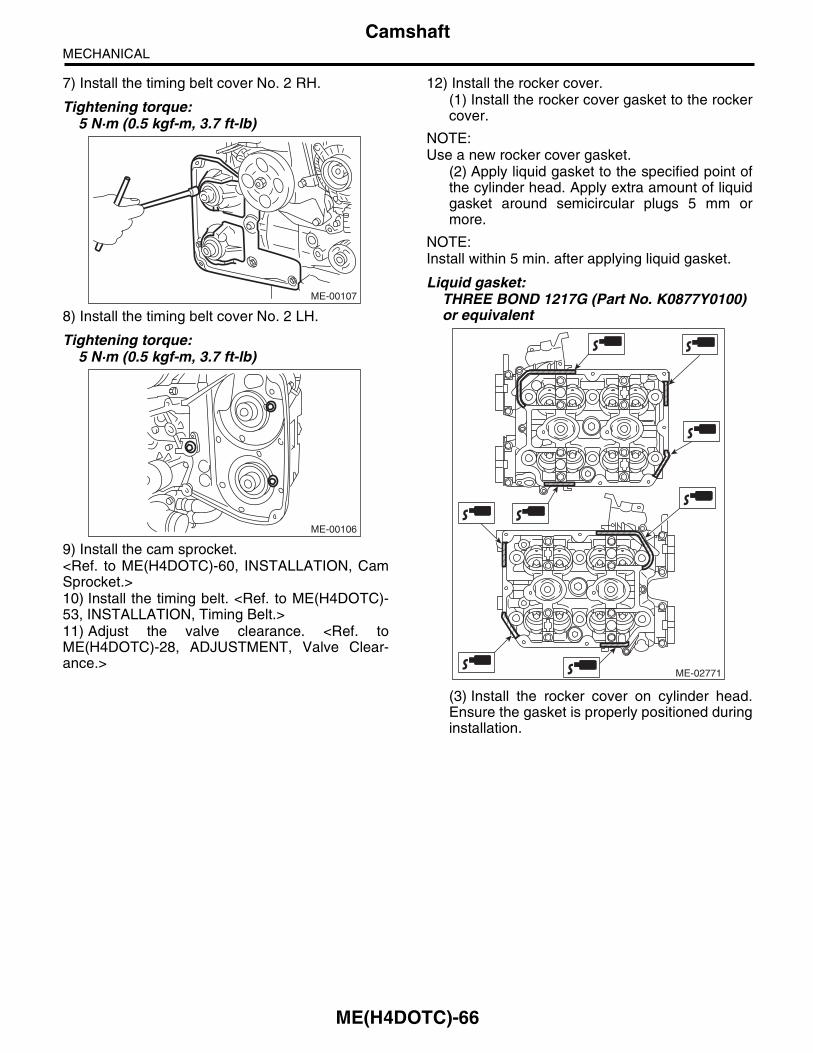
ME(H4DOTC)-66
CamshaftMECHANICAL
7) Install the timing belt cover No. 2 RH.
Tightening torque:5 N·m (0.5 kgf-m, 3.7 ft-lb)
8) Install the timing belt cover No. 2 LH.
Tightening torque:5 N·m (0.5 kgf-m, 3.7 ft-lb)
9) Install the cam sprocket.<Ref. to ME(H4DOTC)-60, INSTALLATION, CamSprocket.>10) Install the timing belt. <Ref. to ME(H4DOTC)-53, INSTALLATION, Timing Belt.>11) Adjust the valve clearance. <Ref. toME(H4DOTC)-28, ADJUSTMENT, Valve Clear-ance.>
12) Install the rocker cover.(1) Install the rocker cover gasket to the rockercover.
NOTE:Use a new rocker cover gasket.
(2) Apply liquid gasket to the specified point ofthe cylinder head. Apply extra amount of liquidgasket around semicircular plugs 5 mm ormore.
NOTE:Install within 5 min. after applying liquid gasket.
Liquid gasket:THREE BOND 1217G (Part No. K0877Y0100) or equivalent
(3) Install the rocker cover on cylinder head.Ensure the gasket is properly positioned duringinstallation.
ME-00107
ME-00106
ME-02771

ME(H4DOTC)-67
CamshaftMECHANICAL
(4) Temporarily tighten the rocker cover tight-ening bolt in alphabetical sequence shown inthe figure, and then tighten to specified torquein alphabetical order.
Tightening torque:6.4 N·m (0.65 kgf-m, 4.7 ft-lb)
13) Connect the PCV hose to the rocker cover.14) Connect the connector to the oil flow control so-lenoid valve.
15) Tighten the ignition coil.16) Install the timing belt cover.<Ref. to ME(H4DOTC)-50, INSTALLATION, Tim-ing Belt Cover.>17) Install the crank pulley.<Ref. to ME(H4DOTC)-48, INSTALLATION, CrankPulley.>18) Install the V-belts. <Ref. to ME(H4DOTC)-41,INSTALLATION, V-belt.>
C: INSPECTION1) Measure the bend, and repair or replace if nec-essary.
Service limit:0.020 mm (0.0079 in) or less
2) Check the journal for damage and wear. Re-place if faulty.3) Check the cutout portion used for camshaft sen-sor for damage. Replace if faulty.4) Measure the outside diameter of camshaft jour-nal. If the journal diameter is not within the standardvalue, check the oil clearance.
5) Measure the camshaft journal oil clearance.(1) Clean the camshaft cap and cylinder headcamshaft journal. (2) Place the camshaft on the cylinder head.(Without installing the valve lifter)(3) Place a plastigauge across each camshaftjournals.(4) Gradually tighten the camshaft cap in atleast two steps, in alphabetical order shown inthe figure, and then tighten to the specifiedtorque. Do not turn the camshaft.
Tightening torque:T1: 9.75 N·m (1.0 kgf-m, 7.2 ft-lb)T2: 20 N·m (2.0 kgf-m, 14.8 ft-lb)
(5) Remove the camshaft cap.
ME-00777
(E)
(F)
(H)
(G)
(D),(L)
(A),(I)
(C),(K)
(B),(J)
ME-03094
Camshaft journal
Front Center, rear
Standardmm (in)
37.946 — 37.963 (1.4939 — 1.4946)
29.946 — 29.963 (1.1790 — 1.1796)
ME-00118
ME-02379
(G)(C)
(A) (K)
(L)
T1
(F)(E)
T2
T2(B) (J)
(H) (D) (I)
T1

ME(H4DOTC)-68
CamshaftMECHANICAL
(6) Measure the widest point of the plastigaugeon each journal. If oil clearance exceeds thestandard, replace the camshaft. If necessary,replace the camshaft caps and cylinder head asa set.
Standard:0.037 — 0.072 mm (0.0015 — 0.0028 in)
(7) Completely remove the plastigauge.6) Check the cam face condition; remove the minorfaults by grinding with oil stone. Measure the camheight H. If it exceeds the standard or offset wearoccurs, replace it.
Cam height H:
StandardIntake
46.55 — 46.65 mm (1.833 — 1.837 in)Exhaust
46.75 — 46.85 mm (1.841 — 1.844 in)
Cam base circle diameter A:37.0 mm (1.457 in)
7) Measure the thrust clearance of camshaft withsetting the dial gauge at end of camshaft. If thethrust clearance is not within the standard or thereis offset wear, replace the camshaft caps and cylin-der head as a set. If necessary replace the cam-shaft.
Standard:0.068 — 0.116 mm (0.0027 — 0.0047 in)
ME-00119
ME-00276
H
A
ME-00121

ME(H4DOTC)-69
Cylinder HeadMECHANICAL
19.Cylinder HeadA: REMOVALNOTE:Perform the work with the engine installed to bodywhen replacing a single part. Refer to “Valve Clear-ance” for preparation. <Ref. to ME(H4DOTC)-27,INSPECTION, Valve Clearance.>1) Remove the V-belts. <Ref. to ME(H4DOTC)-41,REMOVAL, V-belt.>2) Remove the intake manifold.<Ref. to FU(H4DOTC)-15, REMOVAL, Intake Man-ifold.>3) Remove the crank pulley.<Ref. to ME(H4DOTC)-48, REMOVAL, Crank Pul-ley.>4) Remove the timing belt cover.<Ref. to ME(H4DOTC)-50, REMOVAL, Timing BeltCover.>5) Remove the timing belt.<Ref. to ME(H4DOTC)-51, REMOVAL, Timing Belt.>6) Remove the cam sprocket.<Ref. to ME(H4DOTC)-60, REMOVAL, Cam Sprock-et.>7) Remove the bolt which installs the A/C compres-sor bracket on cylinder head.8) Remove the secondary air combination valve.<Ref. to EC(H4DOTC)-24, REMOVAL, SecondaryAir Combination Valve.>9) Remove the camshaft. <Ref. to ME(H4DOTC)-63, REMOVAL, Camshaft.>10) Remove the oil level gauge guide. (LH side)11) Remove the cylinder head bolts in alphabeticalorder shown in the figure.
NOTE:Leave the bolts (A) and (D) engaged by three orfour threads to prevent the cylinder head from fall-ing.
12) While tapping the cylinder head with a plastichammer, separate it from cylinder block. Removethe bolts (A) and (D) to remove cylinder head.
13) Remove the cylinder head gasket.
CAUTION:Be careful not to scratch the mating surface ofcylinder head and cylinder block.14) Similarly, remove the right side cylinder head.
ME-00122
(B) (C)
(D)
(E)
(F) (A)
ME-00122
(B) (C)
(D)
(E)
(F) (A)

ME(H4DOTC)-70
Cylinder HeadMECHANICAL
B: INSTALLATION1) Install the cylinder head and gaskets on cylinderblock.
CAUTION:Be careful not to scratch the mating surface ofcylinder head and cylinder block.
NOTE:Use a new cylinder head gasket.2) Tighten the cylinder head bolts.
(1) Apply a thin coat of engine oil to washer andbolt thread.(2) Tighten all bolts to 29 N·m (3.0 kgf-m, 21.4 ft-lb)in alphabetical order.(3) Further tighten all bolts to 69 N·m (7.0 kgf-m,50.9 ft-lb) in alphabetical order.(4) Loosen all the bolts by 180° in the reverseorder of installing, and loosen them further by180°.(5) Tighten all bolts to 49 N·m (5.0 kgf-m, 36.1 ft-lb)in alphabetical order.(6) Tighten all bolts by 80 to 90° in alphabeticalorder.(7) Tighten all bolts by 40 to 45° in alphabeticalorder.
CAUTION:The tightening angle of the bolt should not ex-ceed 45°.
(8) Further tighten the bolts (A) and (B) by 40 —45°.
CAUTION:Make sure the total “re-tightening angle” of thestep (7) and (8) does not exceed 90°.
3) Install the oil level gauge guide. (LH side)
Tightening torque:6.4 N·m (0.65 kgf-m, 4.7 ft-lb)
4) Install the camshaft. <Ref. to ME(H4DOTC)-64,INSTALLATION, Camshaft.>5) Install the secondary air combination valve.<Ref. to EC(H4DOTC)-25, INSTALLATION, Sec-ondary Air Combination Valve.>
6) Install the bolt of A/C compressor bracket to thecylinder head.
Tightening torque: 36 N·m (3.7 kgf-m, 26.6 ft-lb)
7) Install the cam sprocket.<Ref. to ME(H4DOTC)-60, INSTALLATION, CamSprocket.>8) Install the timing belt.<Ref. to ME(H4DOTC)-53, INSTALLATION, Tim-ing Belt.>9) Adjust the valve clearance. <Ref. to ME(H4DOTC)-28, ADJUSTMENT, Valve Clearance.>10) Install the rocker cover.
(1) Install the rocker cover gasket to the rockercover.
NOTE:Use a new rocker cover gasket.
(2) Apply liquid gasket to the specified point ofthe cylinder head. Apply extra amount of liquidgasket around semicircular plugs 5 mm ormore.
NOTE:Install within 5 min. after applying liquid gasket.
Liquid gasket:THREE BOND 1217G (Part No. K0877Y0100) or equivalent
(3) Install the rocker cover on cylinder head.Ensure the gasket is properly positioned duringinstallation.
ME-00123
(B)
(C)
(D)(E)
(F)(A)
ME-02771
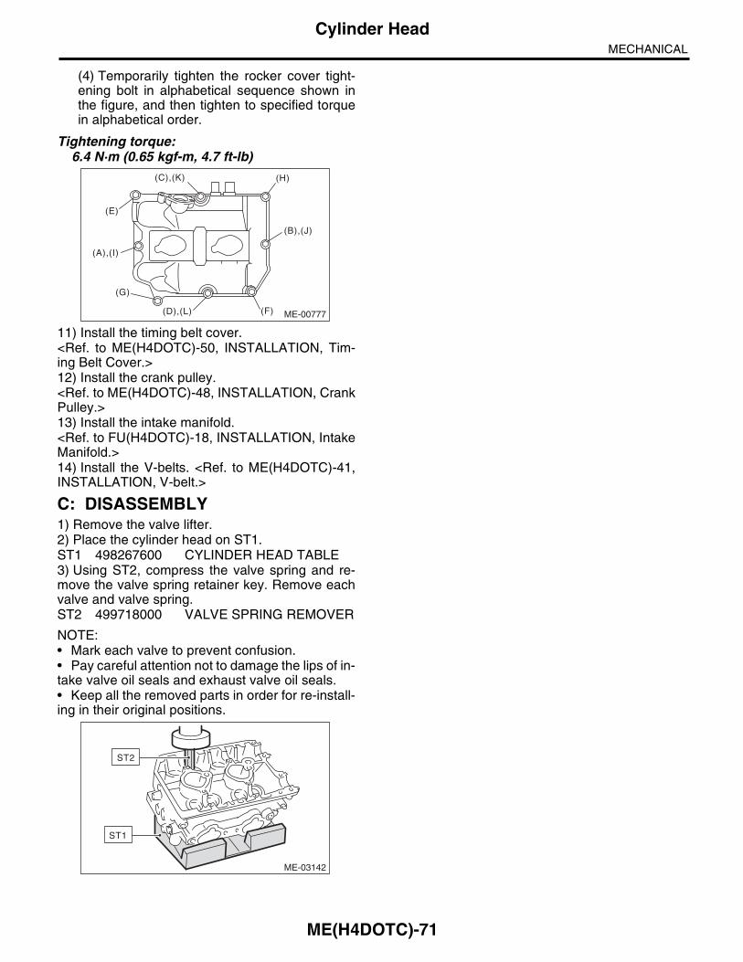
ME(H4DOTC)-71
Cylinder HeadMECHANICAL
(4) Temporarily tighten the rocker cover tight-ening bolt in alphabetical sequence shown inthe figure, and then tighten to specified torquein alphabetical order.
Tightening torque:6.4 N·m (0.65 kgf-m, 4.7 ft-lb)
11) Install the timing belt cover.<Ref. to ME(H4DOTC)-50, INSTALLATION, Tim-ing Belt Cover.>12) Install the crank pulley.<Ref. to ME(H4DOTC)-48, INSTALLATION, CrankPulley.>13) Install the intake manifold.<Ref. to FU(H4DOTC)-18, INSTALLATION, IntakeManifold.>14) Install the V-belts. <Ref. to ME(H4DOTC)-41,INSTALLATION, V-belt.>
C: DISASSEMBLY1) Remove the valve lifter.2) Place the cylinder head on ST1.ST1 498267600 CYLINDER HEAD TABLE3) Using ST2, compress the valve spring and re-move the valve spring retainer key. Remove eachvalve and valve spring.ST2 499718000 VALVE SPRING REMOVER
NOTE:• Mark each valve to prevent confusion.• Pay careful attention not to damage the lips of in-take valve oil seals and exhaust valve oil seals.• Keep all the removed parts in order for re-install-ing in their original positions.
ME-00777
(E)
(F)
(H)
(G)
(D),(L)
(A),(I)
(C),(K)
(B),(J)
ME-03142
ST1
ST2

ME(H4DOTC)-72
Cylinder HeadMECHANICAL
D: ASSEMBLY
(1) Exhaust valve (6) Valve spring (11) Intake valve guide
(2) Intake valve (7) Retainer (12) Exhaust valve guide
(3) Cylinder head (8) Retainer key (13) Plug
(4) Valve spring seat (9) Valve lifter
(5) Intake valve oil seal (10) Exhaust valve oil seal
ME-03157
(3)
(1)
(2)
(11) (4) (5) (6) (7) (8) (9)
(11)
(12)
(12)
(10)
(4)
(4)
(5) (6)
(6)
(7)
(7)
(8)
(8)
(9)
(9)(10)
(4)
(6)
(7)
(8)
(9)
(13)
(13)

ME(H4DOTC)-73
Cylinder HeadMECHANICAL
1) Install the valve spring and valve.(1) Coat the stem of each valve with engine oiland insert the valve into the valve guide.
NOTE:When inserting the valve into valve guide, use spe-cial care not to damage the oil seal lip.
(2) Set the cylinder head on ST1.ST1 498267600 CYLINDER HEAD TABLE
(3) Install the valve spring and retainer.
NOTE:Be sure to install the valve spring with its close-coiled end facing the seat on cylinder head.
(4) Set the ST2 on valve spring.ST2 499718000 VALVE SPRING REMOVER
(5) Compress the valve spring and fit the valvespring retainer key.(6) After installing, tap the valve spring retainerslightly with a plastic hammer for better seating.
2) Apply oil to the surfaces of the valve lifter.3) Install the valve lifter.
E: INSPECTION1. CYLINDER HEAD1) Check for cracks or damage. Use liquid pene-trant tester on the important sections to check forfissures. Check that there are no marks of gas leak-ing or water leaking on gasket installing surface.2) Measure the warping of the cylinder head sur-face that mates with cylinder block using a straightedge (A) and thickness gauge (B).If the warping exceeds the limit, correct the surfaceby grinding it with a surface grinder.
Warping limit:0.035 mm (0.0014 in)
Grinding limit:0.3 mm (0.012 in)
Standard height of cylinder head:127.5 mm (5.02 in)
NOTE:Uneven torque for the cylinder head bolts cancause warping. When reinstalling, pay special at-tention to the torque so as to tighten evenly.
ME-03142
ST1
ST2
ME-00126
(A)
(B)

ME(H4DOTC)-74
Cylinder HeadMECHANICAL
2. VALVE SEATInspect the intake and exhaust valve seats, andcorrect the contact surfaces with a valve seat cutterif they are defective or when valve guides are re-placed.
Valve seat width W:
StandardIntake
0.6 — 1.4 mm (0.024 — 0.055 in)Exhaust
1.2 — 1.8 mm (0.047 — 0.071 in)
3. VALVE GUIDE1) Check the clearance between valve guide andvalve stem. The clearance can be checked by mea-suring respectively the outer diameter of valvestem with a micrometer and the inner diameter ofvalve guide with a caliper gauge.
Clearance between the valve guide and valve stem:
StandardIntake
0.030 — 0.057 mm (0.0012 — 0.0022 in)Exhaust
0.040 — 0.067 mm (0.0016 — 0.0026 in)2) If the clearance between valve guide and valvestem exceeds the standard, replace the valveguide or valve itself whichever shows greateramount of wear or damaged and etc. See the fol-lowing procedure for valve guide replacement.
Valve guide inner diameter:6.000 — 6.012 mm (0.2362 — 0.2367 in)
Valve stem outer diameters:Intake
5.955 — 5.970 mm (0.2344 — 0.2350 in)Exhaust
5.945 — 5.960 mm (0.2341 — 0.2346 in)(1) Place the cylinder head on ST1 with thecombustion chamber upward so that valveguides fit the holes in ST1.(2) Insert the ST2 into valve guide and press itdown to remove the valve guide.
ST1 498267600 CYLINDER HEAD TABLEST2 499767200 VALVE GUIDE REMOVER
ME-00127
W
ME-00287
ME-00128
ST1
ST2

ME(H4DOTC)-75
Cylinder HeadMECHANICAL
(3) Turn the cylinder head upside down andplace the ST as shown in the figure.
ST 18251AA020 VALVE GUIDE ADJUSTER
(4) Before installing a new valve guide, makesure that neither scratches nor damages existon the inner surface of valve guide holes in cyl-inder head.(5) Put a new valve guide, coated with sufficientoil, in the cylinder head, and insert the ST1 intovalve guide. Press in until the valve guide upperend is flush with the upper surface of ST2.
ST1 499767200 VALVE GUIDE REMOVERST2 18251AA020 VALVE GUIDE ADJUSTER
(6) Check the valve guide protrusion.
Valve guide protrusion L:15.8 — 16.2 mm (0.622 — 0.638 in)(7) Ream the inside of valve guide using ST.Put the ST in valve guide, and rotate the STslowly clockwise while pushing it lightly. Bringthe ST back while rotating it clockwise.
NOTE:• Apply engine oil to the ST when reaming.• If the inner surface of valve guide is damaged,the edge of ST should be slightly ground with oilstone.• If the inner surface of valve guide becomes lus-trous and the ST does not chip, use a new ST orremedy the ST.ST 499767400 VALVE GUIDE REAMER
(8) After reaming, clean the valve guide to re-move chips.(9) Recheck the contact condition betweenvalve and valve seat after replacing the valveguide.
ST
L
ME-00757
ME-00130
ST1
ST2ME-00294

ME(H4DOTC)-76
Cylinder HeadMECHANICAL
4. INTAKE AND EXHAUST VALVE1) Inspect the flange and stem of valve, and re-place the valve with a new part if damaged, worn,deformed, or if dimension “H” in the figure is out-side of the specified limit.
Head edge thickness H:
StandardIntake (A)
1.0 — 1.4 mm (0.039 — 0.055 in)Exhaust (B)
1.3 — 1.7 mm (0.051 — 0.067 in)
2) Put a small amount of grinding compound on theseat surface, and lap the valve and seat surface.Replace with a new valve oil seal after lapping.
NOTE:It is possible to differentiate between the intakevalve and the exhaust valve by their overall length.
Valve overall length:Intake
104.4 mm (4.110 in)Exhaust
104.65 mm (4.1201 in)
5. VALVE SPRING1) Check the valve springs for damage, free length,and tension. Replace the valve spring if it is notwithin the standard value presented in the table.2) To measure the squareness of the valve spring,stand the spring on a surface plate and measure itsdeflection at the top of spring using a try square.
ME-00758
H
H
(B)
(A)
Free length mm (in) 47.32 (1.863)
Tension/spring heightN (kgf, lbf)/mm (in)
Set205 — 235 (20.9 — 24.0, 46.1 — 52.8)/36.0 (1.417)
Lift426 — 490 (43.4 — 50.0, 95.8 — 110)/26.50 (1.041)
Squareness2.5°, 2.1 mm (0.083 in) or less
ME-00283

ME(H4DOTC)-77
Cylinder HeadMECHANICAL
6. INTAKE AND EXHAUST VALVE OIL SEAL1) For the following, replace the oil seal with a newpart. See the procedure 2) and subsequent for re-placement procedures.• When the lip is damaged.• When the spring is out of the specified position.• When readjusting the surfaces of valve andvalve seat.• When replacing the valve guide.2) Place the cylinder head on ST1, and use ST2 topress-fit the oil seal.ST1 498267600 CYLINDER HEAD TABLEST2 498857100 VALVE OIL SEAL GUIDE
NOTE:• Apply engine oil to oil seal before press-fitting.• When press-fitting the oil seal, do not use a ham-mer, etc. or strike in.• The intake valve oil seals and exhaust valve oilseals are distinguished by their colors.
Color of rubber part:Intake [Gray]Exhaust [Green]
7. VALVE LIFTER1) Check the valve lifter visually.2) Measure the outer diameter of valve lifter.
Outer diameter:34.959 — 34.975 mm (1.3763 — 1.3770 in)
3) Measure the inner diameter of valve lifter matingsurface on cylinder head.
Inner diameter:34.994 — 35.016 mm (1.3777 — 1.3786 in)
NOTE:If difference between outer diameter of valve lifterand inner diameter of its mating surface is not with-in the standard or there is uneven wear, replace thecylinder head.
Standard:0.019 — 0.057 mm (0.0007 — 0.0022 in)
ME-00133
ST2
ME-00134
ME-00135

ME(H4DOTC)-78
Cylinder BlockMECHANICAL
20.Cylinder BlockA: REMOVALNOTE:Before conducting this procedure, drain the engineoil completely.1) Remove the V-belts. <Ref. to ME(H4DOTC)-41,REMOVAL, V-belt.>2) Remove the intake manifold.<Ref. to FU(H4DOTC)-15, REMOVAL, Intake Man-ifold.>3) Remove the crank pulley.<Ref. to ME(H4DOTC)-48, REMOVAL, Crank Pul-ley.>4) Remove the timing belt cover.<Ref. to ME(H4DOTC)-50, REMOVAL, Timing BeltCover.>5) Remove the timing belt.<Ref. to ME(H4DOTC)-51, REMOVAL, Timing Belt.>6) Remove the cam sprocket.<Ref. to ME(H4DOTC)-60, REMOVAL, Cam Sprock-et.>7) Remove the crank sprocket.<Ref. to ME(H4DOTC)-62, REMOVAL, Crank Sprock-et.>8) Remove the generator and A/C compressor withtheir brackets.9) Remove the camshaft.<Ref. to ME(H4DOTC)-63, REMOVAL, Camshaft.>10) Remove the cylinder head.<Ref. to ME(H4DOTC)-69, REMOVAL, CylinderHead.>11) Remove the clutch disc and cover. (MT model)<Ref. to CL-9, REMOVAL, Clutch Disc and Cover.>12) Remove the flywheel. (MT model)<Ref. to CL-12, REMOVAL, Flywheel.>13) Remove the drive plate. (AT model)Using the ST, lock the crankshaft.ST 498497100 CRANKSHAFT STOPPER
14) Remove the oil separator cover.15) Remove the water by-pass pipe for heater.16) Remove the oil filter. <Ref. to LU(H4DOTC)-19,REMOVAL, Engine Oil Filter.>
17) Remove the water pump. <Ref. to CO(H4DOTC)-15, REMOVAL, Water Pump.>18) Remove the bolts which install oil pump ontocylinder block.
NOTE:When disassembling and checking the oil pump,loosen the relief valve plug before removing the oilpump.
19) Remove the oil pump from cylinder block usinga flat tip screwdriver.
CAUTION:Be careful not to scratch the mating surface ofcylinder block and oil pump.
20) Remove the front oil seal from the oil pump.21) Remove the oil pan.
(1) Set the part so that the cylinder block LH ison the upper side.(2) Remove the bolts which secure oil pan tocylinder block.(3) Insert an oil pan cutter blade between cylin-der block-to-oil pan clearance and remove theoil pan.
CAUTION:Do not use a screwdriver or similar tools inplace of oil pan cutter.22) Remove the oil strainer.23) Remove the baffle plate.
ME-00136
ST
LU-00015
ME-00138
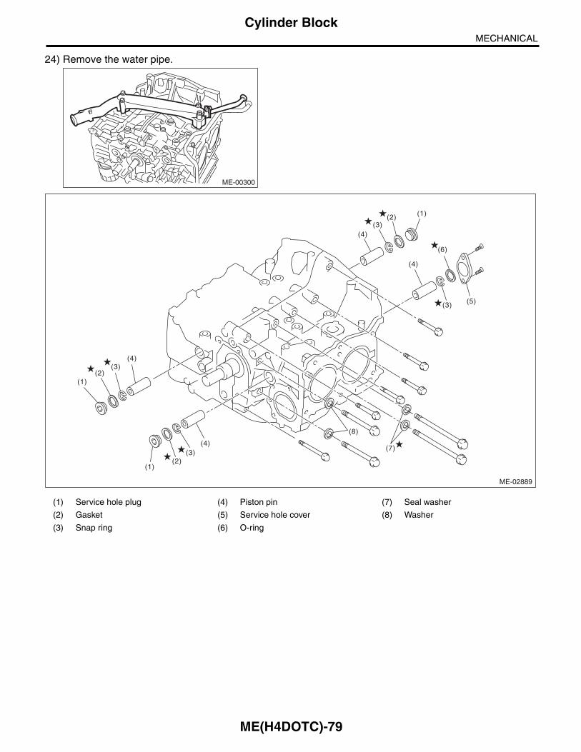
ME(H4DOTC)-79
Cylinder BlockMECHANICAL
24) Remove the water pipe.
ME-00300
(1) Service hole plug (4) Piston pin (7) Seal washer
(2) Gasket (5) Service hole cover (8) Washer
(3) Snap ring (6) O-ring
ME-02889
(3)
(4)
(2) (1)
(3)(4)
(5)
(6)
(2)(3)
(2)(1)
(3)(4)
(4)
(8)
(7)
(1)

ME(H4DOTC)-80
Cylinder BlockMECHANICAL
25) Remove the service hole plugs using a hexa-gon wrench [14 mm].
26) Remove the service hole cover.27) Rotate the crankshaft to bring #1 and #2 pis-tons to bottom dead center position, then removethe piston snap ring through service hole of #1 and#2 cylinders.
28) Draw out the piston pin from #1 and #2 pistonsusing ST.ST 499097700 PISTON PIN REMOVER
NOTE:Be careful not to confuse the original combinationof piston, piston pin and cylinder.
29) Similarly remove the piston pins from #3 and #4pistons.30) Remove the cylinder block connecting bolt onthe RH side.31) Loosen the cylinder block connecting bolt onthe LH side by 2-3 turns.32) Set the part so that the cylinder block LH is onthe upper side, and remove the cylinder block con-necting bolt.
ME-00140
ME-00141
ME-03325
ST

ME(H4DOTC)-81
Cylinder BlockMECHANICAL
33) Separate cylinder block LH and RH.
NOTE:When separating the cylinder block, do not allow the connecting rod to fall and damage the cylinder block.
34) Remove the rear oil seal.35) Remove the crankshaft together with connect-ing rod.36) Remove the crankshaft bearings from cylinderblock using a hammer handle.
NOTE:• Push the opposite side of the crank shaft bearinglocking lip to remove. • Be careful not to confuse the crankshaft bearingcombination.37) Draw out each piston from cylinder block usingwooden bar or hammer handle.
NOTE:Be careful not to confuse the original combinationof piston and cylinder.
(1) Cylinder block (4) Crankshaft bearing (7) Washer
(2) Rear oil seal (5) Piston
(3) Crankshaft (6) Seal washer
ME-02890
(2)
(3)
(4)
(4)
(5)
(6)
(5)
(1)
(1)
(7)
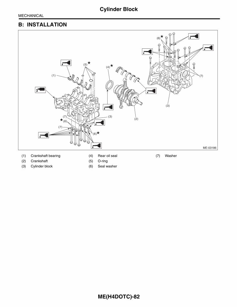
ME(H4DOTC)-82
Cylinder BlockMECHANICAL
B: INSTALLATION
(1) Crankshaft bearing (4) Rear oil seal (7) Washer
(2) Crankshaft (5) O-ring
(3) Cylinder block (6) Seal washer
ME-03186
(4)
(1)
(3)
(6)
(6)
(7)
(7)
(3)
(2)
(5)
(6)
(7)

ME(H4DOTC)-83
Cylinder BlockMECHANICAL
1) Remove oil on the mating surface of cylinderblock before installation. Apply a coat of engine oilto the bearing and crankshaft journal.2) Position the crankshaft and O-ring on cylinderblock RH.3) Apply liquid gasket to the mating surfaces of cyl-inder block RH, and position cylinder block LH.
NOTE:• Install within 5 min. after applying liquid gasket.• Do not allow liquid gasket to jut into O-ringgrooves, oil passages, bearing grooves, etc.
Liquid gasket:THREE BOND 1217G (Part No. K0877Y0100) or equivalent
4) Apply a coat of engine oil to the washer and boltthread.
NOTE:Use a new seal washer.5) Tighten the 10 mm cylinder block connectingbolts on LH side (A — D) in alphabetical sequence.
Tightening torque:10 N·m (1.0 kgf-m, 7.2 ft-lb)
6) Tighten the 10 mm cylinder block connectingbolts on RH side (E — J) in alphabetical sequence.
Tightening torque:10 N·m (1.0 kgf-m, 7.2 ft-lb)
7) Tighten the LH side cylinder block connectingbolts (A — D) further in alphabetical order.
Tightening torque:18 N·m (1.8 kgf-m, 13.3 ft-lb)
8) Tighten the RH side cylinder block connectingbolts (E — J) further in alphabetical order.
Tightening torque:18 N·m (1.8 kgf-m, 13.3 ft-lb)
ME-00145
ME-00779
(A)
(B)
(D)
(C)
ME-00780
(J)
(H)
(G)
(E)
(F)(I)
ME-00779
(A)
(B)
(D)
(C)
ME-00780
(J)
(H)
(G)
(E)
(F)(I)

ME(H4DOTC)-84
Cylinder BlockMECHANICAL
9) Tighten the LH side cylinder block connectingbolts (A — D) further in alphabetical order.• (A), (C): Angle tightening
Tightening angle:90°
• (B), (D): Torque tightening
Tightening torque:40 N·m (4.1 kgf-m, 29.5 ft-lb)
10) Tighten the RH side cylinder block connectingbolts (E — J) further in alphabetical order.
Tightening angle:90°
11) Tighten the 8 mm and 6 mm cylinder block con-necting bolts on the LH side (A — H) in alphabeticalorder.
Tightening torque:(A) — (G): 25 N·m (2.5 kgf-m, 18.4 ft-lb)(H): 6.4 N·m (0.65 kgf-m, 4.7 ft-lb)
12) Apply a coat of engine oil to the oil seal periph-ery, then install the rear oil seal using ST1 and ST2.
NOTE:Use a new rear oil seal.ST1 499597100 CRANKSHAFT OIL SEAL
GUIDEST2 499587200 CRANKSHAFT OIL SEAL
INSTALLER
13) Position the top ring gap at (A) or (B) in the fig-ure.14) Position the second ring gap at 180° on the re-verse side the top ring gap.
15) Position the upper rail gap at (C) in the figure.
ME-00779
(A)
(B)
(D)
(C)
ME-00780
(J)
(H)
(G)
(E)
(F)(I)
ME-00147
(B)(C)
(D)
(E)
(F)
(G)
(H)
(A)
(A) Rear oil seal
(B) Flywheel attaching bolt
ME-00148ST1
ST2
(B) (A)
ME-00718
(A) (B)
ME-02087
(C)
25

ME(H4DOTC)-85
Cylinder BlockMECHANICAL
16) Align the upper rail spin stopper (E) to the sidehole (D) on the piston.
17) Position the expander gap at (F) in the figure onthe 180° opposite direction of (C).
18) Set the lower rail gap at position (G), located120° clockwise from (C).
NOTE:• Make sure ring gaps do not face the same direc-tion.• Make sure ring gaps are not within the pistonskirt area.
ME-02471
(E)(D)
ME-02088
(F)
ME-02089120
(C)(G)

ME(H4DOTC)-86
Cylinder BlockMECHANICAL
19) Install the snap ring.Before positioning the piston on the cylinder block,attach the snap ring in the service hole of the cylin-der block, and the piston hole on the opposite side.
NOTE:Use new snap rings.
(A) Front side
ME-00306
#4
#3
#2
#1
(A)
(1) Piston (4) Gasket Tightening torque:N·m (kgf-m, ft-lb)
(2) Piston pin (5) Service hole plug T: 70 (7.1, 51.6)
(3) Snap ring
ME-02442
(1)
(1)
(2)(2)
(3)
(3)
(4)
(4)
(5)
(5)
T

ME(H4DOTC)-87
Cylinder BlockMECHANICAL
20) Install piston.(1) Set the parts so that the #1 and #2 cylindersare on the upper side.(2) Using the ST1, turn the crankshaft so that#1 and #2 connecting rods are set at bottomdead center.
ST1 499987500 CRANKSHAFT SOCKET(3) Apply a coat of engine oil to the pistons andcylinders and insert pistons in their cylinders us-ing ST2.
ST2 498747300 PISTON GUIDE
NOTE:Face the piston front mark towards the front of theengine.
21) Install piston pin.(1) Apply a coat of engine oil to ST3.(2) Insert ST3 into the service hole to align thepiston pin hole and the connecting rod smallend.
ST3 499017100 PISTON PIN GUIDE
(3) Apply a coat of engine oil to piston pin, andinsert the piston pin into piston and connectingrod through service hole.(4) Install the snap ring.
NOTE:Use new snap rings.
(5) Apply liquid gasket to the threaded portionof the service hole plug.
Liquid gasket:THREE BOND 1105 (Part No. 004403010) or equivalent
(A) Front mark
ME-00157
ST2
ST1
ME-00742
(A)
ME-00158
ST1 ST3
ME-00159
ME-00160
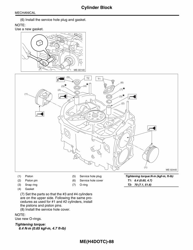
ME(H4DOTC)-88
Cylinder BlockMECHANICAL
(6) Install the service hole plug and gasket.
NOTE:Use a new gasket.
(7) Set the parts so that the #3 and #4 cylindersare on the upper side. Following the same pro-cedures as used for #1 and #2 cylinders, installthe pistons and piston pins.(8) Install the service hole cover.
NOTE:Use new O-rings.
Tightening torque:6.4 N·m (0.65 kgf-m, 4.7 ft-lb)
ME-00140
(1) Piston (5) Service hole plug Tightening torque:N·m (kgf-m, ft-lb)
(2) Piston pin (6) Service hole cover T1: 6.4 (0.65, 4.7)
(3) Snap ring (7) O-ring T2: 70 (7.1, 51.6)
(4) Gasket
(2)
(3)
(1)
(2)
(6)
(3)
(7)
(4)
(5)
ME-02440
T2 T1
(1)

ME(H4DOTC)-89
Cylinder BlockMECHANICAL
22) Install the water pipe.
NOTE:Use new O-rings.
Tightening torque: 6.4 N·m (0.65 kgf-m, 4.7 ft-lb)
23) Install the baffle plate.
Tightening torque:6.4 N·m (0.65 kgf-m, 4.7 ft-lb)
24) Install the oil strainer.
NOTE:Use new O-rings.
Tightening torque:10 N·m (1.0 kgf-m, 7.2 ft-lb)
25) Tighten the oil strainer stay together with thebaffle plate.
Tightening torque:6.4 N·m (0.65 kgf-m, 4.7 ft-lb)
26) Apply liquid gasket to the mating surfaces of oilpan, and install the oil pan.
NOTE:Install within 5 min. after applying liquid gasket.
Liquid gasket:THREE BOND 1217G (Part No. K0877Y0100) or equivalent
Tightening torque:5 N·m (0.5 kgf-m, 3.7 ft-lb)
27) Apply liquid gasket to the mating surface of oilseparator cover and the threaded portion of bolt (A)shown in the figure (when reusing the bolt), andthen install the oil separator cover.
NOTE:• Install within 5 min. after applying liquid gasket.• Use new oil separator cover.
Liquid gasket:Mating surface
THREE BOND 1217G (Part No. K0877Y0100) or equivalent
Bolt thread (A) (when reusing the bolt)THREE BOND 1324 (Part No. 004403042) or equivalent
Tightening torque:6.4 N·m (0.65 kgf-m, 4.7 ft-lb)
28) Install the drive plate. (AT model)Using the ST, lock the crankshaft.ST 498497100 CRANKSHAFT STOPPER
Tightening torque:72 N·m (7.3 kgf-m, 53.1 ft-lb)
29) Install the flywheel. (MT model) <Ref. to CL-12,INSTALLATION, Flywheel.>30) Install the clutch disc and cover. (MT model)<Ref. to CL-9, INSTALLATION, Clutch Disc andCover.>
(A) Gasket
ME-00300
LU-02353
(A)
ME-03333
(A)
ME-00136
ST

ME(H4DOTC)-90
Cylinder BlockMECHANICAL
31) Install the oil pump.(1) Using the ST, install the front oil seal.
ST 499587100 OIL SEAL INSTALLER
NOTE:Use a new front oil seal.
(2) Apply liquid gasket to the matching surfaceof oil pump.
NOTE:Install within 5 min. after applying liquid gasket.
Liquid gasket:THREE BOND 1217G (Part No. K0877Y0100) or equivalent
(3) Apply a coat of engine oil to the inside of oilseal.
(4) Install the oil pump to cylinder block. Becareful not to damage the oil seal during instal-lation.
NOTE:• Make sure the oil seal lip is not folded.• Align the flat surface of oil pump’s inner rotor withcrankshaft before installation.• Use new O-rings and oil seals.• Do not forget to install the O-ring.
(5) Apply liquid gasket to the three bolts threadshown in figure. (when reusing bolts)
Liquid gasket:THREE BOND 1324 (Part No. 004403042) or equivalent
Tightening torque:6.4 N·m (0.65 kgf-m, 4.7 ft-lb)
32) Install the service hole plug and gasket.
NOTE:• When installing the water pump, tighten bolts intwo stages in alphabetical sequence as shown inthe figure.• Use a new gasket.
Tightening torque:First: 12 N·m (1.2 kgf-m, 8.9 ft-lb)Second: 12 N·m (1.2 kgf-m, 8.9 ft-lb)
33) Install the water by-pass pipe for heater.
Tightening torque: 6.4 N·m (0.65 kgf-m, 4.7 ft-lb)
34) Install the oil filter. <Ref. to LU(H4DOTC)-19,INSTALLATION, Engine Oil Filter.>
(A) O-ring
LU-00021
ST
ME-00165
(A)
ME-00312
LU-02103T
ME-02463
(F)(E)
(D)
(C)
(B)
(A)

ME(H4DOTC)-91
Cylinder BlockMECHANICAL
35) Install the cylinder head.<Ref. to ME(H4DOTC)-70, INSTALLATION, Cylin-der Head.>36) Install the camshaft. <Ref. to ME(H4DOTC)-64, INSTALLATION, Camshaft.>37) Install the generator and A/C compressor withtheir brackets.
Tightening torque: 36 N·m (3.7 kgf-m, 26.6 ft-lb)
38) Install the crank sprocket. <Ref. to ME(H4DOTC)-62, INSTALLATION, Crank Sprocket.>39) Install the cam sprocket.<Ref. to ME(H4DOTC)-60, INSTALLATION, CamSprocket.>40) Install the timing belt.<Ref. to ME(H4DOTC)-53, INSTALLATION, Tim-ing Belt.>41) Adjust the valve clearance. <Ref. toME(H4DOTC)-28, ADJUSTMENT, Valve Clearance.>42) Install the rocker cover.
(1) Install the rocker cover gasket to the rockercover.
NOTE:Use a new rocker cover gasket.
(2) Apply liquid gasket to the specified point ofthe cylinder head. Apply extra amount of liquidgasket around semicircular plugs 5 mm or more.
NOTE:Install within 5 min. after applying liquid gasket.
Liquid gasket:THREE BOND 1217G (Part No. K0877Y0100) or equivalent
(3) Install the rocker cover on cylinder head.Ensure the gasket is properly positioned duringinstallation.(4) Temporarily tighten the rocker cover tight-ening bolt in alphabetical sequence shown inthe figure, and then tighten to specified torquein alphabetical order.
Tightening torque:6.4 N·m (0.65 kgf-m, 4.7 ft-lb)
43) Install the timing belt cover.<Ref. to ME(H4DOTC)-50, INSTALLATION, Tim-ing Belt Cover.>44) Install the crank pulley.<Ref. to ME(H4DOTC)-48, INSTALLATION, CrankPulley.>45) Install the intake manifold.<Ref. to FU(H4DOTC)-18, INSTALLATION, IntakeManifold.>46) Install the V-belts. <Ref. to ME(H4DOTC)-41,INSTALLATION, V-belt.>
ME-02771
ME-00777
(E)
(F)
(H)
(G)
(D),(L)
(A),(I)
(C),(K)
(B),(J)

ME(H4DOTC)-92
Cylinder BlockMECHANICAL
C: DISASSEMBLY
1) Remove the connecting rod cap.2) Remove the connecting rod bearing.
NOTE:Keep the removed connecting rods, connecting rodcaps and bearings in order so that they are kept intheir original combinations/groups, and not mixedtogether.3) Remove the piston rings using piston ring ex-pander.4) Remove the oil ring by hand.
NOTE:Arrange the removed piston rings in proper order,to prevent confusion.5) Remove the snap ring.
(1) Connecting rod cap (4) Second ring (6) Snap ring
(2) Connecting rod bearing (5) Oil ring (7) Connecting rod
(3) Top ring
ME-03556
(2)
(2)
(6)
(5)(4)
(3)
(1)
(7)

ME(H4DOTC)-93
Cylinder BlockMECHANICAL
D: ASSEMBLY
1) Apply engine oil to the surface of the connectingrod bearings, and install to connecting rods andconnecting rod caps.2) Position each connecting rod with their sidemarks facing forward, and install.3) Attach the connecting rod cap, and tighten withthe connecting rod bolt. Make sure the arrow markon connecting rod cap facing front during installa-tion.
NOTE:• Each connecting rod has its own mating cap.Make sure that they are assembled correctly bychecking their matching number.• When tightening the connecting rod bolts, applyoil on the threads.
Tightening torque:52 N·m (5.3 kgf-m, 38.4 ft-lb)
4) Install the oil ring upper rail, expander and lowerrail by hand.5) Install the second ring and top ring using pistonring expander.
NOTE:Assemble so that the piston ring mark “R” faces thetop side of the piston.
(1) Connecting rod bearing (5) Second ring Tightening torque:N·m (kgf-m, ft-lb)
(2) Connecting rod (6) Top ring T: 52 (5.3, 38.4)
(3) Connecting rod cap (7) Snap ring
(4) Oil ring (8) Side mark
ME-02985
(1)
(1)
(7)
(4)(5)
(6)
(3)T
(2)
(8)

ME(H4DOTC)-94
Cylinder BlockMECHANICAL
E: INSPECTION1. CYLINDER BLOCK1) Check for cracks or damage. Use liquid pene-trant tester on the important sections to check forfissures. Check that there are no marks of gas leak-ing or water leaking on gasket installing surface.2) Check the oil passages for clogging.3) Inspect the cylinder block surface that mateswith cylinder head for warping by using a straightedge, and correct by grinding if necessary.
Warping limit:0.025 mm (0.00098 in)
Grinding limit:0.1 mm (0.004 in)
Standard height of cylinder block:201.0 mm (7.91 in)
2. CYLINDER AND PISTON1) The cylinder bore size is stamped on the frontupper face of the cylinder block.
NOTE:• Measurement should be performed at a temper-ature of 20°C (68°F).• Standard sized pistons are classified into twogrades, “A” and “B”. These grades should be usedas guide lines in selecting a standard piston.
Standard diameter:A: 99.505 — 99.515 mm (3.9175 — 3.9179 in)B: 99.495 — 99.505 mm (3.9171 — 3.9175 in)
(A) Main journal size mark
(B) Cylinder block RH – LH combination mark
(C) #1 cylinder bore size mark
(D) #2 cylinder bore size mark
(E) #3 cylinder bore size mark
(F) #4 cylinder bore size mark
ME-00170
#5
#4
#3
#2
#1
(A) (B)
(F)
(D)A
B
AB
54
54
(C)(E)
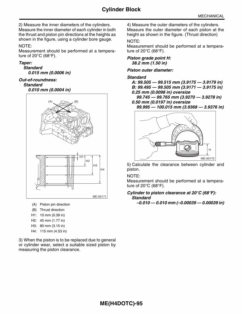
ME(H4DOTC)-95
Cylinder BlockMECHANICAL
2) Measure the inner diameters of the cylinders.Measure the inner diameter of each cylinder in boththe thrust and piston pin directions at the heights asshown in the figure, using a cylinder bore gauge.
NOTE:Measurement should be performed at a tempera-ture of 20°C (68°F).
Taper:Standard
0.015 mm (0.0006 in)
Out-of-roundness:Standard
0.010 mm (0.0004 in)
3) When the piston is to be replaced due to generalor cylinder wear, select a suitable sized piston bymeasuring the piston clearance.
4) Measure the outer diameters of the cylinders.Measure the outer diameter of each piston at theheight as shown in the figure. (Thrust direction)
NOTE:Measurement should be performed at a tempera-ture of 20°C (68°F).
Piston grade point H:38.2 mm (1.50 in)
Piston outer diameter:
StandardA: 99.505 — 99.515 mm (3.9175 — 3.9179 in)B: 99.495 — 99.505 mm (3.9171 — 3.9175 in)0.25 mm (0.0098 in) oversize
99.745 — 99.765 mm (3.9270 — 3.9278 in)0.50 mm (0.0197 in) oversize
99.995 — 100.015 mm (3.9368 — 3.9376 in)
5) Calculate the clearance between cylinder andpiston.
NOTE:Measurement should be performed at a tempera-ture of 20°C (68°F).
Cylinder to piston clearance at 20°C (68°F):Standard
–0.010 — 0.010 mm (–0.00039 — 0.00039 in)(A) Piston pin direction
(B) Thrust direction
H1: 10 mm (0.39 in)
H2: 45 mm (1.77 in)
H3: 80 mm (3.15 in)
H4: 115 mm (4.53 in)
ME-00171
(A) (B)
H2H1
H3H4
ME-00172
H
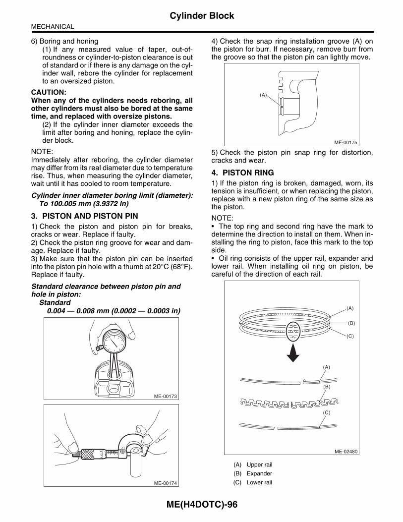
ME(H4DOTC)-96
Cylinder BlockMECHANICAL
6) Boring and honing(1) If any measured value of taper, out-of-roundness or cylinder-to-piston clearance is outof standard or if there is any damage on the cyl-inder wall, rebore the cylinder for replacementto an oversized piston.
CAUTION:When any of the cylinders needs reboring, allother cylinders must also be bored at the sametime, and replaced with oversize pistons.
(2) If the cylinder inner diameter exceeds thelimit after boring and honing, replace the cylin-der block.
NOTE:Immediately after reboring, the cylinder diametermay differ from its real diameter due to temperaturerise. Thus, when measuring the cylinder diameter,wait until it has cooled to room temperature.
Cylinder inner diameter boring limit (diameter):To 100.005 mm (3.9372 in)
3. PISTON AND PISTON PIN1) Check the piston and piston pin for breaks,cracks or wear. Replace if faulty.2) Check the piston ring groove for wear and dam-age. Replace if faulty.3) Make sure that the piston pin can be insertedinto the piston pin hole with a thumb at 20°C (68°F).Replace if faulty.
Standard clearance between piston pin and hole in piston:
Standard0.004 — 0.008 mm (0.0002 — 0.0003 in)
4) Check the snap ring installation groove (A) onthe piston for burr. If necessary, remove burr fromthe groove so that the piston pin can lightly move.
5) Check the piston pin snap ring for distortion,cracks and wear.
4. PISTON RING1) If the piston ring is broken, damaged, worn, itstension is insufficient, or when replacing the piston,replace with a new piston ring of the same size asthe piston.
NOTE:• The top ring and second ring have the mark todetermine the direction to install on them. When in-stalling the ring to piston, face this mark to the topside.• Oil ring consists of the upper rail, expander andlower rail. When installing oil ring on piston, becareful of the direction of each rail.
ME-00173
ME-00174
(A) Upper rail
(B) Expander
(C) Lower rail
ME-00175
(A)
ME-02480
(A)
(B)
(C)
(A)
(B)
(C)

ME(H4DOTC)-97
Cylinder BlockMECHANICAL
2) Squarely place the piston ring and oil ring in cyl-inder using the piston, and measure the piston ringgap with a thickness gauge.
3) Fit the piston ring straight into the piston ringgroove, then measure the clearance between pis-ton ring and piston ring groove with a thicknessgauge.
NOTE:Before measuring the clearance, clean the pistonring groove and piston ring.
5. CONNECTING ROD1) Replace the connecting rod, if the large or smallend thrust surface is damaged.2) Check for bend or twist using a connecting rodaligner. Replace the connecting rod if the bend ortwist exceeds the limit.
Limit of bend or twist per 100 mm (3.94 in) in length:
0.10 mm (0.0039 in)
3) Install the connecting rod fitted with bearing tothe crankshaft, and measure the thrust clearanceusing a thickness gauge. If the thrust clearance ex-ceeds the standard or uneven wear is found, re-place the connecting rod.
Connecting rod thrust clearance:Standard
0.070 — 0.330 mm (0.0028 — 0.0130 in)
Standardmm (in)
Piston ring gap
Top ring0.20 — 0.25
(0.0079 — 0.0098)
Second ring0.37 — 0.52
(0.015 — 0.020)
Oil ring rail0.20 — 0.50
(0.0079 — 0.0197)
Standardmm (in)
Clearance between piston ring and pis-ton ring groove
Top ring0.040 — 0.080
(0.0016 — 0.0031)
Second ring0.030 — 0.070
(0.0012 — 0.0028)
ME-00177
ME-00178
(A) Thickness gauge
(B) Connecting rod
( A )
( A )
( B )
( B )
ME-00179
ME-00180
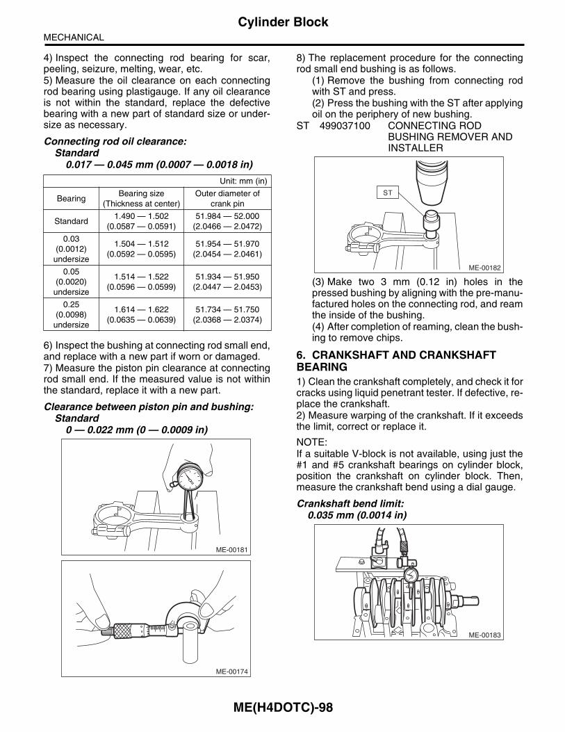
ME(H4DOTC)-98
Cylinder BlockMECHANICAL
4) Inspect the connecting rod bearing for scar,peeling, seizure, melting, wear, etc.5) Measure the oil clearance on each connectingrod bearing using plastigauge. If any oil clearanceis not within the standard, replace the defectivebearing with a new part of standard size or under-size as necessary.
Connecting rod oil clearance:Standard
0.017 — 0.045 mm (0.0007 — 0.0018 in)
6) Inspect the bushing at connecting rod small end,and replace with a new part if worn or damaged.7) Measure the piston pin clearance at connectingrod small end. If the measured value is not withinthe standard, replace it with a new part.
Clearance between piston pin and bushing:Standard
0 — 0.022 mm (0 — 0.0009 in)
8) The replacement procedure for the connectingrod small end bushing is as follows.
(1) Remove the bushing from connecting rodwith ST and press.(2) Press the bushing with the ST after applyingoil on the periphery of new bushing.
ST 499037100 CONNECTING ROD BUSHING REMOVER AND INSTALLER
(3) Make two 3 mm (0.12 in) holes in thepressed bushing by aligning with the pre-manu-factured holes on the connecting rod, and reamthe inside of the bushing.(4) After completion of reaming, clean the bush-ing to remove chips.
6. CRANKSHAFT AND CRANKSHAFT BEARING1) Clean the crankshaft completely, and check it forcracks using liquid penetrant tester. If defective, re-place the crankshaft.2) Measure warping of the crankshaft. If it exceedsthe limit, correct or replace it.
NOTE:If a suitable V-block is not available, using just the#1 and #5 crankshaft bearings on cylinder block,position the crankshaft on cylinder block. Then,measure the crankshaft bend using a dial gauge.
Crankshaft bend limit:0.035 mm (0.0014 in)
Unit: mm (in)
BearingBearing size
(Thickness at center)Outer diameter of
crank pin
Standard1.490 — 1.502
(0.0587 — 0.0591)51.984 — 52.000
(2.0466 — 2.0472)
0.03 (0.0012)
undersize
1.504 — 1.512(0.0592 — 0.0595)
51.954 — 51.970(2.0454 — 2.0461)
0.05 (0.0020)
undersize
1.514 — 1.522(0.0596 — 0.0599)
51.934 — 51.950(2.0447 — 2.0453)
0.25 (0.0098)
undersize
1.614 — 1.622(0.0635 — 0.0639)
51.734 — 51.750(2.0368 — 2.0374)
ME-00181
ME-00174
ME-00182
ST
ME-00183
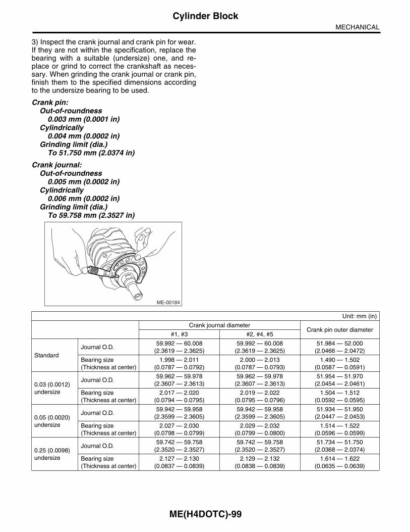
ME(H4DOTC)-99
Cylinder BlockMECHANICAL
3) Inspect the crank journal and crank pin for wear.If they are not within the specification, replace thebearing with a suitable (undersize) one, and re-place or grind to correct the crankshaft as neces-sary. When grinding the crank journal or crank pin,finish them to the specified dimensions accordingto the undersize bearing to be used.
Crank pin:Out-of-roundness
0.003 mm (0.0001 in)Cylindrically
0.004 mm (0.0002 in)Grinding limit (dia.)
To 51.750 mm (2.0374 in)
Crank journal:Out-of-roundness
0.005 mm (0.0002 in)Cylindrically
0.006 mm (0.0002 in)Grinding limit (dia.)
To 59.758 mm (2.3527 in)
ME-00184
Unit: mm (in)
Crank journal diameterCrank pin outer diameter
#1, #3 #2, #4, #5
StandardJournal O.D.
59.992 — 60.008(2.3619 — 2.3625)
59.992 — 60.008(2.3619 — 2.3625)
51.984 — 52.000(2.0466 — 2.0472)
Bearing size(Thickness at center)
1.998 — 2.011(0.0787 — 0.0792)
2.000 — 2.013(0.0787 — 0.0793)
1.490 — 1.502(0.0587 — 0.0591)
0.03 (0.0012)undersize
Journal O.D.59.962 — 59.978
(2.3607 — 2.3613)59.962 — 59.978
(2.3607 — 2.3613)51.954 — 51.970
(2.0454 — 2.0461)
Bearing size(Thickness at center)
2.017 — 2.020(0.0794 — 0.0795)
2.019 — 2.022(0.0795 — 0.0796)
1.504 — 1.512(0.0592 — 0.0595)
0.05 (0.0020)undersize
Journal O.D.59.942 — 59.958
(2.3599 — 2.3605)59.942 — 59.958
(2.3599 — 2.3605)51.934 — 51.950
(2.0447 — 2.0453)
Bearing size(Thickness at center)
2.027 — 2.030(0.0798 — 0.0799)
2.029 — 2.032(0.0799 — 0.0800)
1.514 — 1.522(0.0596 — 0.0599)
0.25 (0.0098)undersize
Journal O.D.59.742 — 59.758
(2.3520 — 2.3527)59.742 — 59.758
(2.3520 — 2.3527)51.734 — 51.750
(2.0368 — 2.0374)
Bearing size(Thickness at center)
2.127 — 2.130(0.0837 — 0.0839)
2.129 — 2.132(0.0838 — 0.0839)
1.614 — 1.622(0.0635 — 0.0639)

ME(H4DOTC)-100
Cylinder BlockMECHANICAL
4) Use a thickness gauge to measure the thrustclearance of the crankshaft at the #5 crank journalbearing. If clearance exceeds the standard, replacethe bearing.
Crankshaft thrust clearance:Standard
0.030 — 0.115 mm (0.0012 — 0.0045 in)
5) Inspect individual crankshaft bearings for signsof flaking, seizure, melting and wear.6) Measure the oil clearance on each crankshaftbearing using plastigauge. If the measured value isout of standard, replace the defective bearing withan undersize one, and replace or grind to correctthe crankshaft as necessary.
Crankshaft oil clearance:Standard
0.010 — 0.030 mm (0.0004 — 0.0012 in)
ME-00322

ME(H4DOTC)-101
Intake and Exhaust ValveMECHANICAL
21.Intake and Exhaust ValveA: SPECIFICATIONRefer to “Cylinder Head” for removal and installa-tion procedures of intake and exhaust valves. <Ref.to ME(H4DOTC)-69, REMOVAL, Cylinder Head.><Ref. to ME(H4DOTC)-70, INSTALLATION, Cylin-der Head.>

ME(H4DOTC)-102
PistonMECHANICAL
22.PistonA: SPECIFICATIONRefer to “Cylinder Block” for removal and installationprocedures of pistons. <Ref. to ME(H4DOTC)-78,REMOVAL, Cylinder Block.> <Ref. to ME(H4DOTC)-82, INSTALLATION, Cylinder Block.>

ME(H4DOTC)-103
Connecting RodMECHANICAL
23.Connecting RodA: SPECIFICATIONRefer to “Cylinder Block” for removal and installa-tion procedures of connecting rod.<Ref. to ME(H4DOTC)-78, REMOVAL, CylinderBlock.> <Ref. to ME(H4DOTC)-82, INSTALLA-TION, Cylinder Block.>

ME(H4DOTC)-104
CrankshaftMECHANICAL
24.CrankshaftA: SPECIFICATIONRefer to “Cylinder Block” for removal and installa-tion procedures of the crankshaft. <Ref. toME(H4DOTC)-78, REMOVAL, Cylinder Block.><Ref. to ME(H4DOTC)-82, INSTALLATION, Cylin-der Block.>

ME(H4DOTC)-105
Engine Trouble in GeneralMECHANICAL
25.Engine Trouble in GeneralA: INSPECTIONNOTE:The “RANK” shown in the chart shows the possibilities of the cause of trouble in order from “Very often” to“Rarely”.A — Very oftenB — SometimesC — Rarely
Symptom Problem parts etc. Possible cause RANK
1. Engine does not start.
1) Starter does not turn. Starter Defective battery-to-starter harness B
Defective starter switch C
Defective inhibitor switch or neutral switch C
Defective starter B
Battery Improper connection of terminal A
Run-down battery A
Defective charging system B
Friction Seizure of crankshaft and connecting rod bearing C
Seized camshaft C
Seized or stuck piston and cylinder C
2) Initial combustion does not occur.
Starter Defective starter C
Engine control system <Ref. to EN(H4DOTC)(diag)-2, Basic Diagnostic Procedure.> A
Fuel line Defective fuel pump and relay A
Clogged fuel line C
Lack of or insufficient fuel B
Timing belt Degradation, etc. B
Defective timing B
Compression Incorrect valve clearance C
Loosened spark plug or defective gasket C
Loosened cylinder head bolt or defective gasket C
Improper valve sealing C
Defective valve stem C
Worn or broken valve spring B
Worn or stuck piston rings, cylinder and piston C
Incorrect valve timing B
Improper engine oil (low viscosity) B

ME(H4DOTC)-106
Engine Trouble in GeneralMECHANICAL
3) Initial combustion occurs. Engine control system <Ref. to EN(H4DOTC)(diag)-2, Basic Diagnostic Procedure.> A
Intake system Defective intake manifold gasket B
Defective throttle body gasket B
Fuel line Defective fuel pump and relay C
Clogged fuel line C
Lack of or insufficient fuel B
Timing belt Degradation, etc. B
Defective timing B
Compression Incorrect valve clearance C
Loosened spark plug or defective gasket C
Loosened cylinder head bolt or defective gasket C
Improper valve sealing C
Defective valve stem C
Worn or broken valve spring B
Worn or stuck piston rings, cylinder and piston C
Incorrect valve timing B
Improper engine oil (low viscosity) B
4) Engine stalls after initial combustion.
Engine control system <Ref. to EN(H4DOTC)(diag)-2, Basic Diagnostic Procedure.> A
Intake system Loosened or cracked intake duct B
Loosened or cracked PCV hose C
Loosened or cracked vacuum hose C
Defective intake manifold gasket B
Defective throttle body gasket B
Dirty air cleaner element C
Fuel line Clogged fuel line C
Lack of or insufficient fuel B
Timing belt Degradation, etc. B
Defective timing B
Compression Incorrect valve clearance C
Loosened spark plug or defective gasket C
Loosened cylinder head bolt or defective gasket C
Improper valve sealing C
Defective valve stem C
Worn or broken valve spring B
Worn or stuck piston rings, cylinder and piston C
Incorrect valve timing B
Improper engine oil (low viscosity) B
Symptom Problem parts etc. Possible cause RANK

ME(H4DOTC)-107
Engine Trouble in GeneralMECHANICAL
2. Rough idle and engine stall
Engine control system <Ref. to EN(H4DOTC)(diag)-2, Basic Diagnostic Procedure.> A
Intake system Loosened or cracked intake duct A
Loosened or cracked PCV hose A
Loosened or cracked vacuum hose A
Defective intake manifold gasket B
Defective throttle body gasket B
Defective PCV valve C
Loosened oil filler cap B
Dirty air cleaner element C
Fuel line Defective fuel pump and relay C
Clogged fuel line C
Lack of or insufficient fuel B
Timing belt Defective timing C
Compression Incorrect valve clearance B
Loosened spark plug or defective gasket B
Loosened cylinder head bolt or defective gasket B
Improper valve sealing B
Defective valve stem C
Worn or broken valve spring B
Worn or stuck piston rings, cylinder and piston B
Incorrect valve timing A
Improper engine oil (low viscosity) B
Lubrication system Incorrect oil pressure B
Defective rocker cover gasket C
Cooling system Overheating C
Others Evaporative emission control system malfunction A
Stuck or damaged throttle valve B
Symptom Problem parts etc. Possible cause RANK

ME(H4DOTC)-108
Engine Trouble in GeneralMECHANICAL
3. Low output, hesitation and poor acceleration
Engine control system <Ref. to EN(H4DOTC)(diag)-2, Basic Diagnostic Procedure.> A
Intake system Loosened or cracked intake duct A
Loosened or cracked PCV hose A
Loosened or cracked vacuum hose B
Defective intake manifold gasket B
Defective throttle body gasket B
Defective PCV valve B
Loosened oil filler cap B
Dirty air cleaner element A
Fuel line Defective fuel pump and relay B
Clogged fuel line B
Lack of or insufficient fuel C
Timing belt Defective timing B
Compression Incorrect valve clearance B
Loosened spark plug or defective gasket B
Loosened cylinder head bolt or defective gasket B
Improper valve sealing B
Defective valve stem C
Worn or broken valve spring B
Worn or stuck piston rings, cylinder and piston C
Incorrect valve timing A
Improper engine oil (low viscosity) B
Lubrication system Incorrect oil pressure B
Cooling system Overheating C
Over-cooling C
Others Evaporative emission control system malfunction A
4. Surging Engine control system <Ref. to EN(H4DOTC)(diag)-2, Basic Diagnostic Procedure.> A
Intake system Loosened or cracked intake duct A
Loosened or cracked PCV hose A
Loosened or cracked vacuum hose A
Defective intake manifold gasket B
Defective throttle body gasket B
Defective PCV valve B
Loosened oil filler cap B
Dirty air cleaner element B
Fuel line Defective fuel pump and relay B
Clogged fuel line B
Lack of or insufficient fuel C
Timing belt Defective timing B
Compression Incorrect valve clearance B
Loosened spark plug or defective gasket C
Loosened cylinder head bolt or defective gasket C
Improper valve sealing C
Defective valve stem C
Worn or broken valve spring C
Worn or stuck piston rings, cylinder and piston C
Incorrect valve timing A
Improper engine oil (low viscosity) B
Cooling system Overheating B
Others Evaporative emission control system malfunction C
Symptom Problem parts etc. Possible cause RANK

ME(H4DOTC)-109
Engine Trouble in GeneralMECHANICAL
5. Engine does not return to idle.
Engine control system <Ref. to EN(H4DOTC)(diag)-2, Basic Diagnostic Procedure.> A
Intake system Loosened or cracked vacuum hose A
Others Stuck or damaged throttle valve A
6. Dieseling (Run-on) Engine control system <Ref. to EN(H4DOTC)(diag)-2, Basic Diagnostic Procedure.> A
Cooling system Overheating B
Others Evaporative emission control system malfunction B
7. After burning in exhaust system
Engine control system <Ref. to EN(H4DOTC)(diag)-2, Basic Diagnostic Procedure.> A
Intake system Loosened or cracked intake duct C
Loosened or cracked PCV hose C
Loosened or cracked vacuum hose B
Defective PCV valve B
Loosened oil filler cap C
Timing belt Defective timing B
Compression Incorrect valve clearance B
Loosened spark plug or defective gasket C
Loosened cylinder head bolt or defective gasket C
Improper valve sealing B
Defective valve stem C
Worn or broken valve spring C
Worn or stuck piston rings, cylinder and piston C
Incorrect valve timing A
Lubrication system Incorrect oil pressure C
Cooling system Over-cooling C
Others Evaporative emission control system malfunction C
8. Knocking Engine control system <Ref. to EN(H4DOTC)(diag)-2, Basic Diagnostic Procedure.> A
Intake system Loosened oil filler cap B
Timing belt Defective timing B
Compression Incorrect valve clearance C
Incorrect valve timing B
Cooling system Overheating A
9. Excessive engine oil con-sumption
Intake system Loosened or cracked PCV hose A
Defective PCV valve B
Loosened oil filler cap C
Compression Defective valve stem A
Worn or stuck piston rings, cylinder and piston A
Lubrication system Loosened oil pump attaching bolts and defective gas-ket
B
Defective oil filter gasket B
Defective crankshaft oil seal B
Defective rocker cover gasket B
Loosened oil drain plug or defective gasket B
Loosened oil pan fitting bolts or defective oil pan B
Symptom Problem parts etc. Possible cause RANK

ME(H4DOTC)-110
Engine Trouble in GeneralMECHANICAL
10. Excessive fuel consump-tion
Engine control system <Ref. to EN(H4DOTC)(diag)-2, Basic Diagnostic Procedure.> A
Intake system Dirty air cleaner element A
Timing belt Defective timing B
Compression Incorrect valve clearance B
Loosened spark plug or defective gasket C
Loosened cylinder head bolt or defective gasket C
Improper valve sealing B
Defective valve stem C
Worn or broken valve spring C
Worn or stuck piston rings, cylinder and piston B
Incorrect valve timing B
Lubrication system Incorrect oil pressure C
Cooling system Over-cooling C
Symptom Problem parts etc. Possible cause RANK

ME(H4DOTC)-111
Engine NoiseMECHANICAL
26.Engine NoiseA: INSPECTION
NOTE*)When disconnecting the fuel injector connector, the malfunction indicator light illuminates and DTC is stored in ECM memory.Therefore, after connecting the fuel injector connector, execute Clear Memory Mode <Ref. to EN(H4DOTC)(diag)-55, OPERA-TION, Clear Memory Mode.> and Inspection Mode <Ref. to EN(H4DOTC)(diag)-44, PROCEDURE, Inspection Mode.>.
Type of sound Condition Possible cause
Regular clicking soundSound increases as engine speed increases.
• Valve mechanism is defective.• Incorrect valve clearance• Worn camshaft• Broken valve spring
Heavy and dull clankOil pressure is low.
• Worn crankshaft main bearing• Worn connecting rod bearing (large end)
Oil pressure is normal.• Loosened flywheel mounting bolt• Damaged engine mounting
High-pitched clankSound is noticeable when accelerating with an overload condition.
• Ignition timing advanced• Accumulation of carbon inside combustion chamber• Wrong heat-durability spark plug• Improper octane value gasoline
Clank when engine speed is between 1,000 and 2,000 rpm.
Sound is reduced when fuel injector connector of noisy cyl-inder is disconnected. (NOTE*)
• Worn crankshaft main bearing• Worn connecting rod bearing (large end)
Knocking sound when engine is operating under idling speed and engine is warm
Sound is reduced when fuel injector connector of noisy cyl-inder is disconnected. (NOTE*)
• Worn cylinder liner and piston ring• Broken or stuck piston ring• Worn piston pin and hole at piston end of connecting rod
Sound is not reduced if each fuel injector connector is dis-connected in turn. (NOTE*)
• Unusually worn valve lifter• Worn cam sprocket• Worn camshaft journal bore in cylinder head
Squeaky sound — Insufficient generator lubrication
Rubbing sound — Poor contact of generator brush and rotor
Gear scream when starting engine
— • Defective ignition starter switch• Worn gear and starter pinion
Sound like polishing glass with a dry cloth
— • Loose V-belt• Defective water pump shaft
Hissing sound — • Insufficient compression• Air leakage in air intake system, hose, connection or manifold
Timing belt noise — • Loose timing belt• Belt contacting with case/adjacent part
Valve noise — Incorrect valve clearance

ME(H4DOTC)-112
Engine NoiseMECHANICAL