Embed Size (px)
Citation preview

THESIS FOR THE DEGREE OF DOCTOR OF PHILOSOPHY
Mechanical and Thermal Properties of Recycled WEEE Plastic Blends
Sandra Tostar
Department of Chemistry and Chemical Engineering CHALMERS UNIVERSITY OF TECHNOLOGY
Gothenburg, Sweden 2016

Mechanical and Thermal Properties of Recycled WEEE Plastic Blends SANDRA TOSTAR ISBN 978-91-7597-303-6
© SANDRA TOSTAR, 2016.
Doktorsavhandlingar vid Chalmers tekniska högskola. Ny serie Nr 3984 ISSN: 0346-718X
Department of Chemistry and Chemical Engineering Chalmers University of Technology SE-412 96 Gothenburg Sweden Telephone + 46 (0)31-772 1000
Cover: Virgin ABS granulate (left), shredded WEEE plastics (middle), and granulate from a recycled WEEE plastics blend (WEEEBR) (right).
Printed by: Chalmers Reproservice Gothenburg, Sweden 2016

I
Mechanical and Thermal Properties of Recycled WEEE Plastic Blends
SANDRA TOSTAR
Department of Chemistry and Chemical Engineering
Chalmers University of Technology
Abstract
Electronic waste is the fastest growing waste stream today, and the recycling of the plastics from waste electrical and electronic equipment (WEEE) has attracted great attention recently for environmental reasons and to comply with the European Union’s (EUs) WEEE Directive. The plastics fraction in WEEE is between 20 and 35 weight % (wt%). The WEEE plastics contain up to 15 different types which makes it difficult and costly to separate the plastics from each other, which is how plastics material recycling mainly is done today. In this work the opposite approach has been taken and the possibility to do a plastics blend of all the WEEE plastics has been investigated. This has been done in means of characterizing different WEEE plastic waste streams regarding the mechanical and thermal properties and enhance the mechanical properties of the recycled material with the addition of compatibilizers and/or gamma irradiation. The WEEE plastics study was based on a 600 kg batch of blended post-consumer recycled WEEE plastics (WEEEBR). This low-density, brominated flame retardant free blend was melt-filtered to remove contaminants, mostly thermosets such as rubbers (1.2 wt%). The composition analysis showed that the WEEEBR consisted of three main thermoplastics constituents: high impact polystyrene (PS/HIPS, 42 wt%), followed by acrylonitrile-butadiene-styrene copolymer (ABS, 38 wt%), and lastly polypropylene (PP, 10 wt%). The remaining 10 wt% were other thermoplastics, thermosets and contaminants such as wood and paper. Antimony leaching from an ABS computer casing showed that sodium hydrogen tartrate in dimethyl sulfoxide (DMSO) worked as a leaching medium with almost 50 % leaching efficiency. The hypothesis that gamma irradiation of ABS should enhance the mechanical properties by creating free radicals and making crosslinks in the plastics was not confirmed. Instead the plastics became brittle and degraded with lower mechanical properties compared with non-irradiated ABS. The melt flow rate (MFR) of gamma irradiated WEEEBR showed a decrease in viscosity of up to 100 kGy (indicating chain scissoring of the polymer chains) and then an increase in viscosity of up to 600 kGy (indicating crosslinking of the polymer chains). The WEEEBR went from being brittle to becoming a ductile material by adding only a small amount (2.5 wt%) of a styrene-b(ethylene-co-butylene)-b-styrene copolymer (SEBS) containing compatibilizer. A considerable increase in the impact strength was seen, from 2.1 kJ/m2 to 3.8 kJ/m2 with 5 wt% compatibilizer. Based on the achieved results, WEEEBR and similar blends can potentially be used as a replacement for virgin plastics when they have been melt-blended, melt-filtrated and a suitable compatibilizer has been added. Keywords: WEEE, plastics recycling, gamma irradiation, compatibilization, ABS, HIPS, PP, WEEEBR, polymer degradation, melt-blending, extrusion, SEBS

II
III
List of Publications This thesis is based on the work contained in the following articles, referred to by Roman numerals in the text: I. S. Tostar, E. Stenvall, A. Boldizar, M. R. StJ. Foreman, Antimony leaching in plastics
from waste electrical and electronic equipment (WEEE) with various acids and gamma irradiation. Waste Management, Volume 33, Issue 6, 1478-1482 (2013).
Contribution: Main author, experimental work, evaluation and main part of writing the manuscript.
II. E. Stenvall, S. Tostar, A. Boldizar, M. R. StJ. Foreman, K. Möller, An analysis of the composition and metal contamination of plastics from waste electrical and electronic equipment (WEEE). Waste Management, Volume 33, Issue 4, 915-922 (2013).
Contribution: Joint planning, took part in experimental work and evaluation.
III. S. Tostar, E. Stenvall, A. Boldizar, M. R. StJ. Foreman, The influence of gamma irradiation on repeated recycling and accelerated acrylonitrile butadiene styrene terpolymer ageing. International Journal of Waste Resources, Volume 4, Issue 3 (2014).
Contribution: Main author, experimental work, evaluation and main part of writing the manuscript.
IV. E. Stenvall, S. Tostar, A. Boldizar, M. R. StJ. Foreman, The influence of extrusion
conditions on mechanical and thermal properties of virgin and recycled PP, HIPS, ABS and their ternary blends. International Polymer Processing, Volume XXVIII, Issue 5, 541-549 (2013).
Contribution: Joint planning, took part in experimental work and evaluation.
V. S. Tostar, E. Stenvall, A. Boldizar, M. R. StJ. Foreman, The influence of compatibilizer addition and gamma irradiation on mechanical and thermal properties of a recycled WEEE plastics blend. Submitted manuscript.
Contribution: Main author, experimental work, evaluation and main part of writing the manuscript.

IV

V
Table of Contents
1. Introduction ....................................................................................................................... 1
1.1. Objective .............................................................................................................................. 2
2. Background ........................................................................................................................ 3
2.1. Waste Electrical and Electronic Equipment (WEEE) .......................................................... 3
2.2. WEEE Plastics Composition ............................................................................................... 5
2.3. Hazardous Substances in WEEE Plastics ............................................................................. 5
2.4. Plastics Recycling ................................................................................................................ 7
2.5. Challenges in Plastics Recycling ......................................................................................... 7
2.6. Amounts of Plastic Waste.................................................................................................... 9
2.7. Plastics Collection and Separation Systems ........................................................................ 9
3. Theory .............................................................................................................................. 11
3.1. Gamma Irradiation ............................................................................................................. 11
3.2. The Influence of Gamma Irradiation on Polymers ............................................................ 12
3.3. Polymer Grafting ............................................................................................................... 15
3.4. Polymer Degradation ......................................................................................................... 16
3.5. Physical and Chemical Ageing of Polymers ..................................................................... 17
3.6. Polymer Blending and Compatibility ................................................................................ 18
4. Experimental .................................................................................................................... 19
4.1. Experimental Techniques .................................................................................................. 19
4.2. WEEE Plastics Composition ............................................................................................. 21
4.3. Material Preparation .......................................................................................................... 22
4.4. Plastics Processing and Reprocessing ............................................................................... 22
4.5. Antimony Leaching ........................................................................................................... 23
4.6. Gamma Irradiated ABS ..................................................................................................... 25
4.7. ABS Processing and Reprocessing .................................................................................... 27
4.8. Styrene-Grafted Polypropylene (PP-g-St) ......................................................................... 27
4.9. WEEEBR Blended with Compatibilizer ........................................................................... 28
5. Results and Discussion .................................................................................................... 29
5.1. WEEE Plastics Composition ............................................................................................. 29
5.2. Antimony Leaching ........................................................................................................... 36
5.3. Gamma Irradiated ABS ...................................................................................................... 36

VI
5.4. ABS Processing and Reprocessing .................................................................................... 43
5.5. PP-g-Styrene ...................................................................................................................... 46
5.6. WEEEBR Blended with Compatibilizer ........................................................................... 49
6. Conclusions ...................................................................................................................... 59
7. Future Work .................................................................................................................... 61
8. Acknowledgement ............................................................................................................. 63
9. List of Abbreviations ....................................................................................................... 65
10. References ........................................................................................................................ 67

1
1. Introduction “If you never try, you’ll never know.” - Coldplay, Fix You New reports frequently appear regarding the environmental situation and the depletion of scarce raw material in the world [1]. Plastics are often mentioned in these reports as a non-environmentally friendly material. This is misleading however, since for instance both the energy and the labour requirement for plastic packaging production from crude oil is lower for plastic (3.1) than aluminium (74.1), steel (13.9), glass (7.9) and paper (7.1) [2]. The figures in brackets show the energy required/kWh kg-1. By comparing the effluent emitted during the manufacturing of 50x103 shopping bags in plastic versus paper. It can be seen that the production of plastics bags results in less emission of two key pollutants: 10 kg of sulfur dioxide for the plastic compared with 28 kg for the paper, and 6 kg of nitrogen oxides (NOx) for plastic compared with 11 kg for paper [2]. Plastics from waste electrical and electronic equipment (WEEE) has attracted much of attention in recent years, as WEEE in particular have become the fastest growing waste streams today [3, 4, 5]. Due to the large amount of plastics present in WEEE, it has been important to recycle them to fulfil the demands imposed by the legislation in the WEEE Directive 2012/19/EU [6]. Plastics recycling is also desirable for environmental reasons and to reduce the use of material with a fossil origin. In 2013, 299 million tonnes of plastics was produced globally which is an increase by 47 % since 2002 [7]. China is the world leader in plastics production and conversion (15 % share) [7, 8] while the countries in the EU has a total share of 25 % where Germany is the single largest plastics producer with 8 % of the production [16]. The mechanical recycling of plastic waste is hindered by three main problems: the potential presence of hazardous substances, the degradation level of the polymer, and the miscibility of the plastics within WEEE. Hazardous substances include lead (Pb) that has been used as a plastic stabilizer, cadmium (Cd) that has been used as a pigment [9] and brominated flame retardants (BFR) used to prevent the products from burning. The use of these substances in new products is now restricted, but they can still be found in large amounts in certain waste streams. The history of mixed plastics is very difficult to know: the additives and stabilizers can have been consumed and degradation of the polymer chains makes the recycled plastics properties hard to estimate. The nature and amount of waste vary over time and with the seasons of the year, which influences the waste stream and which plastics are present [10]. When recycling the materials, it is therefore very important to investigate which plastics are present and their quality. Contaminates with very different glass transition temperatures (Tg) from those of thermoplastics, such as wood, glass, metals and non-thermoplastics (for instance rubbers), must be removed to obtain a homogenous plastics melt. To overcome the immiscibility of the polymers, different types of compatibilizers can be added [11, 12, 13]. The conventional way of mechanically recycling WEEE plastics is to separate the plastic types included [14], leaving a residue fraction that will be energy recovered. The separation process itself can contain many steps and be rather complicated, time-consuming and energy demanding [11]. Previously, WEEE was only recycled for economic reasons to recover valuable metals, such as gold and copper. Much of the WEEE was shipped to developing countries for recycling, which

2
often occurred in a primitive manner. Sadly, this poor quality recycling endangers both human health and the environment. While this problem persists, the European countries are using legislation to prevent illegal export of waste to the Third World [15]. In this work, an alternative approach was considered of investing in the possibility of recycling electronic plastics by making a melt-blend of the mixed plastic types. This method could be financially beneficial as fewer sorting and separation steps are needed for recycling. The method could reduce the creation of waste material by reducing the fraction of plastic waste that is unusable. The process could also be adopted in developing countries where it may only be possible to obtain a small amount of the WEEE plastics fractions. 1.1. Objective The overall objective of this work was to make a blend of WEEE plastics that was recyclable by: firstly, understanding the composition of WEEEBR; secondly, understanding the behaviour of WEEE plastics; thirdly, identifying and finding a way to extract the toxic and valuable materials; fourthly, investigating if the blend needed to be more compatible and improving the mechanical properties by testing different compatibilizers and, finally, setting up a recycling process for the post-consumer mixed plastics into the blend material called WEEEBR. Another goal of enhancing the mechanical properties was to use gamma irradiation to create free radicals. A series of irradiation experiments using virgin and recycled plastics were performed. The aim of the WEEEBR was to obtain similar mechanical and thermal properties to those of the virgin plastics. This can been assessed with mechanical and thermal testing and evaluation compared with a virgin blended material of the main plastic constituents.

3
2. Background 2.1. Waste Electrical and Electronic Equipment (WEEE) A commonly occurring definition of WEEE is “An electrically powered appliance that no longer satisfies the current owner for its original purpose” [16]. The European Union (EU) has defined it as “appliances using electricity or electromagnetic fields to function”. These appliances include computers, mobile phones, washing machines, toys etcetera [6]. The EU has also divided WEEE into 10 different categories with different recycling and recovery targets presented in the WEEE Directive. The recycling levels are between 75 and 85 % and the recovery levels between 50 and 80 %. The WEEE Directive will be updated (WEEE Recast Directive) from the current 10 categories to six and will apply from 15 August 2018 [6]. Table 1 lists typical applications for some of the plastics used in Electrical and Electronic Equipment (EEE). The main plastics are as follows: acrylonitrile-butadiene-styrene copolymer (ABS), see the monomers in Figure 1, used in housings and casing of phones, microwave ovens and flat display screens; polystyrene (PS), shown in Figure 2 (a), and high impact polystyrene (HIPS), used in refrigerators as liner and on shelves, in small household appliances and consumer electronics; and polypropylene (PP), described in Figure 2 (b), used in components inside washing machines and dishwashers, and in casings of small household appliances. A smaller fraction of plastics is polycarbonate (PC), which is used in housings for information and communication technology equipment (ICT); epoxy polymers are mainly used in printed circuit boards (PCB); poly(p-phenylene oxide, PPO) used in housings of consumer electronics, computer monitors and some household appliances; and PC/ABS, used in ICT equipment and certain small household appliances. Table 1. Typical applications for plastics in EEE (electrical and electronic equipment) [8] Plastic Application ABS Housings and casing of phones, small household appliances, microwave ovens,
flat display screens and certain monitors. Enclosures and internal parts of information and communication technology (ICT) equipment.
PS (HIPS) Components inside refrigerators (liner, shelving). Housings of small household
appliances, data processing and consumer electronics. PP Components inside washing machines and dishwashers, casings of small
household appliances (coffee makers, irons, etc.). Internal electronic components.
PC Housings of ICT equipment and household appliances.
Lighting.
Epoxy Polymers Printed circuit boards (PCB).
PPO Housings of consumer electronics (TVs) and computer monitors as well as some small household appliances (e.g. hairdryers). Components of TVs, computers, printers and copiers.
PC/ABS Housings of ICT equipment and certain small household appliances (e.g. kettles, shavers).
The monomers for ABS are shown in Figure 1 and the repeat units for PS and PP in Figure 2.

4
N
(a) (b) (c) Figure 1. The three monomers in ABS: (a) acrylonitrile (the A part of ABS), (b) 1, 3 butadiene (the B part of ABS) and (c) styrene (the S part of ABS)
CH2 CHn
CH3
CH2 CH n
(a) (b) Figure 2. The repeat units for (a) PS and (b) PP WEEE is the fastest growing waste streams today with an annual growth of 3-5 % in Europe, which is almost three times that of all waste [17, 18]. Some 20-50 million tonnes of WEEE are discarded worldwide annually [19]. The average lifespan of computers in developed countries was three years in 2008 [20], and of mobile phones it has been less than two years since 2002 (18.4 months; in 2007 it was 17.5 months), and even shorter in 2015 (17.3 months) [21, 22], making it even more important to emphasize the recycling of electronic waste. In Sweden, more than 200 x 103 tonnes of electronic products are bought every year, of which 170 x 103 tonnes were recycled in 2014, giving a collection rate of 85 % [23]. This corresponds to nearly 70 million electronic products [24]. Figure 3 presents a general flow chart of how WEEE can be recycled. In a newly published life cycle analysis (LCA) by Wäger et al., they concluded that recycling plastics from plastics-rich WEEE is clearly the best option compared with other disposal and production routes [25].
Figure 3. Flow chart of a principal recycling process of WEEE in a material recycling flow [25, 26, 27]

5
Recyclers need to be able to predict the amount and nature of the waste that will need to be recycled in the future. They also have to be prepared to handle the materials that were placed on the market 5-10 years ago, depending on the product. The average life-time of electrical and electronic equipment is 8-10 years [28]. Plastics containing new organic fillers can complicate recycling. It needs to be decided whether plastic blends should be separated. As mentioned previously, a large portion of WEEE is sent to developing countries for recovery, so-called uncontrolled recycling. It is performed in small workshops in an uncontrolled manner, and more than 90 % of the e-waste is treated with rudimentary and primitive techniques, causing human and environmental harm [18, 27]. The aim is to recover all valuable materials, such as plastics, copper (Cu), aluminium (Al) and steel. The residues are often dumped in open fields or nearby rivers, and toxic substances can leach into the soil, groundwater and surface water [15]. 2.2. WEEE Plastics Composition WEEE contains between 20 and 35 wt% plastics [29, 30, 31] of up to 15 different types, of which ABS, PS/HIPS and PP are common [26, 32, 33]. Even though the plastics fraction is rather high, the plastics content deviates widely within the different WEEE categories. It ranges from 9 wt% in large household appliances to 74 wt% in telecommunication equipment, as shown in Table 2.
Table 2. Plastic concentrations (wt%) in WEEE [34]
Equipment Category Ferrous metals (wt%)
Non ferrous metals (wt%)
Glass (wt%)
Plastics (wt%)
Other (wt%)
Large household appliances 61 7 3 9 21 Small household appliances 19 21 0 48 32
IT equipment 43 0 4 30 20
Telecom 13 7 0 74 6
TVs, radios, etc. 11 2 35 31 22 Many different WEEE plastics composition studies have been carried out in Europe: Germany (2006) [31], the United Kingdom (2006) [35], Switzerland (2007) [36], Portugal (2012) [32], Sweden (2012) [37] and France (2014) [38], but they are not precisely comparable since the waste streams varied and very different amounts were investigated. The German study included a 180 kg batch of small WEEE (sWEEE) and the United Kingdom study was based on a 100 kg batch of sWEEE. The Swiss study was based on the total annual collection of WEEE in Switzerland (26600 tonnes) and the Portuguese study included 3400 items of mixed WEEE. The Swedish (our own) study dealt with a 600 kg batch of brominated free sWEEE and the French study included a 10 tonne batch of sWEEE, of which 5.5 kg was representatively collected and analyzed. Nevertheless, conclusions could be drawn stating that the ABS, HIPS/PS and PP (except in the United Kingdom study) were the dominating plastics. Where cooling appliances were included (Swiss and Portuguese study), polyurethane (PUR) was present to a greater extent. Other plastics found were polyvinylchloride (PVC), PC and PC/ABS [31, 36]. 2.3. Hazardous Substances in WEEE Plastics Hazardous substances can be present in WEEE and are regulated by the Restriction of Hazardous Substances (RoHS), Directive 2011/65/EU [39], which covers: Cadmium (Cd, 0.01 wt%), Chromium(VI) (Cr6+, 0.1 wt%), Lead (Pb, 0.1 wt%), Mercury (Hg, 0.1 wt%), and the brominated flame retardants: polybrominated diphenyl ethers (PBDE, 0.1 wt%) and polybrominated biphenyls (PBB, 0.1 %) with some exceptions, for instance medical equipment and fluorescent

6
lamps. Cd is a calcium mimic categorized as a probable human carcinogen (for example, breast cancer) [40]. Cr6+ is a sulfate mimic and is also well documented as a carcinogenic compound in humans and animals [41]. Lead and mercury are toxic elements that can cause neurological harm to humans [42]. It is important to note that the directive states that new products put on the EU market are prohibited from containing the stated substances, and the limits within brackets must be obeyed for products imported from outside the EU [39]. An addition to the RoHS Directive Annex II, which became effective in April 2015, also restricted four phthalates: Bis(2-ethylhexyl) phthalate (DEHP, 0,1 wt%), Butyl benzyl phthalate (BBP, 0,1 wt%), Dibutyl phthalate (DBP, 0,1 wt%) and Diisobutyl phthalate (DIBP, 0,1 wt%). The restriction of phthalates will apply to medical devices from 22 July 2021 but not apply to cables or spare parts for electrical and electronic equipment placed on the market before 22 July 2019. The phthalates restriction will not apply to toys, which are already subject to another restriction [43]. 2.3.1. Brominated Flame Retardants The flame retardants used in electronic equipment may be bromine based, and some, the polybrominated diphenyl ethers (PBDE) and polybrominated biphenyls (PBB), shown in Figure 4, are regulated by the RoHS Directive. Materials containing them are not allowed to be recycled due to their potential to form dioxins and furans, see Figure 5, during reprocessing or combustion [44]. The polyhalogenated dibenzodioxins (PBDD) and polyhalogenated dibenzofurans (PBDF) commonly known as ‘dioxins’ and ‘furans’ are long-lasting pollutants. They are lipophilic substances with many different congeners, only formed as by-products in small quantities at high temperatures during plastic reprocessing, incineration of municipal solid waste or manufacturing of halogenated chemicals [45]. All of the substances mentioned above in this paragraph are persistent organic pollutants (POPs), a class of organic compounds that can bio-accumulate and become biomagnified in fat tissues. As a result of their ability to travel as vapour or be absorbed onto airborne particles, they can spread widely in nature [46]. Due to their ability to resist degradation through environmental processes, they stay intact for very long periods of time [46].
Figure 4. Molecular formulae of generic (a) polybrominated diphenyl ether (PBDE) [47] and (b) polybrominated biphenyls (PBB) [47]. The m, n, x and y are the terms for the number of possible bromines in the molecule (0 to 5)
O
O
O
Br
BrBr
Br Br
Br
Br
Br
(a) (b) Figure 5. An example of a dioxin: 2, 3, 7, 8-tetrabromodibenzo-p-dioxin (TBDD) [48] and a furan: 2, 3, 7, 8-tetrabromodibenzofuran (TBDF) [49] 2.3.2. Antimony Antimony trioxide is a suspected carcinogen and is listed as a priority pollutant by the United States Environmental Protection Agency (EPA), the EU and the German Research Foundation (DFG) [50, 51]. The reason it may be of interest to recycle antimony is that it has been included on the EU’s list of critical raw materials [52] as being at risk of a supply shortage, making
O
Brn
Brm
Bry
Br x(a) (b)

7
antimony economically valuable. Antimony, atomic number 51, is a shiny, silvery, brittle and semiconducting semi-metal with the Latin name stibium [53, 54]. It is found in sandstone and volcanic rocks at an average content of 1 g tonne-1. There are three possible oxidation states for natural antimony: the metallic or covalent (0) state, and the (III) and (V) states [53]. As pure antimony has poor mechanical properties, it is used in small quantities. Larger amounts are used for alloys and in compounds however. Antimony is a by-product of different mines: gold (Au), silver (Ag), lead and zinc (Zn), with the world’s resources located in Bolivia, China, Mexico, Russia and South Africa [54]. Antimony is used as a catalyst in 90 % of all polyethylene terephthalate (PET) production, as an opacifier [50] in the glass industry, in lead batteries, in zinc and lead alloys to increase hardness [54], and as white pigment in paint [55]. The most important field of use for antimony, however, in the form of antimony trioxide (Sb2O3), is as a synergist to BFR [54]. The Sb2O3 itself does not have flame retardant properties but acts as a synergist, to the halogenated flame retardant. It reacts with the degradation products of the flame retardant to form volatile antimony halide compounds, such as antimony tribromide. The antimony tribromide has the same effect on the flame chemistry as the hydrogen bromide formed from the flame retardants. It is able to intercept the free radicals required to propagate the combustion reaction [35]. Sb2O3 is produced by roasting stibnite ores as a vapour-phase reaction at high temperatures above 1500 oC that can contain 55 % antimony [56]. 2.4. Plastics Recycling Plastics have been recycled for over 40 years, starting with the recycling environmental revolution at the end of the 1960s [57] and during the 1970s as a result of rising energy costs [58]. The first plastics recycling mill was built in Conshohocken, Pennsylvania and was started in 1972 by a company called Waste Techniques [57]. However, recycling of nylon stockings to make ropes, tents, parachutes and tires had already been done during the World War II in the 1940s but on a smaller scale [59]. What is generally considered as recycling differs among people and organizations, but ISO standard 15270:2008 described it as “processing of plastics waste materials for the original purpose or for other purposes, excluding energy recovery” [60]. Hopewell et al. described mechanical recycling as primary recycling or closed-loop recycling, making the same type or similar products again, compared with secondary recycling, which was referred as downgrading, making lower quality products than originally, such as flower pots or filling material in other products [61]. Mechanical recycling is considered the main process of plastics recycling back into new products. The efficiency of the process is on average about 60 %. This means that the remaining 40 % cannot be recycled and are sent for energy recovery or landfill [62]. Chemical recycling, or feedstock recycling, is when plastics are broken back down into monomers to build new polymers and is known as tertiary recycling and, finally, quaternary recycling is energy recovery or valorisation (not considered recycling in the EU context) [61]. Despite the importance of plastics recycling, less than 25 wt% of all collected WEEE plastics are actually recycled globally [63]. This is probably due to plastics being heterogeneous materials with many different types of additives, which complicates the recycling process and also the lack of collection and recycling systems in different parts of the world. 2.5. Challenges in Plastics Recycling It is very common today to fill plastics with organic and/or inorganic material to change the properties, but, primarily to reduce the cost of the material. For example, talc (Mg3Si4O10(OH)2) is used as a filler in many plastics. This creates an obstacle, however, when the materials are going

8
to be recycled. The density of the plastics containing talc is increased which makes the separation of different plastics difficult when their densities overlap, as depicted in Figure 6.
Figure 6. Density ranges of some plastics commonly found in WEEE [64] An example of this is PP, which is usually relatively easy to separate out with sink and float technology, in which a bath is filled with a mineral salt with a certain density and the light plastics float while the denser plastics sink [65]. Plastics blends are also difficult to separate. PC/ABS is commonly used in mobile phone casings [66]. The idea of using WEEEBR is that separation is not needed and with new incoming recycled material, the material properties can be maintained. Depending on what products the recycling facilities receive random samples can be taken to keep track of the distribution of the plastics types within the blend. A compatibilizer may help to manage some differences in the plastic type distribution and retain good mechanical properties. Another obstacle is that a large portion of the recycled plastics are black [67], which makes it impossible to sort the plastics with respect to plastic type using near infrared technology (NIR). Infrared spectroscopy (IR) using longer wavelength light (circa 16 to 2.5 µm, 600 to 4000 cm-1) then has to be used, which is very time-consuming when large amounts need to be inspected. In the study by Martinho et al., it is clear that dark colours (brown and black) are more evident in cathode ray tube (CRT) televisions (73 %) and present to a lesser extent in sWEEE (22 %) [32]. Furthermore, there is a reluctance, especially by the industry, to use recycled plastics in new products as they think the quality is not as good as that of virgin plastics. Although it has been concluded in a majority of the life cycle assessment (LCA) studies that have been conducted that single polymer plastic waste fractions, with little organic contamination, when recycled, can replace virgin plastic at a ratio of almost 1:1 [68]. The consumers of today are highly committed to the environment and have already demanded recycled plastics, whereas the industry is daring to start using them to a greater extent, but only when the cost is equal to or less than of the virgin material. The oil price fluctuations make it difficult for the recycling business to sell recycled plastics when it is much cheaper to buy virgin plastics [69].
0,8 0,9 1 1,1 1,2 1,3 1,4 1,5 1,6
PC + glass fibre
Polycarbonate (PC)
Poly (methyl methacrylate) PMMA
PA + glass fibre
Polyamide (PA)
High Density Polyethylene (HDPE)
Low Density Polyethylene (LDPE)
Polypropene (PP) + 20 wt% talc
Polypropene (PP)
Styrene Butadiene
Acrylonitrile Butadiene Styrene (ABS)
Polystyrene (PS)
Density (kg/dm3)

9
2.6. Amounts of Plastic Waste In 2012, 25.2 million tonnes of post-consumer plastics appeared as waste in the EU (also included Norway and Switzerland). Of this material, 26 % was recycled while 36 % was sent for energy recovery and 38 % was landfilled [7]. A European Commission report from 2013 regarding plastic waste claimed that the fraction of plastics landfilled was almost 50 %, indicating that a considerable amount of energy and processed raw material is lost instead of being recycled into new products [70]. An attempt to reduce the amount of landfilling of material started in 1995 in the Netherlands and has spread among the European countries [7, 71]. Different application sectors use different plastics that enter the waste streams. Packaging waste, which includes bottles, bags, films and trays, is mainly made up of polyolefins such as PP, high density polyethylene (HDPE) and low density polyethylene (LDPE), as well as PET. Construction and demolition waste, e.g. pipes, window profiles, floor and wall coverings, consists of PVC and PS. End-of-life vehicle (ELV) waste such as bumpers, seats, dashboards, and exterior and interior trims is mainly composed of PP, polyurethane (PUR) and ABS. Finally, agricultural waste e.g. bags, nets, pots, ropes and pipes contains mostly LDPE and PVC [28, 72]. 2.7. Plastics Collection and Separation Systems Many countries have adopted the extended producer responsibility (EPR) concept, making the producer responsible for handling the recycling of the product put on the market [73]. In Sweden, this concept includes products within packages, EEE products (including lamps and certain lighting fixture), tyres, batteries, cars, newspaper, medical products and radioactive products [74]. In principle, this is practically run by a dedicated organization formed by the companies of interest. In Sweden, this is El-Kretsen. El-Kretsen collaborates with all 290 municipalities in Sweden to collect the WEEE, which is then transported to one of the 30 contracted recycling facilities where the products are registered, sorted and disassembled. The materials are then sent for recycling [23]. There are many separation techniques for electronic waste, and for plastic type separation, near infrared (NIR), float sink and tribo-electrostatic separation are used. To sort out non-ferrous metals, wood, glass and stones, eddy current separators, wet shaking tables, gravity separators and electrostatic separation can be used. Ferrous metals are sorted out with magnets, while printed circuit boards (PCB) are separated from shredded WEEE by a laser sorter (this is not currently economically viable for televisions and other non-IT WEEE, however, but it may be for materials from computer recycling where PCB concentrations of precious metals and values are higher) [14]. To overcome the problem of sorting black plastics, a new recycling system (Hamos KRS) has been developed by a company called Hamos. It is claimed that this process can sort out ABS, PS and PP (20 wt% talc filled) to a purity of 98.5 wt% [75]. The separation steps involve pre-treatment, such as de-dusting, metal separation and size reduction, and sink-float (density) separation at 1.08 kg/dm3 using specific weight (all materials containing flame retardants will sink), followed by further size reduction with granulation.

10
Figure 7. Removal of contaminates such as wet wood and metals from WEEE plastics by electrostatic separation [76] After these three steps, step four of the Hamos KRS begins with de-dusting and removal of films and thin flakes. The cleaned plastics are transported to an electrostatic separator where conductive and non-conductive materials are separated. Contaminants such as wet wood, metal and conductive rubber discharge quickly and fall off a rotating steel drum, while the less conductive plastics discharge slowly and stick to the drum as a result of electrostatic attraction (Coulomb forces); see Figure 7. This step is performed once. After drying and more de-dusting, the plastics are charged again with tribo-electrostatic charging [77] and the plastics ABS and PS are separated by an electrode in two steps; the filled PP is also separated. In Figure 8 the tribo-electric table shows the tendency to loose surface electrons when rubbed (being positively charged) to the left of cotton (reference point) and negatively charged to the right of cotton: air, glass, nylon, silk aluminium, cotton (reference point), hard rubber, polyester, polyethylene, polyvinyl chloride and Teflon™ (polytetrafluorethylene, PTFE) [78].
Figure 8. Plastic separation of acrylonitrile butadiene styrene (ABS), polystyrene (PS) and 20 wt% talc-filled polypropylene (PP 20) by electrostatic separation [76]

11
3. Theory 3.1. Gamma Irradiation The use of gamma irradiation as means of inducing chemical changes has some rare advantages over many other chemical techniques as it can be performed on solid materials. Radiation-induced changes are also little (if at all) affected by temperature [79]. Currently, gamma irradiation is seldom used in industry due to the cost of high energy radiation sources, which makes large-scale radiation treatment of many materials uneconomical [79]. However it has been used for a long time as a sterilizing method for the food- and packaging industry and in hospitals [79, 80]. Moreover, it is used in polymerization of vinyl monomers where the obtained products must have a high purity, and it offers better control of the molecular weight than conventional catalysts do [79]. Gamma radiation is electromagnetic ionizing radiation of the same kind as light but with much higher energy. Gamma ray emission typically occurs after a nuclear reaction such as alpha or beta radioactive decay. The gamma rays used in this work were obtained by emission from the excited state of nickel-60 (60mNi, metastable form) in the form of two characteristic photons of 1.17 MeV and 1.33 MeV. The 60mNi formed by the beta decay of 60Co is shown in Equation 1 [81].
60Co 60mNi + β- + ῡ
60mNi 60Ni + 2 γ (1)
β particles are high energy electrons (β-) or positrons (β+) emitted by different types of radioactive decay. The particles can travel several metres in air and can be stopped by an aluminium sheet [82]. ῡ is the antiparticle to the neutrino. It has a very low mass, no charge and is created as a result of certain types of nuclear reactions or radioactive decays. The neutrinos are not affected by electromagnetic forces and can therefore pass through matter almost unimpeded [83].
Figure 9. The gamma irradiation source (Gammacell 220) used for gamma irradiation of plastic samples

12
3.2. The Influence of Gamma Irradiation on Polymers Gamma rays (photons) interact with matter in four different ways: coherent scattering, photoelectric effect, Compton scattering and pair formation, which are all shown in Figure 10. Coherent scattering (also called Bragg or Rayleigh scattering) is when the gamma ray is absorbed and immediately re-emitted from the atom with unchanged energy but with a change in direction [84]. In the photoelectric effect, the photons are completely absorbed by the atom, and they excite the atom above the binding energy of some of its orbital electrons, which results in an electron being ejected and an ion pair being formed [84]. Compton scattering occurs when the gamma photon has high energy and interact with an electron. The result is that the electron gains kinetic energy and the gamma photon is deflected. The greater the change in direction, the greater the amount of energy transferred from the gamma photon to the electron [84]. Pair formation is a conversion of a gamma ray into an electron and a positron. The gamma ray must have a minimum value of 1.02 MeV to interact as a pair since an electron has a rest mass of 0.51 MeV [84].
e-
e-
e-
e+
a
b
c
d
γ
γ
γ
γ
γ
Figure 10. Four main processes for gamma ray interactions with matter: (a) coherent scattering, (b) photoelectric effect, (c) Compton scattering and (d) pair formation [84] The polymer mixtures are generally also immiscible and incompatible, leading to poor phase adhesion and properties when blended. The aim of using gamma irradiation was therefore to see if free radicals can allow them to graft on monomers such as acrylates or methacrylates, making new side chains, which can make the immiscible polymers compatible [85]. A further aim of this work was to enhance the mechanical properties by creating a moderate number of crosslinks, which can also improve the mechanical properties in order to recycle the plastics into similar or almost as good products as before recycling [86].

13
Gamma rays are known to influence plastics either through chain scissoring (degradation or decrease in molecular weight) or crosslinking (increase in molecular weight) of the polymer chains due to the formation of free radicals [87]. This behaviour is dependent on the plastic type and causes changes in the mechanical properties of the plastics. 3.2.1. Free Radicals Free radicals are chemical species that have a singly occupied orbital, which makes them very reactive. Unlike other reactions of species with no unpaired electrons, free radical bond breaking reactions are homolytic cleavage of bonds. For instance, bromine can undergo a homolytic cleavage to form two bromine atoms, as the bromine atoms have unpaired electrons they are free radicals which is illustrated in Figure 11. The formation of bonds by free radical processes requires each of the two species to donate one electron to the new bond. The energy and stability of a radical is dependent on its structure [88].
Br Br Br Br+
Figure 11. Homolysis of a bromine molecule. This reaction can be caused by either heating or light. 3.2.2. Chain Scission of Polymers When subjected to small doses of radiation, some polymers, such as poly(isobutylene), tend to undergo reactions that shorten the polymer chains [87]. It has been shown in irradiation experiments that small branched alkanes such as 2,3-dimethylbutane and 2,4-dimethylpentane undergo fragmentation reactions that form radicals, as depicted in Figure 12. Some of these radical-forming reactions shorten the carbon chain and can be regarded as being analogues to the cleavage of a polymer chain to form two smaller macromolecules. In the iodine trapping experiments of Schuler and Wojnarovits, the alkyl radicals are able to diffuse away from each other, but in a polymer below the glass temperature, the radicals will be less mobile. If radiation were to break the polymer chain to form two radicals which are trapped together, these radicals could either recombine to reform the original polymer or disproportionate to form two separate and stable molecules [89].
CH3++ + +
Figure 12. Radiolysis of 2,3- dimethylbutane When the plastic contains oxygen, other free radical reactions resulting in chain cleavage are possible. Oxygen is well known to react with many free radicals, for example the oxygen inhibits the radical polymerization of styrene. If oxygen is able to react with the polymer radicals they will not persist long enough to combine. Instead, the polymer radicals are intercepted by the oxygen to form stable peroxy radicals, which abstract a hydrogen from another polymer chain to form an alkyl hydroperoxy species. Thermolysis of an alkyl hydroperoxide forms two oxygen-centred radicals with high energy. These often undergo a beta scission reaction, thus fragmenting the molecule, as described in Figure 14. A low dose rate allows more time for the oxygen to diffuse into the plastic so the plastic remains oxygenated to a greater depth, while at higher dose rates the interior of the plastics become more deoxygenated because the oxygen is not able to diffuse sufficiently quickly into the plastic to replace the oxygen consumed by the reaction with

14
radicals [86]. It is important to note that a complex web of reactions contributes to the chain-breaking process when an oxygenated polymer is irradiated, which can be seen in Figure 13.
R R
ROO ROOHR O2 ROO
RHR RRR
R
ROORROORROOROO ROOR O2
AHROO ROOH AAHR RH A
AR RAAROO ROOA
ROO, R, RO, ROOR scission, crosslinking, etcROOH OHRO
RROHRHRORH2ORHOH
Figure 13. Radical oxidation chain reactions occurring in gamma irradiated organic polymers [86]
HO2
O
H
O
Heator γ
O
H
OH
O
H
O
H
- OH
RH
-R
N N N N N N
N N
Figure 14. Formation of peroxy radicals and chain scissoring of a polymer; in this case the acrylonitrile part of an ABS When long-chained polymers (molecular weight of approximately 106) are irradiated, one single change in one bond per molecule, in a polymer, can change the physical properties greatly due to the decrease in molecular weight (chain scissoring). Thus, only a modest irradiation dose is necessary to create an effect on the polymer chain [86]. 3.2.3. Crosslinking The important process when crosslinking appears is the change in molecular weight, which can lead to huge changes in the physical properties. The behaviour is different for low-dose and high-dose radiation crosslinking. For a small degree of radiation-induced crosslinking, the number of polymer chains linked by intermolecular (between molecules) crosslinks is proportional to the dose. The crosslinks are also randomly distributed. However, the random distribution is not valid for all plastics, e.g. PE, since it is partly crystalline at room temperature. When the average molecular weight is increased by crosslink density, it increases the likelihood that an already crosslinked polymer chain will be crosslinked again and thereby form a much larger macromolecule. For every crosslink made, the number of separate molecules is reduced by
15
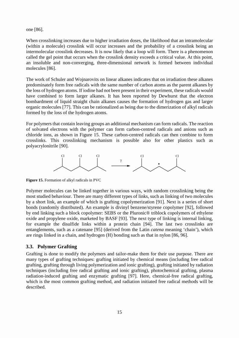
one [86]. When crosslinking increases due to higher irradiation doses, the likelihood that an intramolecular (within a molecule) crosslink will occur increases and the probability of a crosslink being an intermolecular crosslink decreases. It is now likely that a loop will form. There is a phenomenon called the gel point that occurs when the crosslink density exceeds a critical value. At this point, an insoluble and non-converging, three-dimensional network is formed between individual molecules [86]. The work of Schuler and Wojnarovits on linear alkanes indicates that on irradiation these alkanes predominately form free radicals with the same number of carbon atoms as the parent alkanes by the loss of hydrogen atoms. If iodine had not been present in their experiment, these radicals would have combined to form larger alkanes. It has been reported by Dewhurst that the electron bombardment of liquid straight chain alkanes causes the formation of hydrogen gas and larger organic molecules [77]. This can be rationalized as being due to the dimerization of alkyl radicals formed by the loss of the hydrogen atoms. For polymers that contain leaving groups an additional mechanism can form radicals. The reaction of solvated electrons with the polymer can form carbon-centred radicals and anions such as chloride ions, as shown in Figure 15. These carbon-centred radicals can then combine to form crosslinks. This crosslinking mechanism is possible also for other plastics such as polyacrylonitrile [90].
γCl Cl Cl Cl Cl
Figure 15. Formation of alkyl radicals in PVC Polymer molecules can be linked together in various ways, with random crosslinking being the most studied behaviour. There are many different types of links, such as linking of two molecules by a short link, an example of which is grafting copolymerization [91]. Next is a series of short bonds (randomly distributed). An example is divinyl benzene/styrene copolymer [92], followed by end linking such a block copolymer: SEBS or the Pluronic® triblock copolymers of ethylene oxide and propylene oxide, marketed by BASF [93]. The next type of linking is internal linking, for example the disulfide links within a protein chain [94]. The last two crosslinks are entanglements, such as a catenane [95] (derived from the Latin catena meaning ‘chain’), which are rings linked in a chain, and hydrogen (H) bonding such as that in nylon [86, 96]. 3.3. Polymer Grafting Grafting is done to modify the polymers and tailor-make them for their use purpose. There are many types of grafting techniques: grafting initiated by chemical means (including free radical grafting, grafting through living polymerization and ionic grafting), grafting initiated by radiation techniques (including free radical grafting and ionic grafting), photochemical grafting, plasma radiation-induced grafting and enzymatic grafting [97]. Here, chemical-free radical grafting, which is the most common grafting method, and radiation initiated free radical methods will be described.

16
In typical chemical-free radical polymer synthesis, a small molecule initiator such as Azobisisobutyronitrile (AIBN) is used to generate radicals. In this case, 2-cyanoprop-2-yl radicals are formed and react many times with the monomer (such as styrene) to form a polymer chain, which has a 1-cyano-1-methylethyl group at one end. A chain transfer agent such as 2-mercaptoethanol is able to terminate a growing polymer chain, and the resulting sulfur-centred radical can then initiate the growth of a new polymer chain. This chain will bear a 2-hydroxylethyl sulfide group. Such groups have been employed in chemical syntheses [98]. However, if a polymer such as polypropylene is treated to convert it into a radical, the polymer chain, bearing at least one free radical, will then react with the monomer as if it was an initiator. The original polymer will be at one end of the new polymer chain. In the radiation-initiated grafting technique, the free radicals can be formed by homolytic fission. The important difference between radiation-initiated grafting and chemical-initiated grafting is that an initiator is not needed. The medium is important, however, e.g. whether the conditions are aerobic or anaerobic. If it is aerobic conditions peroxides may be formed. The grafting can be carried out in three different ways: (1) pre-irradiation, (2) peroxidation and (3) mutual irradiation technique. To form the free radicals by the first method, the backbone polymer is pre-irradiated in the presence of an inert gas or in a vacuum. The irradiated polymer is then treated with the monomer (in a liquid or vapour state or in a solution). In the peroxidation method, the backbone polymer is high-energy radiated under aerobic conditions to form hydroperoxides or diperoxides (depending on the irradiation conditions and backbone polymer). The formed peroxy products are stable in nature and treated with the monomer at elevated temperatures, where the peroxides decomposes into radicals, and grafting can then be initiated. Good mixing of the individual components is of great importance to high grafting efficiency (which includes the suppression of the side reactions). Good mixing is dependent on the processing conditions of the extruder: the temperature should be high but not too high since that would cause degradation of the polymer and the initiator would decompose too quickly. Low throughput rates and high initiator levels are also important [99]. One advantage of this method is that the peroxy products can be stored for a long time before the actual grafting, but the disadvantage is the possibility of chain scissoring of the backbone polymer when exposed to direct irradiation [97]. The peroxidation method has been applied in this work. In the mutual irradiation techniques, both the polymer and the monomer are irradiated at the same time to form the free radicals and grafting [97]. 3.4. Polymer Degradation Plastic recycling is difficult when considering the degradation history of the polymers. The degradation of the polymer is the irreversible change in the chemical composition with time by the effects of free radical formation induced by UV light, consumption of processing stabilizers, heat, cold, radiation or mechanical stress [100]. Chain scission, depolymerization, (also referred to as unzipping), side-group reactions and carbonization are all types of polymer degradation [101], which all polymers (natural or synthetic, inorganic or organic) eventually undergo in an oxygen environment at elevated temperatures [102]. The chemical change almost always results in mechanical or aesthetic changes that make the plastics unsuitable for their original purpose [100]. Based on the knowledge that elevated temperatures degrade plastics, it is very important in plastics recycling to process at the lowest possible temperatures and at low shear forces [103], which otherwise tend to give local peaks in the temperature [104]. Reactive intermediates can take part in chemical reactions that alter the properties of the material. For example, if radicals are formed in an oxygenated plastic by the action of shear forces, these carbon-centred radicals can react with the oxygen (which is a diradical) to form peroxy radicals, which then react with another organic molecule to form a hydroperoxide.

17
When thermally activated the hydroperoxides tend to form hydroxyl radicals and alkoxy radicals. The alkoxy radicals are high in energy and tend to undergo reactions such as isomerization and β-scissions. The β-scissions result in a reduction in the chain length of the polymer. Oxidative degradation can be inhibited by the addition of antioxidants [100, 102], which can be consumed, especially after many recycling cycles of the plastics. For example, compounds such as BHT (2,6-di-tert-butyl-4-methylphenol) can be added to organic products such as plastics and foods. This compound donates a hydrogen atom to an oxygen-centred radical to form a stable molecule and a radical that is incapable of continuing the reaction [100]. 3.5. Physical and Chemical Ageing of Polymers Amorphous polymers (and the amorphous phases in crystalline polymers) are not in thermodynamic equilibrium below their glass transition temperature (Tg) caused by the cooling rate of the polymer. As the non-equilibrium state is unstable, the polymer chains will slowly relax over time by losing free volume (densification), called physical ageing [105]. A higher cooling rate gives a greater deviation from the equilibrium, see Figure 16, and urges the physical ageing, which occurs in the temperature range between Tg and the highest secondary relaxation transition (Tβ) since the chain mobility would be too low below Tβ [106]. These materials are identified as solidified super-cooled liquids with volume, enthalpy and entropy greater than they would have been at the equilibrium state. The physical ageing phenomenon causes changes in many properties, such as higher stiffness, brittleness and creep- and stress-relaxation rate, even after plastic parts have been produced by extrusion or injection moulding [105, 106, 107]. However, polymer blends can retard physical ageing since specific interactions, such as hydrogen bonding and dipole-dipole interactions, can restrict molecular mobility and thus increase long-term stability [105]. All amorphous, glassy polymers age in the same way, even the mechanical behaviour at small strains are very similar [106].
Figure 16. The influence of temperature on specific volume. The ageing range is between Tg and Tβ according to Struik [106] Chemical ageing, on the other hand, is the effect chemicals have on plastics, in other words ‘chemical resistance’ [107]. Chemical ageing is a non-reversible process while physical ageing is reversible [108]. Chemical ageing is related to the chemical principle of ‘like dissolves like’. This means that polyolefins are affected by hydrocarbon materials, while plastics containing oxygen, sulfur and other non-carbon and hydrogen atoms within their backbones are affected by chemicals containing similar materials [107].

18
3.6. Polymer Blending and Compatibility Compatibilizers were first used about forty years ago, and their use has increased over the last twenty-five years. In the last fifteen years they have commonly been used in commercial polymer blends [109]. They have two purposes: to reduce the domain size of the different polymers in the blend and thus improve its morphology and to enhance the adhesion between the domain boundaries by providing chemical bonding across them [110]. The miscibility of polymers also follows the principle ‘like dissolves like’, most of the times which is expressed in Equation 2, the free energy of mixing (∆Gmix) [111].
∆Gmix = ∆Hmix - T∆Smix (2)
It is necessary to have negative Gibb’s free energy to obtain a miscible polymer blend. Another condition that has to be fulfilled is that the mixing should be exothermic, which is not normally the case if there is no attraction between the polymers in the blend for example hydrogen bonding or dipole-dipole bonding. However, the entropy (∆Smix) is negligible for long polymer chains, leading to free energy of mixing only being negative if the heat of mixing (∆Hmix) is negative [112]. There are three different types of blends: miscible, partially miscible and immiscible blends, as presented in Table 3. Miscible blends only exhibit one glass transition temperature (Tg). In partially miscible blends, some parts of the two polymers are dissolved in each other and the blend exhibits two Tgs that are shifted towards each other. The blend has a fine phase morphology with satisfactory properties and is called compatible. In immiscible blends, the interphase region is limited between the blended polymers and coarse phase morphology [112]. Examples of immiscible blends are PS/PP and PS/PE [104], of partly miscible blends PS and poly(styrene-co-bromostyrene) PBrS [113], and of a miscible blend PS/PPO [114]. Table 3. Variation in properties for polymer blends in relation to their miscibility [115]
Immiscible Blends Partially Miscible Blends Miscible Blends
Complete phase separation Partial phase separation Homogenous
Poor interface leading to mechanical properties
Mechanical properties of individual component polymers
mostly retained
Mechanical properties of components averaged
ΔG>0 ΔG>0 ΔG<0 They show the two glass
transition temperatures of the component polymers
They show two glass transition temperatures, intermediate to the
component polymers
They show a single glass transition temperature

19
4. Experimental 4.1. Experimental Techniques 4.1.1. Gamma Irradiation The gamma irradiation was performed in a cobolt-60 (60Co) source named Gammacell 220 (Atomic Energy of Canada Limited, now trading as Norion). The initial dose rate in the irradiation chamber of the unit when it was refilled was 18 kGy·h-1 (2010) but declined during the project to 8 kGy·h-1 (2015). The dose rate was 14 kGy·h-1 on average for the tests in Articles I and III and 8 kGy·h-1 for the test in Article V. The dose rate was determined using the ferrous-cupric sulfate dosimeter test (04/02/2014), which works as a dosimeter up to 14 kGy with proper calibration [116, 117]. This dosimeter is independent of the oxygen concentration and organic impurities. Elemental Analysis Techniques: 4.1.2. Inductively Coupled Plasma Optical Emission Spectrometer (ICP-OES) Antimony in the liquid samples was measured using a Thermo iCAP 6500 inductively coupled plasma optical emission spectrometer (ICP-OES) from Thermo Scientific equipped with an autosampler and iTEVA software; see Figure 17 (middle). The samples and standards were diluted with Suprapur® nitric acid (1 M). The limit of detection for antimony is estimated at 0.05 ppm. Articles I and II. 4.1.3. Carbon, Hydrogen, Nitrogen (CHN) and Halogen Analysis Analysis of carbon, hydrogen and nitrogen (CHN analysis) and phosphorus (P) was carried out with a Carlo Erba 1112 elemental analyser at MEDAC Ltd in the United Kingdom. The bromine (Br) and chlorine (Cl) contents were measured with oxygen flask combustion followed by titration. When both halogens were measured in the same sample, ion chromatography was used instead of titration. The elemental analysis experiments were performed in duplicate. Articles I and V. 4.1.4. Scanning Electron Microscopy with Energy Dispersive X-ray Spectroscopy (SEM-EDX) SEM images were acquired with a backscattered electron detector (BSE-detector) using a Hitachi TM3000 table top SEM operated at 15kV acceleration voltage and approximately 650 pA beam current. Elemental maps and spectra were recorded with a Quantax70 (EDS detector) from Bruker Nano with an energy resolution of 130 eV for Mn Kα. Five spots (diameter 50 µm) were investigated along the 3 mm ABS plastic cross section of a recently made fracture surface to investigate the variation in the antimony content caused by leaching. A second SEM device was also used: a FEI Quanta 200 field-emission gun environmental scanning electron microscope (FEG ESEM) operated at 15 kV and coupled to an Oxford Inca 300 EDS system. Article I.

20
Figure 17. Equipment used for tensile testing (left), induced coupled plasma-optical emission spectroscopy (ICP-OES) (middle) and thermal testing by a dynamic mechanical thermal analysis (DMTA) machine (right) Mechanical Test Techniques: 4.1.5. Tensile Test The tensile test was performed on a Zwick 4031 with an Instron load cell (500 N) together with the testXpert® software; see Figure 17 (left). The equipment was used with the tensile speed of 2.8 mm min-1, which is approximately 10 % of the length of the dog bone’s waist. An additional test was also performed with different tensile speeds, 5.6, 28, 280 and 560 mm min-1, to investigate if the material became more brittle with increased speed. Articles III and IV. 4.1.6. Impact Test The impact properties were evaluated by both a Charpy Edgewise single notch test according to ISO 179/1eA and compared with un-notched samples. The samples were notched with a CEAST AN50, 0.1 mm at the time at 16 m min-1 to a final notch depth of 2.0 mm. The impact test equipment was an Instron CEAST 9050 with an impact energy of 0.5, 1.0 and 4.0 J, depending on the test sample. The impact specimens were prepared and tested at Swerea IVF. Ten test specimens were evaluated for each material and average values calculated with one standard deviation. The different blends that were prepared in a twin screw extruder, Coperion (Stuttgart, Germany), residence time 50 seconds in the extruder, screw speed 180 rpm and through put 6 kg hour-1, are presented in Table 7. Article V. Thermal Test Techniques: 4.1.7. Capillary Viscometry The viscosity measurements were performed on a Göttfert rheograph 2002 together with the WinRHEO software. Three repetitions were performed on each capillary length: 10, 20 and 30 mm. The diameter of the capillary was 1 mm and the machine held a temperature of 190 °C for all tests. The pressure transmitter is rated at 2000 bar and the shear rate went from 20 to 1500 s-1 in ten steps. The two first measurements were excluded due to instability. All the tests were subjected to both Bagley- and Rabinowitsch corrections. Articles III and IV. 4.1.8. Pyrolysis Gas Chromatography Mass Spectroscopy (GC-MS) Pyrolysis GC-MS was performed using an Agilent 5975 C GC/MSD machine fitted with a pyrolysis unit. The data were interpreted with OpenChrom software. Samples (non-irradiated and 1MGy gamma irradiated) were subjected to successive heating at 275, 360, 500 and 750 oC.

21
4.1.9. Dynamic Mechanical Thermal Analysis (DMTA) DMTA, was measured in a Rheometrics Solids Analyzer RSAII (AD94) with TA Orchestrator RSA2 software; see Figure 17 (right). Two curves were made for each material. Unless they matched, a third measurement was made. The first of the matching curves was used. Article V. 4.1.10. Fourier Transform Infrared Spectroscopy (FTIR) FTIR was performed using a Nicolet 6700 fitted with a DurasamplIR II. The spectra were recorded by means of an attenuated total reflectance attachment using a diamond crystal and OMNIC software. The treated samples of plastic were washed three times with distilled water before the measurement to remove any remaining leaching media. Article I. 4.1.11. X-ray Photoelectron Spectroscopy (XPS) The equipment used for the XPS measurement was a PHI 5500 instrument equipped with the monochromated Al-K(alpha) X-ray source (hv = 1486.6 eV). The regional detailed scan range was 0 to 250 eV. 4.1.12. Melt Flow Rate (MFR) MFR was measured at Swerea IVF in the equipment Ceast Melt Flow modular line according to the ISO 1133 standard. 4.2. WEEE Plastics Composition The WEEE plastics fraction (Stena 1) of about 600 kg was collected from Stena Technoworld in Halmstad (05/07/2011) and after washing treatment and melt-filtering, it was also called WEEEBR. Fourteen samples (with approximately 90 flakes on average) were taken from a falling stream in succession within three hours. Stena 1 was a low-density plastics fraction in which the brominated flame retardants had been sorted out, making it suitable for recycling. Another fraction (Stena 2) with a slightly higher density was also obtained from Stena Technoworld in Halmstad (12/01/2011). Three samples were collected with the coning and quartering sample splitting method [118]. The third fraction (Sims) was collected from Sims Recycling in Katrineholm (23/05/2011). Three samples were taken from a falling stream. The polymer identification of all the flakes was performed by interpretation of spectral peaks from FTIR. Table 4 summarizes the number of flakes, average flake weights and number of different materials found in the three WEEE plastics fractions. Table 4. Summary of flake weights and amounts of the investigated WEEE plastics fractions. The average flake mass and standard deviations are given.
WEEE plastic fraction
Number of samples analysed
Number of flakes analysed
Average flake weight (g)
Different materials detected
Stena 1 14 1226 1.9 (0.3) 29 Stena 2 3 340 1.0 (0.1) 25
Sims 3 230 5.3 (0.5) 31 The metal concentrations in the WEEE plastics were also assessed for all three WEEE plastics fractions. The metals and metalloids were either expected to be present in the plastics (Al, Ca, Cu, Fe and Zn) [119, 120] or considered hazardous substances (As, Cd, Ni, Pb and Sb) [27]. The samples were subjected to nitric acid leaching for 20 hours. The metals were analysed by ICP-OES. Furthermore, X-ray photoelectron spectroscopy (XPS) was used to study elements in Stena 1, to confirm the metals present and the absence of Br and Sb.

22
4.3. Material Preparation The Stena 1 fraction was prepared in several steps such as de-dusting and surface cleaning, melt-blending, melt-filtration and hot-die granulation at Next Generation Recycling Machinen in Feldkirchen, Austria. The recycling equipment used was an S:GRAN 85 extruder equipped with an Ettlinger rotating drum melt-filter and hot-die granulator. The extruder temperature profile was 210-230-190-190-210-230 oC (hopper to die) with a screw rotating speed rate of 145 rpm and a throughput of 280 kg/h. The continuous melt-filter removed the contaminants, which was approximately 1 wt% of the blend, and consisted of mainly non-thermoplastic materials. Drying is commonly recommended for ABS, typically 4 hours at 90 oC [121], due to the fact that acrylonitrile content is hydrophilic. Drying tests were performed for WEEEBR, though the main thermoplastics within WEEEBR are considered to be non-hygroscopic. It was found that less than 0.2 wt% of the moisture was absorbed when the WEEEBR was saturated by immersion in water. The drying of the WEEEBR as recommended for ABS before processing caused no change in stiffness (E), elongation at break (ɛb) or yield stress (σy), at least for the short-term properties. The long-term properties have not been investigated however. Pre-drying was only attempted for the virgin ABS prior to the repeated recycling. 4.4. Plastics Processing and Reprocessing In this work, mechanical recycling of plastics was applied. The melt-processing was performed by single screw extrusion (SSE), see Figure 18, twin screw extrusion (TSE), see Figure 19, or injection moulding (IM), see Figure 20.
Figure 18. The single screw extruder, Collin type 132, used for melt-processing the plastics
Figure 19. Schematic diagram of a twin screw extruder, used in mechanical recycling, where the plastic granulate is fed in the hopper (left), melted in the heated barrel, transported forward, mixed and finally extruded (to the right)

23
Figure 20. The injection moulding machine, Arburg Allrounder 221M 250-55, used for melt-processing the plastics 4.5. Antimony Leaching Dilute acid solutions ((a) citric, (b) tartrate and (c) nitric acid, illustrated in Figure 21) were tested for their ability to extract antimony from a computer casing made of ABS. The selected acids were chosen based on the work of Shotyk et al. and Bach et al., which indicated that antimony migrates from PET bottles into the bottled water or citric juice [51, 122]. A pre-test was performed on ashes to optimize the conditions used for the leaching of the ABS computer casing.
OHOH
O OHO O
(a) (b)
N
O
H
O
O
S
O
(c) (d)
O
O
OOH
OHOH
O
Figure 21. Molecular formulas for (a) citric acid, (b) tartrate acid, (c) nitric acid and (d) DMSO Dimethyl sulfoxide (DMSO), seen in Figure 21 (d), was used to dissolve the plastic and sodium hydrogen tartrate (0.5 M, both at room temperature and at 100-108 oC) to leach out the antimony in the equipment used and shown in Figure 23. The tartrate is needed as it binds to the antimony and forms an anionic (negatively charged) complex with it. This maintains the antimony in solution. Without the tartrate, the most stable form of the antimony will be as insoluble Sb2O3. Tartrate, which is formed by the deprotonation of tartaric acid has an unusually great ability to bind to antimony(III), each antimony binds to two tartrate ligands. Each tartrate binds with two carboxylate groups and two alkoxide groups to two different antimony atoms, thus forming a cyclic species, which is depicted in Figure 22.

24
Figure 22. Molecular structure of the complex formed from antimony(III) and tartrate anions as determined by X-ray crystallography. Carbon atoms are shown as dark grey, hydrogen atoms as white, oxygen atoms as red and antimony atoms as pink. Note that the complex is anionic. The potassium counter ions are not shown for reasons of clarity [123]. There are two forms of the Sb2O3: valentinite and senarmontite, and if all the antimony is present as 100 % in one of the forms, then a second leaching will theoretically recover more Sb. If both forms of Sb2O3 are present, however, and one is preferentially leached, then it is possible that the second leaching will not recover any more antimony from the waste plastic [124, 125].
Figure 23. Equipment for antimony leaching. Each leaching at an elevated temperature is performed in a round bottled flask equipped with a water cooled reflux condenser placed in a hot oil bath. CHN, Br and Sb measurements were performed by MEDAC Ltd. The CHN measurement was performed by a Carlo Erba 1112 elemental analyser, the Br content by oxygen flask combustion followed by titration, and the Sb content by acid digestion followed by analysis using a Varian Vista MPX ICP-OES. The elemental analysis experiment was performed in duplicate. For further details see Article I.

25
4.6. Gamma Irradiated ABS 4.6.1. Pyrolysis Gas Chromatography Mass Spectroscopy (GC-MS) To investigate the manner in which an ABS degrades when it is heated, a sample was examined with pyrolysis gas chromatography mass spectroscopy (GC-MS) as previously described in Section 4.1.8. 4.6.2. Hydrogen Cyanide Test A test for hydrogen cyanide (HCN) was performed on different types of ABS plastics, PC/ABS and WEEEBR; see Table 5. It is well known that hydrogen chloride (HCl) can be formed by radiolysis [126] or heating of PVC [127]. As ABS contains polyacrylonitrile regions, it was reasoned that it could form HCN under similar conditions. Both a chloride anion and a cyanide anion are groups that can leave a molecule with an electron pair in organic reactions. The cyanide anions are converted by the sodium salt of chloroamine T into cyanogen chloride, forming sodium chloride, tosyl amide (TsNH2) and hydroxide anions as side products; see Figure 24. The cyanogen chloride reacts with pyridine to form the dialdehyde, which then undergoes a condensation reaction with dimethyl barbaric acid to form a purple dye; see Figure 25 and Figure 26.
SO
O
N
Cl
Na
CN-
Cl-CNNaCl-
H2O
TsNH2-
OH--
Figure 24. Formation of cyanogen chloride from chloroamine T and cyanide anions

26
N
Cl-CN
N
CNCl
-
H2O
- HClN
HOH
CN
NH
CN
ON
CN
O
H2O
-CN22-
- 2H+O O
Figure 25. Conversion of pyridine into the dialdehyde by cyanogen chloride
OO
N N
O
OO
N N
O
OO
O
- H2O
N N
O
OO- H2O
N N
O
OO
N
NO
O
O
- H+
N N
O
OO
N
NO
O
O
Figure 26. Formation of the purple dye from dimethyl barbaric acid and the dialdehyde

27
A series of plastics containing polyacrylonitrile regions were gamma irradiated (600 kGy) before being immersed in dilute sodium hydroxide solution which are described in Table 5. Table 5. Materials tested for the formation of inorganic cyanide during irradiation
Plastic Type Manufacturer Grade Name
ABS BASF Terluran GP-35
ABS with flame retardant Sabic Cycolac S157
ABS/PC Bayer Covestro Bayblend FR 3000
WEEEBR - - 4.7. ABS Processing and Reprocessing 4.7.1. Melt Flow Rate on ABS and PC/ABS The melt flow rate was determined according to ISO 1133 and measured on a Modular Melt Flow 7024 produced by Ceast, Italy. One measurement per material was performed. 4.8. Styrene-Grafted Polypropylene (PP-g-St) Polypropylene Moplen 240P was produced by LyonellBasell, and the styrene, ethanol and toluene were purchased from Sigma-Aldrich. The styrene monomer was freed from inhibitor by washing three times with sodium hydroxide (NaOH, 2M) and three times with water to remove the NaOH. The other reagents were used without further purification. The polypropylene granulate was processed in a Collin extruder 3250-09-88 88 (screw length 694 mm, screw diameter 25 mm, and the rotational velocity was maintained at 50 rpm for all extrusions). The extruder had five heating zones, three along the cylinder, one at the adapter and one at the die, with the temperature profile: 150°C, 160°C, 170°C, 170°C, 180°C respectively. The extruded material was cut by a SG 10 Ni (Dreher) grinder (3x17 mm) to increase the surface area. A moisture content measurement was performed on PP pellets, and melt-blended and cut PP strips were used to determine the moisture content in it. The PP granules and strips were placed in an oven at 80 oC and weighed at different times (0, 15, 30, 45, 75 and 255 minutes). The sample amount of granules was 19.93 g and of strips: 20.02 g. 5.0 grams of PP was poured into thin ampoules (pre-sealed at the bottom). The neck was heated with a butane/air torch to soften the glass before the radius of the tube was reduced by pulling. After this treatment, the tubes were cooled. The ampoule was connected to the vacuum line. The ampoules were evacuated, sealed using the butane/air torch and transferred to the gamma irradiator where it was subjected to 50-300 kGy. The styrene monomer was tested for the presence of alkali by placing a drop in contact with pH indicator paper that had been pre-wetted with water. The styrene and ethanol were both deoxygenated by bubbling with nitrogen (1 hour each). The ampoules were opened inside a nitrogen-filled glovebox and the PP transferred to Schlenk tubes, and these were attached to a vacuum line. The styrene and ethanol were added to form a mixture that was 40 % (v/v) styrene. The grafting time was 24 hours and was stopped by sucking air through a funnel with a filtration paper and rinsing the PP with ethanol. The PP was put in a

28
Soxhlet thimble, which in turn, was placed in a Soxhlet head before being subjected to three hours of extraction with hot acetone. The treated product was first dried in air and then in a vacuum oven (60oC) for 24 hours before weighing. The melt-blending of TBV and the PP-g-St was performed in a mixing chamber (Brabender AEV 330) and plates were pressed (10x10x0.7 cm), Fontijne Holland TP200, to obtain 7 g batches of material containing 0, 5 and 20 wt% compatibilizer. The temperature was 200 oC. Test specimens, in the shape of dog bones, were manually punched out from the extruded strips using equipment according to the ISO 527-5A standard. The test specimens were conditioned at 25 (± 2) °C at 50 (± 5) % relative humidity for at least 24 hours prior to testing. 4.9. WEEEBR Blended with Compatibilizer The different compatibilizers that were blended with WEEEBR for the tensile tests are listed in Table 6. Table 6. Different compatibilizers blended with WEEEBR for tensile testing Used Compatibilizers Description Amounts of Compatibilizers Tested
Kraton G1652 E SEBS (30 wt% styrene) 0.83, 1.25, 2.5, 5, 10, 20 wt% Kraton FG1901 E SEBS-g-MAH 2.5, 5, 10 wt%
Royaltuf 372P20 SAN modified with EPDM 5, 10, 20 wt%
Fusabond P353 PP-g-MAH 0.83, 2.5, 5, 10 wt% The different blends with Kraton® G1652 E and WEEEBR for the impact test are shown in Table 7. Table 7. The WEEEBR blended with the compatibilizer Kraton® G1652 E (0-10 %) for the impact test Material Amount of Kraton® G1652 E (%)
WEEEBR reference 0
WEEEBR 2.5
WEEEBR 5
WEEEBR 10
WEEEBR (gamma irradiated granulate) 0
WEEEBR (gamma irradiated granulate) 2.5
WEEEBR (gamma irradiated granulate) 5
WEEEBR (gamma irradiated dog bones) 0
The melt flow rate was measured as described previously for ABS samples in Section 4.6.1.

29
5. Results and Discussion 5.1. WEEE Plastics Composition The composition of the recycled WEEE plastics fraction Stena 1 (WEEEBR after melt-filtration and removal of 1.2 wt% of non-thermoplastic contaminants; see Figure 29) based on the FTIR analysis of approximately 1200 flakes is shown in Figure 27. A pressed plate of Stena 1 with millimetre-sized particles is depicted in Figure 28. The main constituents were styrene-based plastics (84 wt%) and polyolefins (12 wt%). Within styrene-based plastics, the biggest fraction was PS/HIPS (42 wt%) (also included PS-containing acrylate and poly(vinyl cyclohexane)). A large amount of ABS (38 wt%) was present. This fraction included the ABS plastics-containing acrylate ester monomers and the styrene-acrylonitrile copolymers. The other styrene-based plastics were polyphenylene ether blended with styrene butadiene (PPE/SB), the styrene methyl methacrylate copolymers (SMMA) and PC/ABS. The polyolefins were mainly PP (10 wt%, some of the PP grades were talc-filled) and a small amount of PE (1.5 wt%). The remaining thermoplastics were PVC, polyethylene terephthalate (PET) and polyamide (PA).
Figure 27. Plastics composition (in wt%) of Stena 1 The main thermoplastic elastomer materials present were ethylene-vinyl acetate copolymers (EVA), poly(vinyl butyral), poly(ethylene:propylene:diene) and poly(ethylene:vinyl acetate:vinyl chloride). While the majority of the material was thermoplastics, a small part of the plastics blend consisted of non-thermoplastic contaminants, approximately 1.2 wt%, which included silicone rubbers, crosslinked PUR, paper materials and wood. The wood forms three products when heated: solid charcoal, wood-tar and wood-gas [128]; see Figure 27.
Figure 28. Photograph showing the poor material quality of a pressed WEEE (Stena 1) thermoplastics plate (before melt-filtration). The millimetre-sized particles consisted of non-thermoplastic contaminants, mainly rubbers.

30
Other than some aluminium foil, no metallic materials were found. The contaminants have the potential to cause serious problems during mechanical recycling, so they were removed by melt-filtration.
Figure 29. WEEEBR granules (right) formed from melt-blending and melt-filtration of WEEE plastic flakes (left)
Figure 30. The plastics composition with contaminants for Stena 1, Stena 2 and Sims. The bars show the variation width based on three samples for Stena 2 and Sims. Stena 1 is included for comparison and the values are based on fourteen samples. The variation widths are shown in Article II. Figure 30 shows the combined plastics composition (wt%) with the present contaminants for Stena 1, Stena 2 and Sims (Stena 1 was added for comparison). The styrene-based fractions were dominant in all three fractions. Larger amounts of ABS and PS/HIPS were found in Stena 1 than in the other fractions. However, PC/ABS was found in a much greater amount in Stena 2 than in
0 5 10 15 20 25 30 35 40 45
Residue fraction
Metal
Glass
Wood (paper)
Polyurethanes
Rubbers
Other thermoplastics
PP
PE
PPE+SB
PS/HIPS
PC/ABS
ABS
Weight Fraction (wt%)
Stena 1
Stena 2
Sims

31
Stena 1 and Sims. The other thermoplastics (PC; PVC; PA; SMMA; PMMA; polyoxymethylene, POM; and poly(butylene terephthalate, PBT)) were found in large quantities in Stena 2 and Sims. The rather high amount of rubber in Stena 2 can impede the recycling of the fraction. It is noteworthy that approximately 5 wt% of glass was present in the Sims sample while no glass was found in Stena 1 or Stena 2. Furthermore, both wood and metals were found to higher extent in the Sims fraction in Stena 1 and Stena 2. 5.1.1. Metal Content in the Investigated WEEE Plastics The metal content of the WEEEBR fraction was investigated by surface leaching of the plastic flakes (see Article II) and compared with bulk leaching by complete decomposition of the plastics in a wet ashing process at MEDAC Ltd. These results are shown in Table 8 with the accuracy of ± 0.30 % for the MEDAC Ltd method. The high and similar results of Ca indicated that most Ca is located at the surface of the plastic. The surface leaching seemed to be efficient for extracting Al, Cu, Fe, Ni, Pb and Zn, since similar results were obtained in both studies. On the other hand, the levels of extracted Mg and Cd were significantly higher in the bulk leaching. These results indicate that the plastic contains some magnesium compound within the bulk of the plastic. This may be talc (Mg3Si4O10(OH)2), which has previously been described in Section 2.5., and is commonly found in PP. Polypropylene was observed during the FTIR characterization of Stena 1. The presence of magnesium was confirmed by XPS, which is shown in Figure 26. The Cd level (70 ppm) was ten times higher than the amount found in the surface leaching and close to the threshold value of 100 ppm set by RoHS [39]. Due to the low content of PVC in Stena 1, the Cd is probably attributed as a colour pigment rather than a stabilizer [129]. Table 8. Metal contents in Stena 1 according to bulk leaching at MEDAC Ltd (± 0.30 % uncertainty) and surface leaching at Chalmers University of Technology
Metal MEDAC Ltd (ppm) Chalmers University of Technology (ppm)
Al 370 280
Ca 6300 6100
Cd 70 5
Cu 60 50
Fe 880 500
Mg 670 150
Ni 25 20
Pb 80 110
Zn 310 330
The majority of the toxic metals (As, Cd, Ni and Sb) were not detected with ICP-OES, with the exception of Pb, with some samples containing 200 ppm. However, this is still far under the threshold limit for Pb set by RoHS [39]. The large amounts of Ca in Stena 1 and 2 can be explained by the use of calcium carbonate (CaCO3) in the density bath to which the material was subjected. CaCO3 can be used as a filler in plastics and is able to scavenge acidic decomposition products, which can be formed during melt-processing. For this reason, it was argued that the CaCO3 would not inhibit mechanical recycling but instead be beneficial since both Fe and Cu can cycle between two oxidation states, making them potential catalyses for the degradation of polymer chains [130]. Since large amounts of Fe were found (500-1000 ppm), this can be a problem in WEEE plastics recycling. Finally, rather high levels of Zn were found (310-330 ppm), which can also accelerate photo-degradation of polyolefins [131].

32
Figure 31. Close-up of the low binding energy range (0-250 eV) versus counts per second of a survey spectrum (0-1350 eV) from a fracture surface of melt-blended Stena 1 The expansion of the XPS low binding energy spectra, see Figure 31, indicated the presence of Si and Mg in addition to the more common C, O and N. The XPS experiment was unable to find evidence of the presence of Br and Sb. These elements, if present, should have caused at least one prominent peak each in the examined spectral range. Furthermore, the melt-blended Stena 1 blend seemed to be relatively homogeneous (at least within the 100-200 µm range, which is the smallest area the XPS could resolve with the given settings) as several survey spectra taken at different parts of the blend were very similar. 5.1.2. Pyrolysis GC-MS of WEEEBR The pyrolysis GC-MS of WEEEBR indicated the presence of PS and PP but little (if any) PE. Neither bromine nor chlorine compounds were found to confirm the results obtained by MEDAC and XPS that the material was halogenated flame retardant free (Article II) and only traces of other additives were detected. This can be explained by the consumption of antioxidants when the material has been remelted several times [132]. The repeated appearance of peaks (at 55-74 minutes) on the 750 oC curve in Figure 32, are due to the sequential losses of oligomers of propylene (C3H6) from a polymer suggesting the presence of polypropylene in the sample. In the lower temperature pyrogram, shown in Table 9, oligomers of styrene were observed, which is consistent with the fact that the WEEEBR contained large amounts of the styrene-based plastics. When the plastic was heated to a higher temperature (500 and 750 oC), tabulated in Table 10 and Table 11, and ignoring the degradation products of PP, the observed products were similar to those obtained by the pyrolysis of ABS.
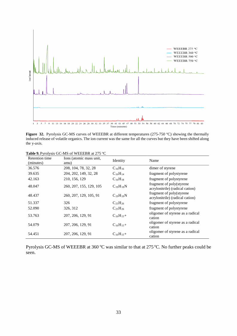
33
Figure 32. Pyrolysis GC-MS curves of WEEEBR at different temperatures (275-750 oC) showing the thermally induced release of volatile organics. The ion current was the same for all the curves but they have been shifted along the y-axis. Table 9. Pyrolysis GC-MS of WEEEBR at 275 oC
Retention time (minutes)
Ions (atomic mass unit, amu) Identity Name
36.576 208, 104, 78, 32, 28 C16H16 dimer of styrene 39.635 204, 202, 149, 32, 28 C16H14 fragment of polystyrene 42.163 210, 156, 129 C16H18 fragment of polystyrene
48.047 260, 207, 155, 129, 105 C19H18N fragment of poly(styrene acrylonitrile) (radical cation)
48.437 260, 207, 129, 105, 91 C19H18N fragment of poly(styrene acrylonitrile) (radical cation)
51.337 326 C25H26 fragment of polystyrene 52.090 326, 312 C25H26 fragment of polystyrene
53.763 207, 206, 129, 91 C16H15+ oligomer of styrene as a radical cation
54.079 207, 206, 129, 91 C16H15+ oligomer of styrene as a radical cation
54.451 207, 206, 129, 91 C16H15+ oligomer of styrene as a radical cation
Pyrolysis GC-MS of WEEEBR at 360 oC was similar to that at 275 oC. No further peaks could be seen.

34
Table 10. Pyrolysis GC-MS of WEEEBR at 500 oC Retention time (minutes) Ions (amu) Identity Name
1.310 54, 53 C4H6 butadiene 1.533 53, 52 C3H3N acrylonitrile 3.792 92, 91 C7H8 toluene 5.512 108 C8H12 butanedinitrile 5.725 126, 83, 70 C9H18 trimer of propylene 6.385 106, 91 C8H10 ethylbenzene 7.501 104, 103 C8H8 styrene 10.763 118, 107 C9H10 styrene + CH2 35.489 208, 130, 115, 104, 91 C16H16 dimer of styrene 38.408 210, 144 C16H18 oligomer of styrene
44.979 260 C19H18N fragment of poly(styrene acrylonitrile) (radical cation)
46.495 260 C19H18N fragment of poly(styrene acrylonitrile) (radical cation)
45.928 260 C19H18N fragment of poly(styrene acrylonitrile) (radical cation)
52.137 312, 208, 207, 194, 117, 91 C24H24 trimer of styrene Table 11. Pyrolysis GC-MS of WEEEBR at 750 oC
Retention time (minutes) Ions (amu) Identity Name
7.789 104, 103 C8H8 styrene 10.866 118, 116 C9H10 α-methylstyrene 18.524 128 C10H8 naphthalene (weak) 35.461 208 C16H16 dimer of styrene 52.137 312 C24H24 trimer of styrene
5.1.3. The Influence of Gamma Irradiation Dose on WEEEBR The MFR increased with increasing gamma irradiation doses up to 100 kGy (indicated a less viscous melt) and then decreased to 600 kGy (indicated a more viscous melt) as described in Figure 33. This behaviour can be explained by cleavage of the polypropylene chains in the lower dose irradiation (below 100 kGy) and above 100 kGy, crosslinking becomes the dominant process. As a result the viscosity of the melt first decreases and then increases again. As the rheology experiments, see Article III, performed at 190 oC with ABS which had been subjected to either 10, 100 or 200 kGy of gamma irradiation or no irradiation indicated that only a moderate increase in viscosity of the ABS occurred it can be reasoned that the melt flow rate is dictated largely by the properties of the polypropylene domains in the plastic.

35
Figure 33. Influence of the gamma irradiation dose (0, 50, 100, 200 and 600 kGy) on WEEEBR as a function of the melt flow rate (g/10 minutes, 220 oC, 5 kg) 5.1.4. Technical Data Sheet of WEEEBR The technical data sheet of WEEEBR has been compiled in Table 12. The processing information in Table 12 shows that WEEEBR can be processed under similar conditions to those of virgin ABS and HIPS. The mechanical properties indicate that WEEEBR is a brittle material with generally low values. The Tg is similar to previously reported values of virgin ABS and HIPS [133, 134]. Comparisons between the non-compatibilized and the compatibilized WEEEBR have been made in Section 5.6.7. and Table 26. Table 12. Technical data sheet of WEEEBR
Composition
100 wt% (HIPS, 42 wt%; ABS, 38 wt%; PP, 10 wt%; remaining, 10 wt%)
Processing information Value Unit
Extrusion temperature range 170-200 oC
Injection moulding temperature range 200-220 oC
Mould temperature 60 oC
Mechanical properties Value Unit
Tensile modulus 1.2-1.3 GPa
Yield stress 26-32 MPa
Elongation at break 1.7-5.0 %
Charpy impact strength 1.6-2.3 kJ/m2
Thermal properties Value Unit
Glass transition temperature (Tg) 100-115 oC
Melting peak temperature (Tm) 160-170 oC
1st onset of thermo-oxidative degradation (Tox) 180-190 oC
2nd onset of thermo-oxidative degradation (Tox) 210-220 oC
Melt flow rate (220 oC, 5 kg) 29 g/10 minutes
Applications
EEE, cable reel
29
45
65
42
7,7
0
10
20
30
40
50
60
70
0 100 200 300 400 500 600
Mel
t Flo
w R
ate
(g/1
0 m
inut
es)
Gamma Irradiation Dose (kGy)
WEEEBR

36
5.2. Antimony Leaching DMSO in combination with sodium hydrogen tartrate worked as a leaching medium of antimony from the ABS plastic. As can be seen in Table 13, the leaching efficiency was almost 50 %. Pure DMSO, aqueous sodium hydrogen tartrate and water were not successful on their own as leaching media for antimony. Sodium hydrogen tartrate in DMSO could leach antimony while sodium hydrogen tartrate in water could not. This can be explained by the fact that the hot DMSO dissolves the plastic, thus allowing the tartrate solution to come into contact with the antimony deep within the plastic. The antimony that might have been present on the surface could have migrated and disappeared with time.
Table 13. Leaching efficiency of antimony (%) from an ABS computer casing using different leaching media
Leaching medium
Sodium hydrogen tartrate in DMSO
DMSO Sodium hydrogen tartrate in water
Water
Leaching condition
Heated Heated Room
temperature Heated
Room temperature
Antimony leaching (%)
47.9 0 0 0 0
Comparing this result with other work done in the industry, the Centrevap process [35] should be mentioned. This process was developed within the Waste Resources Action Programme (WRAP). It was developed after the Creasolv® process by Fraunhofer Institute IVV in cooperation with CreaCycle GmbH, which is used for removing BFR in styrene plastics. The aim of the Centrevap process is to remove both BFR and impurities such as Sb2O3, fillers, pigments and stabilizers from the styrene-based plastic HIPS. Ground plastics are dissolved in toluene and the suspension (heated to 65 oC) is then pumped through a filter and centrifuges. The removed particles, un-dissolved plastics, metals and fillers from the dissolved plastics and any un-dissolved BFR and Sb2O3 are further processed to a dry powder where the toluene is evaporated. The powder is then melted and extruded before the polymer is pelletized. The final product contains less than 1 % solvent. The result of their tests, however, showed that the bromine removal content was not sufficiently high, though the antimony removal level was almost 60 % [35]. The results of the elemental analysis of CHN, Br and Sb in the ABS plastic from a post- consumer computer casing are shown in Table 14 with the accuracy of ± 0.30 %. The N level comes from the acrylonitrile groups in ABS. The mass ratio of Br:Sb was 2:1, which, in comparison, is a high level of Sb to previously reported ratios of 3-4:1 for mixed WEEE plastics [135, 136, 137]. Table 14. Elemental composition in ABS computer casing
Element C H N Br Sb
Content (wt%) 70.8 6.7 4.4 9.6 4.8
5.3. Gamma Irradiated ABS The effect of a gamma irradiation dose on ABS was evaluated with tensile properties and observed and illustrated in Figure 33. The stiffness was unchanged with an increasing dose, which can also be seen in Figure 33. This is contradictory to the results of Perraud et al. They observed an increase in stiffness for the hydrogenated nitrile butadiene rubber (HNBR), an elastomer commonly used in the automotive and printing industries that includes two components of ABS, A and B, when it is irradiated with an electron beam [138]. The elongation at break decreased with an increasing

37
irradiation dose, which was the same behaviour as we noticed in our test, as shown in Figure 34. The acrylonitrile content influence how sensitive different plastics are to gamma irradiation. Cardona et al. analysed acrylonitrile/butadiene rubber and saw an increased effect on the rubber with an increasing acrylonitrile content when it was irradiated. The acrylonitrile part was also more sensitive to gamma irradiation than the butadiene part and, lastly, the reactions observed were the consumption of double bonds and crosslinking, no chain scissoring occurred [139]. This behaviour can explain the increase in viscosity noticed in our comparison of non-irradiated and gamma irradiated ABS.
Figure 34. The gamma irradiation dose effect (0, 10, 50 and 400 kGy) on ABS with respect to tensile properties The gamma irradiation dose effect of viscosity is shown in Figure 35. The viscosity increased with an increased gamma irradiation dose, indicating that crosslinking has occurred.
0
5
10
15
20
25
30
35
40
Yield Stress (MPa) Elongation at Break (%) Stiffness (GPa) 0.1-1 %
Reference ABS
10 kGy
50 kGy
400 kGy

38
Figure 35. Gamma irradiation dose effect (0-200 kGy) on average viscosity from non-irradiated and gamma irradiated ABS. The viscosity increased by 6 % for 10 kGy, 12 % for 100 kGy and 18 % for 200 kGy. 5.3.1. Pyrolysis GC-MS of an ABS Containing Brominated Flame Retardant Within the 275, 360 and 500 oC pyrolysis, there are GC-MS curves (pyrograms) for non-irradiated ABS (Cycolac S157) showing evidence of debromination. However, when the different samples were examined it was found that the chemical nature of the semi-volatile compounds differed between the non-irradiated and the 1 MGy-irradiated sample. Evidence of the conversion of tetrabromobisphenol A units into less brominated analogues was seen. It has been observed by others that polychlorobisphenyls dissolved in organic solvents and trichloroanisole in cork [140] are dehalogenated by gamma irradiation [141]. The pyrograms recorded at 500 and 750 oC for the non-irradiated (Figure 36) and irradiated (Figure 37) ABS were very similar, suggesting that little chemical change of the polymer occurred. Many of the compounds identified in the pyrolysis GC-MS experiment were reported to form during the pyrolysis of ABS at 525 oC, which confirms that the plastic was an ABS [142]. When the pyrograms recorded at 360 oC for both 1 MGy gamma irradiated and non-irradiated ABS, shown in Figure 38, are compared it is clear that the ratio of the peak sizes for tetrabromobisphenol A (68 minutes) and tribromobisphenol A (63 minutes) changed in favour of the tribromo compound. It is important to note that even a dose of 1 MGy was unable to destroy all of the tetrabromobisphenol A, as is seen later in Section 5.4.2., Table 20 where a dose of 600 kGy causes ABS to become so highly crosslinked that it is no longer a thermoplastic. The inability of gamma irradiation to destroy the brominated flame retardant and leave a usable thermoplastic was disappointing. As bromine is less electronegative than chlorine, it is reasonable to assume that the brominated flame retardants will have a smaller affinity for solvated electrons as the chlorine-containing compounds found in corks and transformer oil. As a result, a higher dose would be required to fully dehalogenate the brominated flame retardants. This result was confirmed using a similar experiment with the ABS from the computer casing and a 4 MGy gamma dose. Gamma irradiation is not a suitable alternative to the removal of brominated flame retardants by extraction with organic solvents.
125
130
135
140
145
150
155
ABS non-irradiated ABS 10 kGy ABS 100 kGy ABS 200 kGy
Vis
cosi
ty (k
Pa)

39
Figure 36. Pyrolysis GC-MS curves of a non-irradiated ABS at different temperatures (275-750 oC) showing the thermally induced release of volatile organics. The ion current was the same for all the curves but they have been shifted along the y-axis.
Figure 37. Pyrolysis GC-MS curves of 1 MGy-irradiated ABS at different temperatures (275-750 oC) showing the thermally induced release of volatile organics. The ion current was the same for all the curves but they have been shifted along the y-axis.

40
Figure 38. Pyrolysis GC-MS curves of non-irradiated ABS (360 oC) showing the thermally induced release of volatile organics compared with 1 MGy gamma irradiated ABS (360 oC). The ion current was the same for both curves but they have been shifted along the y-axis. As seen in Table 15 and Table 16, moderate heating of ABS causes the emission of brominated bisphenols and some small oligomers from the production of the plastic. All the brominated organic compounds formed from the plastic relate to the flame retardant. Table 15. Pyrolysis GC-MS of the non-irradiated ABS at 275 oC
Retention time (minutes) Ions (amu) Identity Name
31.662 252 C6H4OBr2 dibromophenol 40.601 294, 292,290 C9H8OBr2 (292) fragment of flame retardant
49.980 261, 207, 129, 128 SAA, ASA or AAS short oligomers from production
51.086 326, 311, 249, 248 C25H26 fragment of polystyrene 51.514 261, 230, 144, 91 unknown -
62.761 465, 450 C15H13O2Br3, C14H10O2Br3
tribromobisphenol A
67.700 529, 527 C15H12O2Br4 tetrabromobisphenol A Table 16. Pyrolysis GC-MS of the non-irradiated ABS at 360 oC
Retention time (minutes) Ions (amu) Identity Name
31.585 252 C6H4OBr2 dibromophenol
62.650 278 C8H6OBr2 degradation product of bisphenol A
67.567 544, 529 C15H12O2Br4 tetrabromobisphenol A Further heating of the ABS, tabulated in Table 17 and Table 18, formed a complex mixture of products. As the irradiated and non-irradiated samples had almost identical pyrograms, the experiment suggests that a radiation dose of 1 MGy will not have any effect on the production of pyrolysis oil from ABS. While a good yield (60 %) of styrene can be obtained from the pyrolysis of polystyrene with either a platinum or rhodium on alumina catalyst [143], the greater complexity of ABS is likely to impede the conversion of ABS into a pure monomer.
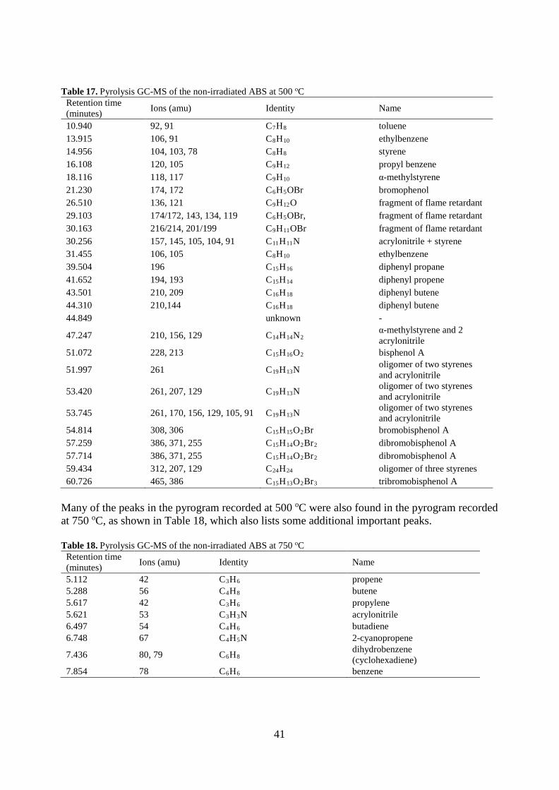
41
Table 17. Pyrolysis GC-MS of the non-irradiated ABS at 500 oC
Retention time (minutes) Ions (amu) Identity Name
10.940 92, 91 C7H8 toluene 13.915 106, 91 C8H10 ethylbenzene 14.956 104, 103, 78 C8H8 styrene 16.108 120, 105 C9H12 propyl benzene 18.116 118, 117 C9H10 α-methylstyrene 21.230 174, 172 C6H5OBr bromophenol 26.510 136, 121 C9H12O fragment of flame retardant 29.103 174/172, 143, 134, 119 C6H5OBr, fragment of flame retardant 30.163 216/214, 201/199 C9H11OBr fragment of flame retardant 30.256 157, 145, 105, 104, 91 C11H11N acrylonitrile + styrene 31.455 106, 105 C8H10 ethylbenzene 39.504 196 C15H16 diphenyl propane 41.652 194, 193 C15H14 diphenyl propene 43.501 210, 209 C16H18 diphenyl butene 44.310 210,144 C16H18 diphenyl butene 44.849 unknown -
47.247 210, 156, 129 C14H14N2 α-methylstyrene and 2 acrylonitrile
51.072 228, 213 C15H16O2 bisphenol A
51.997 261 C19H13N oligomer of two styrenes and acrylonitrile
53.420 261, 207, 129 C19H13N oligomer of two styrenes and acrylonitrile
53.745 261, 170, 156, 129, 105, 91 C19H13N oligomer of two styrenes and acrylonitrile
54.814 308, 306 C15H15O2Br bromobisphenol A 57.259 386, 371, 255 C15H14O2Br2 dibromobisphenol A 57.714 386, 371, 255 C15H14O2Br2 dibromobisphenol A 59.434 312, 207, 129 C24H24 oligomer of three styrenes 60.726 465, 386 C15H13O2Br3 tribromobisphenol A
Many of the peaks in the pyrogram recorded at 500 oC were also found in the pyrogram recorded at 750 oC, as shown in Table 18, which also lists some additional important peaks. Table 18. Pyrolysis GC-MS of the non-irradiated ABS at 750 oC
Retention time (minutes) Ions (amu) Identity Name
5.112 42 C3H6 propene 5.288 56 C4H8 butene 5.617 42 C3H6 propylene 5.621 53 C3H3N acrylonitrile 6.497 54 C4H6 butadiene 6.748 67 C4H5N 2-cyanopropene
7.436 80, 79 C6H8 dihydrobenzene (cyclohexadiene)
7.854 78 C6H6 benzene

42
5.3.2. Hydrogen Cyanide Test The materials tested for hydrogen cyanide are shown in Table 19. It was found that only ABS (Terluran GP-35) contained cyanide anions. A purple dye (indicating the presence of cyanide) was formed and can be seen in Figure 39. The other solutions, which did not contain any cyanide, can also be seen in Figure 39. It was not possible to detect any formation of hydrogen cyanide from the ABS (Cycolac S157), which contained a brominated flame retardant together with antimony under these conditions. WEEEBR, which contained 38 wt% ABS and was free from flame retardants, did not show evidence of hydrogen cyanide either. This result was surprising since we had reasoned that it would behave in a similar way to pure ABS. The fact that these two plastics did not release hydrogen cyanide after irradiation suggests that the plastics either (1) never formed the hydrogen cyanide or (2) it was unable to leave the plastics. As aqueous hydrogen cyanide is a weaker acid than carbonic acid, it is unlikely that a carbonate additive was able to fix the hydrogen cyanide in the plastic as a salt such as calcium cyanide. It was reasoned that as the hydrogen cyanide is likely to form from cyanide anions formed by the reaction of solvated electrons with the polymer. The consumption of the solvated electrons by the brominated flame retardant could explain why cyanide was not found. Table 19. Materials tested for the formation of inorganic cyanide during gamma irradiation
Plastic Type Manufacturer Grade Name HCN detected
ABS BASF Terluran GP-35 Yes
ABS with flame retardant Sabic Cycolac S157 No
ABS/PC Bayer Covestro Bayblend FR 3000 No
WEEEBR - - No
Figure 39. Hydrogen cyanide test from left to right: control sample, ABS Terluran GP-35 (purple), ABS Cycolac S157, WEEEBR, PC/ABS Bayblend FR3000. Only the purple sample indicates hydrogen cyanide anions in the sample. The blend of mostly PC/ABS did not form hydrogen cyanide in this experiment. This result could be explained by the fact that the polyacrylonitrile content of the plastic was very low or that the solvated electrons were lost by reaction with the PC, the flame retardant additive or some other

43
solvated electron trap, such as oxygen. Oxygen is able to react with reducing reactive species such as the solvated electron, and it was therefore reasoned that to deoxygenate rigorously many tonnes of plastic waste before treatment would be impractical. An industrial process that uses radiation to treat non-deoxygenated plastic waste would be more attractive. It was concluded that experiments with plastics that were initially oxygenated are more industrially relevant. The crosslinking process in deoxygenated PVC occurs when the radical anions formed by the reaction of the polymer and solvated electrons fragment into chloride anions and carbon-centred radicals. We reasoned that a similar process can occur in the polyacrylonitrile. The resulting radicals can either combine two polymer chains or undergo some other reaction that forms a covalent bond between polymer chains. 5.4. ABS Processing and Reprocessing The multiple-recycling and accelerated ageing of gamma irradiated ABS was an initial step to see the behaviour of one of the main constituents of WEEEBR. To make it comparable with previous tests carried out by Boldizar et al. and to have better control of the history of the plastic, virgin material was used. The previous results by Boldizar et al. show that the reduction of elongation at break could be attributed to physical ageing of the styrene-acrylonitrile (SAN) phase and to thermo-oxidative ageing of the polybutadiene phase [144]. 5.4.1. Mechanical Properties of Aged and Reprocessed ABS The hypothesis for the ageing and reprocessing test of ABS was that the gamma irradiation would counteract the expected accelerated ageing, hence degrading of the ABS, and withstand or even increase the mechanical properties. Previous results presented by Boldizar and Möller indicated that the elongation at break increased for each cycle in the extrusion steps up until cycle 6 [144]. The stiffness, found in Figure 40, is stable for the first and second cycles, but decreases similarly in cycle 3 for both the sample irradiated with 10 kGy between each cycle and the sample irradiated before the first cycle (40kGy). The reference ABS sample is stable for all four cycles. The deviation of the elongation at break, see Figure 41, was very high, however, so it was difficult to draw any conclusions about any change occurring during the reprocessing cycles and ageing.
Figure 40. Stiffness comparisons (GPa) between the reference ABS, 10 kGy between each cycle and 40 kGy gamma irradiated materials
0,8
0,9
1,0
1,1
1,2
1,3
0 1 2 3 4
Stiff
ness
(GPa
)
Cycle Number
Reference ABS10 kGy between cycles40 kGy

44
Figure 41. Elongation at break (%) comparison between reference ABS, 10 kGy between each cycle and 40 kGy gamma irradiated material. The error bars are bigger in size than the differences between the plastics and are therefore not shown. 5.4.2. Melt Flow Rate on ABS, PC/ABS, PP and WEEEBR When a sample of ABS that was free of flame retardants and other additives was irradiated at doses between 10 and 200 kGy, it was found that the viscosity was increased by the irradiation. This indicated that the average chain length of the polymers had been increased by crosslinking. Our hypothesis at the time was that the main crosslinking process involved the loss of cyanide from a radical anion followed by other reactions as shown in Figure 42.
N N NC
N
N
N
P
P
N N
RR
N NR
R
Figure 42. Fragmentation of the radical anion followed by crosslinking either by addition to a double bond or dimerization of radicals. P• denotes a polymer radical while R-CH=CH-R denotes an alkene unit within an unsaturated polymer such as the polybutadiene portion of the ABS. It was reasoned that if the formation of radicals from the acrylonitrile regions of the ABS (which is accompanied by the release of inorganic cyanide) was suppressed by the presence of a solvated electron trap, such as a brominated flame retardant, no crosslinking would occur. To test this
0
5
10
15
20
25
0 1 2 3 4
Elon
gatio
n at
Bre
ak (%
)
Cycle Number
Reference ABS10 kGy between cycles40 kGy

45
hypothesis, the melt flow rate of granulate of an ABS, containing a brominated flame retardant, (Cycolac S157) was measured before and after gamma irradiation. It was found that after the 600 kGy irradiation, the plastic underwent considerable crosslinking, so much that it was impossible to melt the granules at 220 oC, as shown in Table 20. This transformation, from a material which can be melted and extruded through a capillary at 220 oC, into a solid that cannot be melted at a temperature suitable for extrusion makes it unsuitable for mechanical recycling after this high irradiation dose. This crosslinking of the ABS containing the brominated additive suggests that the hypothesis that cyanide loss (Section 5.3.2.) accompanies crosslinking was wrong. The PC/ABS blend behaved differently to the ABS and PP. In common with Titomanlio et al. [145], we found that a large dose of gamma rays decreased the viscosity of the polycarbonate. Table 20. Melt flow rate (g/10min) of ABS, ABS/PC and WEEEBR with and without gamma irradiation (600 kGy)
Material Melt flow rate (g/10min), 220 oC, 5 kg
Non-irradiated 600 kGy Gamma irradiated
ABS Terluran GP-35 7.4 Viscosity too high for measurement ABS Cycolac S157 21.5 Viscosity too high for measurement
PC/ABS Bayblend FR 3000 44.5* Viscosity too low for measurement
PP Moplen 240P 15** Failure to melt
WEEEBR 29 7.7 * 260 oC 5 kg ** 230 oC 2.16 kg It can be reasoned that radicals produced by the action of solvated electrons on the brominated flame retardant can take part in crosslinking reactions. If brominated aromatic groups accept a solvated electron to form a radical anion, this can decompose to form a bromide anion and an aryl radical. As a class, aryl radicals have high energy compared with other carbon-centred radicals. These aryl radicals could combine to form sigma bonds between aryl groups or attack multiple bonds in other molecules. It has been shown that even under aerobic conditions, chlorobenzene can form biphenyl when it is irradiated [146]. As aryl and other radicals can react with alkenes [147], it is possible that the aryl radicals formed from the brominated flame retardant could crosslink by reacting with the polybutadiene regions of the ABS. Some small molecule brominated aromatic flame retardants are present in plastics and these could react several times with solvated electrons to form links to other polymer chains. While the macromolecular brominated flame retardants such as brominated polystyrene could form the first crosslink by reacting only once. From these observations, a new hypothesis “that the presence of brominated flame retardants do not inhibit radiation-induced crosslinking” was created. 5.4.3. Elemental Analysis of ABS, PC/ABS and WEEEBR The elemental analysis test results for the different ABS grades and WEEEBR are presented in Table 21 with the accuracy of ± 0.30 %. Table 21. Elemental analysis (CHN, Cl, Br and P) of two different ABS grades, a PC/ABS blend and WEEEBR Element (%) C H N Cl Br Sb P O
ABS Terluran GP-35 86.05 8.17 5.15 < 0.10 < 0.10 -* -* -* ABS Cycolac S157 68.10 6.35 3.94 < 0.10 9.02 3.56 -* 1.07
PC/ABS Bayblend FR 3000 76.27 6.04 0.80 < 0.10 <0.10 -* 1.30 17.13
WEEEBR 83.46 8.77 2.20 0.13 <0.10 -* -* 1.27 -* means that the substance has not been measured
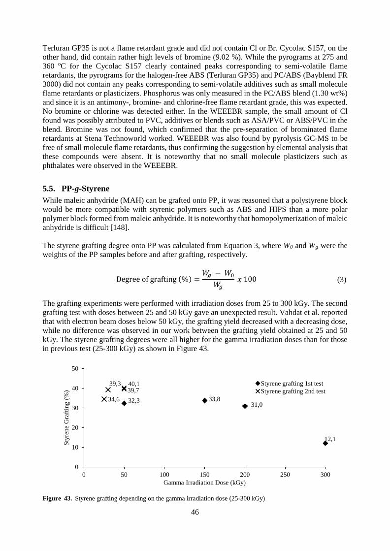
46
Terluran GP35 is not a flame retardant grade and did not contain Cl or Br. Cycolac S157, on the other hand, did contain rather high levels of bromine (9.02 %). While the pyrograms at 275 and 360 oC for the Cycolac S157 clearly contained peaks corresponding to semi-volatile flame retardants, the pyrograms for the halogen-free ABS (Terluran GP35) and PC/ABS (Bayblend FR 3000) did not contain any peaks corresponding to semi-volatile additives such as small molecule flame retardants or plasticizers. Phosphorus was only measured in the PC/ABS blend (1.30 wt%) and since it is an antimony-, bromine- and chlorine-free flame retardant grade, this was expected. No bromine or chlorine was detected either. In the WEEEBR sample, the small amount of Cl found was possibly attributed to PVC, additives or blends such as ASA/PVC or ABS/PVC in the blend. Bromine was not found, which confirmed that the pre-separation of brominated flame retardants at Stena Technoworld worked. WEEEBR was also found by pyrolysis GC-MS to be free of small molecule flame retardants, thus confirming the suggestion by elemental analysis that these compounds were absent. It is noteworthy that no small molecule plasticizers such as phthalates were observed in the WEEEBR.
5.5. PP-g-Styrene While maleic anhydride (MAH) can be grafted onto PP, it was reasoned that a polystyrene block would be more compatible with styrenic polymers such as ABS and HIPS than a more polar polymer block formed from maleic anhydride. It is noteworthy that homopolymerization of maleic anhydride is difficult [148]. The styrene grafting degree onto PP was calculated from Equation 3, where W0 and Wg were the weights of the PP samples before and after grafting, respectively.
The grafting experiments were performed with irradiation doses from 25 to 300 kGy. The second grafting test with doses between 25 and 50 kGy gave an unexpected result. Vahdat et al. reported that with electron beam doses below 50 kGy, the grafting yield decreased with a decreasing dose, while no difference was observed in our work between the grafting yield obtained at 25 and 50 kGy. The styrene grafting degrees were all higher for the gamma irradiation doses than for those in previous test (25-300 kGy) as shown in Figure 43.
Figure 43. Styrene grafting depending on the gamma irradiation dose (25-300 kGy)
32,3 33,831,0
12,1
34,6
39,339,740,1
0
10
20
30
40
50
0 50 100 150 200 250 300
Styr
ene
Gra
fting
(%)
Gamma Irradiation Dose (kGy)
Styrene grafting 1st testStyrene grafting 2nd test
Degree of grafting (%) =𝑊𝑊𝑔𝑔 − 𝑊𝑊0
𝑊𝑊𝑔𝑔 𝑥𝑥 100 (3)

47
In common with Vahdat et al., it was found, in general, that the grafting yield was independent of the gamma dose below 200 kGy [91]. In one of the grafting experiments (300 kGy), the amount of styrene grafted onto the polypropylene was smaller. In the majority of our experiments, approximately twice as much styrene was grafted onto the PP as was grafted by Vahdat et al. using a 50 to 200 kGy dose of fast electrons. While the irradiation of polypropylene in an acetylene atmosphere was reported to improve the mechanical properties of the plastic, no attempt was made to irradiate such a mixture, as acetylene is an explosive [149]. 5.5.1. Tensile Test The expected result with increasing ductility in terms of yield stress and stiffness with more styrene added turned out to be the opposite way. The elongation at break decreased more than threefold for both 5 and 20 wt% added PP-g-St and no yielding occurred, as shown in Figure 44. The difference was moderate, however, between the 5 and 20 wt% samples, both regarding the elongation at break and the Young’s modulus where 5 wt% grafting gave higher values. These results implied that the compatibility between the old and the new phase was poor. The curves are representative for each of the materials based on seven tested dog bones.
Figure 44. Stress versus strain curves (RT and 2.8 mm/min) for non-compatibilized virgin ternary blend (TBV) (reference) and TBV blended with styrene-grafted PP (PP-g-St, 5 and 20 wt%). The curves are representative for each of the tested materials based on seven test specimens. 5.5.2. Morphology on PP-g-Styrene Grafted TBV TBV with a 20 wt% addition of PP-g-St showed fewer white spots throughout the surface, depicted in Figure 45, than TBV with a 5 wt% addition of PP-g-St. These domains indicate agglomeration of the compatibilizer in the material giving low or no compatibilization between the phases, while Vahdat et al. found that the tensile strength of polypropylene fibres was decreased by irradiation, and grafting with styrene further decreased the tensile strength. They reasoned that the decrease in the strength of the polypropylene is caused by chain scission of the polypropylene. While they found that grafting with styrene was able to mitigate the adverse effect of the radiation on the mechanical properties of the PP, the grafted material was still weaker than the original plastic. In this work, even if the addition of the grafted material might have been able to slightly improve the mixing of the plastics, any such effect was offset by the reduction in the mechanical strength of the polypropylene caused by the irradiation process.
0
2
4
6
8
10
12
14
16
18
20
0,0 0,5 1,0 1,5 2,0 2,5 3,0 3,5 4,0 4,5 5,0
Stre
ss (M
Pa)
Strain (%)
TBV reference
TBV+PP-g-St 5 %
TBV+PP-g-St 20 %

48
The branches created by the treatment of the irradiated PP with styrene might have made the amorphous regions in the PP more brittle. This might have contributed to the reduction in the elongation at break [91]. As the addition of the graft copolymer had little if any effect on the Young’s modulus, it can be reasoned that the stiffer crystalline portions were unchanged by this addition.
Figure 45. Electron microscope images of the virgin ternary blend (TBV) reference (left), TBV with 5 wt% styrene-grafted PP (PP-g-St) (middle) and TBV with 20 wt% PP-g-St (right) 5.5.3. Drying of PP Pellets The results of the drying of the PP strips and granulate are shown in Table 22. It is clear that both the PP strips and granulate were dry and stable already after 15 minutes. This gave a 0.50 % decrease in weight for the strips and 0.35 % for the granulate showing that there is not much moisture in the material, which makes it suitable for grafting. Table 22. Drying of PP strips and PP granulate at 80 oC Time (minutes) PP Strips (g) PP Granulate (g)
0 19.93 20.02
15 19.82 19.91
30 19.82 19.94
45 19.80 19.91
75 19.82 19.94
225 19.83 19.95 5.5.4. FTIR The main peaks in both the FTIR spectra for virgin PP and 50 kGy gamma irradiated PP are the same, as shown in Figure 46. The carbonyl group (C=O) should be seen as a peak at 1700 cm-
1, which is an indicator of oxidative degradation of the polymer. This peak is not found in virgin PP or the 50 kGy gamma irradiated sample, indicating that very few carbonyl groups were formed. Thus, it can be concluded that the majority of the repeat units in the PP were unchanged.

49
Figure 46. FTIR spectra on virgin PP and 50 kGy gamma irradiated PP 5.6. WEEEBR Blended with Compatibilizer 5.6.1. Tensile Test The tensile tests on WEEEBR in combination with different amounts of compatibilizers showed a significant increase in ductility for the SEBS containing compatibilizers (G1652 E and FG1901 E), as shown in Figure 47. Even at as low as 2.5 wt% compatibilizer, the εb-values increased over five times. This is considerably higher than has previously been reported for PS/PP blends compatibilized by SEBS (up to 25 wt%) [109]. SEBS functionalized with MAH (FG1901 E) improved the εb-value more than three times (from 5 to 15-20 %). However, there did not seem to be a correlation between the increase in elongation and the amount of compatibilizer added (2.5 to 10 wt%).
Figure 47. Elongation at break measured for WEEEBR with the used compatibilizers and non-compatibilized WEEEBR (as reference). The error bars represent ± one standard deviation based on seven test samples.
60080010001200140016001800200022002400261028103010
Abs
orba
nce
Wavenumber (cm-1)
Virgin PP
PP 50 kGy
0
20
40
60
80
100
0 5 10 15 20
Elon
gatio
n at
Bre
ak (%
)
Fraction Compatibilizer (wt%)
SEBS (G1652 E)SEBS-g-MAH (FG1901 E)SAN+EPDM (Royaltuf)PP-g-MAH (Fusabond)WEEEBR Reference

50
As seen in Figure 48 and Figure 49, both the stiffness (σb) and the yield stress (σy) seemed to decrease with increasing amount of compatibilizer. The stiffness was lower than to the reference sample for all the compatibilized samples and appeared to have a linear dependency on the compatibilizer content. On the other hand, small compatibilizer levels (< 2.5 wt%) resulted in a slight decrease in yield stress but had very little influence on the σy-values between 2.5 and 20 wt%.
Figure 48. Tensile modulus of WEEEBR with the compatibilizers used and non-compatibilized WEEEBR. The error bars represent ± one standard deviation based on seven test samples.
Figure 49. Yield stress of WEEEBR with the compatibilizers used and non-compatibilized WEEEBR. The error bars represent ± one standard deviation based on seven test samples.
0
0,2
0,4
0,6
0,8
1
1,2
1,4
0 5 10 15 20
Tens
ile M
odul
us (G
Pa)
Fraction Compatibilizer (%)
SAN+EPDM (Royaltuf)PP-g-MAH (Fusabond)SEBS-g-MAH (FG1901 E)SEBS (G1652 E)WEEEBR Reference
0
5
10
15
20
25
30
35
0 5 10 15 20
Yie
ld S
tress
(MPa
)
Fraction Compatibilizer (%)
SAN+EPDM (Royaltuf)
PP-g-MAH (Fusabond)
SEBS-g-MAH (FG1901 E)
SEBS (G1652 E)
WEEEBR Reference

51
Figure 50. Tensile stress versus strain for the studied non-compatibilized WEEEBR (reference) and compatibilized WEEEBR samples It is clear that the addition of the SEBS compatibilizer greatly improved the mechanical properties of the WEEEBR, going from a brittle (non-compatibilized) to a ductile (compatibilized) material, as shown in Figure 50. Normally, an increase in toughness is associated with a loss in stiffness and strength [105], but in this case the loss in yield stress as well as stiffness are considered small, as illustrated in Figure 48 and Figure 49. At least two explanations exist for this improving effect of the SEBS. Firstly, the SEBS are a block copolymer with sections that are similar, and thus compatible, to the two types of polymers (polystyrene and polypropylene) in the blend. These can act as a surface-active material, which reduces the surface tension between the two liquid phases during processing [150]. Secondly, a reduction of the domain size can be expected to improve the properties of the mixture [151]. An alternative explanation offered by La Mantia is that the SEBS is not a true compatibilizer, instead it reduces the brittleness of at least one of the phases instead of accumulating at the interfaces [152]. 5.6.2. Impact Strength The impact strength positively increased with an increasing amount of compatibilizer for both notched and un-notched samples, which is shown in Table 23. For the notched samples, the impact strength increased by 28.6 % for the 2.5 wt% compatibilized sample, 81.0 % for the 5 wt% compatibilized sample and an astonishing 138.0 % for the 10 wt% compatibilized sample. The standard deviation is based on ten samples. Un-notched samples gave a higher standard deviation than notched samples, as could be expected. However, the impact strength of gamma irradiated samples decreased compared with the non-irradiated samples, though the compatibilizer showed a similar behaviour to that of the non-irradiated samples.
0
5
10
15
20
25
30
35
0 10 20 30 40 50 60 70 80 90
Tens
ile S
tress
(MPa
)
Strain (%)
WEEEBR Reference
G1652 E 1.25 wt%
G1652 E 5 wt%
G1652 E 10 wt%
G1652 E 20 wt%

52
Table 23. Impact testing of WEEEBR blended with the compatibilizer Kraton® G1652 E (0-10 wt%) and gamma irradiated samples (50 kGy)
Material Amount of Kraton®
G1652 E (wt%)
Notched Samples Un-notched Samples
kJ/m2 Standard Deviation kJ/m2 Standard
Deviation WEEEBR reference 0 2 0.3 8 1.0
WEEEBR 2.5 3 0.1 13 1.5
WEEEBR 5 4 0.3 17 2.0
WEEEBR 10 5 0.1 25 4.1
WEEEBR (50 kGy) 0 1 0.1 7 0.9
WEEEBR (50 kGy) 2.5 2 0.1 11 1.1
WEEEBR (50 kGy) 5 3 0.0 13 1.9
WEEEBR (50 kGy)* 0 2 0.5 8 1.1 *Gamma irradiated dog bones No change was seen in the mechanical properties of the gamma irradiated dog bones (same value as the WEEEBR reference). This effect could be due to hydroperoxides requiring thermal activation to form hydroxyl and alkoxy radicals [28]. The hydroxyl radicals abstract hydrogens at random sites to form new macromolecular radicals. The alkoxy radicals can undergo a beta-scission reaction to form a carbonyl group and a new but smaller macromolecular radical. This thermal activation of the hydroperoxides leading to chain scission has been specifically reported for polypropylene [100]. The aerobic gamma irradiation of PVC results in the formation of hydroperoxides, which later form these radicals [90]. Thus, the granules need to be gamma irradiated and then mechanically and thermally processed for a reaction resulting in a change of mechanical properties to occur. When moulding samples of WEEEBR were prepared for the impact test, it was noted that the injection moulding pressure increased with an increasing amount of compatibilizer. The increase was also smaller for the gamma irradiated samples; see Table 24. It was noted by Kallel et al. that the addition of SEBS to PE/PP and PE/PS mixtures increases the viscosity of the molten mixtures [150]. These observations indicated a viscosity decrease in the gamma irradiated blends. A decrease in the mechanical strength of one component in a composite material can cause the mechanical properties of the material taken as a whole to decrease. An example of this is polypropylene, which is known to be more sensitive to radiation than polystyrene [153] and to mainly undergo chain scission rather than crosslinking [154]. It can be reasoned that the loss of strength in the polypropylene domains can explain the effects of irradiation followed by thermal processing of the WEEEBR.

53
Table 24. The change of injection moulding pressures (bar) used for the WEEEBR blended with the compatibilizer Kraton® G1652 E (0-10 wt%)
Material Amount of
Kraton® G1652 E (%) Injection Moulding
Pressure (bar) Increase in Injection
Moulding Pressure (%)
WEEEBR reference 0 435 -
WEEEBR 2.5 508 17
WEEEBR 5 544 25
WEEEBR 10 544 25
WEEEBR (γ-irradiated granulate) 0 435 0
WEEEBR (γ-irradiated granulate) 2.5 471 8
WEEEBR (γ-irradiated granulate) 5 508 17 5.6.3. Dynamic Mechanical Thermal Analysis The DMTA results for storage modulus (G´) and loss tangent (tan δ) studied in compression mode for WEEEBR mixed with a different amount of the compatibilizer Kraton® G1652 E can be seen in Figure 51 and Figure 52. The storage moduli were about 1 GPa (room temperature, 22 oC), in compliance with previous results [155], and were fairly stable up to 85 oC. As expected from Figure 51, the storage modulus at temperatures below 85 oC was somewhat lower with an increasing amount of compatibilizer. It is interesting, however, to note that the compatibilizer does not seem to have any negative influence on the thermal stability, as no real difference in the softening (> 100 oC) of the materials can be seen between the reference and the compatibilized samples. The Tg can be found as the tan δ peak of WEEEBR and compatibilizer in Figure 52 at about 110 oC.
Figure 51. Storage modulus as a function of temperature for WEEEBR with 0-20 wt% compatibilizer
1,00E+07
1,00E+08
1,00E+09
1,00E+10
50 70 90 110 130 150
Stor
age
Mod
ulus
G´(
Pa)
Temperature (oC)
WEEEBR ReferenceWEEEBR+G1652 E 2.5 wt%WEEEBR+G1652 E 5 wt%WEEEBR+G1652 E 10 wt%WEEEBR+G1652 E 20 wt%

54
Figure 52. The loss tangent (tan δ) as a function of temperature for WEEEBR with 0-20 wt% compatibilizer 5.6.4. Melt Flow Rate on WEEEBR with Compatibilizer The MFR decreased with an increasing amount of compatibilizer for the WEEEBR, which is tabulated in Table 25. Thus the material became more viscous. This indicated better compatibility between the phases, which can be explained by better phase adhesion [156] and possibly co-continuous structures [157]. It is notable in Table 25 that the main decrease in MFR is seen between 0 and 2.5 wt% SEBS; a further increase in the compatibilizer amount only resulted in a slight decrease in MFR. This indicates that 2.5 wt% SEBS, or even less, is enough to significantly change the flow characteristics of the polymer blend and in should have a positive effect on the phase adhesion in the WEEEBR material. Gamma irradiation (50 kGy) was instead found to increase the MFR, which can be explained by a degradation of the polymer chains subjected to gamma irradiation, expectedly resulting in chain scission and decreased molecular weight. The increase in MFR with gamma irradiation was seen for all the different compatibilization amounts, compared with the non-irradiated samples, hence the viscosity decreased and the material flowed more easily. One measurement was made for each material. Table 25. Melt flow rate (g/10 minutes, 220 oC, 5 kg) of WEEEBR blended with the compatibilizer Kraton® G1652 E (0-10 wt%) and gamma irradiated samples (50 kGy). One measurement is done for each material.
Material Amount of Kraton®
G1652 E (wt%)
Melt Flow Rate (g/10 minutes), 220 oC, 5 kg
Non-irradiated 50 kGy Gamma Irradiated
WEEEBR reference 0 29 45
WEEEBR 2.5 21.7 38.2
WEEEBR 5 21.1 34
WEEEBR 10 19.6 -* * not measured
0
0,2
0,4
0,6
0,8
1
1,2
50 60 70 80 90 100 110 120 130 140 150
Loss
Tan
gent
(tan
δ)
Temperature (oC)
WEEEBR ReferenceWEEEBR+G1652 E 2.5 wt%WEEEBR+G1652 E 5 wt%WEEEBR+G1652 E 10 wt%WEEEBR+G1652 E 20 wt%

55
5.6.5. Morphology SEM-EDX images were taken of WEEEBR and compared with gamma irradiated (50 kGy) and non-irradiated WEEEBR (with and without 5 wt% Kraton® G1652 E) which can be seen in Figure 53 and Figure 54. Due to the high increase in ductility when the compatibilizer was added and the change in MFR between the samples, a visible change in morphology was expected. According to the literature, smaller domains and a more homogeneous structure in the material should have been seen [151]. Comparing the two images in Figure 54, however, only a moderate difference can be seen. The tensile testing experiment, Figure 50, strongly indicates that the addition of the compatibilizer increases the ductility of the plastic, though the appearance of the fracture is more similar to that expected for a brittle fracture than a ductile one. This failure to observe a ductile fracture could be due to the fact that the sample preparation fracturing for microscopy was faster than the fracturing process occurring during tensile testing. However, in Figure 54 the right image clearly suggests that the compatibilized plastic underwent a more ductile fracture than the non-compatibilized plastic. This result is in agreement with the tensile testing results obtained with a smaller test specimen, seen in Figure 50, made by punching an extruded plastic strip. The appearance of the fracture surface in Figure 54 (right) suggests the fracture was more ductile than that which occurred when the non-irradiated plastic was fractured, as seen in Figure 54 (left). One explanation is that the PP undergoes chain scission when it is irradiated with a dose of 50 kGy, causing the viscosity and Young’s modulus to decrease. This causes the fracturing process to be a more ductile type of fracture.
Figure 53. Electron microscope images (2600x magnification) of WEEEBR (left) and WEEEBR compatibilized with 5 wt% Kraton® G1652 E (right)

56
Figure 54. Electron microscope images (2600x magnification) of 50 kGy gamma irradiated WEEEBR (left) and 50 kGy gamma irradiated WEEEBR compatibilized with 5 wt% Kraton® G1652 E (right) The gamma irradiated sample with compatibilizer in Figure 54 (right) was slightly orientated, which the other samples were not. Whether this orientation was attributed to the cross-section fracture of the dog bone or an event from the injection moulding is difficult to say. The domain sizes for gamma irradiated samples and the non-irradiated samples were similar.

57
5.6.6. Differential Scanning Calorimetry (DSC) The DSC curves for WEEEBR (gamma irradiated and non-irradiated) and WEEEBR with 5 wt% Kraton® G1652 E compatibilizer are shown in Figure 55. The Tg was not easy to distinguish by DSC but was between 100 and 110 oC for all samples, which was also seen in the DMTA measurements of the tan δ peaks in Figure 52. Tm (melting temperature) was approximately 160-170 oC for WEEEBR, 155-165 oC for the gamma irradiated WEEEBR and 160-170 oC for WEEEBR with 5 wt% Kraton® G1652 E compatibilizer. The areas under the Tm peaks are similar, which indicates no major change in the crystallinity between the samples.
Figure 55. The heat flow curves (endothermic is upwards) from DSC showing the transition regions of WEEEBR. The heating rate was 10 oC min-1 in a nitrogen atmosphere. The relative heat flow was the same for all the curves, but the curves have been shifted along the y-axis. 5.6.7. Technical Data Sheet of WEEEBR Blended with 5 wt% Kraton® G1652 E The technical data sheet of WEEEBR blended with 5 wt% Kraton® G1652 E has been compiled in Table 26. It is notable that the processing conditions are almost the same for compatibilized and non-compatibilized WEEEBR. The tensile modulus is slightly lower than the WEEEBR shown in Table 12. The yield stress is similar but the big difference is in elongation at break between the compatibilized WEEEBR (22.8-35.6 %) and the WEEEBR (1.7-5.0 %). The other significant difference between the samples was the Charpy impact strength where the compatibilized WEEEBR was 3.3-4.1 compared with 1.6-2.3 kJ m2-1 for WEEEBR.
50 70 90 110 130 150 170 190
Rel
ativ
e H
eat F
low
Temperature (oC)
WEEEBRWEEEBR + 5 wt% G1652 EWEEEBR 50 kGy

58
Table 26. Technical data sheet of WEEEBR blended with 5 wt% Kraton® G1652 E Composition 95 wt% (HIPS (42 wt%), ABS (38 wt%), PP (10 wt%), remaining (10 wt%)) + compatibilizer Kraton® G1652 E (5 wt%) Processing information Value Unit
Extrusion temperature range 170-200 oC
Injection moulding temperature range 210-220 oC
Mould temperature 60 oC
Mechanical properties Value Unit
Tensile modulus 1.0-1.1 GPa
Yield stress 28-29 MPa
Elongation at break 22.8-35.6 %
Charpy impact strength 3.3-4.1 kJ/m2
Thermal properties Value Unit
Glass transition temperature (Tg) 100-110 oC
Melting peak temperature (Tm) 165-175 oC
Melt flow rate (220 oC, 5 kg) 21 g/10 minutes
Applications
EEE, cable reel

59
6. Conclusions In order to understand the properties of a plastic blend, and set up an accurate test plan for it, it was necessary to first do a proper composition study of the electronic waste plastics. The composition of the Stena 1 fraction (denoted WEEEBR after washing and melt-filtration) was studied by FTIR analysis of approximately 1200 flakes. It was concluded that the main constituents were styrene-based plastics (84 wt%) and polyolefins (12 wt%). Of the styrene-based plastics, the main part was PS/HIPS (42 wt%) followed by ABS (38 wt%). The polyolefins were mainly PP (10 wt%) and PE (1.5 wt%). An attempt was made to develop a leaching process to recover antimony from an ABS computer casing. A hot solution of sodium hydrogen tartrate in DMSO was used as the leaching medium. The leaching was shown to be successful and the leaching efficiency was almost 50 %. Virgin ABS can be recycled by re-melting, ageing and extrusion up to four times before the materials starts to degrade. It was not beneficial to subject the ABS to gamma irradiation before the repeated recycling and accelerated ageing nor between the recycling cycles to enhance the mechanical properties. The pyrolysis GC-MS of WEEEBR complemented with the ICP-OES and XPS results showed that no halogenated brominated flame retardants were present. Since there is a legal impediment to recycling plastics containing halogenated flame retardants, it is now clear that the separation method of bromine-containing plastics at Stena Technoworld was effective. It was also found that the pyrolysis GC-MS curves for 275, 360 and 500 oC, for non-irradiated and irradiated samples, showed evidence of debromination of a brominated flame retardant containing ABS (Cycolac S157). While radiation debromination of the flame retardant did occur, crosslinking made the plastic unsuitable for recycling. The hypothesis that gamma irradiation would enhance the mechanical properties of ABS and/or WEEEBR by creating free radicals in the polymer that would create small amounts of crosslinks was shown not to be true. It was found that the material became more brittle with an increased gamma irradiation dose. WEEEBR was a rather brittle material with low strength and ductility, but with the addition of a compatibilizer, Kraton® G1652 E, it was much more ductile. The elongation at break was increased over five times by the addition of as little as 2.5 wt% of the compatibilizer. Gamma irradiation on WEEEBR caused a decrease in viscosity with doses up to 100 kGy (indicated chain scissoring of the polymer) and with further irradiation, an increase in viscosity occurred. This indicates that crosslinking of the polymer chains dominates over the chain scissoring above 100 kGy. The impact strength test showed a decrease in the strength of gamma irradiated samples compared with non-irradiated samples. It was found that while irradiation of test specimens had little effect on the strength of the plastic, the irradiation of plastic granulate followed by extrusion and injection moulding caused a reduction in impact strength. WEEEBR and similar blends have the potential to be used as a replacement for virgin plastics when melt-blended, melt-filtrated and, especially, when low amounts of SEBS-containing compatibilizer has been added.

60

61
7. Future Work
• Further investigations of the viscosity changes are needed to understand what happens when the gamma irradiated WEEEBR blended with compatibilizer is injection moulded.
• More mechanical and rheological tests are needed on extruded test samples, though it is
well known that injection moulded test samples give better repeatable properties (lower standard deviation). It would be interesting to optimize the injection moulding settings, primarily for WEEEBR alone and then blended with a compatibilizer.
• In the studied WEEE plastics fraction (Stena 1), the main constituents were ABS, HIPS
and PP. In different fractions, investigated by others, PC/ABS, for example, has been found in larger quantities. It would be very interesting to change the fraction proportions and introduce other plastics together with the compatibilizer to see where the limits are to retain the same mechanical and thermal properties.
• Other compatibilizers could be tested for even better compatibility between the plastics
within WEEEBR and morphology studies by microscopy.

62

63
8. Acknowledgement I would like to thank… my main supervisor Mark Foreman for sharing so much knowledge with me within the field of chemistry, caring about my work and well-being and, of course, the enjoyable discussions about having children of the same age. my co-supervisor Antal Boldizar for your support and for sharing knowledge with me over the years. my examiner Christian Ekberg for believing in me and allowing me to do it my way. Britt-Marie Steenari for doing a great job with the research school POWRES so we could make interesting study trips and visit conferences. my twin PhD student Erik Stenvall. We made it! Thank you for being supportive and innovative all the time! Bart van Dongen for providing pyrolysis GC-MS data and Kristina Karlsson for the DSC help. the companies that have been interested in and supported the research: Stena Metall, Axjo Plastic, Renova, Sims Recycling, Swerea IVF and SP. Chalmers Area of Advance, Materials Science, for funding my work. my colleagues, former and present, at Industrial Materials Recycling/Nuclear Chemistry and Materials and Manufacturing Technology for all your help and for making it so much fun to go to work! my roommates Lovisa and Artem. Lovisa, I am truly impressed and inspired by you. You rock bigtime! Artem my Russian friend, I am thankful for our talks and all that you have taught me, especially about Russia. my husband Martin, my solid rock and great love in life, for giving me this opportunity. We have made a fantastic journey together so far: now, we begin yet another chapter. my lovely children Emilia and Alexander. You have been small researchers all your lives, on your own and with mummy at work, hanging in a baby carrier on my stomach or sleeping in your pram. my mother, Mariann, for always knowing that I would do ‘big things’ (when I might have doubted it sometimes) and my late father, Roy, for encouraging me to learn as much as I possibly could and also taught me to ‘arbeta alltid i rätt tid’ (don’t put off until tomorrow what you can do today). my friends outside the academic world who are always there year after year, even if there are literally years between us meeting in person. Sandra Tostar Gothenburg, January 2016

64

65
9. List of Abbreviations ABS Acrylonitrile-butadiene-styrene copolymer ABS/PC Acrylonitrile-butadiene-styrene copolymer/polycarbonate AMU Atomic mass unit BFR Brominated flame retardant CaCO3 Calcium carbonate DMSO Dimethyl sulfoxide DMTA Dynamic mechanical thermal analysis DSC Differential scanning calorimetry E (E’) Modulus of elasticity (Storage Modulus) EEE Electrical and electronic equipment ELV End-of-life vehicles EPDM Ethylene-propylene-non-conjugated-diene elastomers EPR Extended producer responsibility EU European Union FTIR Fourier transform infrared spectroscopy HDPE High density polyethylene HIPS High impact polystyrene ICP-OES Inductively coupled plasma optical emission spectroscopy IM Injection moulding LDPE Low density polyethylene MAH Maleic anhydride MeV Megaelectron volt PA Polyamide PBB Polybrominated biphenyl PBDD/F Polybrominated dioxins and furans PBDE Polybrominated diphenyl ether PBT Poly(butylene terephthalate) PC Polycarbonate PE Polyethylene PET Poly(ethylene terephthalate) POM Polyoxymethylene POP Persistent organic pollutant PP Polypropylene PPO Poly(p-phenylene oxide) PS Polystyrene PUR Polyurethane PVC Polyvinylchloride RoHS Restriction of the use of certain hazardous substances in EEE SAN Styrene-acrylonitrile Sb Antimony SBS Styrene-butadiene-styrene copolymer SEBS Styrene-b(ethylene-co-butylene)-b-styrene copolymer SEM-EDX Scanning electron microscopy with energy dispersive X-ray spectroscopy SMMA Styrene methyl methacrylate SSE Single screw extrusion sWEEE Small WEEE ῡ Antineutrino β- Electron

66
β+ Positron Tβ Secondary relaxation transition Tg Glass transition temperature Tox Thermo-oxidative degradation temperature tan δ Loss tangent TBBPA Tetrabromobisphenol A TBR Recycled ternary blend TBV Virgin ternary blend TSE Twin screw extrusion u Unified atomic mass unit WEEE Waste electrical and electronic equipment WEEEBR WEEE plastics blend of recycled materials wt% Weight % γ Gamma ray ΔGmix Change in Gibb’s free energy of mixing ΔHmix Change in heat of mixing ΔSmix Change in entropy of mixing εb Elongation at break εy Elongation at yield σ Stress σb Stress at break σy Yield stress

67
10. References 1. Mancini, L., De Camillis, C., Pennington, D., (eds.), Security of supply and scarcity of raw
materials. Towards a methodological framework for sustainability assessment.; Publications Office of the European Union: Luxembourg, 2013; pp 24-27, 39-42.
2. Scott, G. Environmental impact of polymers. In Polymers and the Environment; The Royal Society
of Chemistry: 1999; pp. 19-37. 3. Menikpura, S. N. M., Santo, A., Hotta, Y., Assessing the climate co-benefits from Waste Electrical
and Electronic Equipment (WEEE) recycling in Japan. Journal of Cleaner Production, 2014, 74, 183-190.
4. Kiddee, P., Naidu, R., Wong, M. H., Electronic waste management approaches: An overview.
Waste Management, 2013, 33, 1237-1250. 5. Buekens, A., Yang, J., Recycling of WEEE plastics: a review. Journal of Material Cycles and
Waste Management, 2014, 16, 415-434. 6. 2012/19/EU, Directive 2012/19/EU of the European Parliament and of the Council of 4 July 2012
on waste electrical and electronic equipment (WEEE). In 2012. 7. Plastics Europe, Plastics - The facts 2014/2015; 2015; pp 1-34. 8. European Commission DG Environment, Plastic waste in the environment; April, 2011. 9. Kumar, A., Pastore, P., Lead and cadmium in soft plastic toys. Current Science, 2007, 93, 818-
822. 10. El-Kretsen, Framtagande av schablon för 2015; 2015. 11. Wang, D., Xie, X.-M., Novel strategy for ternary polymer blend compatibilization. Polymer, 2006,
47, 7859-7863. 12. Halimatudahliana, Ismail, H., Nasir, M., The effect of various compatibilizers on mechanical
properties of polystyrene/polypropylene blend. Polymer Testing, 2002, 21, 163-170. 13. Wang, D., Li, Y., Xie, X.-M., Guo, B.-H., Compatibilization and morphology development of
immiscible ternary polymer blends. Polymer, 2011, 52, 191-200. 14. Waste & Resources Action Programme, Separation of mixed WEEE plastics final report (WRAP
Project MDD018 and MDD023); 2009. 15. Puckett, J., Byster, L., Westervelt, S., Gutierrez, R., Davis, S., Hussain, A., Dutta, M., Exporting
harm, the high-tech trashing of Asia; Basel Action Network and Silicon Valley Toxics Coalition: 2002.
16. Sinha, D. The management of electronic waste: A comparative study on India and Switzerland.
University of St Gallen: Gallen, Switzerland, 2004. 17. Greenpeace, The e-waste problem. Available
online: www.greenpeace.org/international/campaigns/toxics/electronics/the-e-waste-problem# (2015-09-18).
18. Vats, M. C., Singh, S. K., E-Waste characteristic and its disposal. International Journal of

68
Ecological Science and Environmental Engineering, 2014, 1, 49-61. 19. Ongondo, F. O., Williams, I. D., Cherrett, T. J., How are WEEE doing? A global review of the
management of electrical and electronic wastes. Waste Management, 2011, 31, 714-730. 20. Betts, K., Reducing the global impact of e-waste. Environmental Science & Technology, 2008, 42,
1393-1393. 21. Robinson, B. H., E-waste: An assessment of global production and environmental impacts.
Science of The Total Environment, 2009, 408, 183-191. 22. J.D. Power and Associates, U.S. Wireless Mobile Phone Evaluation Study; 2007. 23. El-Kretsen, Environmental sustainability shall be easy; 2014; p 3. 24. El-Kretsen, El-Kretsen Verksamheten 2014; 2014. 25. Waeger, P. A., Hischier, R., Life cycle assessment of post-consumer plastics production from waste
electrical and electronic equipment (WEEE) treatment residues in a Central European plastics recycling plant. Science of the Total Environment, 2015, 529, 158-167.
26. Ramesh, V., Biswal, M., Mohanty, S., Nayak, S. K., Recycling of engineering plastics from waste
electrical and electronic equipments: influence of virgin polycarbonate and impact modifier on the final performance of blends. Waste management & research : the journal of the International Solid Wastes and Public Cleansing Association, ISWA, 2014, 32, 379-388.
27. Naturvårdsverket, Recycling and disposal of electronic waste- Health hazards and environmental
impacts; 6417; CM gruppen: Stockholm, 2011; pp 13, 36-55. 28. Delgado, C., Barruetabeña, L., Salas, O., Assessment of the environmental advantages and
drawbacks of existing and emerging polymers recovery processes; European Commission, 2007. 29. Menad, N., Björkman, B., Allain, E. G., Combustion of plastics contained in electric and electronic
scrap. Resources, Conservation and Recycling, 1998, 24, 65-85. 30. Taurino, R., Pozzi, P., Zanasi, T., Facile characterization of polymer fractions from waste
electrical and electronic equipment (WEEE) for mechanical recycling. Waste Management, 2010, 30, 2601-2607.
31. Dimitrakakis, E., Janz, A., Bilitewski, B., Gidarakos, E., Small WEEE: Determining recyclables
and hazardous substances in plastics. Journal of Hazardous Materials, 2009, 161, 913-919. 32. Martinho, G., Pires, A., Saraiva, L., Ribeiro, R., Composition of plastics from waste electrical and
electronic equipment (WEEE) by direct sampling. Waste Management, 2012, 32, 1213-1217. 33. Vilaplana, F., Karlsson, S., Quality concepts for the improved use of recycled polymeric materials:
A review. Macromolecular Materials and Engineering, 2008, 293, 274-297. 34. Link, T., Improving Plastic Management in Delhi- A report on WEEE plastic recycling; 2011. 35. Freegard, K., Tan, G., Morton, R., Develop a process to separate brominated flame retardants
from WEEE polymers; Waste Resources Action Programme: Banbury, 2006. 36. Wäger, P. A., Böni, H., Buser, A., Morf, L., Schluep, M., Streicher, M. In Recycling of plastics
from Waste Electrical and Electronic Equipment (WEEE) - Tentative results of a Swiss study, R´09 World Congress, Davos, Switzerland, 2009; Davos, Switzerland, 2009.

69
37. Stenvall, E., Tostar, S., Boldizar, A., Foreman, M. R. S. J., Moller, K., An analysis of the composition and metal contamination of plastics from waste electrical and electronic equipment (WEEE). Waste Management, 2013, 33, 915-922.
38. Maris, E., Botane, P., Wavrer, P., Froelich, D., Characterizing plastics originating from WEEE: A
case study in France. Minerals Engineering, 2015, 76, 28-37. 39. 2011/65/EU, Directive 2011/65/EU of the European Parliament and of the Counsil of 8 June 2011
on the restriction of the use of certain hazardous substances in electrical and electronic equipment (RoHS). In 2011.
40. McElroy, J. A., Shafer, M. M., Trentham-Dietz, A., Hampton, J. M., Newcomb, P. A., Cadmium
exposure and breast cancer risk. Journal of the National Cancer Institute, 2006, 98, 869-873. 41. Wetterhahn, K. E., Hamilton, J. W., Molecular-basis of hexavalent chromium carcinogenicity -
effect on gene-expression. Science of the Total Environment, 1989, 86, 113-129. 42. Taylor, J. R., Neurotoxicity of certain environmental substances. Clinics in Laboratory Medicine,
1984, 4, 489-497. 43. 2015/863, Commission delegated directive (EU) 2015/863 of 31 March 2015; 2015. 44. Directive 2002/95/EC Restriction of Hazardous Substances (RoHS); 2011. 45. National Food Agency Sweden, Market Basket 2010- chemical analysis, exposure estimation and
health-related assessment of nutrients and toxic compounds in Swedish food baskets; Rapport nr 7; 2012; p 30.
46. Schecter, A. Dioxins and health: including other persistent organic pollutants and endocrine
disruptors; John Wiley & Sons: Hoboken, N.J, 2012; Vol. 3rd. 47. de Boer, J., de Boer, K., Boon, J. P. Polybrominated biphenyls and diphenylethers. In Volume 3
Anthropogenic Compounds Part K; Springer: 2000; pp. 61-96. 48. Birnbaum, L. S., Morrissey, R. E., Harris, M. W., Teratogenic effects of 2,3,7,8-
tetrabromodibenzo-p-dioxin and three polybrominated dibenzofurans in C57BL6N mice. Toxicology and Applied Pharmacology, 1991, 107, 141-152.
49. Patnaik, P. A comprehensive guide to the hazardous properties of chemical substances; John Wiley
& Sons, Inc.: Hoboken, NJ, USA, 2007; Vol. 3rd. 50. Hansen, H. R., Pergantis, S. A., Detection of antimony species in citrus juices and drinking water
stored in PET containers. J. Anal. At. Spectrom., 2006, 21, 731-733. 51. Shotyk, W., Krachler, M., Chen, B., Contamination of Canadian and European bottled waters
with antimony from PET containers. Journal of Environmental Monitoring, 2006, 8, 288-292. 52. European Commission, Report of the Ad-hoc Working Group on defining critical raw materials;
Brussels, 2010; p 84. 53. Boyle, R. W., Jonasson, I. R., The geochemistry of antimony and its use as an indicator element
in geochemical prospecting. Journal of Geochemical Exploration, 1984, 20, 223-302. 54. European Commission, Annex V to the Report of the Ad-hoc Working Group on defining critical
raw materials; Brussels, 2010; pp 7-11.

70
55. Walding, M., Konsekvensbeskrivning - till föreskrifterna om hygieniska gränsvärden AFS 2011:18; 2012; pp 11-13.
56. Riess, M., Ernst, T., Popp, R., Muller, B., Thoma, H., Vierle, O., Wolf, M., van Eldik, R., Analysis
of flame retarded polymers and recycling materials. Chemosphere, 2000, 40, 937-941. 57. About.com, History of plastic recycling. Available
online: http://composite.about.com/od/Plastics/a/Recycling-Plastics.htm (2015-10-19). 58. Banerjee, R., Importance of recycling. International Journal of Innovative Research in Electrical,
Electronics, Instrumentation and Control Engineering, 2015, 3, 53-55. 59. Zebrowski, C., A product with legs. America in WWII, 2005. 60. ISO 15270:2008 Plastics - Guidelines for the recovery and recycling of plastics waste;
International Organization for Standardization: 2008. 61. Hopewell, J., Dvorak, R., Kosior, E., Plastics recycling: challenges and opportunities.
Philosophical Transactions of the Royal Society of London B: Biological Sciences, 2009, 364, 2115-2126.
62. Mudgal, S., Lyons, L., Kong, M. A., Study on an increased mechanical recycling target for
plastics, Final report prepared for Plastics Recyclers Europe; Bio Intelligence Service: 2013. 63. Schlummer, M., Gruber, L., Mäurer, A., Wolz, G., van Eldik, R., Characterisation of polymer
fractions from waste electrical and electronic equipment (WEEE) and implications for waste management. Chemosphere, 2007, 67, 1866-1876.
64. Klason, C., Kubát, J., Boldizar, A., Rigdahl, M. Plaster- materialval och materialdata; 6th ed.;
Liber: Uppsala, 2004. 65. Pongstabodee, S., Kunachitpimol, N., Damronglerd, S., Combination of three-stage sink–float
method and selective flotation technique for separation of mixed post-consumer plastic waste. Waste Management, 2008, 28, 475-483.
66. Chrisochoou, A., Dufour, D., Styrenic copolymers; Shropshire, United Kingdom, 2002; pp 28-28. 67. Menad, N., Guignot, S., van Houwelingen, J. A., New characterisation method of electrical and
electronic equipment wastes (WEEE). Waste Management, 2013, 33, 706-713. 68. Lazarevic, D., Aoustin, E., Buclet, N., Brandt, N., Plastic waste management in the context of a
European recycling society: Comparing results and uncertainties in a life cycle perspective. Resources, Conservation and Recycling, 2010, 55, 246-259.
69. Linnenkoper, K., Plastics recyclers fighting to stay alive. Recycling International, 2015, 3. 70. Thomas Weissenbach, Reisinger, H., Read, B., Schneider, J., Plastic waste; Brussels, 2013; p 7. 71. Bartelings, H., van Beukering, P., Kuik, O., Linderhof, V., Oosterhuis, F., Brander, L.,
Wagtendonk, A., Effectiveness of landfill taxation; R-05/05: Institute for Environmental Studies: Amsterdam, 2005.
72. Villanueva, A., Eder, P., End of waste criteria for waste plastic conversion; European Commission
Joint Research Centre Institute for Prospective Technological Studies: Luxembourg, 2014. 73. Statutory instrument 2013/3113: The waste electrical and electronic equipment regulations; The

71
Stationary Office Limited: Norwich, 2013. 74. Naturvårdsverket, A strategy for sustainable waste management; Stockholm, 2005; p 17. 75. Hamos, Electrostatic separation technologies; pp 16-17. 76. Kiong, C. In WEEE-plastic recycling system – hamos KRS, Electronics Recycling Asia, Singapore,
2015; Singapore, 2015. 77. Wu, G., Li, J., Xu, Z., Triboelectrostatic separation for granular plastic waste recycling: A review.
Waste Management, 2013, 33, 585-597. 78. Nelson, W. R. Interference handbook; Second ed.; Radio Publications Inc.: USA, 1990. 79. Charlesby, A. Atomic Radiation and Polymers: International Series of Monographs on Radiation
Effects in Materials; Elsevier: 2013; Vol. 1. 80. Park, J.-N., Sung, N.-Y., Byun, E.-H., Byun, E.-B., Song, B.-S., Kim, J.-H., Lee, K.-A., Son, E.-
J., Lyu, E.-S., Microbial analysis and survey test of gamma-irradiated freeze-dried fruits for patient's food. Radiation Physics and Chemistry, 2015, 111, 57-61.
81. Choppin, G., Liljenzin, J.-O., Rydberg, J., Ekberg, C. Chapter 1 - Origin of Nuclear Science. In
Radiochemistry and Nuclear Chemistry (Fourth Edition); Academic Press: Oxford, 2013; pp. 1-13.
82. Choppin, G., Liljenzin, J.-O., Rydberg, J., Ekberg, C. Chapter 5 - Unstable Nuclei and Radioactive
Decay. In Radiochemistry and Nuclear Chemistry (Fourth Edition); Academic Press: Oxford, 2013; pp. 85-123.
83. Choppin, G., Liljenzin, J.-O., Rydberg, J., Ekberg, C. Chapter 2 - Elementary Particles. In
Radiochemistry and Nuclear Chemistry (Fourth Edition); Academic Press: Oxford, 2013; pp. 15-30.
84. Choppin, G., Liljenzin, J.-O., Rydberg, J., Ekberg, C. Chapter 7 - Absorption of Nuclear Radiation.
In Radiochemistry and Nuclear Chemistry (Fourth Edition); Academic Press: Oxford, 2013; pp. 163-208.
85. Hassan, M. M., Mechanical, thermal, and morphological behavior of the polyamide
6/acrylonitrile-butadiene-styrene blends irradiated with gamma rays. Polymer Engineering and Science, 2008, 48, 373-380.
86. Clegg, D. W., Collyer, A. A. Irradiation Effects on Polymers; Springer: 1991. 87. Swallow, A. J., Radiation Chemistry of Organic Compounds Pergamon Press: Oxford, New York,
1960; p. 380. 88. Morrison, R. T., Boyd, R. N. Organic Chemistry, (1987); Allyn and Bacon: Newton,
Massachusetts, p. 637. 89. Schuler, R. H., Wojnarovits, L., Radical yields in the radiolysis of branched hydrocarbons:
Tertiary C-H bond rupture in 2,3-dimethylbutane, 2,4-dimethylpentane, and 3-ethylpentane. Journal of Physical Chemistry A, 2003, 107, 9240-9247.
90. Colombani, J., Labed, V., Joussot-Dubien, C., Perichaud, A., Raffi, J., Kister, J., Rossi, C., High
doses gamma radiolysis of PVC: Mechanisms of degradation. Nuclear Instruments & Methods in Physics Research Section B-Beam Interactions with Materials and Atoms, 2007, 265, 238-244.

72
91. Vahdat, A., Bahrami, H., Ansari, N., Ziaie, F., Radiation grafting of styrene onto polypropylene fibres by a 10 MeV electron beam. Radiation Physics and Chemistry, 2007, 76, 787-793.
92. Rao, T. P., Praveen, R. S., Daniel, S., Styrene-divinyl benzene copolymers: Synthesis,
characterization, and their role in inorganic trace analysis. Critical Reviews in Analytical Chemistry, 2004, 34, 177-193.
93. Wanka, G., Hoffmann, H., Ulbricht, W., The aggregation behavior of poly-(oxyethylene)-poly-
(oxypropylene)-poly-(oxyethylene)-block-copolymers in aqueous-solution. Colloid and Polymer Science, 1990, 268, 101-117.
94. Brown, W. H., Rogers, E. P. General, organic, and biochemistry; Brocks/Cole: 1987. 95. Wasserman, E., The preparation of interlocking rings - a catenane. Journal of the American
Chemical Society, 1960, 82, 4433-4434. 96. Arimoto, H., Ishibash.M, Hirai, M., Chatani, Y., Crystal structure of gamma-form of nylon 6.
Journal of Polymer Science Part a-General Papers, 1965, 3, 317-326. 97. Bhattacharya, A., Misra, B. N., Grafting: a versatile means to modify polymers: Techniques,
factors and applications. Progress in Polymer Science, 2004, 29, 767-814. 98. Dorff, G., Hahn, M., Laschewsky, A., Lieske, A., Optimization of the property profile of poly-L-
lactide by synthesis of PLLA-polystyrene-block copolymers. Journal of Applied Polymer Science, 2013, 127, 120-126.
99. Fink, J. K. Chapter 18 - Grafting. In Reactive Polymers Fundamentals and Applications (Second
Edition); William Andrew Publishing: Oxford, 2013; pp. 425-452. 100. Scott, G. Environmental stability of polymers. In Polymers and the Environment; The Royal
Society of Chemistry: 1999; pp. 38-67. 101. Flynn, J. H. Chapter 14 - Polymer degradation. In Handbook of Thermal Analysis and Calorimetry;
Elsevier Science B.V.: 2002; Vol. Volume 3, pp. 587-651. 102. Hawkins, W., Thermal and oxidative degradation of polymers. Polymer Engineering & Science,
1964, 4, 187-192. 103. Tarantili, P. A., Mitsakaki, A. N., Petoussi, M. A., Processing and properties of engineering
plastics recycled from waste electrical and electronic equipment (WEEE). Polymer Degradation and Stability, 2010, 95, 405-410.
104. Pospıš́il, J., Horák, Z., Kruliš, Z., Nešpůrek, S., Kuroda, S.-i., Degradation and aging of polymer
blends I. Thermomechanical and thermal degradation. Polymer Degradation and Stability, 1999, 65, 405-414.
105. Utracki, L. A. Polymer Blends Handbook; Kluwer Academic Publishers: Dordrecht, The
Netherlands, 2014; Vol. 1st. 106. Struik, L. C. E., Physical aging in plastics and other glassy materials. Polymer Engineering and
Science, 1977, 17, 165-173. 107. Harvey, J. A. Chemical and physical aging of plastics-Chapter 7. In Handbook of Environmental
Degradation of Materials; William Andrew Publishing: 2005; pp. 153-163. 108. Gedde, U. W. Polymer physics; Chapman & Hall: London, 1995; Vol. 1.

73
109. Sani Amril, S., Hassan, A., Mokhtar, M., Syed Mustafa Syed, J., Effect of SEBS on the mechanical properties and miscibility of polystyrene rich polystyrene/polypropylene blends. Progress in Rubber, Plastics and Recycling Technology, 2005, 21, 261-276.
110. Giudice, L. D., Cohen, R. E., Attalla, G., Bertinotti, F., Compatibilizing effect of a diblock
copolymer of isotactic polystyrene and isotactic polypropylene in blends of the corresponding homopolymers. Journal of Applied Polymer Science, 1985, 30, 4305-4318.
111. Sperling L. H. Introduction to physical polymer science; John Wiley & Sons, Inc.: New Jersey,
2006; Vol. 4th. 112. Koning, C., Van Duin, M., Pagnoulle, C., Jerome, R., Strategies for compatibilization of polymer
blends. Progress in Polymer Science, 1998, 23, 707-757. 113. Bruder, F., Brenn, R., Stuhn, B., Strobl, G. R., Interdiffusion in the partially miscible polymer
blend of deuterated polystyrene and poly(styrene-co-bromostyrene). Macromolecules, 1989, 22, 4434-4437.
114. Brandrup, J., Immergut, E. H., Grulke, E. A. Polymer handbook; Wiley: New York, 1999; Vol. 4. 115. Thomas, S., Shanks, R., Chandrasekharakutup, S. Nanostructured polymer blends; Elsevier
Science and Technology Books, Inc.: Oxford, United Kingdom, 2014. 116. Fricke, H., Hart, E. J., Chemical dosimetry. Radiation dosimetry, 1966, 2, 167-239. 117. Khan, H., Anwar, M., Stability of response of the ferrous-cupric sulfate dosimeter at different
temperatures. Journal of radioanalytical and nuclear chemistry, 1993, 175, 199-206. 118. Gerlach, R. W., Dobb, D. E., Raab, G. A., Nocerino, J. M., Gy sampling theory in environmental
studies. 1. Assessing soil splitting protocols. Journal of Chemometrics, 2002, 16, 321-328. 119. Hall, W. J., Williams, P. T., Analysis of products from the pyrolysis of plastics recovered from the
commercial scale recycling of waste electrical and electronic equipment. Journal of Analytical and Applied Pyrolysis, 2007, 79, 375-386.
120. Morf, L. S., Tremp, J., Gloor, R., Schuppisser, F., Stengele, M., Taverna, R., Metals, non-metals
and PCB in electrical and electronic waste – Actual levels in Switzerland. Waste Management, 2007, 27, 1306-1316.
121. Giles, H. F. J., Wagner, J. R. J., Mount, E. M. I. Extrusion - the definitive processing guide and
handbook; William Andrew Publishing: New York, 2005. 122. Bach, C., Dauchy, X., Chagnon, M.-C., Etienne, S., Chemical compounds and toxicological
assessments of drinking water stored in polyethylene terephthalate (PET) bottles: A source of controversy reviewed. Water Research, 2012, 46, 571-583.
123. Gress, M. E., Jacobson, R. A., X-ray and white radiation neutron-diffraction studies of optically-
active potassium antimony tartrate, K2Sb2(d-C4H2O6)2 2 H2O (tartar emetic). Inorganica Chimica Acta, 1974, 8, 209-217.
124. Hartley, D. W., Smith, G., Sagatys, D. S., Kennard, C. H. L., Antimony(III) Complexes With
Carboxylic-acids. 2. Preparation and crystal-structures of [Sb2Ag2(C6H6O7)4]and [SbNa(C6H6O7)2(H2O)2].H2O [C6H6O7 = Citrate(2-)]. Journal of the Chemical Society-Dalton Transactions, 1991, 2735-2739.
125. Bohaty, L., Frohlich, R., Tebbe, K. F., Crystallography of the antimony tartrates of calcium,

74
strontium and barium. Zeitschrift Fur Kristallographie, 1982, 159, 21-22. 126. Demertzis, P. G., Franz, R., Welle, F., The effects of gamma-irradiation on compositional changes
in plastic packaging films. Packaging Technology and Science, 1999, 12, 119-130. 127. Jafari, A. J., Donaldson, J. D., Determination of HCl and VOC emission from thermal degradation
of PVC in the absence and presence of copper, copper(II) oxide and copper(II) chloride. E-Journal of Chemistry, 2009, 6, 685-692.
128. Heys, H. L. Chemistry experiments at home for boys and girls; George G. Harrap & Company ltd:
London, 1959. 129. Tamaddon, F., Hogland, W., Review of cadmium in plastic waste in Sweden. Waste Management
& Research, 1993, 11, 287-295. 130. Shawaphun, S., Manangan, T., Wacharawichanant, S. Thermo- and Photo- Degradation of LDPE
and PP Films Using Metal Oxides as Catalysts. In Functionalized and Sensing Materials; 2010; Vol. 93-94, pp. 505-508.
131. Yang, R., Christensen, P., Egerton, T., White, J., Degradation products formed during UV
exposure of polyethylene–ZnO nano-composites. Polymer Degradation and Stability, 2010, 95, 1533-1541.
132. Colin, X., Audouin, L., Verdu, J., Rozental-Evesque, M., Rabaud, B., Martin, F., Bourgine, F.,
Aging of polyethylene pipes transporting drinking water disinfected by chlorine dioxide. Part II-lifetime prediction. Polymer Engineering and Science, 2009, 49, 1642-1652.
133. Pticek, A., Hrnjak-Murgic, Z., Jelenccic, J., Mlinac-Misak, M., Morphology and thermal
behaviour of SAN/EPDM blends. Express Polymer Letters, 2007, 1, 370-377. 134. Fox, T. G., Flory, P. J., The glass temperature and related properties of polystyrene - influence of
molecular weight. Journal of Polymer Science, 1954, 14, 315-319. 135. Morf, L. S., Tremp, J., Gloor, R., Huber, Y., Stengele, M., Zennegg, M., Brominated flame
retardants in waste electrical and electronic equipment: substance flows in a recycling plant. Environmental Science & Technology, 2005, 39, 8691-8699.
136. Onwudili, J. A., Williams, P. T., Degradation of brominated flame-retarded plastics (Br-ABS and
Br-HIPS) in supercritical water. The Journal of Supercritical Fluids, 2009, 49, 356-368. 137. Boerrigter, H., Oudhuis, A. B. J., Tange, L., Bromine recovery from the plastics fraction of waste
of electrical and electronic equipment (WEEE) with staged gasification; Energy research Centre of the Netherlands (ECN): 2002.
138. Perraud, S., Vallat, M.-F., David, M.-O., Kuczynski, J., Network characteristics of hydrogenated
nitrile butadiene rubber networks obtained by radiation crosslinking by electron beam. Polymer Degradation and Stability, 2010, 95, 1495-1501.
139. Hoo Fatt, M. S., Ouyang, X., Three-dimensional constitutive equations for Styrene Butadiene
Rubber at high strain rates. Mechanics of Materials, 2008, 40, 1-16. 140. Pereira, C., Gil, L., Carriço, L., Reduction of the 2,4,6-trichloroanisole content in cork stoppers
using gamma radiation. Radiation Physics and Chemistry, 2007, 76, 729-732. 141. Arbon, R. E., Mincher, B. J., Knighton, W. B., Gamma-ray destruction of PCBs in isooctane and
transformer oil. Environmental Science & Technology, 1996, 30, 1866-1871.

75
142. Jung, S.-H., Kim, S.-J., Kim, J.-S., The influence of reaction parameters on characteristics of pyrolysis oils from waste high impact polystyrene and acrylonitrile–butadiene–styrene using a fluidized bed reactor. Fuel Processing Technology, 2013, 116, 123-129.
143. Sun, H., Rosenthal, C., Schmidt, L. D., Oxidative pyrolysis of polystyrene into styrene monomers
in an autothermal fixed-bed catalytic reactor. Chemsuschem, 2012, 5, 1883-1887. 144. Boldizar, A., Möller, K., Degradation of ABS during repeated processing and accelerated ageing.
Polymer Degradation and Stability, 2003, 81, 359-366. 145. Acierno, D., La Mantia, F., Titomanlio, G., Calderaro, E., Castiglia, F., γ-radiation effects on a
polycarbonate. Radiation Physics and Chemistry (1977), 1980, 16, 95-99. 146. Johnson, G. R. A., Stein, G., Weiss, J., 724. Some free-radical reactions of chlorobenzene. The
action of the hydrogen peroxide-ferrous salt reagent and of X-rays on aqueous solutions of chlorobenzene. Journal of the Chemical Society (Resumed), 1951, 3275-3278.
147. Ghosh, A. K., Ghosh, K., Pal, S., Chatak, U. R., Highly regioselective 7-endo-aryl radical
cyclisation: synthesis of octahydro-2H-dibenzo[a,d]cycloheptenes. Journal of the Chemical Society, Chemical Communications, 1993, 809-811.
148. Cowie, J. M. G. Alternating Copolymers; Plenum Press: New York, 1985. 149. Yoshiga, A., Otaguro, H., Parra, D. F., Lima, L., Lugao, A. B., Controlled degradation and
crosslinking of polypropylene induced by gamma radiation and acetylene. Polymer Bulletin, 2009, 63, 397-409.
150. Kallel, T., Massardier-Nageotte, V., Jaziri, M., Gerard, J. F., Elleuch, B., Compatibilization of
PE/PS and PE/PP blends. I. Effect of processing conditions and formulation. Journal of Applied Polymer Science, 2003, 90, 2475-2484.
151. Deanin, R. D., Manion, M. A. Handbook of Polyolefins (2nd Edition); CRC Press: New York, NY,
USA, 2000. 152. La Mantia, F. P., Recycling of heterogeneous plastics wastes. II—The role of modifier agents.
Polymer Degradation and Stability, 1993, 42, 213-218. 153. Choppin, G., Liljenzin, J.-O., Rydberg, J., Ekberg, C. Chapter 8 - Radiation Effects on Matter. In
Radiochemistry and Nuclear Chemistry (Fourth Edition); Academic Press: Oxford, 2013; pp. 209-237.
154. Black, R. M., Lyons, B. J., Effect of high-energy radiation on polypropylene. Nature, 1957, 180,
1346-1347. 155. Stenvall, E. Functional properties and morphology of recycled post-consumer WEEE
thermoplastic blend. Chalmers University of Technology: Gothenburg, 2015. 156. Santana, R. M. C., Manrich, S., Studies on morphology and mechanical properties of PP/HIPS
blends from postconsumer plastic waste. Journal of Applied Polymer Science, 2003, 87, 747-751. 157. Tall, S., Karlsson, S., Albertsson, A. C., Improvements in the properties of mechanically recycled
thermoplastics. Polymers & Polymer Composites, 1998, 6, 261-267.