Embed Size (px)
Citation preview

Slide 1
Mechanical and Pneumatic Ship Unloaders
Maximum Potential and Practical Limitations
byDave Bergenstock
Market ManagerFLSmidth Pneumatic Transport
Distribution Systems
Slide 2
Presentation Focus
• Overview of shipunloader design• Dust emission and control• Optimal ship sizes and unloading rates• Power consumption• System configuration

Slide 3
FLSmidth Pneumatic Shipunloaders

Slide 4
FLSmidth Pneumatic Shipunloaders
• Material extracted from vessel by vacuum
• Three-section arm for full reach through hold
• Dense-phase conveying to storage (pressure tanks and air compressors)
• Material fully encapsulated from pick-up to storage (two dedustingpoints)
• Limitless movement along dock (fixed hose connections to convey piping)

Slide 5
FLSmidth Pneumatic Shipunloaders
• Material extracted from vessel by vacuum
• Three-section arm for full reach through hold
• Dense-phase conveying to storage (pressure tanks and air compressors)
• Material fully encapsulated from pick-up to storage (two dedustingpoints)
• Limitless movement along dock (fixed hose connections to convey piping)
• Aternatively, equipment can be erected in a fixed position (e.g. barge mounted)

Slide 6
FLSmidth Mechanical Shipunloaders

Slide 7
FLSmidth Mechanical Shipunloaders
• Material extracted from vessel by vertical and horizontal screw conveyors
• Two-section arm = limited reach without gantry movement
•Limitless movement along dock (infinite discharge points to belt conveyor)
• Separate system required for conveying to storage (typically belt conveyors, bucket elevators, etc.)
• Material encapsulated while in unloader screws, however dedustingis required at every convey system transfer point
•Much less efficient in stationary position

Slide 8
Material Pick-Up and Dust Control
Pneumatic

Slide 9
Material Pick-Up and Dust Control
Mechanical

Slide 10
PNEUMATIC VS MECHANICAL PRODUCT RANGE - SHIP SIZES
0 10 20 30 40 50 60 70 80 90
Mechanical
Pneumatic
Prod
uct
Ship Sizes x1000 DWT

Slide 11
PNEUMATIC VS MECHANICAL CAPACITIES
0 100 200 300 400 500 600 700 800 900 1000 1100 1200 1300 1400 1500 1600 1700 1800 1900 2000 2100
Mechanical
Pneumatic
Prod
uct
Max. Capacities in Metric Tons per our (MTPH)
Slide 12
0
500
1000
1500
2000
2500
3000
200 300 400 500 600 700 800 900 1000
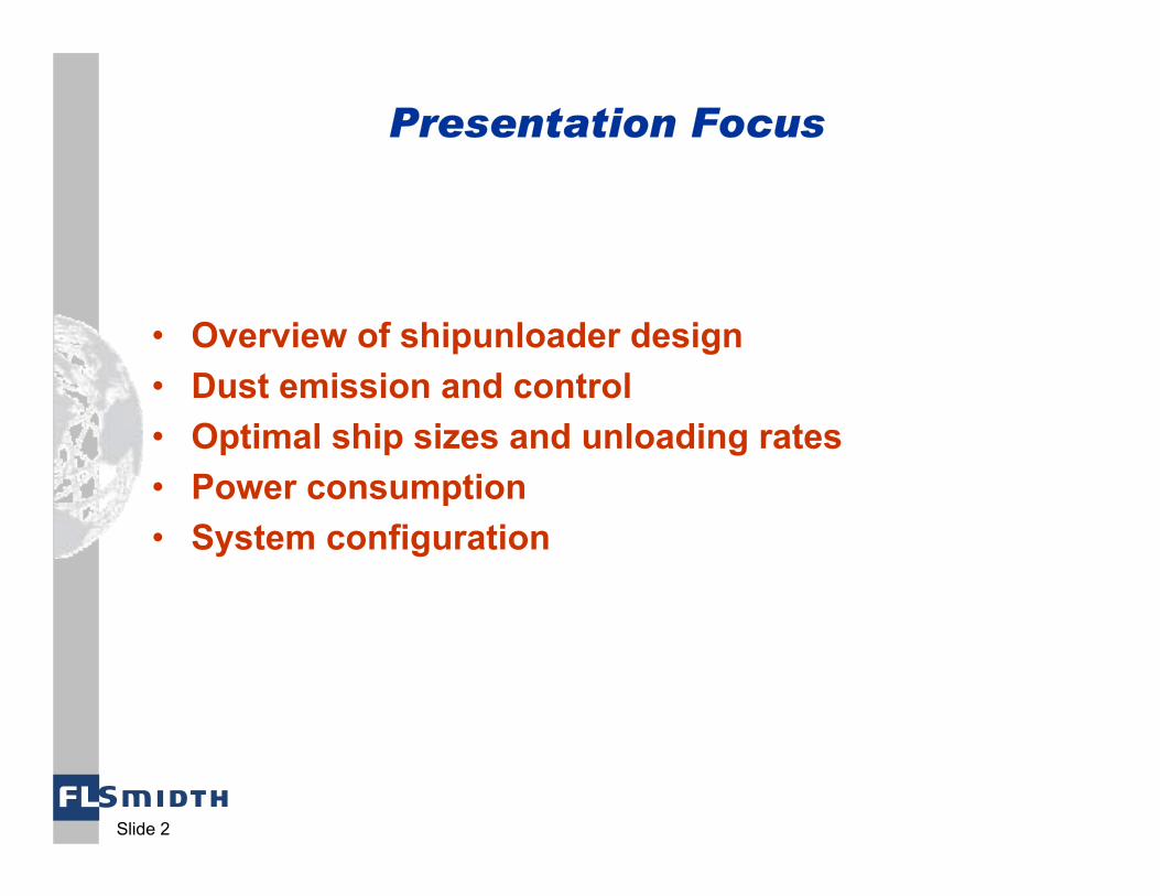
PneumaticMechanical
PNEUMATIC VS MECHANICAL POWER CONSUMPTION (BASED ON 1000’ CONVEY DISTANCE)
DESIGN CAPACITY (MTPH)
AP
PR
OX
IMA
TE
CO
NS
UM
ED
PO
WE
R (
kW)

Slide 13
Materials
ALUMINABARLEYCASSAVACEMENTCOALCITRUS PULPCLINKERDERIVATIVESFERTILIZERFISH MEALFLOURGYPSUMGRAIN
KAOLINLIMESTONEMANIOCPHOSPHATE ROCKRAPE SEEDRICESOY BEANSSOY MEALSOY PELLETSSALTSULPHURTAPIOCA MEALTAPIOCA PELLETS
MECHANICAL
ALUMINACEMENTFLY ASHGRAINPET COKE
PNEUMATIC

Slide 14
System Configuration
• Optimal efficiency for mechanical shipunloaders is reliant on limitless movement along the vessel, therefore stationary unloaders are not practical for large vessel, high-capacity applications
• Fixed vertical arm length and limited up/down movement of the horizontal arm can make the application impractical where there are high water level fluctuations
Mechanical Shipunloaders

Slide 15
System Configuration
• Fixed position of shore transfer system makes barge mounting impractical

Slide 16
System Configuration
• Greater range of arm movement allows for more coverage from a fixed position. Also, flexible hoses allow for limited movement between connections (typically 50’ +/-)
•Three-section arm better compensates for variable water level conditions
Pneumatic Shipunloaders
Slide 17
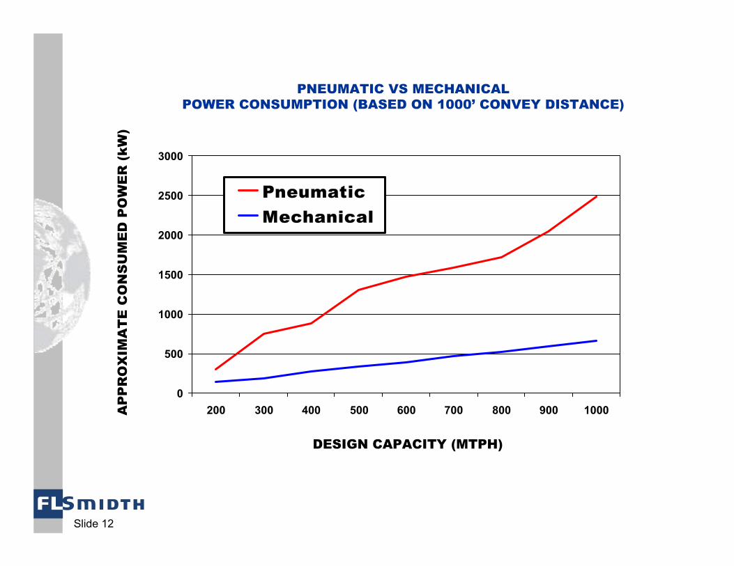
System Configuration
• Use of flexible hoses make barge mounting a practical option for pneumatic shipunloaders

Slide 18
System Configuration
Note: Pneumatic transfer (with flexible hose connection) is an option for mechanical unloaders, however power savings are often negated

Slide 19
System Summary
+Configuration Versatility
+Coarse, Abrasive Materials
++Powdery (cementitious) Materials
LowestHighestPower Consumption
+ *+Dust Control
+Design Capacity > 800 MTPH
++Design Capacity 700 MTPH to 800 MTPH
+Design Capacity up to 700 MTPH
+Panamax Vessels ( > 55,000 DWT)
++Handimax Vessels (40,000 to 55,000 DWT)
+Small Vessels (< 40,000 DWT)
MECHANICALPNEUMATIC
* Dependent on shore transfer system

Slide 20
FLSMIDTHYour single source for
pneumatic and mechanical shipunloaders!