Embed Size (px)
Citation preview
1
Measuring Atmospheric Optical
Depth Directly from Satellite
Imagery
Stephen Schiller
Raytheon Space and Airborne Systems
Phone: 310-615-7951
E-mail: [email protected]
Copyright © 2011 Raytheon Company All Rights Reserved

Page 2Space and Airborne Systems
Presentation Outline
The SPARC method and radiative transfer equation.
The SPARC solar radiometry mode.
Deriving the “zero atmosphere response constant”
for the direct solar radiometric calibration of the
IKONOS commercial sensor.
Measuring atmospheric transmittance from image
data alone
Validation of IKONOS/SPARC vertical optical depth
measurements relative to ground truth solar
radiometry
Copyright © 2011 Raytheon Company All Rights Reserved
Page 3Space and Airborne Systems
The SPecular Array Radiometric Calibration (SPARC) Method
3
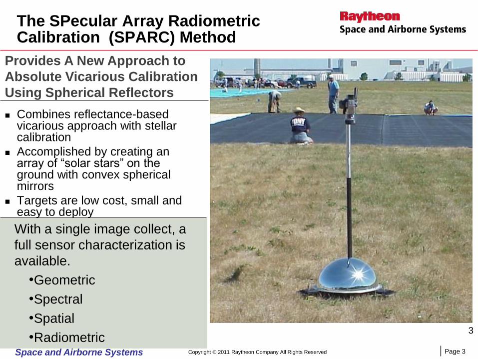
Combines reflectance-based vicarious approach with stellar calibration
Accomplished by creating an array of “solar stars” on the ground with convex spherical mirrors
Targets are low cost, small and easy to deploy
Provides A New Approach to
Absolute Vicarious Calibration
Using Spherical Reflectors
With a single image collect, a
full sensor characterization is
available.
•Geometric
•Spectral
•Spatial
•RadiometricCopyright © 2011 Raytheon Company All Rights Reserved
Page 4Space and Airborne Systems
4
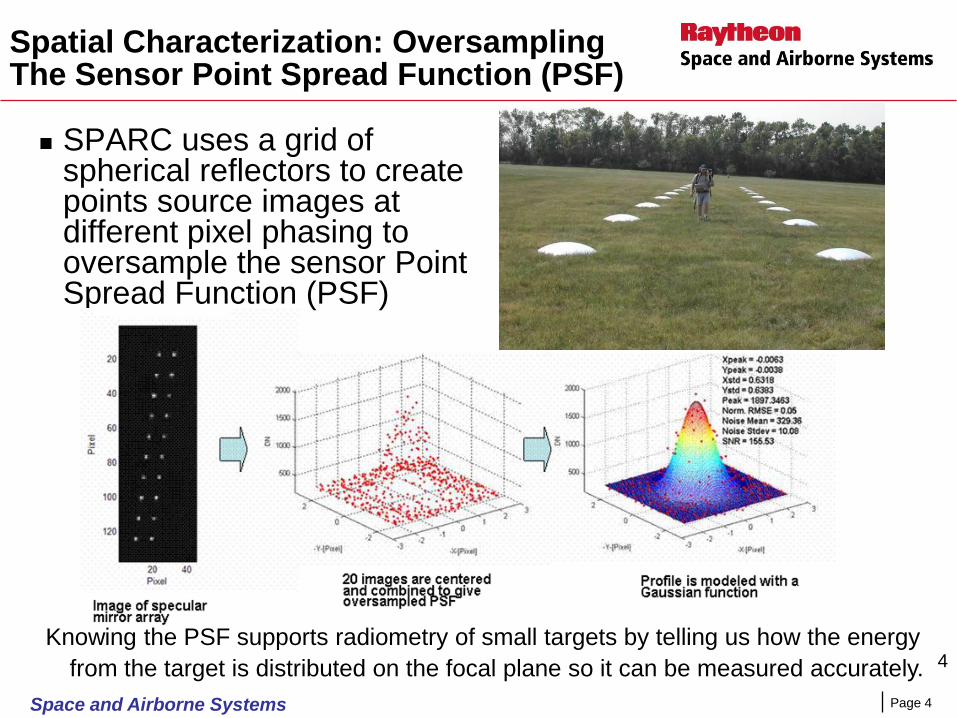
Spatial Characterization: Oversampling The Sensor Point Spread Function (PSF)
SPARC uses a grid of spherical reflectors to create points source images at different pixel phasing to oversample the sensor Point Spread Function (PSF)
Knowing the PSF supports radiometry of small targets by telling us how the energy
from the target is distributed on the focal plane so it can be measured accurately.

Page 5Space and Airborne Systems
SPARC uses panels of convex spherical mirrors to create a set of radiometric targets with a known at-sensor radiance.
Individual mirrors produce a virtual image of the sun with an upwelling intensity determined by the mirrors radius of curvature.
Total intensity of each target is quantized by the number of mirrors.
SPARC design results in a simplified radiative transfer equation for calculating accurate values of at-sensor radiance.
Only ground truth data required in the field for the calculation of at-sensor radiance is atmospheric transmittance.
Provides calculation of sensor calibration coefficients for conversion of pixel digital number (DN) to absolute radiance [Watts/(m2 ster µm)]
Radiometric Characterization and Calibration
SPARC Target At-Sensor Radiance Spectrum
Maginitude Quantized by the Number of Mirrors
0
0.2
0.4
0.6
0.8
1
1.2
0.4
0.4
4
0.4
7
0.5
1
0.5
4
0.5
8
0.6
2
0.6
5
0.6
9
0.7
2
0.7
6
0.8
0.8
3
0.8
7
0.9
0.9
4
0.9
8
1.0
1
1.0
5
1.0
8
Wavelength (Microns)
Rad
ian
ce (
W/c
m2 s
ter
mic
ron
)
1M
5M
10M
20M
30M
40M
50M
60M
70M
Copyright © 2011 Raytheon Company All Rights Reserved
Page 6Space and Airborne Systems
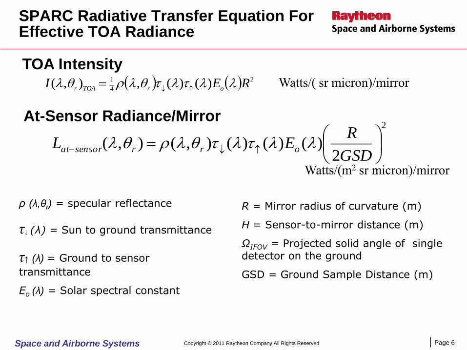
SPARC Radiative Transfer Equation For Effective TOA Radiance
2
2)()()(),(),(
GSD
REL orrsensorat
)()(,),( 2
4
1 REIorTOAr
At-Sensor Radiance/Mirror
Watts/(m2 sr micron)/mirror
TOA IntensityWatts/( sr micron)/mirror
R = Mirror radius of curvature (m)
H = Sensor-to-mirror distance (m)
ΩIFOV = Projected solid angle of single detector on the ground
GSD = Ground Sample Distance (m)
ρ (λ,θr) = specular reflectance
τ↓ (λ) = Sun to ground transmittance
τ↑ (λ) = Ground to sensor
transmittance
Eo (λ) = Solar spectral constant
Copyright © 2011 Raytheon Company All Rights Reserved
Page 7Space and Airborne Systems
7
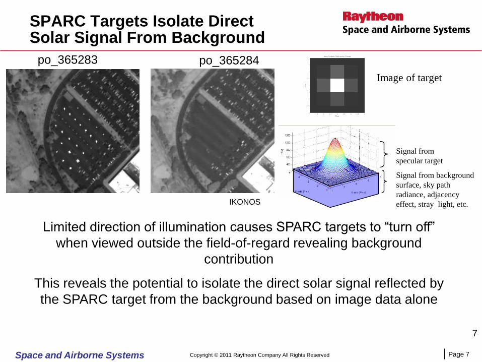
SPARC Targets Isolate Direct Solar Signal From Background
po_365283 po_365284
Limited direction of illumination causes SPARC targets to “turn off”
when viewed outside the field-of-regard revealing background
contribution
This reveals the potential to isolate the direct solar signal reflected by
the SPARC target from the background based on image data alone
IKONOS
Image of target
Signal from background
surface, sky path
radiance, adjacency
effect, stray light, etc.
Signal from
specular target
Copyright © 2011 Raytheon Company All Rights Reserved

Page 8Space and Airborne Systems
Transmittance Is The Only Atmospheric Component Affecting The Sensor Response To The Reflected Direct Solar Signal
Outcome is the potential for the satellite to emulate a sun
photometer/radiometer using SPARC reflectors
ρ– Specular Reflectance
Eo – Top-of-atmosphere
solar spectral irradiance
τ↓ – Sun to target
transmittance
τ↑– Target to sensor
transmittance
RayleighOHaerooz 2
Zenith
θsen θsun
Total Transmittance
For spectral bands in which the extinction
law applies
sune sec
sene
sec
or
)sec(sec sensune
Vertical Optical Depth in a uniform
atmosphere
Copyright © 2011 Raytheon Company All Rights Reserved
Page 9Space and Airborne Systems
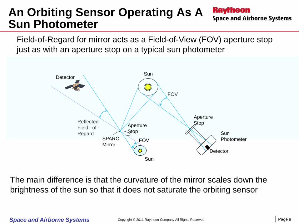
An Orbiting Sensor Operating As A Sun Photometer
Field-of-Regard for mirror acts as a Field-of-View (FOV) aperture stop
just as with an aperture stop on a typical sun photometer
FOV
FOV
Reflected
Field –of -
Regard
Detector
Detector
Aperture
Stop
Aperture
Stop
SPARC
Mirror
Sun
Photometer
Sun
Sun
The main difference is that the curvature of the mirror scales down the
brightness of the sun so that it does not saturate the orbiting sensor
Copyright © 2011 Raytheon Company All Rights Reserved

Page 10Space and Airborne Systems
Potential Advantages Of Sensor Based Sun Photometry
Placing a SPARC panel of reflectors somewhere in an image– Creates the potential to measure the transmittance through the total
atmospheric path length affecting the image data (the transmittance from the
ground to the sensor cannot be measured directly any other way).
– Allows transmittance to be measured simultaneously with the signal from all the
targets in the image. (provides accurate scene-based atmospheric corrections)
– Creates the potential to know the total transmittance even in poor and non-
uniform optical depth sky conditions. (Can make measurements of ground
reflectance more productive in usually marginal weather conditions)
– Allows transmittance to be measured in the actual Relative Spectral Response
(RSR) of a sensor spectral band. (No RSR conversion error)
Once the imaging sensor is calibrated, a simple mirror panel allows the sensor
itself to perform the function of an in situ solar radiometer
Copyright © 2011 Raytheon Company All Rights Reserved
Page 11Space and Airborne Systems
Calibrating The Imaging Sensor For Sun Photometry
With a sun photometer, calibration requires determining the
top-of-atmosphere response (Io) representing the solar
spectral constant in the instruments radiometric scale .
– This is usually digital numbers representing the detector output in Volts
With SPARC sun photometry, the equivalent calibration
requires determining the “Zero Atmosphere Response
Constant”.
– This is the orbiting sensor digital number (DN) response to a solar
illuminated SPARC reflector when the atmospheric transmittance = 1.
– The response is the integrated (∑DN) over the image PSF of a SPARC
reflector panel containing N identical mirrors.
Copyright © 2011 Raytheon Company All Rights Reserved
Page 12Space and Airborne Systems
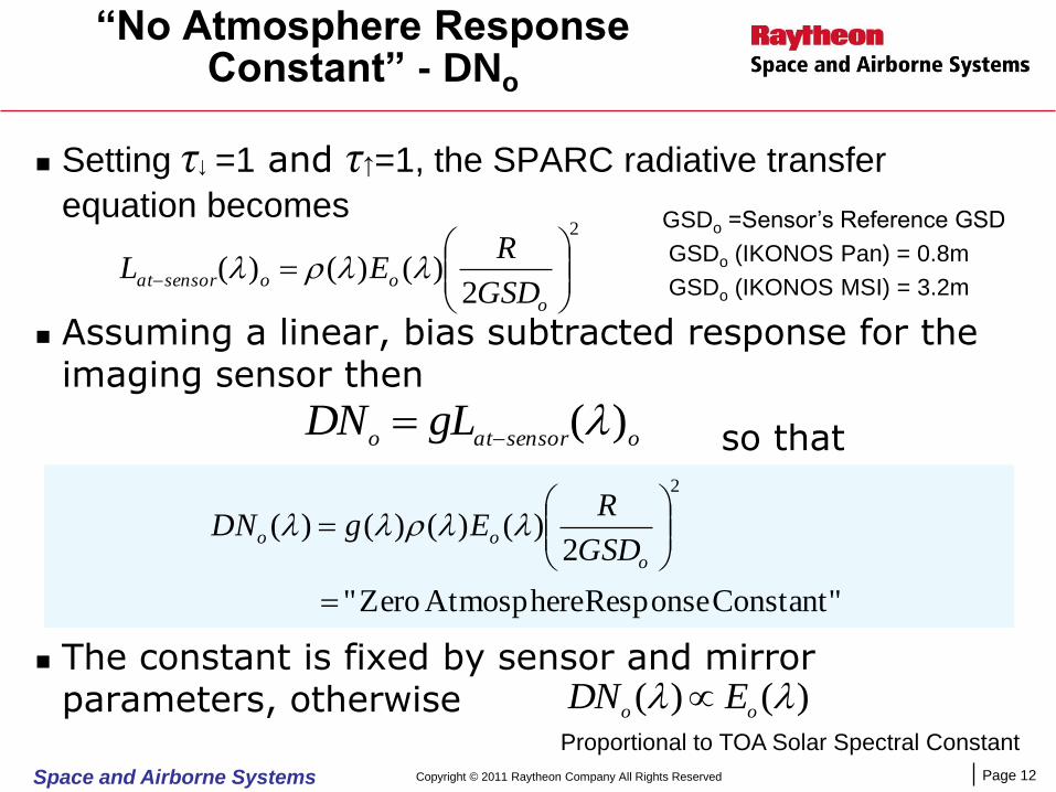
“No Atmosphere Response Constant” - DNo
Setting τ↓ =1 and τ↑=1, the SPARC radiative transfer
equation becomes
Assuming a linear, bias subtracted response for the imaging sensor then
so that
The constant is fixed by sensor and mirror parameters, otherwise
2
2)()()(
o
oosensoratGSD
REL
osensoratogLDN )(
GSDo =Sensor’s Reference GSD
GSDo (IKONOS Pan) = 0.8m
GSDo (IKONOS MSI) = 3.2m
Constant" Response Atmosphere Zero"
2)()()()(
2
o
ooGSD
REgDN
)()( oo
EDN Proportional to TOA Solar Spectral Constant
Copyright © 2011 Raytheon Company All Rights Reserved

Page 13Space and Airborne Systems
SPARC Measured Atmospheric Transmittance
In any atmosphere, when imaging a SPARC reflector, the
DN/mirror response will be
Solving for Total Transmittance
Once the “Zero Atmosphere” digital number (DNo) response
is determined for a imaging sensor, atmospheric
transmittance in any spectral band can be measured from
image data alone.
2
2
1
2)()()()()()()()(
GSD
REgLgDN
osensorat
= DN0GSDo2 (insert)
)(
)()()()(
2
2
ooDNGSD
DNGSD
Copyright © 2011 Raytheon Company All Rights Reserved

Page 14Space and Airborne Systems
Measuring DNo -Part 1
Task sensor under calibration to image SPARC Panels in uniform
sky conditions
Operate a ground based sun photometer to measure aerosol
optical depth, ozone and water vapor columnar amounts during
collects
Build a MODTRAN model to reproduce and spectra for
the solar illumination and sensor view geometry of the image.
Integrate MODTRAN transmittance spectra with sensor RSR to
get and in each sensor band. Band transmittance
=∑(Trans(λ)*RSR(λ))/∑ RSR(λ)
)(
)(
)(
)(
0.4 0.5 0.6 0.7 0.8 0.9 1 1.10
0.1
0.2
0.3
0.4
0.5
0.6
0.7
0.8
0.9
1
Wavelength (m)
Rela
tive
Sp
ectr
al
Re
spo
nse
Pan
Blue
Green
Red
NIR
IKONOS RSR Curves
Wavelength (nm)
Tra
nsm
itta
nc
e
400 600 800 1000 1200
0.3
0.4
0.5
0.6
0.7
0.8
0.9
MODTRAN Model Fit To Observed TransmittanceJuly 23, 2009 IKONOS Overpass, 18:54 UTC
MFRSR Obs.Vis = 39 km
1976 Std Atmos. + User Defined Aerosols From Measured Angstrom Coefficients
IKONOS
band
integrated
Pan and MSI
transmittance
values
Blue
Green
RedPan
NIR
Copyright © 2011 Raytheon Company All Rights Reserved
Page 15Space and Airborne Systems
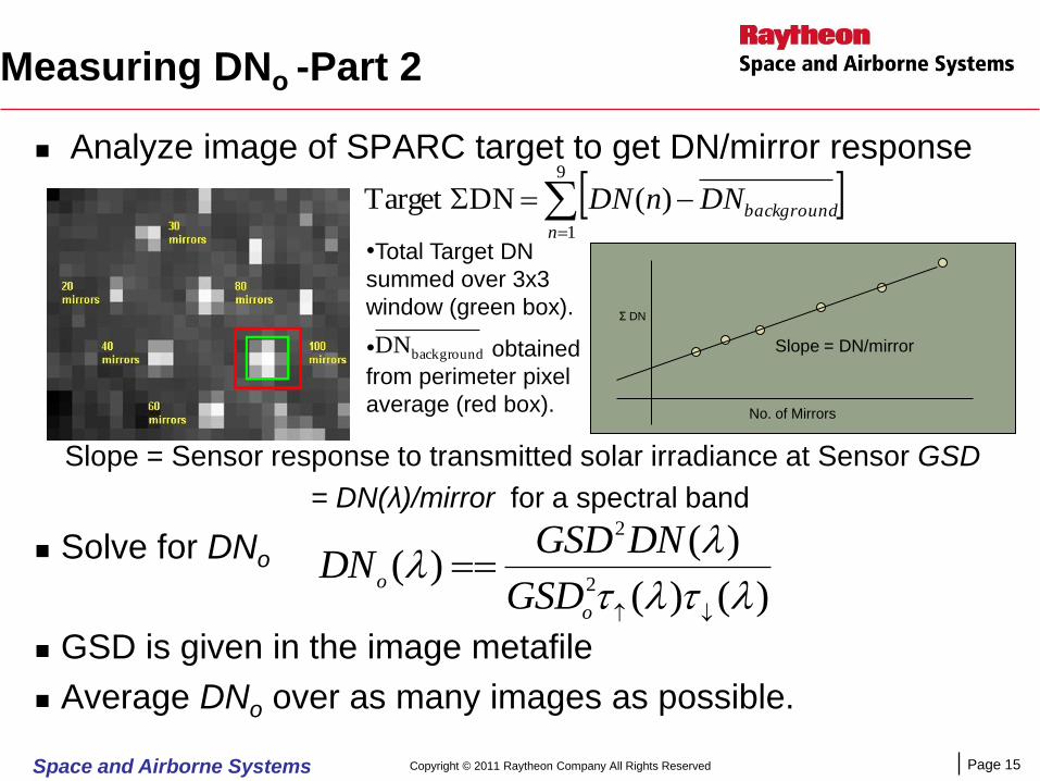
Measuring DNo -Part 2
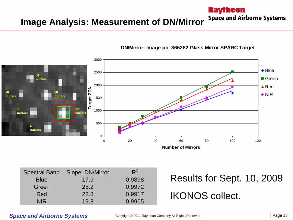
Analyze image of SPARC target to get DN/mirror response
Solve for DNo
GSD is given in the image metafile
Average DNo over as many images as possible.
9
1
)(DNTarget n
backgroundDNnDN
•Total Target DN
summed over 3x3
window (green box).
• obtained
from perimeter pixel
average (red box).
backgroundDN
Slope = Sensor response to transmitted solar irradiance at Sensor GSD
= DN(λ)/mirror for a spectral band
)()(
)()(
2
2
o
oGSD
DNGSDDN
Σ DN
No. of Mirrors
Slope = DN/mirror
Copyright © 2011 Raytheon Company All Rights Reserved

Page 16Space and Airborne Systems
Validation: Sun Photometry Obtained With IKONOS (2009)
July 23 July 31 Sept 2
Sept 10 Nov 15
•Five overpass days
•Two collects per
overpass
•10 calibration points for
determining an average
DNo.
Page 17Space and Airborne Systems
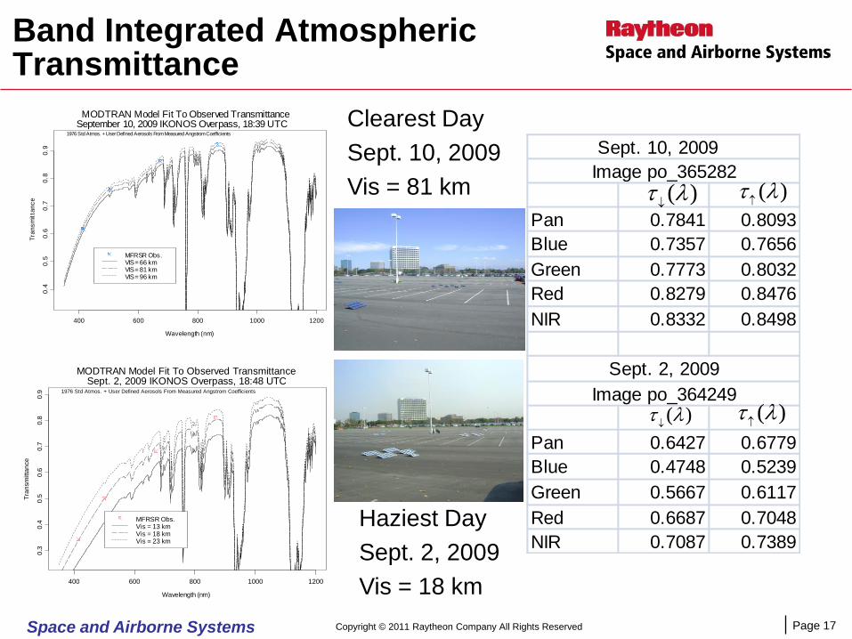
Band Integrated Atmospheric Transmittance
Wavelength (nm)
Tra
nsm
itta
nce
400 600 800 1000 1200
0.3
0.4
0.5
0.6
0.7
0.8
0.9
MODTRAN Model Fit To Observed TransmittanceSept. 2, 2009 IKONOS Overpass, 18:48 UTC
MFRSR Obs.Vis = 13 kmVis = 18 kmVis = 23 km
1976 Std Atmos. + User Defined Aerosols From Measured Angstrom Coefficients
Wavelength (nm)
Tra
nsm
itta
nc
e
400 600 800 1000 1200
0.4
0.5
0.6
0.7
0.8
0.9
MODTRAN Model Fit To Observed TransmittanceSeptember 10, 2009 IKONOS Overpass, 18:39 UTC
MFRSR Obs.VIS = 66 kmVIS = 81 kmVIS = 96 km
1976 Std Atmos. + User Defined Aerosols From Measured Angstrom Coefficients
Clearest Day
Sept. 10, 2009
Vis = 81 km
Haziest Day
Sept. 2, 2009
Vis = 18 km
Pan 0.7841 0.8093
Blue 0.7357 0.7656
Green 0.7773 0.8032
Red 0.8279 0.8476
NIR 0.8332 0.8498
Pan 0.6427 0.6779
Blue 0.4748 0.5239
Green 0.5667 0.6117
Red 0.6687 0.7048
NIR 0.7087 0.7389
Sept. 10, 2009
Image po_365282
Sept. 2, 2009
Image po_364249
)()(
)(
)(
Copyright © 2011 Raytheon Company All Rights Reserved
Page 18Space and Airborne Systems
Image Analysis: Measurement of DN/Mirror
Results for Sept. 10, 2009
IKONOS collect.
DN/Mirror: Image po_365282 Glass Mirror SPARC Target
0
500
1000
1500
2000
2500
3000
0 20 40 60 80 100 120
Number of Mirrors
Targ
et
ΣD
N
Blue
Green
Red
NIR
Spectral Band Slope: DN/Mirror R2
Blue 17.9 0.9898
Green 25.2 0.9972
Red 22.8 0.9917
NIR 19.8 0.9965
Copyright © 2011 Raytheon Company All Rights Reserved
Page 19Space and Airborne Systems
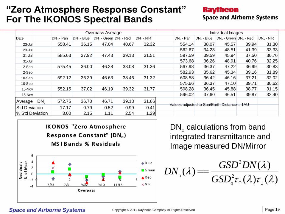
Date DNo - Pan DNo - Blue DNo - Green DNo - Red DNo - NIR DNo - Pan DNo - Blue DNo - Green DNo - Red DNo - NIR
23-Jul 558.41 36.15 47.04 40.67 32.32 554.14 38.07 45.57 39.94 31.30
23-Jul 562.67 34.23 48.51 41.39 33.33
31-Jul 585.63 37.92 47.43 39.13 31.51 597.59 39.59 45.94 37.50 30.76
31-Jul 573.68 36.26 48.91 40.76 32.25
2-Sep 575.45 36.00 46.28 38.08 31.36 567.98 36.37 47.22 36.99 30.83
2-Sep 582.93 35.62 45.34 39.16 31.89
10-Sep 592.12 36.39 46.63 38.46 31.32 608.58 36.42 46.16 37.21 32.02
10-Sep 575.66 36.37 47.10 39.71 30.62
15-Nov 552.15 37.02 46.19 39.32 31.77 508.28 36.45 45.88 38.77 31.15
15-Nov 596.02 37.60 46.51 39.87 32.40
Average DNo 572.75 36.70 46.71 39.13 31.66
Std Deviation 17.17 0.79 0.52 0.99 0.41
% Std Deviation 3.00 2.15 1.11 2.54 1.29
Overpass Average Individual Images
“Zero Atmosphere Response Constant” For The IKONOS Spectral Bands
Values adjusted to Sun/Earth Distance = 1AU
DNo calculations from band
integrated transmittance and
Image measured DN/Mirror
)()(
)()(
2
2
o
oGSD
DNGSDDN
Copyright © 2011 Raytheon Company All Rights Reserved
IK ONOS "Zero Atmos phere
R es pons e C ons tant" (DNo)
MS I B ands % R es iduals
-4
-2
0
2
4
6
0 1 2 3 4 5 6
Overpa ss
Re
sid
ua
ls
% o
f M
ea
n B lue
G reen
R ed
NIR7/23 9/027/31 9/10 11/15

Page 20Space and Airborne Systems
Atmospheric Transmittance Results
0.20
0.30
0.40
0.50
0.60
0.70
0.80
0 2 4 6 8 10
Tran
smit
tan
ce
Image Number
Comparison Of Sun Photometer and IKONOS Measurements For Total Path Atmospheric Transmittance
Blue - Sun Photometer
Blue - IKONOS DNo
Green - Sun Photometer
Green - IKONOS DNo
Red - Sun Photometer
Red - IKONOS DNo
NIR - Sun Photometer
NIR - IKONOS DNo
Date Pan Blue Green Red NIR Pan Blue Green Red NIR
1 23-Jul 0.570 0.468 0.536 0.623 0.642 0.535 0.478 0.515 0.626 0.625
2 23-Jul 0.573 0.471 0.539 0.625 0.644 0.546 0.432 0.551 0.651 0.668
3 31-Jul 0.529 0.396 0.476 0.575 0.606 0.536 0.421 0.461 0.543 0.580
4 31-Jul 0.528 0.395 0.475 0.574 0.605 0.513 0.384 0.490 0.589 0.607
5 2-Sep 0.436 0.249 0.347 0.471 0.524 0.422 0.244 0.347 0.442 0.506
6 2-Sep 0.436 0.249 0.347 0.472 0.524 0.433 0.240 0.333 0.468 0.523
7 10-Sep 0.635 0.563 0.624 0.702 0.708 0.660 0.555 0.613 0.663 0.711
8 10-Sep 0.632 0.560 0.622 0.700 0.706 0.622 0.552 0.623 0.705 0.679
9 15-Nov 0.641 0.506 0.586 0.686 0.714 0.566 0.508 0.582 0.687 0.710
10 15-Nov 0.638 0.501 0.582 0.683 0.711 0.661 0.519 0.585 0.703 0.736
IKONOS Measured Transmittance Based on Mean DNoSun Photometer Measured Transmittance
Based on the SPARC
radiative transfer model,
method and targets, results
show IKONOS is able to
measure atmospheric
transmittance over a wide
range of atmospheric
conditions within a few
percent of the ground based
sun photometer.
Copyright © 2011 Raytheon Company All Rights Reserved

Page 21Space and Airborne Systems
Optical Depth Retrieval For Each Overpass
•Assuming a uniform plane parallel atmosphere, The
transmittance can be converted to an optical depth.
•The average residual between the ground based sun photometer
measurement and the IKONOS/SPARC measurement is ≤0.01 for
each band
)sec(sec
ln
sensun
C omparis on Of S un P hotometer And IK ONOS /S P AR C Meas urements Of
Atmos pheric Vertic al Optic al Depth
0.000
0.100
0.200
0.300
0.400
0.500
0.600
0.700
0 1 2 3 4 5 6
Overpa ss
Ve
rtic
al
Op
tic
al
De
pth B lue - S un P hotometer
B lue - IK ONOS /S P AR C
G reen - S un P hotometer
G reen -IK ONOS /S P AR CR ed - S un P hotometer
R ed - IK ONOS /S P AR C
NIR - S un P hotometer
NIR - IK ONOS /S P AR C
Residuals
Pan Blue Green Red NIR
23-Jul 0.020 0.015 0.004 0.011 0.002
31-Jul 0.003 0.008 0.000 0.008 0.010
2-Sep 0.002 0.013 0.008 0.017 0.008
10-Sep 0.012 0.007 0.004 0.011 0.008
15-Nov 0.011 0.007 0.000 0.006 0.005
Mean 0.009 0.010 0.003 0.010 0.007
Copyright © 2011 Raytheon Company All Rights Reserved
Noise reduction by averaging measurements
from 2 images per overpass Performance of ground based sun photometer is
accurately transferred to IKONOS

Page 22Space and Airborne Systems
Conclusion
SPARC targets provide a practical approach for measuring atmospheric
transmittance directly from image data alone recorded by an over flying
sensor.
Once the sensor is calibrated for a panel of mirrors (based on ground truth
sun photometry), transmittance can be measured at any location by simply
placing a panel with equivalent mirrors in the scene.
Transmittance measurements are for the full sun-to-ground-to-sensor
atmospheric path length and are recorded in the actual pass band of the
sensor.
Sensor calibration, in the instrumental radiometric scale, was achieved at ≤
2.5% 1σ repeatability for the IKONOS MSI bands (5 overpasses, 5 months).
Results demonstrated average residuals ≤0.01 in measurements of vertical
optical depth from image data alone compared to the coincident sun
photometer measurements used for calibration.
Acknowledgement: We want to thank Martin Taylor and GeoEye for their
collaboration in providing the IKONOS data used in this research.
Copyright © 2011 Raytheon Company All Rights Reserved