Embed Size (px)
Citation preview

Measuring AmplifierSystem
MGCplus
Specifications
B0554-17.0 en


System devices*)
Mains supply
Supply voltage
Max. input nominal (rated) current
Start-up current
V AC
A
A
115 V/230 V −25+15 %
2.2/1.3
<20
Battery supply
Battery voltage
Max. input nominal current
Start-up current
V DC
A
A
12 V/24 V −25+15 %
13.4/6.7
<20
Max. power consumption W 150
Nominal (rated) temperature range °C [°F] 1...16 slots, desktop housing−10 ... +55 [+14 ... +131]
19” rack frame−10 ... +55 [+14 ... +131]
Type of protection desktop housing IP20 19” rack frame IP20
Dimensions desktop housing (w x h x d in mm) (1 mm = 0.03937 inches)
Desktop housing Rack frame Max. number of slots Supply voltage(V)
Weight, approx. (kg)TG/ER
TG001D − 6 230 V (115) 6
TG010D − 6 (with AB32) 230 V (115) 8
TG002D − 6 12/24 = 6
TG003D ER003D 16 230 V (115) 7/6
TG004D ER004D 16 12/24 = 7.5/6
TG009D − 2 230 V (115) 5
*) The MGCplus system is tested according to the harmonized European standards EN61326 and EN61010 Therefore it achieves the protectionaims of EEC directive 89/336EEC in the field of electromagnetic compatibility and EEC directive 73/23/EEC in the field of electrical safety oflow voltage equipment. Mechanical stress is tested according to European Standard EN60068−2−6 for vibrations and EN60068−2−27 forshock. The equipment is exposed to an acceleration of 25 m/s2 within the frequency range of 5...65 Hz in all 3 axes. Duration of this vibrationtest: 30 min per axis. The shock test is performed with a rated value of 200 m/s2 acceleration during 11 ms, half sine pulse shape, with 3shocks in each of the 6 possible directions.
19” rack module ER003D/004D (482x133x375)
Desktop housing TG009D (173x171x367) Desktop housing TG001D/002D (255x171x367)
Desktop housing TG010D/003D/004D (458x171x367)
B0554-17.0 en HBM3

System devices MGCsplit1−NT650/1−NT651 power packs
Input voltage range, nominal V DCV DC
10 … 5012, 24 and 42 (suitable for all common automotive vehicle electrical systems)
Output voltage V DC 28 2%
Max. continuous output current A 3,5
Max. number of connectableMGCsplit modules
−10 (e.g. 1x SH400CP, 9x SH400 or SH650;one module less, if an ABX22 is connected)
Ride−through start−upIntrusion at > 8.5V
NT650 only:Intrusion at < 8.5V
−
s
(ride−through times without measurement system failure)unlimited
min. 10
Voltage discontinuityNT650:
NT651:
ss
msms
(typical ride−through times without measurement system failure)10 at full load (100 W)60 at a load of 1x SH400CP42+ 2x SH65015 at full load (100 W)50 at a load of 1x SH400CP42+ 2x SH650
Start from standby mode − Via CAN message and digital control signal
Power consumption at standby mode W <1.2
CAN hardware bus link
Baud rate
−
kBits/s
Standard CAN as per ISO11898
250
Electrical isolation of digital input V DC 500, typically
Input voltage range of digital inputV DC 0 … 50
Input current of digital input mA < 3
Low level of digital input V < 1
High level of digital input V > 3
Protection against false operation − Sustained short−circuit proof, polarity reversal protection,cutoff at excess temperature
Degree of protection − IP65
Operating temperature range °C −30 … +70
Nominal temperature range °C −20 … +60
Permissible relative humidity % 100
Connections − Power supplySplit line IN / OUTCAN / digital input
Connection techniquePower supply
Split line IN / OUT
CAN / digital input
− ODU Minisnap, series B, design S3, size 24−pin, 60° coding (suitable connector for cable mounting
e.g. S32BFC−T04LPH0−6000)16−pin, no coding (suitable connector for cable mounting
e.g. S32B0C−T16PFG0−7500)6−pin, 30° coding (suitable connector for cable mounting
e.g. S32BAC−T06MPH0−6000)
WeightNT650NT651
kgkg
3.152.70
Dimensions (W x H x D) mm 104 x 146 x 205
B0554-17.0 enHBM 4

Modules *) 1−SH400 1−SH650 1−SH400CP
Function Enclosure for one MLxx amplifier and max. two connectionboards (each 4 divs wide)
Enclosure for thecommunication processor
Degree of protection IP40 IP65 IP40
Operating temperature range °C [°F] −30 ... +70 [−22 ... +158] −30 ... +70 [−22 ... +158] −20 ... +60 [−4 ... +140]
Nominal (rated) temperaturerange
°C [°F] −20 ... +60 [−4 ... +140]
Permissible relative humidity % 95 at 40 °C [104 °F] 100 95 at 40 °C [104 °F]
Supply voltage V 18 ...32
Connections − S Split−Line Input/Output
S As on the resp. connectionboards
S Split−Line Input/Output
S ODU connectors (Lemo
compatible)
S Connection for ABX22A
S With CP22 and CP42:
100 Mbit-Ethernet; USB;RS-232-C
Weight without amplifier andconnection board, approx. kg 1.6
Dimensions (W x H x D) mm 104 x 146 x 205
*) See MGCplus system specifications for measurement properties of amplifier modules.
Split-Line
Total length m 25 (from 1−SH400CP through last module)
Max. number of measurementmodules
− 16
Baud rate Meas./s 307,200; 4−byte format (like MGCplus)
Bus termination − Connected automatically
B0554-17.0 en HBM5

Enclosure dimensions MGCsplit (in mm; 1 mm = 0.03937 inches)
Mounting dimensions MGCsplit (in mm; 1 mm = 0.03937 inches)
Rear mounting Lateral mounting
B0554-17.0 enHBM 6

General technical data single-channel amplifier modulesWidth mm 20.3 (4 divs)1)
Maximum sampling rate without linearisation values/s 19200
Limit value switchesNumberReference levelReference voltage (freely adjustable)Hysteresis factory settingAdjustment accuracy
%%%
4
Gross, net, peak values−100 ...+100 of measuring range
1 of measuring range0.0033 of measuring range
Response time ms 1.0with Butterworth filter > 5 Hzand Bessel filter > 1.25 Hz
Peak value storeNumberFunctionPeak combine
2
Maximum, minimumPeak-peak, average
Update time µs 30 with Butterworth filter > 250 Hz
and Bessel filter > 100 HzClearing the peak value stores (switching to current value) within 1 ms, via control inputsHolding of the current value/peak value within 1 ms, via control inputsTime constant for envelope curve function s 0.01 ... 10000
Control contacts (HCMOS)Inputs (8 lines, connectable as desired)
Permissible input voltageHigh levelLow levelSchmitt-trigger, hysteresisPull-up resistors
VVVV
kΩ
−0.5 to +5.5min. +4.0max. +0.7
> 1.1100
Outputs (limit value switch, error)High level with max. 1 mALow level with max. 0.7 mAInternal resistance
VV
kΩ
> 4.0< 0.7
1
Nominal (rated) temperature range Service temperature range Storage temperature range
°C [°F]°C [°F]°C [°F]
−20 ...+60 [−4 ... +140] −20 ...+60 [−4 ... +140] −25 ...+70 [−13 ... +158]
Operating voltages V 14.6...17.0; (< 120 mA) 7.7...8.3; (< 120 mA)2)
+4.9...5.1; (< 150 mA)Card format (Euro)Weight
mmg
100 x 160300
Connection plug IEC 603-2 indirectly
Analog outputs Vo1 and Vo2Nominal (rated) voltagePermissible load resistanceInternal resistanceThe two output voltages can be used to display the five signal voltages.
V
kΩΩ
10 V (asymmetrical)
> 5< 5
Amplifier output with zero balanceOutput staggered by the tare value
Peak value store 1 output (maximum or minimum)Peak value store 2 output (maximum or minimum)
Peak value store 3 output (peak combine of 1 and 2)
Max. deviation of the analog outputs from thedigital value mV < 3 (< 10 with ML10B)
Monitor output for Vo1 via BNC plug on front panelNominal (rated) voltage Permissible load resistanceInternal resistance
VkΩkΩ
10 (asymmetrical)> 1000
1Effect of a 10K-change of the ambient temperature(effect additional to digital value)on the outputs Vo1 and Vo2:
sensitivityzero point
%mV
< 0.08, typ. 0.04< 3 typ. 2
1) With ML38B: 40.6 mm (8 divs)2) Also connectable to 16 V
B0554-17.0 en HBM7

ML01B single-channel amplifier modulesAccuracy class 0.03
DC amplifierInput for voltage measurement symmetrical
Input signal range (selectable)Measuring range (digitally adjustable) Zero offset Measuring frequency range
VVV
Hz
−10.2 ...+10.2 −0.0765 ...+0.07650.4 ... 10.2 0.002 ... 0.076510 0.0750 ... 2400 -1 dB1) 0 ... 250 −1 dB
Internal resistance of the signal voltage source kΩ < 1.3Input for thermocouple measurement
Measuring range (digitally adjustable)Linearisation error (with AP09 connection board)
Linearisation rangeNiCr-Ni (K)Fe-CuNi (J)Cu-CuNi (T)NiCr-CuNi (E)NiCrSi-NiSi (N)Pt10Rh-Pt (S)Pt30Rh-Pt6Rh (B)Pt13Rh−Pt(R)
°C, [°F]°C°C
°C°C°C°C°C°C°C°C
10 ... 3275, [50 ... 5927]< 0.06 < 0.25 (K, J, T, E, N)
< 0.6 (S, B, R)
−158 ... +1414 −191 ... +1414−167 ... +1192 −190 ... +1192−210 ... +393 −237 ... +393−161 ... +1005 −205 ... +1005−186 ... +1300 −219 ... +1300+181 ... +1755 −50 ... +1755+570 ... +1814 +160 ... +1814+178 ... +1769 −50 ... +1769
Max. internal resistance kΩ 1.3Temperature range for cold junction 2) °C, [°F] −20 ...+ 60, [−4 ...+140]
Max. permissible common-mode voltage V 62Input for current measurement asymmetrical (to an internal 50 Ω standard resistor)
Input signal rangeMeasuring range (digitally adjustable) Max. measuring frequency rangeZero offset, adjustable (”living” zero point)
mAmAHzmA
−50 ...+504 ... 50
0 ... 2400 -1 dB 0 ...50
Measuring frequency rangeButterworth low pass
Nom.val. fc −1dB −3dB Phase del. Rise time Over- (Hz) (Hz) (Hz) (ms) (ms) shoot %
2400 3) 2400 3250 0.28 0.105 5.22000 3) 2050 2350 0.40 0.170 121000 4) 1050 1190 0.66 0.336 12500 500 588 0.90 0.64 11250 246 291 1.45 1.3 1080 79 99 3.65 3.8 940 37.5 49.5 6.0 7.0 720 19 25.5 11 13.3 610 8.9 12.4 20 26 55 4.5 6.2 42 50 4
Bessel low pass Nom.val. fc −1dB −3dB Phase del. Rise time Over- (Hz) (Hz) (Hz) (ms) (ms) shoot %
11004) 1100 1780 0.45 0.23 1.3400 445 805 0.7 0.45 1.3200 235 410 1.1 0.86 1.3100*) 117 210 1.8 1.7 1.340 38.5 68 4.3 5.1 120 22.0 37.5 7.4 9.4 110 10.5 19.0 12 19.0 05 5.1 9.6 22 35.5 02.5 2.6 4.8 50 70 01.25 1.35 2.4 100 135 00.5 0.7 1.2 200 280 00.2 0.17 0.3 650 1100 00.1 0.08 0.15 1400 2200 00.05 0.043 0.075 3000 4600 0
High-pass5) from 0.2 Hz Be; 5 Hz Bufrom 2.5 Hz Be; 5 Hz Bufrom 20 Hz Be; 40 Hz Bu
HzHzHz
0.11.010
Absolute calibration deviation % 0.16)
Linearity deviation % < 0.02 typ. 0.01 % of full scale 7)
Noise rel. to input with filter setting Hz 1.25 100MR: 75 mVMR: 10 V
µVPPµVPP
3 7540 120
Thermocouples Type K, J, T, E, NType S, B, R
KK
typ. 0.1typ. 1
*) Factory setting1) With VI > 2.5 Vpp, note limited measuring frequencies 2) Cold junction included in AP09 connection board3) Valid for VIpp < 2.5 V with Range = 10 V (corresp. 4) Valid for VIpp < 5 V with Range = 10 V (corresp. to 50 % modulation of range)5) In the case of resistance thermometers and 6) 0.2 % with current measurement
thermocouples: no function7) For measuring ranges > 3 V or > 25 mV or > 10 mA; otherwise < 0.1 % of full 25 % modulation of range) scale.
B0554-15.0 enHBM 8

ML01B single-channel amplifier module (continued)Long-term drift over 48 hours (Autocalibration on /off)
Meas. range 75 mVMeas. range 10 V
µVmV
5 / 100.5 / 1
Thermocouples (Autocalibration on /off)Type J, TType E, K, NType S, B, R
KKK
0.25 / 0.50.5 / 11 / 2
Effect of a 10 K-change of the ambient temperature onthe digital signals S1 and S2with autocalibration on /off
SensitivityZero point
10 V range75 mV range20 mA rangeThermocouples
Type J, TType E, K, NType S, B, R
%
mVµVµA
KKK
< 0.02 typ. 0.01 / < 0.2 typ.0.1
< 0.2 / < 6< 5 / < 50< 4 / < 120
0.25 / 2.50.5 / 51 / 10
Analog outputs Vo1 and Vo2Residual carrier voltage (38.4 kHz)Long-term drift (over 48 h)
mVPPmV
< 12< 3
ML10B single-channel amplifier moduleAccuracy class 0.03
Bridge exitation voltage ( 5 %)TransducersS.G. half and full bridges, potentiometers, piezoresistivetransducers
V
Ω
10
220...5000
5*)
110...5000
2.5
60...5000
1
30...5000
S.G. quarter bridgePiezoelectric transducerCurrent-fed piezoelectric transducers (e.g. Deltatron from Brüel&Kjaer)
In conjunction with AP14 connection boardIn conjunction with AP08 connection board
In conjunction with AP18 connection board
Perm. cable length between transducer and amplifier m max. 5001)
DC amplifierMeasuring rangesStrain gages (Low)Potentiometers, piezoresistive transducers (High)
mV/VmV/V
0.10...3.0610...306
0.20...6.1220...612
0.40...12.2440...1224
1.0...30.6100...3060
Charge amplifiers Voltage input with max. 2.5 V amplitude
Bridge balancing rangeStrain gages (Low)Potentiometers, piezoresistive transducers (High)
mV/VmV/V
3.06306
6.12612
12.241224
30.63060
Charge amplifiers V 2.5 V
Measuring frequency rangeButterworth low pass
Nom. val. fc -1dB -3dB Phase del. Rise time Overshoot(Hz) (Hz) (Hz) (ms) (ms) %
10000 8900 9900 0.13 0.05 192)
3000 2920 3480 0.16 0.116 132000 2160 2500 0.24 0.15 121000 1010 1165 0.66 0.35 12500 500 588 0.9 0.64 11250 246 291 1.45 1.3 1080 79 99 3.65 3.8 940 37.5 49.9 6 7 720 19 25.5 11 13.3 610 8.9 12.4 20 26 55 4.5 6.2 42 50 4
*) Factory setting1) 100 m max. distance between connection board and T-ID/TEDS module2) For a max. of 25 % modulation (UAPPmax=5 V)
B0554-17.0 en HBM9

ML10B single-channel amplifier module (continued)Measuring frequency rangeBessel low pass
Nom. val. fc -1dB -3dB Phase del. Rise time Overshoot(Hz) (Hz) (Hz) (ms) (ms) %
Analog output only
(Digital interface 5000 Hz Butterworth)
100000 111000 188000 0.0027 0.0025 10.8 (High)100000 104000 145000 0.0027 0.0025 10.8 (Low)50000 49000 84000 0.0044 0.004 6.6
1000 900 1800 0.27 0.2 0.6400 400 800 0.47 0.44 0.5200 230 405 0.82 0.96 0.4
100*) 117 210 1.58 1.8 0.440 38.5 68 4.21 5.4 020 22 37.5 7.2 9.3 010 10.5 19 13.9 19 05 5.1 9.6 25 37 0
2.5 2.6 4.8 50 75 01.25 1.35 2.4 100 155 00.5 0.7 1.2 200 300 00.2 0.17 0.3 650 1200 00.1 0.08 0.15 1400 2300 0
0.05 0.043 0.075 3000 4600 0
High-pass from 0.2 Hz Be; 5 Hz Bufrom 2.5 Hz Be; 5 Hz Bufrom 20 Hz Be; 40 Hz Bu
HzHzHz
0.11.010
Max. permissible common-mode voltage V 6
Common-mode-rejectionStrain gagesPotentiometersLinearity deviationLong-term drift over 48 hours (Autocalibration on/off)Interference voltages at the outputNoise related to the input
with Bessel low pass 100000 Hz50000 Hz10000 Hz1000 Hz100 Hz
dBdB%
µV/V
µV/Vpp
>120 (DC)>95 (DC)
< 0.03 typ. 0.02 full scale<0.1/0.2
Strain gage Potentiometer(0.2...6.12 mV/V) (20...612 mV/V)
4 30031) 3003 300
1.3 1000.35 35
Effect of a 10 K-change of the ambient temperature onthe digital signals S1 and S2
Strain gage (Low): sensitivity
zero point
Potentiometer (High): sensitivity
zero point
Long-term drift over 48 hoursStrain gage (Low):
Potentiometer (High):
%µV/V
%µV/V
mV/VmV/V
with autocalibrationon:
<0.03<0.6<0.03<30
<0.25<20
with autocalibrationoff:
<0.2<10<0.2<500
<5<400
Analog outputs Vo1 and Vo2Residual carrier voltage mVpp <5
Long-term drift (over 48 h) mV <3*) Factory setting1) For half bridge 20 µV/V. We recommend that you measure only up to a cut-off frequency of 10 kHz.
B0554-15.0 enHBM 10

ML30B single-channel amplifier moduleAccuracy class 0.03
Carrier frequency Hz 600.150.06 (synchronised)600.000.04 (not synchronised)
Bridge excitation voltage (5 %) V 5* 2.5 1
TransducersS.G. full bridge
S.G. quarter bridge
Ω 110...5000 (VB= 5 V)60...5000 (VB= 2.5 V)30...5000 (VB= 1 V)
In conjunction with AP14 connection board
Perm. cable length between transducer and amplifier m 500 max.
Carrier frequency amplifierMeasuring ranges mV/V 0.1000 ... 3.0600 (VB = 5 V)
0.2000 ... 6.1200 (VB = 2.5 V)0.5000 ... 15.3000 (VB = 1 V)
Bridge balance range mV/V 3.06 (VB = 5 V)6.12 (VB = 2.5 V)15.3 (VB = 1 V)
Measuring frequency rangeButterworth low pass
Nom. val. fc −1dB −3dB Phase del. Rise time Over- (Hz) (Hz) (Hz) (ms) (ms) shoot %
200 235 277 2.5 1.4 1080 88 103 4.6 3.8 940 43 51 8.2 7.4 720 22 26 14 14 610 10.6 12.7 27 30 55 5.3 6.3 52 56 4
Bessel low pass Nom. val. fc −1dB −3dB Phase del. Rise time Over- (Hz) (Hz) (Hz) (ms) (ms) shoot %
100* 99 180 2.7 2 140 40 72 5.2 4.8 120 20 35.5 9.8 10 110 9.8 18 18 20 05 4.4 8.6 35 40 02.5 2.35 4.4 65 80 01.25 1.2 2.15 125 160 00.5 0.6 1.15 220 300 00.2 0.17 0.31 640 1100 00.1 0.087 0.155 1400 2200 00.05 0.042 0.08 3000 4600 0
High-pass from 0.2 Hz Be; 5 Hz Bufrom 2.5 Hz Be; 5 Hz Bufrom 20 Hz Be; 40 Hz Bu
HzHzHz
0.11.010
Max. permissible common-mode voltage V 6 V
Common-mode-rejection dB > 50 (0 ... 600 Hz)
Max. differential voltage DC V 0.1
Residual carrier voltage (600 Hz)
Noise
µV/VPP
µV/VPP
< 0.31)
< 0.3 (0...200 Hz)< 0.03 (0...1.25 Hz)
Effect of a 10 K-change of the ambient temperature on thedigital signals S1 (gross) and S2 (net):with autocalibration on: sensitivity
zero pointwith autocalibration off: sensitivity
zero point
%µV/V
%µV/V
< 0.01 typ.0.005 %< 0.1< 0.2< 2
Linearity deviation % < 0.02 typ. 0.01 of full scale2)
Long-term drift over 48 hours (Autocalibration on / off) µV/V < 0.1 / 2
Analog outputs Vo1 and Vo2Residual carrier voltageLong-term drift (over 48 h)
mVPPmV
< 3< 3
*) Factory setting1) Measured with VB = 5 V and input signal 2 mV/V2) For ranges > 1 mV/V (VB = 5 V); otherwise <0.2 %
B0554-17.0 en HBM11

ML35B single-channel amplifier moduleAccuracy class 0.03
Carrier frequency Hz 75
TransducersResistorsResistance thermometers
Ω 0...5000Pt10, Pt100, Pt1000
Perm. cable length between transducer and amplifier m 2001) to 5000Ω, PT10005001) to 500Ω, PT10, PT100
Carrier frequency amplifierMeasuring ranges Ω 20 ... 500; 200 ... 5000
Supply current mAeff 1; 0.1
Measuring frequency rangeButterworth low pass
Nom. val. fc −1dB −3dB Phase del. Rise time Over- (Hz) (Hz) (Hz) (ms) (ms) shoot %
15 16 23 22 16 710 8.6 12.2 30 30 55 5.3 6.3 52 56 4
Bessel low pass Nom. val. fc −1dB −3dB Phase del. Rise time Over- (Hz) (Hz) (Hz) (ms) (ms) shoot %
15 15 27 18 15 1.210 9.8 18 24 20 05 4.4 8.6 35 40 02.5 2.35 4.4 65 80 01.25 1.2 2.15 125 160 00.5 0.6 1.15 220 300 00.2 0.17 0.31 640 1100 00.1 0.087 0.155 1400 2200 00.05 0.042 0.08 2700 3700 0
High-pass 2) from 0.2 Hz Be; 5 Hz Bufrom 2.5 Hz Be; 5 Hz Bufrom 20 Hz Be; 40 Hz Bu
HzHzHz
0.11.010
Linearity deviation0...500 Ω0...5000 ΩPt10Pt100Pt1000
ΩΩKKK
0.112.50.250.25
Effect of a 10K-change of the ambient temperature on thedigital signals S1 (gross) and S2 (net):with autocalibration on:
sensitivityzero point
with autocalibration off:sensitivityzero point
%mΩmΩ
%ΩΩ
< 0.015 typ. 0.0075 %< 10 (Measuring range 500 Ω)
< 100 (Measuring range 5000 Ω)
< 0.2< 0.5 (Measuring range 500 Ω)< 5 (Measuring range 5000 Ω)
Long-term drift (over 48 h) (Autocalibration on) mΩ < 10 (Measuring range 500 Ω)< 100 (Measuring range 5000 Ω)
Analog outputs Vo1 and Vo2Residual carrier voltageLong-term drift (over 48 h)
mVppmV
< 3< 3
1) 100 m max. distance between connection board and T-ID/TEDS module2) Function not available with resistance thermometers and thermocouples
B0554-15.0 enHBM 12

ML38B single-channel amplifier moduleAccuracy class 0.00253)
Accuracy % (0.0025 of measured value+0.0025 of full scale value)
Carrier frequency 225.05 0.02Bridge excitation voltage (5 %) V 5*) 2.5TransducersStrain gage full bridge W 30...4000; typ. 350Perm. cable length between transducer and amplifier m 500 max.
Carrier frequency amplifierMeasuring ranges mV/V 0.2...5.1 (VB = 5 V)
0.4...10.2 (VB = 2.5 V)
Bridge balancing range mV/V 5.1 (VB = 5 V)10.2 (VB = 2.5 V)
Measuring frequency range
Butterworth low pass Filter levels
Nominal (rated) value Hzf11.0
f21.5
f32.5
f43
f55
f66
f79
f810
f (−3 dB) Hz 1.1 1.6 2.3 3.2 4.6 6.3 8.3 10
f (attenuation=1000) Hz 18.9 21.6 24.5 27.4 30.5 33.8 37.3 41
f (attenuation=1000000) Hz 50 54 57 61 65 68 70 72
Settling time to 99 % s 1 0.7 0.5 0.37 0.26 0.2 0.16 0.13
Settling time to 99.999 % s 2.3 1.6 1.14 0.82 0.58 0.42 0.30 0.23
Bessel low pass Filter levels
Nominal (rated) value Hzf1
0.03f2
0.05f30.1
f40.2
f50.5
f60.9
f71.5
f (−3 dB) Hz 0.03 0.05 0.1 0.22 0.45 0.9 1.7
f (attenuation=1000) Hz 0.125 0.25 0.5 1 2 4 8
f (attenuation=1000000) Hz 0.2 0.4 0.8 1.7 3.5 7 14
Settling time to 99 % s 32 16 8 4 2 1 0.5
Settling time to 99.999 % s 48 24 12 6 3 1.5 0.75
Display resolution digit 1000000
Transducer adaptation linear or polynomial characteristic4)
Common-mode rejection dB >100
Input resistance MΩ 1000
Effect of 10 K change in ambient temperature on digitalsignals S1 (gross) and S2 (net)
SensitivityZero point
%%
< 0.002 of measured value< 0.001 of full scale value
Linearity deviation % < 0.002
Long-term drift over 24 hours ppm max. 20, typ. 8
Short-term drift over 5 min, from 2h after switching on ppm max. 10, typ. 3
Sampling rate 1/s 1.18/2.34/4.69/9.38/18.75/37.5 /75
Analog outputs Vo1 and Vo2
Residual carrier voltageLong-term drift (over 48 h)
mVPPmV
< 3< 3
*) Factory setting3) In the event of irradiation in accordance with EN 61326, table 14) Note: When calibrating the measurement chain, measured values have to be acquired in the electrical unit (mV/V) without display adaptation.
B0554-17.0 en HBM13
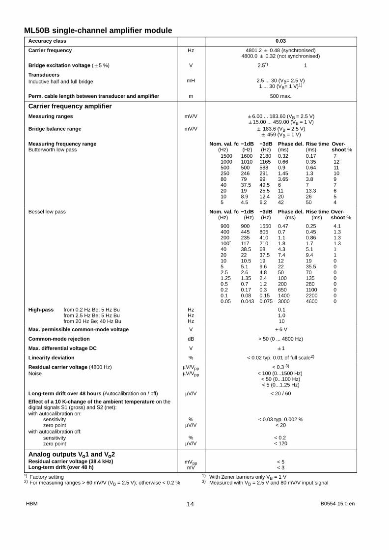
ML50B single-channel amplifier moduleAccuracy class 0.03
Carrier frequency Hz 4801.2 0.48 (synchronised)4800.0 0.32 (not synchronised)
Bridge excitation voltage (5 %) V 2.5*) 1
TransducersInductive half and full bridge mH 2.5 ... 30 (VB= 2.5 V)
1 ... 30 (VB= 1 V)1)
Perm. cable length between transducer and amplifier m 500 max.
Carrier frequency amplifierMeasuring ranges mV/V 6.00 ... 183.60 (VB = 2.5 V)
15.00 ... 459.00 (VB = 1 V)Bridge balance range mV/V 183.6 (VB = 2.5 V)
459 (VB = 1 V)
Measuring frequency rangeButterworth low pass
Nom. val. fc −1dB −3dB Phase del. Rise time Over- (Hz) (Hz) (Hz) (ms) (ms) shoot %
1500 1600 2180 0.32 0.17 71000 1010 1165 0.66 0.35 12500 500 588 0.9 0.64 11250 246 291 1.45 1.3 1080 79 99 3.65 3.8 940 37.5 49.5 6 7 720 19 25.5 11 13.3 610 8.9 12.4 20 26 55 4.5 6.2 42 50 4
Bessel low pass Nom. val. fc −1dB −3dB Phase del. Rise time Over- (Hz) (Hz) (Hz) (ms) (ms) shoot %
900 900 1550 0.47 0.25 4.1400 445 805 0.7 0.45 1.3200 235 410 1.1 0.86 1.3100* 117 210 1.8 1.7 1.340 38.5 68 4.3 5.1 120 22 37.5 7.4 9.4 110 10.5 19 12 19 05 5.1 9.6 22 35.5 02.5 2.6 4.8 50 70 01.25 1.35 2.4 100 135 00.5 0.7 1.2 200 280 00.2 0.17 0.3 650 1100 00.1 0.08 0.15 1400 2200 00.05 0.043 0.075 3000 4600 0
High-pass from 0.2 Hz Be; 5 Hz Bufrom 2.5 Hz Be; 5 Hz Bufrom 20 Hz Be; 40 Hz Bu
HzHzHz
0.11.010
Max. permissible common-mode voltage V 6 V
Common-mode rejection dB > 50 (0 ... 4800 Hz)
Max. differential voltage DC V 1
Linearity deviation % < 0.02 typ. 0.01 of full scale2)
Residual carrier voltage (4800 Hz)Noise
µV/VppµV/Vpp
< 0.3 3)
< 100 (0...1500 Hz) < 50 (0...100 Hz)< 5 (0...1.25 Hz)
Long-term drift over 48 hours (Autocalibration on / off) µV/V < 20 / 60
Effect of a 10 K-change of the ambient temperature on thedigital signals S1 (gross) and S2 (net):with autocalibration on:
sensitivityzero point
with autocalibration off:sensitivityzero point
%µV/V
%µV/V
< 0.03 typ. 0.002 %< 20
< 0.2 < 120
Analog outputs Vo1 and Vo2Residual carrier voltage (38.4 kHz)Long-term drift (over 48 h)
mVppmV
< 5< 3
*) Factory setting 1) With Zener barriers only VB = 1 V2) For measuring ranges > 60 mV/V (VB = 2.5 V); otherwise < 0.2 % 3) Measured with VB = 2.5 V and 80 mV/V input signal
B0554-15.0 enHBM 14
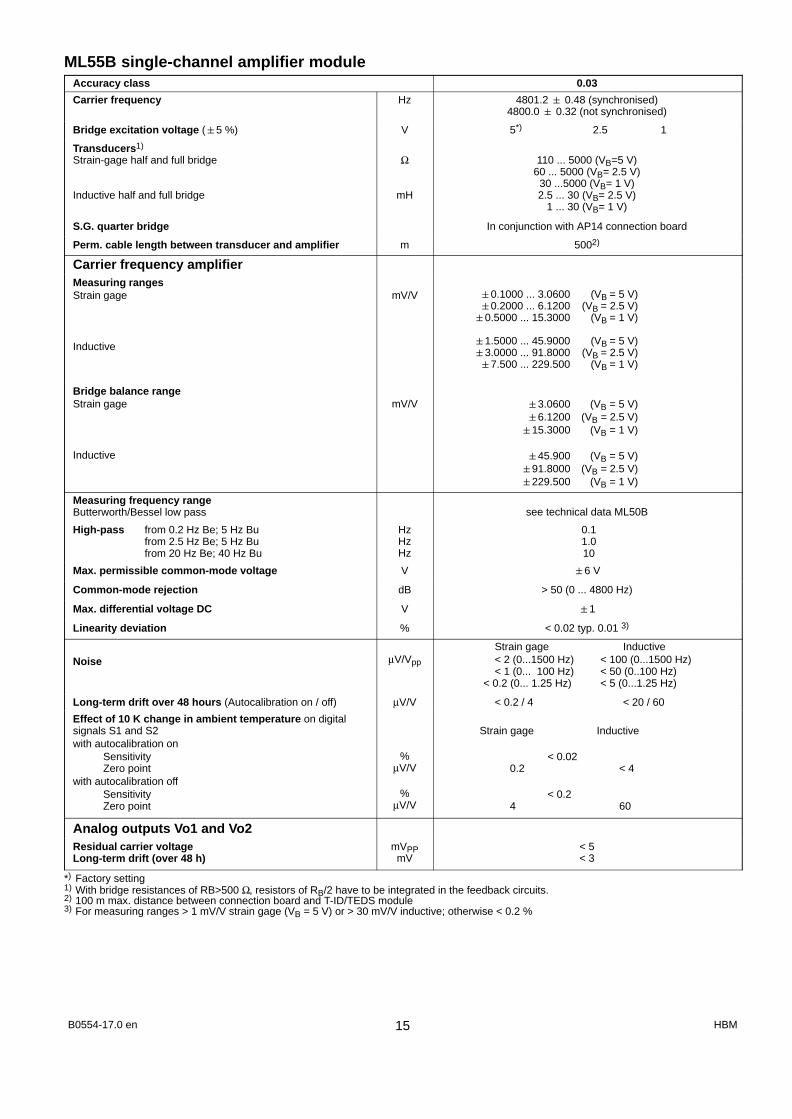
ML55B single-channel amplifier moduleAccuracy class 0.03
Carrier frequency Hz 4801.2 0.48 (synchronised)4800.0 0.32 (not synchronised)
Bridge excitation voltage (5 %) V 5*) 2.5 1
Transducers1)
Strain-gage half and full bridge
Inductive half and full bridge
Ω
mH
110 ... 5000 (VB=5 V)60 ... 5000 (VB= 2.5 V)
30 ...5000 (VB= 1 V)2.5 ... 30 (VB= 2.5 V)
1 ... 30 (VB= 1 V)
S.G. quarter bridge In conjunction with AP14 connection board
Perm. cable length between transducer and amplifier m 5002)
Carrier frequency amplifierMeasuring rangesStrain gage
Inductive
mV/V 0.1000 ... 3.0600 (VB = 5 V)0.2000 ... 6.1200 (VB = 2.5 V)
0.5000 ... 15.3000 (VB = 1 V)
1.5000 ... 45.9000 (VB = 5 V)3.0000 ... 91.8000 (VB = 2.5 V)7.500 ... 229.500 (VB = 1 V)
Bridge balance rangeStrain gage
Inductive
mV/V 3.0600 (VB = 5 V)6.1200 (VB = 2.5 V)
15.3000 (VB = 1 V)
45.900 (VB = 5 V)91.8000 (VB = 2.5 V)229.500 (VB = 1 V)
Measuring frequency rangeButterworth/Bessel low pass see technical data ML50B
High-pass from 0.2 Hz Be; 5 Hz Bufrom 2.5 Hz Be; 5 Hz Bufrom 20 Hz Be; 40 Hz Bu
HzHzHz
0.11.010
Max. permissible common-mode voltage V 6 V
Common-mode rejection dB > 50 (0 ... 4800 Hz)
Max. differential voltage DC V 1
Linearity deviation % < 0.02 typ. 0.01 3)
Noise µV/Vpp
Strain gage Inductive < 2 (0...1500 Hz) < 100 (0...1500 Hz)
< 1 (0... 100 Hz) < 50 (0..100 Hz)< 0.2 (0... 1.25 Hz) < 5 (0...1.25 Hz)
Long-term drift over 48 hours (Autocalibration on / off) µV/V < 0.2 / 4 < 20 / 60
Effect of 10 K change in ambient temperature on digitalsignals S1 and S2with autocalibration on
SensitivityZero point
with autocalibration offSensitivityZero point
%µV/V
%µV/V
Strain gage Inductive
< 0.02 0.2 < 4
< 0.2 4 60
Analog outputs Vo1 and Vo2Residual carrier voltageLong-term drift (over 48 h)
mVPPmV
< 5< 3
*) Factory setting1) With bridge resistances of RB>500 Ω, resistors of RB/2 have to be integrated in the feedback circuits.2) 100 m max. distance between connection board and T-ID/TEDS module3) For measuring ranges > 1 mV/V strain gage (VB = 5 V) or > 30 mV/V inductive; otherwise < 0.2 %
B0554-17.0 en HBM15

ML55BS6 single-channel amplifier moduleAccuracy class 0.03
Carrier frequency Hz9602.4 0.96 (synchronised)
9600.0 0.32 (not synchronised)
Bridge excitation voltage (5 %) V 5*) 2.5 1
TransducersStrain-gage half and full bridge
Inductive half and full bridge
Absolute calibration accuracy
Ω
mH
%
110 ... 5000 (VB=5 V)60 ... 5000 (VB= 2.5 V)
30 ...5000 (VB= 1 V)2.5 ... 20 (VB= 2.5 V)
6 ... 19 (VB= 1 V)better 0.5
Perm. cable length between transducer and amplifier m 5001) max.
Carrier frequency amplifierMeasuring rangesStrain gage
Inductive
mV/V 0.1000 ... 3.0600 (VB = 5 V)0.2000 ... 6.1200 (VB = 2.5 V)0.5000 ... 15.3000 (VB = 1 V)
1.5000 ... 45.9000 (VB = 5 V)3.0000 ... 91.8000 (VB = 2.5 V)7.500 ... 229.500 (VB = 1 V)
Bridge balance rangeStrain gage
Inductive
mV/V 3.0600 (VB = 5 V)6.1200 (VB = 2.5 V)15.3000(VB = 1 V)
45.900 (VB = 5 V)91.8000(VB = 2.5 V)229.500(VB = 1 V)
Measuring frequency rangeButterworth low pass
Nom. val. fc −1dB −3dB Phase del. Rise time Over- (Hz) (Hz) (Hz) (ms) (ms) shoot %
3000 3100 3600 0.33 0.13 161000 1010 1165 0.66 0.35 12500 500 588 0.9 0.64 11250 246 291 1.45 1.3 1080 79 99 3.65 3.8 940 37.5 49.5 6 7 720 19 25.5 11 13.3 610 8.9 12.4 20 26 55 4.5 6.2 42 50 4
Bessel low pass Nom. val. fc −1dB −3dB Phase del. Rise time Over- (Hz) (Hz) (Hz) (ms) (ms) shoot %
900 900 1550 0.47 0.25 4.1400 445 805 0.7 0.45 1.3200 235 410 1.1 0.86 1.3100*) 117 210 1.8 1.7 1.340 38.5 68 4.3 5.1 120 22 37.5 7.4 9.4 110 10.5 19 12 19 05 5.1 9.6 22 35.5 02.5 2.6 4.8 50 70 01.25 1.35 2.4 100 135 00.5 0.7 1.2 200 280 00.2 0.17 0.3 650 1100 00.1 0.08 0.15 1400 2200 00.05 0.043 0.075 3000 4600 0
High-pass from 0.2 Hz Be; 5 Hz Bufrom 2.5 Hz Be; 5 Hz Bufrom 20 Hz Be; 40 Hz Bu
HzHzHz
0.11.010
*) Factory setting1) 100 m max. distance between connection board and T-ID/TEDS module
B0554-15.0 enHBM 16

ML55BS6 single-channel amplifier module (continued)Max. permissible common-mode voltage V 6 V
Common-mode rejection dB > 77 (0 ... 9600 Hz)
Max. differential voltage DC V 1
Linearity deviation % < 0.02 typ. 0.011)
Noise µV/Vpp
Strain gage Inductive< 2 (0...1500 Hz) < 100 (0...1500 Hz)< 1 (0...100 Hz) < 50 (0...100 Hz)
< 0.2 (0...1.25 Hz) < 5 (0...1.25 Hz)
Long-term drift over 48 hours (Autocalibration on / off) µV/V < 0.2 / 0.4 < 20 / 60
Effect of a 10 K-change of the ambient temperature on thedigital signals S1 (gross) and S2 (net):with autocalibration on:
sensitivityzero point
with autocalibration off:sensitivityzero point
%µV/V
%µV/V
Strain gage Inductive
< 0.020.2 < 20
< 0.24 60
Analog outputs Vo1 and Vo2Residual carrier voltageLong-term drift (over 48 h)
mVppmV
< 6< 3
1) For measuring ranges > 1 mV/V strain gage (VB = 5 V) or > 30 mV/V inductive; otherwise < 0.2 %
B0554-17.0 en HBM17

ML60B single-channel amplifier moduleAccuracy class 0.01
Input signalsFrequency F1Signal of the direction of rotation F2Zero indexTransducer error (only with AP01i)
Input level0.1 ... 30 Vp (with control amplifier) or CMOS−level0.1 ... 30 Vp (with control amplifier) or CMOS−levelCMOS−levelCMOS−level
Transducers that can be connectedHBM torque transducers with AP07
with AP17Frequency signal sources with square wave or sinusoidalvoltage, incremental transducers kHz
T3...FN/FNA, T10F−KF1T10F−SF1, T10F−SU2
0.0001 ... 1000
Perm. cable length between transducer and amplifier m 70
Input level5V adjusted100mV adjusted (automatic gain control)
VpVp
5...300.1...30
Input impedance kW typ. 20
Detection of the direction of rotation via additional frequency signal (phase-shifted by 90°)
Measuring ranges Frequency measurement
Pulse counting
Hz
Pulses
100...20001 000 ... 20 000
10 000... 200 000100 000 ... 1 000 000
100 ... 1 000 000
Maximum pulse rate with pulse countingZero-point balancing range
Measuring ranges up to 2 kHzMeasuring ranges up to 20 kHzMeasuring ranges up to 200 kHzMeasuring ranges up to 1 MHz
Noise (10 kHz input signal) Filter Off1 kHz LP−Filter, Butterworth100 Hz LP−Filter, Bessel
Input filter
Pulses/s
HzHzHzHzHzHzHz
1 000 000
−2000 ...+2000−20 000... +20 000
−200 000 ... +200 000−1 000 000 ... +1 000 000
3 1 0.2
Glitch filter, can be switched on
Measuring frequency range
Without filterButterworth low pass
Nom.val. fc –1dB –3dB Phase del. Rise time Over− (Hz) (Hz) (Hz) (ms) (ms) shoot %
− 2500 3100 0.4 0.12 82000 2000 2400 0.5 0.18 101000 1000 1200 0.8 0.35 8500 470 570 0.9 0.70 11250 246 291 1.45 1.3 1080 79 99 3.65 3.8 940 37.5 49.5 6 7 720 19 25.5 11 13.3 610 8.9 12.4 20 26 55 4.5 6.2 42 50 4
Bessel low pass Nom.val. fc –1dB –3dB Phase del. Rise time Over− (Hz) (Hz) (Hz) (ms) (ms) shoot %
900 900 1800 0.6 0.35 0400 400 800 0.8 0.52 1.0200 235 410 1.1 0.86 1.3
100*) 117 210 1.8 1.7 1.340 38.5 68 4.3 5.1 120 22 37.5 7.4 9.4 110 10.5 19 12 19 05 5.1 9.6 22 35.5 0
2.5 2.6 4.8 50 70 01.25 1.35 2.4 100 135 00.5 0.7 1.2 200 280 00.2 0.17 0.3 650 1100 00.1 0.08 0.15 1400 2200 0
0.05 0.043 0.075 3000 4600 0High-pass from 0.2 Hz Be; 5 Hz Bu
from 2.5 Hz Be; 5 Hz Bufrom 20 Hz Be; 40 Hz Bu
HzHzHz
0.11.010
Absolute calibration accuracy % 0.005Long-term drift over 90 d % <0.005Effect of a 10 K-change of the ambient temperature on thedigital signals S1 (gross) and S2 (net): % 0.005
Analog outputs Vo1 and Vo2Residual carrier voltage (38.4 kHz)Long-term drift (over 48 h)
mVppmV
< 5< 3
*) Factory setting
B0554-15.0 enHBM 18

AP 02AP01i
AP03i
AP07/1
AP08
Connection boards for single-channel amplifiers
AP01i (connection board with D-female receptacle)
Width mm 20.3 (4 divs)
Transducer connection D15 female receptacle, DA-15P 1)
Output-signal connection D25 female receptacle, DB-25P 2)
Option 2x EM001; 2x RM001 with AP02
Weight, approx. kg 0.3
AP02 (Relay module)
Width mm 20.3 (4 divs)
Output-signal connection D37 female receptacle, DC-37P 3)
Option 2x RM001
Weight, approx. kg 0.3
AP03i (connection board with MS-female device receptacle)
Width mm 40.6 (8 divs)
Transducer connection 7-pin MS-female receptacle, MS3106A 16S-1P 4)
Output-signal connection D25 female receptacle, DB-25P 2)
Option 2x EM001, 2x RM001 with AP02
Weight, approx. kg 0.3
AP07/1 for connection of T3..FNA and T10.. torque transducers
Width mm 40.6 (8 divs)
Torque-transducer supplysupply during measurementsupply for calibrationFrequency
VppVppkHz
5481
15 ... 20
Transducer connection 7-pin MS-female receptacle, MS3106A 16S-1P 4)
Output-signal connection D25 female receptacle, DB-25P 2)
Option EM001; RM001
Weight, approx. kg 0.5
AP08 for piezoelectric transducers
Width mm 20.3 (4 divs)
ConnectionsTransducerAnalog output, control signals
BNC-female receptacle, isolatedD25 female receptacle
Range capacitors CgMeasuring ranges
nFpC
0.130...100
150...1000
10500...10000
1005000...100000
AccuracyMeasuring range ≤ 100pCMeasuring range ≥ 100pC
Measuring frequency range≤ 1000pC/Cg=100pF, 1nF10000pC/Cg=10nF100000pC/Cg=100nF
Linearity deviation
%%
kHzkHzkHz%
≤2.5≤1
100 (−1 dB)15 (−1 dB)1.5 (−1 dB)
0.25 full scale
Low pass filter − according to the data sheets of ML01B and ML10B
Option − 1xEM001; 2xRM001 with AP02
1) HBM-order number 3-3312.01822) HBM-order number 2-9278.02933) HBM-order number 2-9278.02944) HBM-order number 1-MS3106 PEMV
B0554-17.0 en HBM19

Connection boards for single-channel amplifiers (continued)
AP08 (continued)
Time constant ( t=Cg ⋅ Rg)LongMedium (Rg=100 GΩ)Short (Rg=1 GΩ)
Maximum cable lengthRange capacitor Cg=100pFRange capacitor Cg ≥1nF
−ss
mm
−10...100000.1...100
100200
Zero offset (during zero/measurechangeover)Drift (at 20°C)Effect of a 10K-change of the ambienttemperature
on the sensitivityon the zero point
Operating temperature range
pCpC/s
%%
°C [°F]
<10.1
0.2 full scale0.1 full scale
−20...+60 [−4...+140]
Low pass filter − according to the data sheets of ML01B and ML10B
Weight, approx. kg 0.3
AP09 for connection of thermocouples
Width mm 20.3 (4 divs)
Accuracywith 25°Cwith 20 ... 60°C
°C °C
0.31
Transducer connection Terminal screws (0.5...1.5 mm2)
Temperature cold junction Semiconductor temperature-sensor at theterminal screw
Reference-point measuring range °C [°F] −20...+60 [−4...+140]
Option 2x EM001; 2x RM001 with AP02
Weight, approx. kg 0.3
AP11i (connection board with Lemo-female device receptacle)
Width mm 20.3 (4 divs)
Transducer connection 6-pin Lemo FGG.1B.306 1)
Output-signal connection D25 female receptacle, DB-25P 2)
Option 2x EM001; 2xRM001 with AP02
Weight, approx. kg 0.31) HBM order number 3-3312.0126 2) HBM order number 2-9278.0293
AP13i for PLC I/O cards; all inputs and outputs are electrically isolated by optical couplers
Width mm 20.3 (4 divs)
Outputs (short-circuit proof; protective circuit for inductive loads)
NumberSeparate ground systemsNominal (rated) voltage (ext. supply)Permissible voltage rangeOutput currentShort-circuit currentPerm. short-circuit durationSwitching frequency on resistive load
VVAA
Hz
5224
6...48max. 0.5
0.8no limit
max. 500
Input/Output D-female receptacle 15/25-pin
Option 1x EM001
Inputs
NumberSeparate ground systemsInput voltage for
Low-levelHigh-level
Input current at 24 VCurrent consumption
internal 5 Vexternal 24 V
Maximum power lossPerm. short-circuit duration
VV
mA
mAmAW
84
< 5> 1012
137.5 (without load)
10.5unlimited
Permissible lead length m approx. 1000
Weight, approx. kg 0.3
AP11iAP09
AP08
AP13i
B0554-15.0 enHBM 20

Connection boards for single-channel amplifiers (continued)
AP14 for Single S.G.
WidthOptions
mm−
20.3 (4 divs)1 EM001 output stage module; 2x RM001 with AP02
Accuracy classFull bridgeHalf bridgeQuarter bridge
%%%
0.10.50.5
Transducers that can be connected
Amplifier modules that can be con-nectedConnections
TransducerAnalog output, control signals
strain gage half and full bridges, single strain gages in 3-wire or 4-wire-technique
ML10B, ML30B, ML55B
D15 female receptacle, DB25PD25 female receptacle, DB25P
Internal completion resistors Ω 120, 350, 700
Max. perm. cable length between transducer and connection board m 500
Linearity deviation % 0.05
Measurement frequency range kHz 0...50
Effect of a 10 K change of ambient temperature
on zero pointon measurement sensitivity
%%
Full bridge0.050.05
Quarter, Half bridge0.50.1
Operating temperature range °C [°F] −20...+60 [−4...+140]
Weight, approx. kg 0.3
AP17 for connecting T10F−SF1, T10F−SU2 torque flanges and frequency signals to ML60B
Width mm 20.3 (4 divs)
Transducer connection D15 female receptacle, DA-15P 1)
Analog output/control signals D25 female receptacle DB-25P 2)
Nominal (rated) temperature range °C [°F] −20 ... +60 [−4 ... +140]
Option 1x EM001, 2xRM001 with AP02
Weight, approx. kg 0.3
Outputs
Transducer supply
Release of calibration signal
V (DC)V (DC)V (DC)V (DC)
+16 (max. 500 mA)3)
−16 (max. 500 mA)3)
+5 (max. 300 mA)3)
approx. 5 (max. 100 mA)
Inputs
Nominal (rated) input voltagesymmetricalasymmetrical
Minimum/maximum voltage swingsymmetricalasymmetrical
Common−mode voltage rangeMaximum input frequency
VPPVPP
VPPV0PV
kHz
105
0.3/143/20
−5 ... +41000 (with ML60B max. 200)
1) HBM order number 3-3312.01822) HBM order number 2-9278.02933) The specified current values are the maximum permissible permanent currents for AP17. The number of con
nection boards per housing is not limited, however, a maximum of four connection boards can be used for the transducer supply (5 V/16 V e.g. for T10F−SF1 torque flange).
AP14
AP17
B0554-17.0 en HBM21

Connection boards for single-channel amplifiers (continued)
AP18i for current-fed piezoelectric transducers
Accuracy class % 1
Width mm 20.3 (4 divs)
Transducer excitation mA 2.5...20 (adjustable) 4 (factory setting)
Current-source dynamic impedance kΩ 30 typ.
Input voltage range V 12 9 (3...21 V)
Load resistance kΩ >5
Input sensitivity V 0.1; 1V; 10V (0.05 dB)
Frequency responseInput sensitivity 1 V for -1 dB
for -3 dBInput sensitivity 0.1 V for -1 dB
for -3 dBInput sensitivity 10 V for -1 dB
for -3 dB
HzHzHzHzHzHz
0.18...150000.10...250000.18...170000.10...310000.18...220000.10...43000
Effect of a 10 K change in ambient temperature % 0.04 of full scale
Noise referred to the input (2 Hz...22.4 kHz)Input sensitivity 0.1 VInput sensitivity 1 VInput sensitivity 10 V
µVmsµVmsµVms
303075
Distortion at 1 kHzat 8 kHz
dBdB
−70 (typ.)−60 (typ.)
Option Current output stage
Weight, approx. kg 0.3
AP18i
B0554-15.0 enHBM 22

ML455 multi-channel amplifierML455 + Connection board AP455i/AP455iS6
Accuracy class 0.05
Accuracy % (0.05 of measured value+0.05 of full scale value)
Carrier frequency Hz 4801.20.48
Bridge excitation voltage (5%) V 2.5
Connectable transducers*) in 6- (5) wire technique Strain-gage half- or full bridgeInductive half- or full bridge
LVDT
Permissible cable length between transducer and con-nection board5) m 100
Measuring ranges
Strain-gage mV/V 4
Inductive mV/V 100
LVDT mV/V 1000
Transducer impedance
Strain-gage half- or full bridge W 120 ... 1000
Inductive half- or full bridge, LVDT mH 4 ... 330
Noise at 25°C [77°F]
Butterworth/Bessel1000 Hz/200 Hz80 Hz/40 Hz20 Hz/5 Hz5 Hz/1.25 Hz
mV/VmV/VmV/VmV/V
Strain-gage Inductive LVDT< 3 < 30 < 140< 0.5 < 3 < 28< 0.2 < 1.5 < 14< 0.1 < 0.5 < 6
Linearity deviation % < 0.02
Effect of a 10K−change of the ambient temperature Autocal on Autocal off
on sensitivityon zero point
%6)
%7)< 0.01< 0.005
< 0.03< 0.01
Operating temperature range °C [°F] −20...+60 [−4 ... +140]
Transducer connectionAP455iAP455iS6
4x15-pin Sub-D6−pin LemoR FGG.1B.3068)
Width mm 20.3 (4 divs)*) The transducer type can be selected separately for each of the four subchannels5) Use cable twisted and shielded in pairs with outer shield (e.g. HBM-no. 4−3301.0071)6) Of measured value7) Of full scale value8) HBM order number 3−3312.0126
ML455 AP455i
ML 455
AP455iS6
AP455iS6
Subchannel 1
Subchannel 2
Subchannel 3
Subchannel 4
B0554-17.0 en HBM23

ML460 multi-channel amplifier moduleML460 + connection board AP460i
Accuracy class % 0.011)
Connectable transducers
HBM torque transducers2) T4WA-S3, T3...FN/FNA, T10F...−KF1, T10F...−SF1,T10F...−SU2
Frequency signal sources with square-wave orsine-wave voltage, incremental transducers
kHz 0.0001...500
Inductive rotation speed measuring devices (T-R coils)using input filtering
kHz 0.5...200
Measuring ranges
Frequency measurement kHz 0...20...200...2000...500
Accuracy, related to full scale value % 0.01
Pulse counting Pulses 100...1 000 000
Maximum impulse rate when pulse counting Imp./s 500 000
Precision Kimp 0.001
PWM carrier frequency Hz 1...10 000
Precision %/kHz 0.05
Pulse duration ms 0 ... 2500
Precision ms 0.001
Input frequency range Hz 0.25 ... 10 000
Channel properties
Number of subchannels 4
Class accuracy 0.01
Signals per subchannelF1F2Zero index
Frequency, pulse or PWM signal±90° phase shift relative to F1 (direction detection)
For detection of zero position in pulse counting
Electrical separation of all inputs from one another andfrom MGC ground V Typically 500 V
Input frequency range kHz 0...500
Nominal (rated) temperature range _C [°F] −20 ...+ 60 [−4 ... +140]
Operating temperature range _C [°F] −20 ...+ 60 [−4 ... +140]
Storage temperature range _C [°F] −25 ... +70 [−13 ... +158]
Input signals
Direct inputs, difference signals
Input voltage range VPP 0.4 ... 30
Direct inputs, bipolar
Input voltage range VPP 0.4 ... 30
Direct inputs, unipolar
Input voltage range V 5...30
Minimum pulse width ms 3
Input for inductive transducer, filtered (F1 signals only)
Required minimum input voltage (peak-to-peak)500 Hz1 kHz10 kHz25 kHz50 kHz75 kHz100 kHz125 kHz150 kHz175 kHz200 kHz
50 mV100 mV750 mV
1 V1.5 V2 V
2.5 V3 V4 V5 V7 V
Maximum input voltage V 30
Input resistance F1 signal kΩ approx. 61) 0.05 in the case of PWM2) This torque transducers are not fed by the connection board AP460i!
B0554-15.0 enHBM 24

ML460 multi-channel amplifier module (continued)Transducer excitation
Maximum current per channel5 V8 V16 V
16 modules/device 1 module/device10 mA 160 mA62.5 mA 600 mA62.5 mA 600 mA
Measuring frequency range Nom. val. fc –1dB –3dB Phase del. Rise time Overshoot
(Hz) (Hz) (Hz) (ms) (ms) %
Without filter − 740 1750 1 <0,6 0
Low−Pass with Butterworth–Characteristic 500 450 550 1,5 1 9,4250 250 290 2,5 2,1 1280 83 99 5 6,2 8,540 41 49,5 7,5 13 7,820 20 25,5 12 24 710 9 12,4 25 50 4,75 5 6,5 46 100 4,7
Low−Pass with Bessel–Characteristic Nom. val. fc –1dB –3dB Phase del. Rise time Overshoot
(Hz) (Hz) (Hz) (ms) (ms) %400 380 650 1,4 1 1200 235 380 1,5 1,75 1
100*) 125 210 2,6 3 240 43 70 5,2 7,5 120 24 40 7,4 15 110 11 18 15,7 31 05 4 10 27 55 0
2,5 2,6 4,8 53 125 01,25 1,35 2,4 104 210 00,5 0,7 1,2 195 450 00,2 0,17 0,3 730 2000 00,1 0,08 0,15 1480 3700 0
0,05 0,04 0,075 3000 7500 0
Mechanical
Card format mm Europe 100 x 160
Width mm 20.3 (4 divs)
Connections Lemo 1B 10−pin EXG.1B.310.HLN
Designation of suitable male connector(Manufacturer Lemo))
Fixed plug (1st letter in model desig.) : FKey (3rd letter in model desig.) : G
Series: 1BType: 310
Example: FGG.1B.310.CLAD62(Bold characters must be selected)
B0554-17.0 en HBM25

ML460 multi-channel module and AP460i connection board
ML460 AP460i
Subchannel 1
Subchannel 2
Subchannel 3
Subchannel 4
AP460iML 460
CHANERROROVER-LOAD
1
2
3
4
1
2
3
4
SI-GNAL
B0554-15.0 enHBM 26

ML801B multi-channel amplifierML801B + connection board AP8011) AP8092) AP4093) AP8354)
Accuracy class 0.05 0.2 0.05
Number of measuring points 8 4 8
Transducers 10 Vsymmetrical
Thermo-couples
Type K, J, T,E, N, B, R
Thermo-couples
Type K, J, T, E,N, S, B, R,
Individual in-puts electrically
isolated
Pt100 4−wirecircuit
Width mm 20.3 (4divs)
Maximum sampling rate per channel Hz 2400 (8 subchannels), 4800 (4 subchannels), 9600 (2 subchannels)5)
Measuring frequency range kHz 0 ... 1
Effective resolution Bit 20
Maximum permissible input voltage and common-modevoltage V 50 10 50 −
Absolute calibration deviation % 0.05
with cold junction K − 0.5 −
FilterButterworth low pass HD fg max
Nominal −1dB −3dB Internal(rated) Sampling rate6)
(Hz) (Hz) (Hz) (Hz)1000 1189 1518 9600500 523 691 9600250 253 322 9600200 203 265 960080 78 103 9600
1000 1206 1516 4800500 613 816 4800250 255 327 4800200 203 264 480080 78 102 4800
250 312 413 2400200 226 300 240080 82 109 240040 41 54 120020 21 27 60010 10 13 3005 5,3 7 150
Bessel low pass HD fg maxNominal −1dB −3dB Internal
(rated) Sampling rate6)
(Hz) (Hz) (Hz) (Hz)200 259 448 2400100 102 184 240040 41 75 240020 20 36 240010 10 18 24005 5 9 1200
2,5 2,5 4,5 6001 1 1,8 300
0,5 0,5 0,9 1500,2 0,21 0,38 750,1 0,1 0,19 37,5
0,05 0,051 0,094 18,7
1) Connection plug on customer side: e. g. Phoenix Contact MC1.5/3-ST-3.5; Art. No. 1840379(Connection plug for AP801S6: Lemo FGG.0B.304.CLAD52)
2) No line break recognition3) Two AP409 or two AP402i can be operated with one ML801B4) Connector plug provided by customer: Lemo FFA.0S.304.CLA5) The number of subchannels can be changed by the MGCplus-setup-assistent or the MGCplus firmware loader6) The signals are converted internally at 38.4 kHz independent of the number of subchannels adjusted. Implementation of digital filters requires
a reduction of the sampling rate (through repeated averaging and subsampling). This reduced sampling rate is called ”internal sampling rate”.
B0554-17.0 en HBM27

ML801B+Connection board AP801 AP809 AP409 AP835
FiltreButterworth low pass compatible fg max
Nominal −1dB −3dB Internal(rated) Sampling rate
(Hz) (Hz) (Hz) (Hz)1000 1076 1282 4800500 596 798 4800250 279 345 2400200 214 266 240080 78,9 103 240040 38,7 51,8 240020 19,5 27,2 240010 9,36 13,2 24005 4,37 6,4 1200
Bessel low pass compatible fg maxNominal −1dB −3dB Internal
(rated) Sampling rate(Hz) (Hz) (Hz) (Hz)200 322 571 2400100 125 216 240040 41 70 240020 21 37 240010 11 19 24005 5,5 9,6 2400
2,5 2,7 4,8 12001 1,36 2,4 600
0,5 0,68 1,2 3000,2 0,186 0,186 750,1 0,093 0,158 37,5
0,05 0,047 0,079 18,7
Input for voltage measurement
Input signal range VmV
−10.5...+10.5−80...+80 −80...+80
−
Zero offset VmV
−10.5...+10.5−80...+80 −80...+80
−
Internal resistance of the signal voltage source kW < 1.0 −
Input resistance symmetrical/asymmetrical kW 500/250 2000/1000 1000 −
Noise rel. to input with filter setting 1.25 Hz mVpp < 50 < 0.5 < 2 −
Long-term drift over 48 hours (Autocalibration on/off) mV 0.8/1.5 0.01/0.02 0.02/0.05 −
Linearity deviation % <0.03; typ. 0.01
<0.03; typ. 0.01
<0.06; typ. 0.03
−
Transducer supply7) (AP801S6 only)Transducer supply voltage (must in each case be selectedfor all channels collectively)Max. output current for external transducers
VmA
8/1650
−−
−−
−−
7) With MGCplus, a maximum of 2 A may be drawn for transducer supply.
B0554-15.0 enHBM 28

ML801B multi-channel amplifier (continued)ML801B + Connection board AP801 AP809 AP409 AP835
Input for thermocouples
Linearisation error °C − < 0.06 < 0.25 (K, J, T, E, N) −
°C − − < 0.6 (S, B, R) −
Linearisation range NiCr−Ni (K) °C − −158...+1414 −191...+1414 −
Fe−CuNi (J) °C − −167...+1192 −190...+1192 −
Cu−CuNi (T) °C − −210...+393 −237...+393 −
NiCr−CuNi (E) °C − −161...+1005 −205...+1005 −
NiCrSi−NiSi (N) °C − −186...+1300 −219...+1300 −
Pt10Rh−Pt (S) °C − − −50...+1755 −
Pt30Rh−Pt6Rh (B) °C − +570...+1814 +160...+1814 −
Pt13Rh−Pt (R) °C − +178...+1769 −50...+1769 −
Temperature range of cold junction °C − −20...+60 −
Long−term drift over 48 h with/without autocalibration
Type K, J, T, E, N K − 0.2/0.4 0.5/1 −
Type B, R K − 1.0/2.0 2/3 −
Type S K − − 2/3 −
Noise with 1.25 Hz filter
Type K, J, T, E, N K − < 0.1 < 0.1 −
Type B, R K − < 0.3 < 0.3 −
Type S K − − < 0.3 −
Input for Pt100
Measuring range W − − − 500
Linearisation error °C − − − < 0.02
Linearisation range °C − − − −200 ... +848
Noise voltage with 1.25 Hz filter mWpp − − − 2
Measuring current mA − − − 0.5
Permissible cable length between transducer and amplifier m − − − 300
Linearity deviation K − − − 0.1
Long−term drift over 48h with autocalibration mW − − − < 301) 100 m max. distance between connection board and T-ID/TEDS module
ML801B + Connection board AP401
Accuracy class % 0.1
Measuring range V 10
Max. common mode input voltage (to housing/ground) V 45
Max. differential input voltage V 70
Input impedance MW 20
Common−mode rejection(with 50 Hz, 20 VPP)(with DC 10 V)
typ. 75min. 100
Measurement frequency range Hz 1000 (−1 dB)
Linearity deviation % 0.03
Effect of a 10K−change of the ambient temperatureon zero point (related to full scale)
Autocal onAutocal off
on sensitivityAutocal onAutocal off
%%
%%
max. 0.02max. 0.05
max. 0.02max. 0.05
ESD resistance channel to housing/ground V (DC) 400
ESD resistance channel to channel V (DC) 400
Transducer connection 4−pole female connector, compatible to Lemo Serie S, Size 0, contact arragement 304,
fitting connector: e.g. FFA 0S 304 CLAC52 (Lemo)
Width mm 20.3 (4 divs)
Operating temperature range °C [°F] −20...+60 [−4...+140]
B0554-17.0 en HBM29

ML801B multi-channel amplifier (continued)
ML801B + Connection board AP402i
Accuracy class % 0.1
Measuring ranges VmA
1, 10, 6020
Potential separated measuring inputs V DC typ. 500
Max. common mode input voltageto ( housing / ground) V 100
Max. differential input voltage V 70
Input impendanceMeasuring ranges 1V, 10VMeasuring range 60VMeasuring range 20mA
MΩMΩΩ
100.645
Common−mode rejection(with 50 Hz, 20Vpp)(with DC 10V)
dBdB
typ. 75min. 100
Mesurement frequency range Hz 1000 (−1dB)
Linearity variation % 0.03
Noise voltageFilter characteristicsMeasuring range 1VMeasuring range 10VMeasuring range 60VMeasuring range 20mA greater than 45 Ohm
µVppµVppµVppµVpp
5 Hz Bessel / 500 Hz Butterworth< 40 / < 300
< 400 / < 3000< 2400 / < 18000
< 100 / < 500
Effect of a 10K−change of the ambient temperature onon zero point(related to full scale)Autocal onAutocal offon sensitivityAutocal onAutocal off
%%
%%
max. 0.02max. 0.075
max. 0.05 (Measuring range 10V: max. 0.02)max. 0.1
Transducer connection 6−pin socket, compatible with Lemo S series, size 0Adapted plugs:
e.g.: FGG.1B.306.CLA.441.D421)
FGG.1B.306.CLA.441.D62
Transducer supply
current carrying capacitypotential seperation
V DCmA−
Can be adjusted through jumper field:open, +5, +8 or +16 (for all subchannels)max. 100 (for all subchannels together)
no
Transducer indentificationmax. distance between TEDS module and AP402ipotential seperation
mTEDS−capable (external TEDS modules only)
100no
Nominal (rated) temperature range _C [_F] −20 ... +60 [−4...+140]
Operating temperature range _C [_F] −20 ... +60 [−4...+140]
Storage temperature range _C [_F] −25 ... +70 [−13...+158]
Width mm 20.3 (4 divs)
1) HBM-order number 3-3312.0126
B0554-15.0 enHBM 30

ML801B multi-channel amplifier (continued)ML801B + Connection board AP418i
Accuracy class % 1.0
Connectable transducers*) 4 current−fed piezoelectric transducer (e.g. Deltatront)
Transducer identification T-ID and TEDS compatible
Transducer excitation mA 4
Input voltage range V 2 ... 20
Measuring ranges V 0.05; 0.5; 5
Measurement frequency range Hz 1000 (−1 dB)
Lower limit frequency (−3 dB) Hz 0.72
Linearity deviation % 0.05
NoiseFilter characteristics
Measuring range 0.05 VMeasuring range 0.5 VMeasuring range 5 V
VPPVPPVPP
5 Hz Bessel/500 Hz Butterworth< 25 m/< 60 m
< 25 m/< 0.35 m< 100 m/< 3.5 m
Effect of a 10K−change of the ambient temperature Measuring range 0.05 V Measuring range 0.5 V und 5 V
on zero point (related to full scale) % 0.1 0.03
Width mm 20.3 (4 divs)
Operating temperature range °C [°F] −20...+60 [−4...+140]*) If the transducer connection cable is used outside of closed rooms or if the transducer connection cable is longer than 30 m, then this cable
must be protected against high voltage with an additional, separately grounded shield. This can be achieved laying the cable in a metallic pipeor by using double shielded cables, where the external shield near by the connection board must be grounded (connect to ground or groundwire). For this purpose HBM recommend to use Triaxial cables.
ML801B + Connection board AP810i
Accuracy class % 0.1
Transducers that can be connected 8 S.G. half or full bridges
Excitation voltage (DC) V 10; 5; 2.5; 0.5
Transducer resistance at VBRmin (full bridge)Rmax
WW
10 V 5 V 2.5 V 0.5 V330 160 120 120
4000
Measuring ranges mV/V 4 (VB=10 V)8 (VB=5 V)
16 (VB=2.5 V)80 (VB=0.5 V)
Control signal (Shunt) mV/V approx. 1 (with 350 W S.G. full bridge)approx. 0.5 (with 350 W S.G. half bridge)
Noise at 350 WFilter characteristicsFilter frequency
VB=10VVB=5VVB=2.5VVB=0.5V
Hzmm/mmm/mmm/mmm/m
Bessel/Butterworth1.25/5 40/80 200/500<0.025 <0.15 <1.8<0.05 <0.3 <3.5<0.1 <0.6 <7<0.4 <3 −
Transducer connection D25 female receptacle
Permissible cable length between transducer andconnection board m
200 (100 m max. distance between connection board andT−ID/TEDS module)
Width mm 20.3 (4 divs)
Linearity deviation % 0.05
Measurement frequency range Hz 500 (−1 dB)
Effect of a 10 K−change of the ambient temperature onzero point (related to full scale)on sensitivity
%%
0.050.1
Operating temperature range °C [°F] −20...+60 [−4 ... +140]
B0554-17.0 en HBM31

ML801B multi-channel amplifier (continued)ML801 B+ Connection board AP814Bi
Accuracy class % 0.11)
Transducers that can be connected 8 S.G. quarter bridges in three wire technique
Internal completion resistors W 120, 350, 700, 10002)
Excitation voltage (DC) V 5; 2.5; 1; 0.5
Measuring ranges mV/V 8 (VB=5 V)16 (VB=2.5 V)40 (VB=1 V)80 (VB=0.5 V)
Control signal (Shunt) mV/V approx. 1(at 350 W)
Noise at 350 WFilter characteristicsFilter frequency
VB=5 VVB=2.5 VVB=1 VVB=0.5 V
Hzmm/mmm/mmm/mmm/m
Bessel/Butterworth1.25/5 40/80 200/500<0.05 <0.3 <2.5<0.1 <0.65 <6.5<0.25 <1.5 <13<0.45 <3.5 −
Transducer connection D25 female receptacle
Permissible cable length between transducer andconnection board m 2003)4)
Width mm 20.3 (4 divs)
Linearity deviation % 0.05
Measurement frequency range Hz 500 (−1 dB)
Effect of a 10 K-change of the ambient temperature onzero point (related to full scale)on sensitivity
%%
0.10.1
Operating temperature range °C [°F] −20...+60 [−4 ... +140]1) The effect of errors due to asymmetrical cable resistances is not allowed for in the accuracy class.2) Optional3) Use connection cable of 0.25 mm2 wire cross section.4) 100 m max. distance between connection board and T-ID/TEDS module
ML801B + Connection board AP815i
Accuracy class % 0.15)6)
Transducers that can be connected 8 S.G. full bridges in six wire technique or8 S.G. half bridges in six wire technique or8 S.G. half bridges in five wire technique or
8 S.G. quarter bridges in four wire technique or2 S.G. rosettes
Internal completion resistors W 120, 350, 700, (optional 1000)
Excitation voltage (DC) V 5; 2.5; 1; 0.5
Measuring ranges mV/V 8 (VB=5 V)16 (VB=2.5 V)40 (VB=1 V)80 (VB=0.5 V)
Control signal (Shunt) mV/V 1.0078 0.1 % (at 350 W)
Noise at 350 WFilter characteristicsFilter frequency
VB=5 VVB=2.5 VVB=1 VVB=0.5 V
Hzmm/mmm/mmm/mmm/m
Bessel/Butterworth1.25/5 40/80 200/500<0.1 <0.6 <4<0.2 <1.2 <8<0.5 <3 <20<1 <6 <40
Transducer connection 2 D25 female receptacle (four channels each)
Permissible cable length between transducer andconnection board m 2007)
Width mm 20.3 (4 divs)
Linearity deviation % 0.05
Measurement frequency range Hz 500 (−1 dB)
Effect of a 10 K-change of the ambient temperature onzero point (related to full scale)on sensitivity
%%
0.12)
0.1
Operating temperature range °C [°F] −20...+60 [−4 ... +140]5) 0.2 with irradiation according to EN 6100−4−3:1996 + A1:19986) 0.2 with 5 V−excitation7) 100 m max. distance between connection board and T-ID/TEDS module
B0554-15.0 enHBM 32

ML801B multi-channel amplifier (continued)ML801B + Connection board AP836i
Accuracy class % 0.1
Transducers that can be connected 8 x transducer in 5−wire circuit, 8 x voltageUngrounded active transducers with 5V/10V voltage supplyand voltage output, can be selected individually per channel
Excitation voltage (DC) V 5
Transducer resistanceRminRmax
WW
1905000
Measuring rangesPotentiometric transducersActive transducers1)
mV/VV
50010
NoiseFilter characteristicsFilter frequency
HzmV/V
Bessel/Butterworth1.25/5 40/80 200/500<0.01 <0.05 <0.5
Transducer connection D25 female receptacle
Permissible cable length between transducer andconnection board
m 200 (100 max. distance between connection board and T-ID/TEDS modul)
Width mm 20.3 (4 divs)
Linearity deviation % 0.05
Measuring frequency range Hz 500 (−1 dB)
Effect of a 10 K-change of the ambient temperature onzero point (related to full scale)on sensitivity
%%
0.050.1
Operating temperature range °C [°F] −20...+60 [−4 ... +140]1) Excitation voltage can be adjusted to 2.5 V; 5 V; 10 V through display and control panel or software.
B0554-17.0 en HBM33

Connection boards for multi-channel amplifiers
AP801for 8 DC voltage sources
AP809for 8 thermocouples
AP409for 4 thermocouples
AP835for 8 RTD Pt100
13
14
25
1
13
14
25
1
AP810ifor 8 S.G. half or full bridges
13
14
25
1
AP814Bifor 8 S.G. quarter bridges
in three wire technique
AP836ifor 8 potentiometric
Transducers
13
14
25
1
13
14
25
1
AP801S6for 8 voltage sources
with voltage supply 8V/16V
AP801S6
13
14
25
1
13
14
25
1
AP815ifor 8 S.G. quarter, half-
or full bridges
B0554-15.0 enHBM 34

Connection boards for multi-channel amplifiers
AP418ifor 4 current−fed piezoelectric transducers
(compatible with T-ID and TEDS)
AP401for 4 DC−voltage supplies
(electrically isolated)
AP402iFor 4 DC voltage or current sources(electrically isolated, TEDS capabil-
ity, with 5 V, 8 V, 16 V voltage supply)
B0554-17.0 en HBM35

Programmable plug−in module ML70B1)
Analogue outputs
Max. number of analog outputs 2 (10 with AP78)
Analogue outputs update rate Hz 2400
Nominal (rated) voltage V 10V asymmetrical
Permissible load resistance kΩ >5
Internal resistance Ω < 5
Residual carrier voltage (76.6 kHz) mVPP < 12
Long-term drift (over 48h) mV < 3
Effect of ambient temperature at 10_K:SensitivityZero point
%mV
< 0.08 typically 0.04< 3 typically 2
Programming
Programming language IEC61131−3
Data program memory (volatile) kByte 224
Data program memory (non-volatile) kByte 16
Code program memory (volatile)(2 x available for online change)
kByte 2 x 160
Code program memory (non-volatile) kByte 160
Memory for project sources (non-volatile) kByte 192
Call frequency of the IEC program Hz 2400, synchronized with MGCplus measured-value processing
Number of subchannels 1...128 (set by user)
Effective computer output 75,000 float operations/sor 300,000 integer operations/s
Mechanical
Nominal (rated) temperature range _C [°F] −20 ...+ 60 [−4 ...+140]
Operating temperature range _C [°F] −20 ...+ 60 [−4 ...+140]
Storage temperature range _C [°F] −25 ... +70 [−13 ...+158]
Operating voltages V +14.6 ... +17.0 (<90 mA)−14.6 ... –17.0 (<100 mA)
−7 ... −9 (<10 mA)
Card format mm Europe 100 x 160
Width mm 20.3 (4 divs)
Connector DIN 41612 indirectly
Supported connection boards
Number of controllable connection boards 0, 1 or 2
Supported connection board types AP71 (2 CAN interfaces)AP72 (2 serial interfaces)
AP75 (8 Digital-In, 8 Digital-Out, 24V level)AP78 (8 analog outputs)
AP72 Connection boardInterfaces
Baudrate kBaud 9.6; 19.2; 38.4; 57.6; 115.2
Electrical isolation V Typ. 500
Connector 9−pol.Sub−D female receptacle
Mechanics
Nominal (rated) temperature range _C [°F] −20 ... +60 [−4 ...+140]
Operating temperature range _C [°F] −20 ... +60 [−4 ...+140]
Storage temperature range _C [°F] −25 ... +70 [−13 ...+158]
Nominal (rated) voltages V +5 ... (< 100 mA)
Card dimensions mm 102 x 112
Width mm 20.3 (4 division units)1) Only in systems with CP22, CP32 and CP42 or in systems without a communications processor.
B0554-15.0 enHBM 36

ML70B Programmable module and AP72 Connection board
ML70B AP72
ML70B
Communication card ML71B/ML71BS6 with AP71 Connection board (CANbus)1)
CAN interface
Number of CAN interfaces 2
Protocol CAN 2.0B
Baud rate Baud 10k 20k 50k 125k 250k 500k 1M
Line length m 1000 1000 1000 500 250 100 25
Hardware bus link individually selectable for each CANinterface
Standard High Speed ISO 11898−24 VFault Tolerant Low Speed
Connection technique 2x 9-pin DSUB, individual potential separation of supply andground
Measurement recording
Number of recordable signals max. 128 each CAN−port1)
Signals per second
25 50 100 400 1200
Max. number of signals (16 Bit signals each with 4 signals per
message) 128 72 36 82) 1 ... 83)
Database with parameter information via the CAN signals 2 (one database per CAN interface)
Size of databases Byte 2x 100k
Database storage non-volatile in ML71B flash memory
Mechanical values
Nominal (rated) temperature range _C [°F] −20 ... +60 [−4 ...+140]
Operating temperature range _C [°F] −20 ... +60 [−4 ...+140]
Storage temperature range _C [°F] −25 ... +70 [−13 ...+158]
Operating voltage V +14.6 ... +17.0 (< 90 mA)−14.6 ... –17.0 (< 100 mA)
−7 ... −9 (< 10 mA)
Card format mm Europe 100 x 160
Width mm 20.3 (4 divs)
Receptacle DIN 41612 indirectly1) Only in systems with CP22, CP32 and CP42 or in systems without a communications processor.
B0554-17.0 en HBM37

Communication card ML71B/ML71BS6 with AP71 Connection board (CANbus)Analogue output
The analogue output can display one of the max. 128 inputsignals at a timeNominal (rated) voltage V 10 V asymmetricalPermissible load resistance kΩ > 5Internal resistance Ω < 5Effect of a 10 K-change of the ambient temperature on thesensitivity %
< 0.08 typ. 0.04
Non−linearity % < 0.05Effect of a 10 K-change of the ambient temperature on zeropoint
mV 3 typ. 2
1) Max. 256 channels per CP422) While operating with more than 8 Sub−channels3) While operating as 8-channel device
ML74 Communication card1)
CANinterface
Connection board AP74
Protocol CAN 2.0B
Baud rate kBaud 250
Line length m 250
Hardware bus link individually selectable for each CANinterface ISO 11898
Maximum bus length (without branches) 2) 120 Ohm; 2.5 VP=1.8W/CANHEAD
350 Ohm; 2.5 VP=1.15W/CANHEAD
700 Ohm; 2.5 V1000 Ohm; 2.5 V
P=1.0W/CANHEAD
No. of CANHEAD
12
m
90 140 16511 100 155 18010 110 170 2009 120 190 2208 135 215 2507 155 2506 1805 2204 250321
Measurement recording
Max. number of CANHEAD modules 12
Number of sub−channels 10 ... 120 3)
CANHEAD power supply
Cut off current A 2
Cut−off upon current to earth A 0.1
Mechanical values
Nominal (rated) temperature range _C −20 ... +60
Operating temperature range _C −20 ... +60
Storage temperature range _C −25 ... +70
Card format mm Europa 100 x 160
Width mm 20.3 (4 divs)
1) Only in systems with CP22 and CP42 or in systems without a communications processor.2) Thin Media Cable (0.38 mm2) at ambient temperature of 45 °C3) Max. 256 channels each CP42
B0554-15.0 enHBM 38

ML74 Communication card and AP74 Connection board
ML74 AP74
ML74
Communication card ML77B with AP77 Connection board (Profibus DP)1)
Protocol Profibus DP slave as per DIN 19245−3
Baud rate Baud 9.6k ... 12M
Profibus ID number 04A9 (hexadecimal)
Potential separation V typ. 500
Connection technique 9−pin DSUB
Measurement transmission
Supported formats 4 Byte Integer2 Byte Integer
4 Byte Float (IEEE)4 Byte Float (Siemens)
4 Byte raw values2 Byte raw values
Transmission rate at Profibus
Float; 24 signals Hz 2400
Float; 48 signals Hz 1200
Integer 32 Bit; 32 signals Hz 2400
Integer 16 Bit; 48 signals Hz 2400
Integer 16 Bit; 88 signals Hz 1200
Integer 16 Bit; 120 signals Hz 800
Measuring data updating for 15 channels and 1signal/channel 1/s 1200
Mechanical values
Nominal (rated) temperature range _C [°F] −20 ... +60 [−4...+140]
Service temperature range _C [°F] −20 ... +60 [−4...+140]
Storage temperature range _C [°F] −25 ... +70 [−13...+158]
Operating voltages V +14.6 ... +17.0 (< 120 mA)−14.6 ... –17.0 (< 120 mA)
+7 ... +9 (<10 mA)
Card format (Euro) mm 100 x 160
Width mm 20.3 (4 divs)
Connector DIN 41612 indirectly
Weight kg approx. 0.31) Only in systems with CP22 and CP42 or in systems without a communications processor.
B0554-17.0 en HBM39
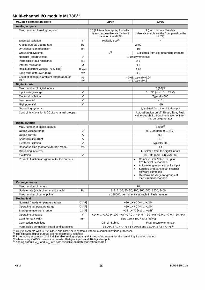
Multi-channel I/O module ML78B1)
ML78B + connection board AP78 AP75
Analog outputsMax. number of analog outputs 10 (2 filterable outputs, 1 of which
is also accessible via the frontpanel on the ML78)
2 (both outputs filterable1 also accessible via the front panel on the
ML78)
Electrical isolation V Typically 5002) −
Analog outputs update rate Hz 2400
D/A conversion resolution bit 16
Grounding systems 23) 1, isolated from dig. grounding systems
Nominal (rated) voltage V 10 asymmetrical
Permissible load resistance kΩ ≥ 5
Internal resistance Ω < 5
Residual carrier voltage (76.6 kHz) mVPP < 12
Long-term drift (over 48 h) mV < 3Effect of change in ambient temperature of10 K
%mV
< 0.08; typically 0.04< 3, typically 2
Digital inputsMax. number of digital inputs 8 (16)4)
Input voltage range V 0 ... 30 (nom. 0 ... 24 V)
Electrical isolation V Typically 500
Low potential V < 5
High potential V >10
Grounding systems 1, isolated from the digital output
Control functions for MGCplus channel groups Autocalibration on/off; Reset; Tare; Peakvalue clear/hold; Synchronisation of inter-
nal curve generator
Digital outputsMax. number of digital outputs 8 (16)4)
Output voltage range V 0 ... 30 (nom. 0 ... 24V)
Output current A 0.5
Short-circuit current A 1.5
Electrical isolation V Typically 500
Response time (not for “external” mode) ms < 4
Grounding systems 1, isolated from the digital inputs
Excitation V 18 ... 30 (nom. 24); external
Possible function assignment for the outputs • Combine Limit Value for up to120 MGCplus channels
• Acknowledgement signal for input• Settings by means of an external
software command• Overflow message for groups of
measurement channels
Curve generatorMax. number of curves 10
Update rate (each channel adjustable) Hz 1; 2; 5; 10; 20; 50; 100; 200; 600; 1200; 2400
Max. number of curve points ≤ 128000, permanently storable in flash memory
MechanicalNominal (rated) temperature range °C [°F] −20 ...+ 60 [−4 ... +140]
Operating temperature range °C [°F] −20 ...+ 60 [−4 ... +140]
Storage temperature range °C [°F] −25 ...+ 70 [−13 ... +158]
Operating voltages V +14.6 ... +17.0 (< 100 mA)/ −17.0 ... −14.6 (< 90 mA)/ −9.0 ... −7.0 (< 10 mA)
Card format / width mm Euro 160 x 100 / 20.3 (4divs)
Connection technique 25−pin Sub−D Plug-in screw terminals
Permissible connection board configurations 1 x AP78 / 1 x AP75 / 1 x AP78 and 1 x AP75 / 2 x AP755)
1) Only in systems with CP22, CP32 and CP42 or in systems without a communications processor.2) The filterable digital outputs are not electrically isolated!3) 1 grounding system for 2 digital filterable analog outputs and 1 grounding system for the remaining 8 analog outputs4) When using 2 AP75 connection boards: 16 digital inputs and 16 digital outputs5) Analog outputs VO1 and VO2 are both available on both connection boards
B0554-15.0 enHBM 40

Connection board for Multi−channel I/O module ML78B
AP75 AP78
AB22A/AB32 Display and Control PanelWidth 111.8 mm (22 divs)
Display AB22A
AB32
Backlit LCD display, resolution 192x64 pixels
Vacuum-fluorescent display (VFD), resolution 192x64 pixels
Key panel Keypad (alphanumeric), 4 function keys, cursor keys and dialog keys. All keys are touch-sensitive
Password There is a facility for protecting certain operating levels with a password
Dialog Menu languages: German/English/French/Spanish
Display formats 1, 3, 6 values; ty graph, xy graph; limit value status
Weight approx. 0.5kg
ABX22A Portable Display and Control UnitIlluminated display no
Front width mm 111.8 (22 divs)
Current consumption (8V) mA 20
Length of cable (6-wire) m 1.5
Receptacle type Binder coupler receptacle, in accordance with
DIN 45326, Series 723, 8-pin, No. 09-0171-15-08
AB22A AB32AB121)
MGCplus
1) With single-channel amplifiers ML01B/10B/30B/35B/38B/50B/55B/60B only.
B0554-17.0 en HBM41

CP22 Communication processorWidth mm 40.6 (8 divs)
Interfaces Potentialseparation
Connectiontechnique
Baud rate
RS-232-C No 9-pin D−subfemale connector
38.4 kBaud
USB2) (master/slave) No USB femaleconnector
12 MBaud (fast mode)
Ethernet Yes RJ45 10/100 MBaud
Data transfer rateEthernet (64 channels/4Byte-measured values/sampling rates 2400 Hz)
USB (24 channels/4Byte-measured values/sampling rates 2400 Hz)
Measured values/s
Measured values/s
153 600
57 600
Nominal (rated) temperature range °C [°F] −20 ... +65 [−4 ... +149]
Operating temperature range °C [°F] −20 ... +65 [−4 ... +149]
Storage temperature range °C [°F] −25 ... +70 [−13 ... +158]
Weight kg approx. 0.6
I/O contactsPotential separation V DC 500
Connection technique 1 x In, 1 x Out, 24 V, GND Screw terminals (line less than 30 meters long)
Input voltage level LOW V 0 ... 5
Input voltage range HIGH V 10 ... 24
Input current, typically, high level = 24 V mA 12
Input current, typically, high level = 10 V mA 3
Output level active high at 0 A Level supply minus 0.7 V
Output level active high at 0.5 A Level supply minus 3 V
Power supply (external) V 24 (11 V ... 30 V)
Output current, max. A 0.5
Short-circuit current, typically A 0.8
Short-circuit period unlimited2) Cable length 5 m; Cable extensions are not permissible.
CP42 Communication processorWidth mm 60,9 (12 divs)
Interfaces Potential se-paration
Connectiontechnique
Baud rate
RS-232-C typ. 500V 9-pin D−subfemale connector
115.2 kBaud
USB3) (master/slave) No USB femaleconnector
12 MBaud (fast-mode)
Ethernet typ. 500V RJ45 100 MBaud
Data transfer rateEthernet (128 channels/sampling rate 2400 Hz)USB (32 channels/sampling rate 2400 Hz)PC card harddisk
(approx. 109 channels/sampling rate 2400 Hz)(128 channels/sampling rate 2400 Hz)
Measured values/sMeasured values/s
Measured values/sMeasured values/s
307 200 (4−byte format)76 800 (4−byte format)
262144 (4−byte format)307200 (2−byte format)
Nominal (rated) temperature range °C [°F] −10 ... +55 [+14 ... +131]
Operating temperature range °C [°F] −10 ... +55 [+14 ... +131]
Storage temperature range °C [°F] −25 ... +70[−13 ... +158]
Weight kg approx. 0.6
Extension (optional) PC card harddisk, up to 5Gbyte, ATA standard
I/O contactsPotential separation V DC 500
Connection technique 2 x In, 2 x Out, 24 V, GND Screw terminals (line less than 30 meters long)
Input voltage level LOW V 0 ... 5
Input voltage range HIGH V 10 ... 24
Input current, typically, high level = 24 V mA 12
Input current, typically, high level = 10 V mA 3
Output level active high at 0 A Level supply minus 0.7 V
Output level active high at 0.5 A Level supply minus 3 V3) Cable length 5 m; Cable extensions are not permissible.
B0554-15.0 enHBM 42

Power supply (external) V 24 (11 V ... 30 V)
Output current, max. A 0.5
Short-circuit current, typically A 0.8
Short-circuit period unlimited
RM001 Relay moduleInput voltage V 0 / 5
Resistance kΩ 12
Response time ms maximum 5
Release time ms maximum 25
Relay breaking capacity max. voltagemax currentmax. power
VA
VA
42130
Operating voltage V +8; −8
Power consumption mA 34
Relay-module life mechanical
electrical (at nominal (rated) load)
Switchingcycles
Switchingcycles
50 x 106
100 x 103
Weight, approx kg 0.1
EM001 Output stage module4)
Input
Input voltage V −10 ... +10
Input resistance kΩ 12.5
Output
Impressed voltage V −10 ... +10
Impressed current mA 20 / 4 ... 20
Load resistance Ω maximum 500 minimum 500
Measuring frequency range kHz 10
Operating voltage V +16; −16
Power consumption mA 35
Weight, approx kg 0.14) The EM001 output stage module can only be used with connection boards without transducer identification.
B0554-17.0 en HBM43

Hottinger Baldwin Messtechnik GmbH
Im Tiefen See 45, D-64293 Darmstadt, GermanyTel.: +49 6151 8030; Fax: +49 6151 803 9100E−mail: [email protected] www.hbm.com
Modifications reserved. All details describe our products in general form only. Theyare not to be understood as express warranty and do notconstitute any liability whatsoever.
B0554-17.0 en