Embed Size (px)
Citation preview
MEASUREMENTS OF PRESSURE DlSTRlBUTlONS AND FORCE COEFFlClENTS I N A SQUEEZE FILM DAMPER -
PART I : FULLY OPEN ENDED CONFIGURATION
S.Y. Jung, L.A. San Andres, and J.M. Vance Department o f Mechanical Engineering
Texas A&M Un ive rs i t y College Sta t ion, Texas 77843-3123, U.S.A.
Experimental measurements of pressure distributions and force coefficients obtained from a squeeze film damper test rig executing a circular centered orbit are presented. The test rig has been designed to study the effect of fluid inertia on the pressure field and dynamic force response on a damper configuration with a relatively large clearance. Past measurements of the squeeze fdm damper force characteristics have been carried out at squeeze film Fkynolds numbers not exceeding a value equal to 10. In the present paper, following contemporary applications, operations at Reynolds numbers up to fifty axe tested for CCO1s with an orbit radius=0.8 (Re 5 10 at E = 0.5). The results obtained ftom a fully open ended damper are presented in detail. The effects of fluid inertia, cavitation and the open end geometry on the pressure distributions and force coefficients are discussed.
NOMENCLATURE
=SFD radial clearance =pw L R3 /C damping coefficient conversion factor =pL R3 /C inertia coefficient conversion factor =pwR3 L/C2 force conversion factor =pw R2 /C2 pressure conversion fact or =C, . Re = pw2 R2 pressure conversion coefficient =dimensionless direct damping coefficients =- f t / e , normalized by pR3 L /C3 =damper journal diameter =dimensionless direct inertia coefficients = f , / e , normalized by pR3 L/wC3 =dimensionless radial and tang. fdm forces normalized by Cf = f pcos Ode, f psin Ode, respectively =damper journal length
79 PRECEDlNG PAGE B U N K NUT FILMED
https://ntrs.nasa.gov/search.jsp?R=19920005134 2018-05-30T00:13:17+00:00Z
=dimensionless pressure normalized by Cp =damper journal radius = w e 2 /u modified Reynolds number =axial coordinate =dimensionless orbit radius =circumferential coordinate =absolute viscosity =kinematic viscosity =density =90° +tan-' fT/ft , phase angle =frequency of damper journal center motion
INTRODUCTION
Squeeze film dampers have been successfully used to control vibration in turbomachinery. Numerous studies both theoretically and experimentally have been presented for squeeze film dampers. However, due to the fluid film pressure distortion factors such as oil grooves, end seals, cavitation, and fluid inertia, experimental results are often not consistent with predictions.
In the 1 9 7 0 ' ~ ~ many researchers [I-51 measured the hydrodynamic pressure field and damping; coefficients from a number of squeeze! flm'damper test rigs and compared themuto the1 conventional~solutionof Reynolds equation. Correlation be- tween experimental measurements and theoretical predictions was qualitatively reasonable but quantitatively poor in most cases.
In the 1980's, the effect of fluid inertia on the pressure distribution and dynamic force response of squeeze film dampers was shown to be of great impor- tance [6-SO]. Experiment a1 measurements [ll-151 demonstrated the significant effect of fluid inertia through both the direct measurements of film pressure and forces and the indirect measurements from the dynamic response of rotor sys tems.
Most measurements of a squeeze film damper have been carried out at squeeze film Reynolds numbers not exceeding 10. However, in contemporary practical applications, the squeeze Reynolds number ranges from 10 to 50. Thus the need exists for experimental measurements to cover the maximum practical range of Reynolds numbers up to Re=50.
The objective of this paper is to present an experimental study on the effect of fluid inertia and cavitation on the pressure distributions and force coefficients. Two types of squeeze film dampers with its journal executing a circular centered orbit are tested: fally open ended and partially sealed configuratiocs. The results obtained from a fully open ended test rig and a partially sealed test rig are presented in part I and 11, respectively. The range of Reynolds number tested is between 2 and 50. Measured fluid film pressure profiles and force coefficients are compared with existing theoretical predictions.
EXPERIMENTAL FACILITY AND PROCEDURE
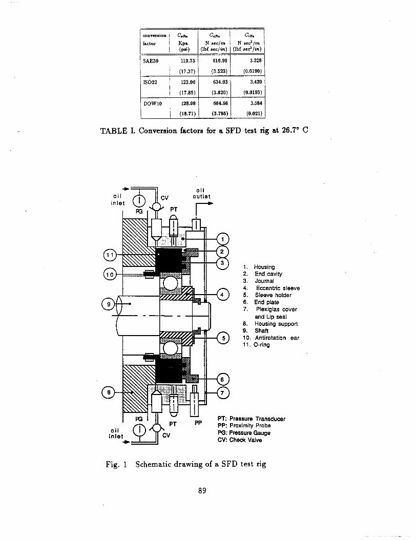
Description of the SFD Test Apparatus The schematic drawing in Figure 1 shows the structure of the squeeze film
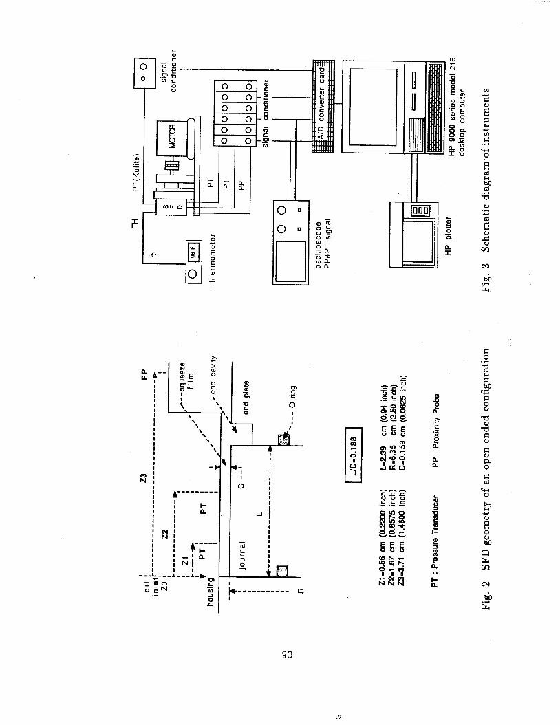
damper (SFD) test rig. The damper journal with an outer diameter of 12.7 cm (5 inch) and a length of 2.4 cm (0.94 inch) is mounted with a press fit on the outer race of a ball bearing. An O-ring seal is installed at the left end face of the damper journal and provides afilll proof of a no leak seal. The LID ratio is equal to 0.188 and simulates a short bearing configuration typical of a real engine damper application. The clearance is 0.159 cm (0.0625 inch). The large clearance produces large values of Reynolds number at low speeds so that significant effects of fluid inertia are produced.
The end plate of the journal secures the right end face of the journal. The outer diameter of the end plate is used to measure the orbital motion of the journal during operation. The end plate not only preserves alignment of the housing and journal, but dso provides a circumferential end cavity. The width and depth of the end cavity are 0.44 cm (11164 inch) and 0.40 cm (0.156 inch), respectively. The end cavity is utilized with ancillary hardware to produce several different configurations such as short, long, and finite length bearings using different types of end seals.
The ball bearing supporting the damper journal is mounted on a replaceable eccentric sleeve that lockes to the shaft with a special retainer. The shaft is driven by a constant speed electric motor at 1770 rpm (29.5 Hz). The motor end of the shaft is supported by two more ball bearings (not shown in Figure I ) mounted on stiff supports to minimize lateral movement of the shaft and the damper journal. The shaft is connected to the motor by a flexible coupling to prevent axial loads on the journal.
The bearing housing has numerous holes for oil inlet and outlet, pressure transducers, and proximity probes. Figure 2 shows a sketch of the squeeze film land. At the axial location ZO, two 0.24 cm (3132 inch) diameter holes located at the circumferential locations 270" (top) and 90" (bottom) serve as the oil inlets to the damper annulus. The two oil inlet holes have check valves to prevent flow reversals from the squeeze film region. Dial pressure gauges are connected to the inlet lines in order to measure the oil supply pressure.
At two different axial locations, Z1=0.56 cm (0.22 inch) and Z2=1.67 cm (0.66 inch), a total of 16 holes are distributed in the circumferential direction for installation of pressure transducers (PT). These holes may be used to directly measure the temperature of the fluid film inside the damper using a dummy pressure transducer with a small hole plugged with a thermocouple wire. The unused holes in the housing are plugged with dummy pressure transducers to prevent lubricant leakage.
At the axial location Z3=3.72 cm (1.46 inch), a single 0.64 cm (114 inch)
diameter oil outlet is located at the circumferential location 270" (top) of the housing in order to get a completely submerged arrangement. Oil is never pumped out of the damper oil outlet, but flows naturally. The bearing housing has a hole for proximity probes (PP) at the axial location 23 and circumferential locations 180" (left).
The Plexiglas cover with a lip seal covers the end of the bearing housing and insures a completely submerged arrangement and sufficient oil in the squeeze film region. The completely submerged arrangement prevents air entrance into the squeeze film region.
Experimental Procedure
Figure 3 shows the instrumentation arrangement for measurement of the fluid flrn pressure and real time calculation of the flrn force coefficients at a specified axial location of the SFD test rig.
In the case of a circular centered SFD, since the time variations in cir- cumferential pressure measured at any location on the damper annulus should be identical for any one cycle of the journal, the fluid film pressure profile for a centered orbit motion can be measured with only one pressure transducer. Furthermore, since the orbit motion is centered, only one proximity probe is required to determine the dynamic eccentricity ratio.
Therefore, one proximity probe was installed at the axial location 2 3 and the circumferential location 180" on the outside diameter of the end plate. The proximity probe measures the journal displacement, from which the variation of film gap in the squeeze film region can be determined. Two dynamic pressure transducers were installed at two different axial locations 21 and 22 and ciztumfe-~ntial location 180" to study the axial pressure variation caused by end leakage. The variation of the pressure distribution in both the axial and the circumferential directions are monitored with two dynamic pressure transducers. The piezo-electric pressure transducers used can measure only the dynamic variation of film pressure. Thus, a strain-gage pressure transducer to measure absolute pressure was installed at the axial location Z1 and the circumferential location 330". Absolute value of pressure obtained from the pressure transducer gives information about the cavitation pressure.
A thermocouple type T was embedded with an epoxy resin into a small hole drilled into a dummy pressure transducer at the axial location Z1 and the circumferential location 210". The thermocouple is flush with the wall of the bearing housing so that the temperature of the oil flrn in the squeeze flrn region is directly measured. The value of temperature was input for calculation of the viscosity of the oil and the corresponding Reynolds number. The increase of the temperature of the oil is mainly due to shear friction of the oil and heat conduction from the ball bearing supporting the damper journal.
The squeeze film Reynolds number Re = uC2/v physically represents the ratio of the fluid inertia force to the viscous force. Observation of the variation
in Reynolds number is very important to study the effects of fluid inertia on the pressure distribution and force coefficients. Since the whirling frequency w of the journal and the radial clearance C of the SFD test rig are fixed values, the oil viscosity is the only factor that can be varied to obtain a change in the Reynolds number.
Oil viscosity was measured for a range:ofkemperatures prior to experimental tests using a Synchro-Lectric viscometer (LVF model). Oil viscosity formulae were obtained in terms of temperature using a mathematical relation suggested in the ASTM D-341. Three kinds of oils have been used in the experimental tests; SAE30 oil (engine oil), IS022 oil (turbine oil), and DOWlO oil (silicone oil). The range of temperature measured was between 27" C(80° F ) and 49" C(120°F). The corresponding Reynolds numbers range from Re=2 to Re=7 for SAE3O oil, Re=17 to Re=35 for IS022 oil, and Re=42 to Re=48 for DOWlO oil.
Oil supply pressures were about 68.75 KPa (10 Psig) which allowed a flow rate equal to 200 rnl per min. for SAE30 oil, and about 13.8-20.6 KPa (2-3 Psig) for lower viscosity oils. Higher oil supply pressures can not be applied to the damper because of deformation of the plexiglas cover. Also, higher oil supply pressures produce a notable distortion of the fluid film pressure field, because the two small oil inlets directly supply oil into the squeeze film region (there is no circumferential oil inlet groove). The oil inlet groove is often employed in squeeze film dampers to prevent distortion of the pressure field due to inlet holes. Previous experimental measurements have shown that an oil groove has a large effect on the pressure distortion [11,13]. Since experiments with a circular centered orbit should yield pressure distributions independent of the location of the pressure transducer, it is very important to get rid of potential distortion factors for better comparison between experiment and analysis.
In the experimental measurement reported here, 60 data points per cycle per pressure transducer and proximity probe were taken. Each measurement consisted typically of 3 cycles. The force coefficients are the averaged values obtained from integration of these 3 cycles of the measured pressure profiles.
EXPERIMENTAL RESULTS AND DISCUSSIONS
Experimental tests have been performed on the squeeze film damper (SFD) test rig to measure dynamic pressure distributions and force coefficients with orbit radii equal to 0.5 and 0.8. Table I shows the conversion factors for proper dimensional values of pressure and force coefficients for the three kinds of oils used in the experimental work. These factors are used to get the corresponding dimensional values of the measured dimensionless pressure and force coefficients. To predict the measured pressure distributions and film force coefficients, a modified short bearing solution [I61 is used. The analytical model used included the effects of finite length and fluid inertia.
Pressure Distributions
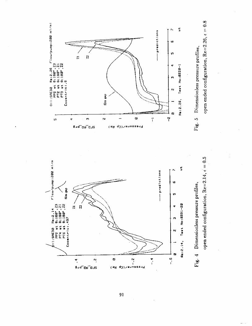
Figures 4 and 5 show comparisons between the measured and predicted pressure profiles for orbit radius equal to 0.5 and 0.8, respectively. The viscous lubrication solution produces antisymmetric pressure profiles with respect to the maximum film thickness (wt* = n), while the additional pressure due to the fluid inertia is symmetric with respect to wt* = x [14]. Referring to the combined pressure profile including the additional inertial pressure, the main effects of fluid inertia are that the positive dynamic peak pressure is smaller than the negative dynamic peak pressure, and the dynamic pressure has a negative value at the minimum film thickness (wt* = 0) while it has a positive value at the maximum film thickness (wt* = n).
The pressure profile with a orbit radius E = 0.8 corresponds to a cavitated film as shown in Figure 5. The absolute levels of pressure measured are close to zero absolute and thus, these indicate vapor cavitation in the lubricant film.
According to conventional lubrication theory, negative dynamic pressure is produced in the diverging section of bearing while positive dynamic pressure is produced in the converging section of bearing. Contrarily, as shown in Figure 5, negative pressure exists in the converging section of the SFD. It has been generally assumed that the positive pressure profile is unaffected by cavitation, but it is presumed here that vapor cavitation influences the positive pressure region.
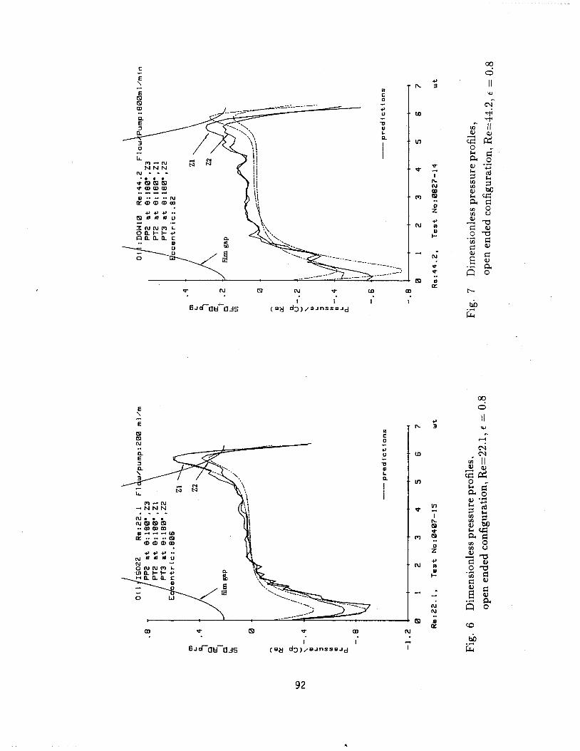
For reduced oil viscosities, the extent of the vapor cavitation becomes smaller. For E = 0.8, the measurements showed that the cavitation completely disappeared at Re=22.1. Figure 6 shows the measured pressure which corre- sponded to IS022 oil.
An important characteristic of the open ended configuration is the large pressure drop in the axial direction due to the substantial flow in the axial direction. In Figures 5 and 6, the amount of pressure drop measured at axial location 22 is about 40% of the peak positive pressure at axial location Z1. The modified short bearing solution [16] predicts 46% of pressure drop between the two axial locations. The measurements confirm that the modified short bearing model can adequately describe the axial pressure drop in a parabolic form. However, the predicted pressure profile at the axial location 22 is poor in the negative dynamic pressure region. The peak negative pressure drop measured at the axial location 22 is about 20% of that at Z1 a.t large Reynolds numbers (Re>20). The parabolic variation of the axial pressure predicted from the modified short bearing solution is therefore not valid in the negative pressure region where the Reynolds number is large. Since the film is completely submerged, the negative pressure produced in the diverging section creates reversed flow in the axial direction. Thus, a Bernoulli effect is likely to be significant which violates the boundary condition p=O at the end of the damper.
Figure 7 shows dynamic pressure waves obtained at Reynolds number equal to 44.2. In these figures the distortion of t,he antisymmetric shape of the viscous
pressure profile is magnified, and the pressure profile is dominated by the effects of fluid inertia. The negative peak pressure is about three times the positive peak pressure in magnitude. The analytical predictions deteriorate for these large Reynolds numbers.
During the pressure measurements at small Reynolds number with ~=0.5 and at large Reynolds number with ~ = . 8 , the pressure signals on an oscilloscope were fluctuating, as seen on the Figures 4 and 7. Thus the fluid flows at these large Reynolds numbers may not be laminar and the Bernoulli effects may become more significant at low viscosities. Also there is a noise interference at low levells of pressure. For an orbit radius E = 0.5, it was not possible to measure the pressure distribution at large Reynolds number (Re>lO) because of the large ratio of noise to measured values.
During operation of the SFD test rig no bubbles came out of the squeeze f lm region, but many minute bubbles simultaneously appeared in the oil a few seconds after stopping the test rig and oil supply pump. It is presumed that the air dissolved in the oil came out of solution when the external oil supply pressure was removed.
Force Coefficients Experimental fluid film forces and force coefficients are determined by
numerical integration of the measured pressure waves around the damper journal surface. For the analytical predictions, a full film assumption (27r flm) with orbit radii E = 0.5 and 0.82 are used. Since the pressure profiles for E = 0.8 are cavitated at small Reynolds numbers (Re5 lo), corresponding predictions are excluded here. The force coefficients are calculated locally and corresponded to a unit axial width of the damper at the specific axial locations.
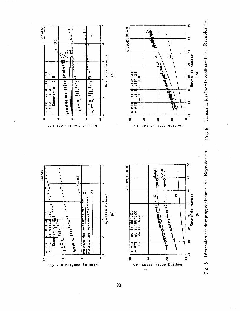
Figures 8 show the local damping coefficients Ctt computed from the measured pressure profiles. Since cavitation is present in the pressure profiles of E = 0.8 and for Reynolds numbers less than 10, the measured damping coefficients must be regarded as equivalent damping coefficients, i.e. equal to (Ctt - DtT). But at Reynolds numbers larger than 15, the damping coefficients are purely direct coefficients because of no cavitation in the measured pressure profiles.
Generally, the predictions for the local damping coefficients using the modified short bearing solution [16] compare favorably with measurements at the axial location Z1. However, the predicted coefficients are poor at the axial location 22. The main reason is that the parabolic axial pressure profile obtained from the short bearing theory does not properly predict the axial pressure drop in the negative region when both Reynolds number and orbit radius are large. A level of the dimensional values of damping achieved in the test rig can be easily obtained if the measured damping coefficients Ctt are multiplied by CdRe/Re (CdRe is given Table I).
Figures 9 show the local inertia coefficients D,, calculated from the mea-
sured pressure data. For E = 0.8 at Reynolds number below Re=lO, the inertia coefficients are to be regarded as an equivalent inertia coefficient, i.e. equal to (D,, - CVt) due to the observed cavitation in the measured pressure profiles. Since the region of cavitation increases as the Reynolds number decreases, the equivalent inertia coefficients correspond mainly to the cross coupled damping coefficients at small Reynolds number with ~=0.8. The dimensional values of inertia coefficients can be obtained by multiplication of CiR,/Re in Table I.
For a orbit radius E = 0.8 at Reynolds number less than Re=lO, the inertia coefficients at both the axial location Z1 and 22 are negative, showing the cross coupled damping force is dominant. (Cross coupled damping has been described as dynamic stiffness [17,18]). For Reynolds number larger than 15, the inertia coefficients become positive, which means that fluid inertia overcomes the effect of the cross coupled damping and acts as an added mass on the journal. The prediction of the local inertia coefficients are poor at the axial location 22 near the end of the damper journal as in the case of the damping coefficient prediction. Once again, the parabolic axial pressure profile can not be used in the negative pressure region.
Damping coefficients are seen to be large at small Reynolds number and indicate a dominance of viscous effects. As the Reynolds number increases, the inertia coefficients eventually approach the same level of the damping coefficients as shown in Figures 8 and 9, and show that the fluid inertia forces become dominant
San Andres [9,10] determined fluid film forces and force coefficients based on the assumption that fluid inertia do not affect the velocity profiles or flow rates. The important results were
1) The dimensionless damping coefficient Ctt is purely viscous and not affected greatly by fluid inertia.
2) The fluid inertia force increases linearly with Reynolds number so that the dimensionless inertia coefficient D,,/Re has a constant value for small to moderate Reynolds number.
However, since the above assumption is valid for very small Reynolds number (Re<l), as the fluid inertia forces approach the same order of magnitude as viscous forces for large Reynolds number (ReZlO), the effect of fluid inertia forces on the velocity profile then becomes significant and needs to be considered. When the effect of the fluid inertia forces on the velocity profiles or flow rates is included in the analysis, the dimensionless damping coefficient Ctt and inertia coefficient D,,/Re, both become strongly dependent on the Reynolds number 1161. Experimental evidence supporting these results is shown in Figures 8 and 9.
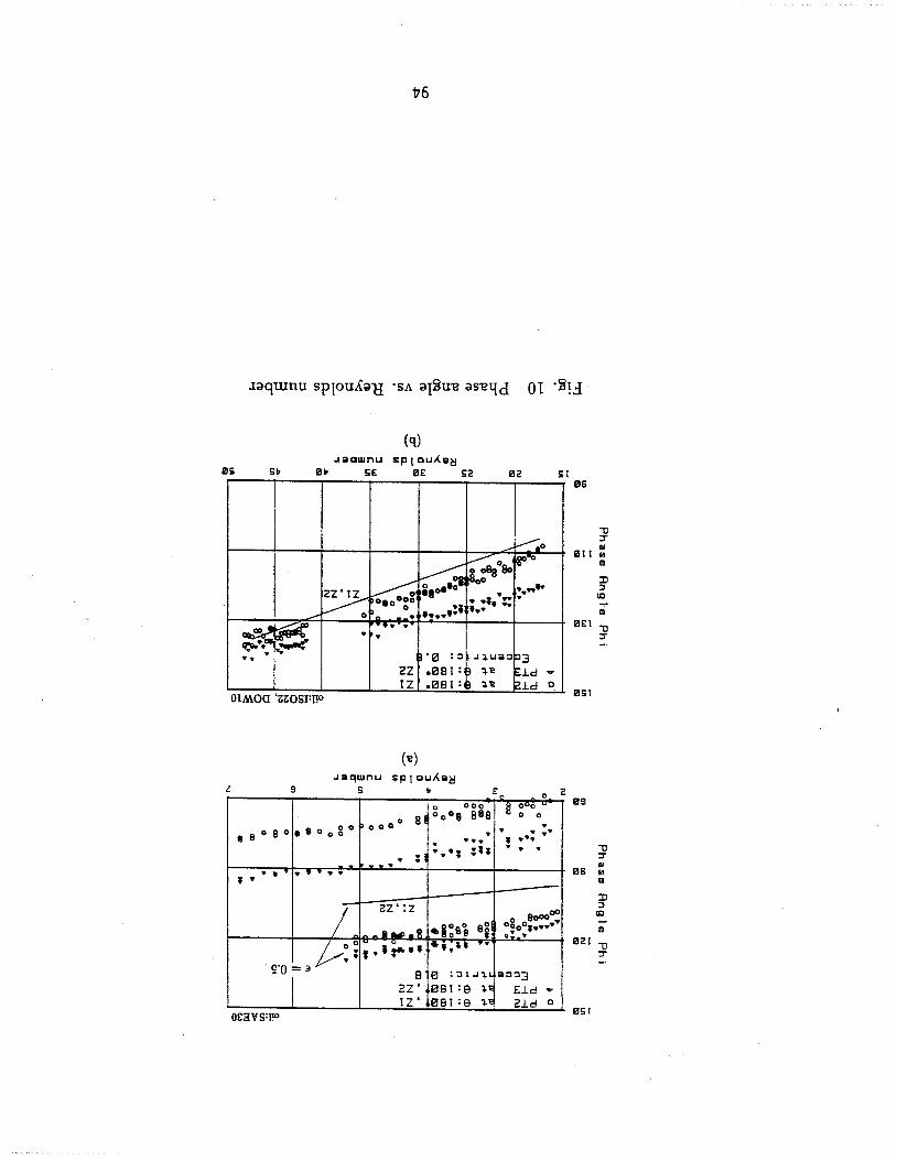
Figure 10 shows the force phase angle calculated from the force coefficients given in Figures 8 and 9. It is important to notice how the point of application of the total fluid film force relative to the position of the maximum film thickness changes as the Reynolds number increases. If the viscous film force is dominant,
the radial film force is very small compared to the tangential film force and the phase angle approaches q5 = 90"; while if the inertial f lm force is dominant, the radial f lm force is very large (outward) compared to the tangential film force and the phase angle q5 approaches q5 = 180". Thus, phase angles above 90" indicate a film radial force component due to fluid inertia. Predictions of phase angle obtained from the modified short bearing solution agree well with the measurements.
CONCLUSIONS
Experimental measurements have been performed on an open ended squeeze film damper executing circular centered orbits. Dynamic pressure measurements were obtained for two orbit radii, c = 0.5 and 0.8. Corresponding force coeffi- cients were calculated by numerical integration of the measured pressure profiles From the experimental measurements presented, the following conclusions can be described:
I) The parabolic axial pressure profile obtained from the modified short bearing solution can adequately predict the axial pressure drop in the positive dynamic pressure region, but not in the negative dynamic pressure region. These effects are more pronounced at large Reynolds numbers.
2) Cavitation observed in the submerged damper corresponds to vapor cavitation. The vapor cavitation influences not only the negative pressure field in the diverging region of a damper, but also the positive pressure field in the converging region of the damper.
3) Inertia coefficients D,,/Re (radial film force) become comparable to damping coefficients Ctt (tangential film force) as Reynolds number increases. Both the measured inertia and damping coefficients increase with increasing Reynolds numbers.
The experimental results obtained from a partially sealed configuration are presented in Part 11.
REFERENCES
[I] Thomsen K. K. and Andersen H., "Experimental Investigation of a Simple Squeeze Film Damper", ASME J. of Eng. for Industry, May 1974, pp.427- 430
[2] Vance J. M. and Kirton A. J., "Experimental Measurement of the Dynamic Force Response of a Squeeze Film Bearing Damper", ASME J. of Eng. for Industry , Nov. 1975, pp. 1282-1290
[3] Tonnesen J.,"Experimental Parametric Study of a Squeeze Film Bearing", ASME J. of Lubrication Technology, April 1976, pp. 206-213
[4] Feder E., Bansal P. N., and Blanco A.,"Investigation of Squeeze Film ' Damper Forces Produced by Circular Centered Orbits", ASME J. of Eng. for Power, Vol. 100, Jan. 1978, pp. 15-21
Miyachi T., Hoshiya S., Sofue Y., Matsuki M., and Torisaki T., "Oil Squeeze Film Dampers for Reducing Vibration of Aircraft Gas Turbine Engines", ASME paper no. $9-GT-133, 1979 Szeri, A. Z., Raimondi, A. A., and Giron-Duarte, A., "Linear Force Coefficients for Squeeze-Film Dampers", J. of Lubrication Technology , Vol. 105, July 1983, pp. 326-334. Tichy, J. A., "The Effect of Fluid Inertia in Squeeze Film Damper Bearings; A Heuristic and Physical Description", ASME paper no. 83-GT-177. Tichy, J. A., "A Study of the Effect of Fluid Inertia and End Leakage in the Finite Squeeze Film Damper", ASME paper no. 86-Trib-62, 1986 San Andres, L., and Vance, J. M, "Effects of Fluid Inertia and Turbulence on the Force Coefficients for Squeeze Film Dampers", ASME paper no. 85-GT-191, 1985. San Andres, L., and Vance, J. M., " Effects of Fluid Inertia on Finite Length Squeeze Film Dampers", ASLE Trans. Vol. 30, 3, 1987, pp. 384-393 Tecza J. A., Giordano J. C., Zorzi E. S., and Drake S. K.,"Squeeze Film Damper Technology: Part 2 - Experimental Verification Using a Controlled Orbit Test Rig", ASME paper no. 83-GT-248, 1983 Tichy J. A.,"Measurements of Squeeze Film Bearing Forces to Demonstrate the Effect of Fluid Inertia", ASME paper no. 84-GT-11, 1984 Ramli M. D., Roberts J. B., and Ellis J. "Determination of Squeeze Film Dynamic Coefficients from Experimental Transient Data", ASME paper no. 86-Trib-17, 1986 San Andres L. A. and Vance J. M.,"Experimental Measurement of the Dy- namic Pressure Distribution in a Squeeze Fiim Bearing Damper Executing Circular Centered Orbits", ASLE Trans., Vol. 30, 3, July 1987, pp. 373-383 Burrows C. R., Kucuk N. C., and Sahinkaya M. N., "Estimation of Squeeze Film Bearing Inertia, Damping and Stiffness Coefficients", ASME Rotating Machinery Dynamics, Vol. 1, Sep. 1987, pp. 109-114 S. Y. Jung, "Effects of Fluid Inertia and Cavitation on the Force Coefficients of a Squeeze Film Damper", Ph.D. Dissertation, Dept. of Mechanical Eng., Texas A&M University, May 1990 Rabinowitz, M. D., and Hahn, E. J., "Optimal Design of Squeeze Film Supports for Flexible Rotors", J. of Eng. for Power, July 1983, pp. 487- 494 .- Gunter, E. J., Barrett, L. E., and Allaire, P. E., "Design of Nonlinear Squeeze-Film Dampers for Aircraft Engines", J. of Lubrication Technology, Jan. 1977, pp. 57-64.
factor Kpa I (poi)
SAE3O ' 119.75 i
TABLE I. Conversion factors for a SFD test rig at 26.7' C
i (17.85) 1 (3.620)
DOWlO 1 128.98 1 664.56
II ." oil outlet
N sec/m (lbf sec/in)
616.99
(0.0195)
3.584
Housing End cavity Journal
N sec2/m (Ibf se2 / in)
3.328
4. Eccentric sleeve 5. Sleeve holder 6. End plate 7. Plexiglas cover
and Lip seal 8. Housing support - . . 9. Shaft 10. Antirotation ear 11. O-ring
PT: Pressure Transducer PP PP: Proximity Probe
o i l in le t
PO: Pressure Gauge CV: Check Valve
Fig. 1 Schematic drawing of a SFD test rig
I o
il '
23
P
P
7
P-- s
quee
ze
P
film
I
PT
I I
0
I I
I I
I I
I
/end
ca
vity
I I
P '---
0 r
ing
-i-
1 I I
21-0
.56
cm (
0.22
00 i
nch)
L-
2.39
cm
(0.
94 i
nch)
22
11.6
7 cm
(0.
6575
inc
h)
R-6
.35
cm (
2.50
inc
h)
2313
.71
cm (
1.46
00 i
nch)
C
-0.1
59
cm (
0.06
25 i
nch)
A r
c --
t r
r
jou
rnal
en
d pl
ate
I
'-4
sign
al
cond
ition
er
osci
llosc
ope
PP
BP
T s
igna
l
ther
mom
eter
PT
: P
ress
ure
Tran
sduc
er
PP
: P
roxi
mity
Pro
be
nr
plot
ter
HP
900
0 se
ries
mod
el 2
16
1
I I
sign
al
cond
ition
er
PT
desk
top
com
pute
r
PT
PP
Fig
. 2
SF
D g
eom
etry
of
an o
pen
ende
d co
nfig
urat
ion
Fig
. 3
Sch
emat
ic d
iagr
am o
f in
stru
men
ts
00
00
00
00
00
00
Ra
:2.1
4.
Te
st
No
:03
31
-20
w
t
Fig
. 4
Dim
ensi
onle
ss p
ress
ure
prof
iles
,
open
end
ed c
onfi
gura
tion
, Re=
2.14
, E =
0.5
ons
Re
:2.2
6,
Te
rt
No
:02
20
-1
w t
Fig
. 5
Dim
ensi
onle
ss p
ress
ure
prof
iles
,
open
end
ed c
onfi
gura
tion
, R
e=2.
26,
c =
0.8
hil G
hil iz
El- m 0 C X