Embed Size (px)
Citation preview
Measurements of a three-dimensional flow in a cube by means of an ultrasound array Doppler velocimeter (UADV)
Vladimir Galindo1, Richard Nauber2, Sven Franke1, Dirk Räbiger1, Lars Büttner2, Norman Thieme2, Hannes Beyer2, Jürgen Czarske2, and Sven Eckert1 1 Helmholtz – Zentrum Dresden – Rossendorf, Dresden, Germany
2 Technische Universität Dresden, Germany
Velocity measurements were carried out in a cube filled with the liquid metal GaInSn using a dual plane, two-component ultrasound array Doppler velocimeter. It provides flow instrumentation at frames rate of typ. 11 Hz over long measurement durations (>1h) using an FPGA based signal processing, which enables capturing transient flow phenomena with nondeterministic onsets. The liquid metal was suddenly exposed to an azimuthal body force generated by a rotating magnetic field (RMF). The measurements show a similar flow structure compared to the case of the RMF-driven flow in a cylindrical container, in particular the so-called initial adjustment phase followed by an inertial phase which is dominated by inertial oscillations of the secondary flow.
The interest was especially focused on the onset of unsteady flow regimes. The transition from the steady double vortex structure of the secondary flow to an oscillating regime was detected at a magnetic Taylor number of Ta >
1.3×10⁵. A detailed analysis of the flow structure was done by means of the Proper Orthogonal Decomposition
(POD). Corresponding numerical simulations were performed showing an excellent agreement with the experimental data.
Keywords: Rotating magnetic field driven flow, Ultrasound velocity measurement, Spin-up, OpenFOAM, Proper orthogonal decomposition”
1. Introduction
In the last years a broad study about the flow in closed
circular cylindrical container under the action of a
rotating magnetic field was performed, paying special
attention to the transition from a steady to a time-
dependent flow regime [1]. The authors tried to find a
critical non-dimensional magnetic Taylor number Ta (cf.
Eq. 3) for the onset of the instabilities using different
direct numerical simulation methods. Most recently,
Grants and Gerbeth [2] conclude that the rotating-magnetic field driven flow in a circular cylinder becomes
unstable first to non-axisymmetric, azimuthally periodic
perturbations at diameter-to-height aspect ratios AR=D/H between 0,5 and 2. In this paper we present an
experimental and numerical study of the flow in a closed
cubic container driven by a rotating magnetic field. We
focused our interest in the transient behavior of the flow
and the characterization of the transition from a steady
state below the critical magnetic Taylor number (Ta <
Tacr) to oscillatory states and then, for a considerable
high Ta, to a completely unsteady state.
2. Experimental setup
The experimental setup consists of the eutectic metal
alloy GaInSn, which is liquid at room temperature,
enclosed in a cubic container with an edge length of 2L =
67,5 mm. The container is centered in the MULTIMAG
(MULTI purpose MAGnetic field) facility, which is
capable of generating different types of magnetic fields
with varying strength and frequency [3].
In the current study the investigations were focused on
the spin-up process, this means that the experiments were
started with the fluid being at rest. The liquid metal
(GaInSn) was suddenly exposed to an azimuthal body
force generated by a rotating magnetic field (RMF) with
a frequency of 50 Hz. Due to the electromagnetic force
action and the presence of walls, a vortex develops in the
horizontal plane (primary flow) as well as a secondary
flow in the meridional plane. Both planes are
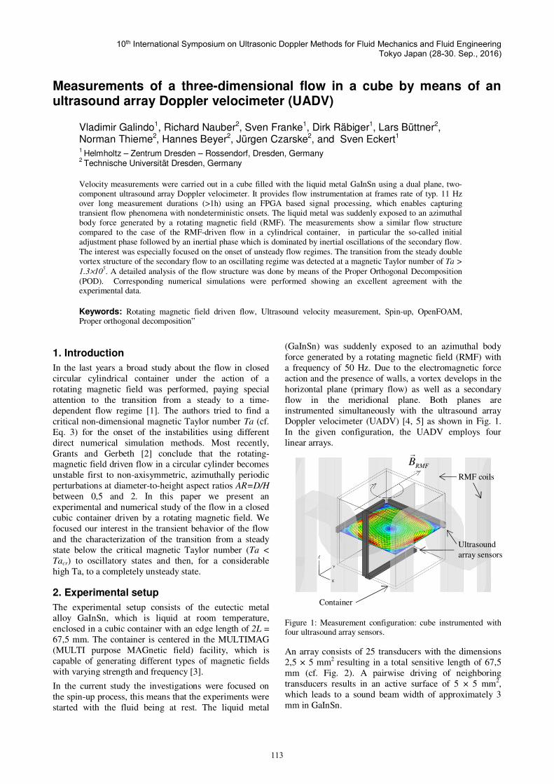
instrumented simultaneously with the ultrasound array Doppler velocimeter (UADV) [4, 5] as shown in Fig. 1.
In the given configuration, the UADV employs four
linear arrays.
Figure 1: Measurement configuration: cube instrumented with four ultrasound array sensors.
An array consists of 25 transducers with the dimensions
2,5 × 5 mm2 resulting in a total sensitive length of 67,5
mm (cf. Fig. 2). A pairwise driving of neighboring
transducers results in an active surface of 5 × 5 mm2,
which leads to a sound beam width of approximately 3
mm in GaInSn.
RMF coils
Ultrasound
array sensors
Container
RMFBr
10th International Symposium on Ultrasonic Doppler Methods for Fluid Mechanics and Fluid Engineering Tokyo Japan (28-30. Sep., 2016)
113
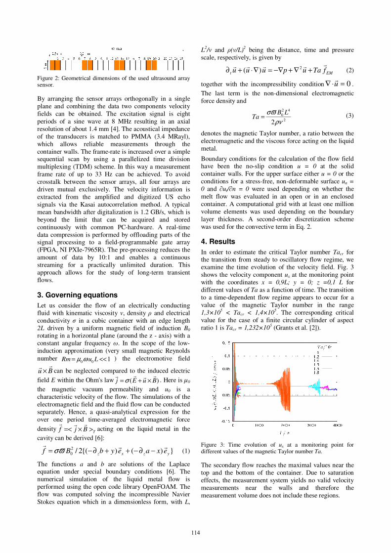
Figure 2: Geometrical dimensions of the used ultrasound array sensor.
By arranging the sensor arrays orthogonally in a single
plane and combining the data two components velocity
fields can be obtained. The excitation signal is eight
periods of a sine wave at 8 MHz resulting in an axial
resolution of about 1.4 mm [4]. The acoustical impedance
of the transducers is matched to PMMA (3.4 MRayl),
which allows reliable measurements through the
container walls. The frame-rate is increased over a simple sequential scan by using a parallelized time division
multiplexing (TDM) scheme. In this way a measurement
frame rate of up to 33 Hz can be achieved. To avoid
crosstalk between the sensor arrays, all four arrays are
driven mutual exclusively. The velocity information is
extracted from the amplified and digitized US echo
signals via the Kasai autocorrelation method. A typical
mean bandwidth after digitalization is 1.2 GB/s, which is
beyond the limit that can be acquired and stored
continuously with common PC-hardware. A real-time
data compression is performed by offloading parts of the signal processing to a field-programmable gate array
(FPGA, NI PXIe-7965R). The pre-processing reduces the
amount of data by 10:1 and enables a continuous
streaming for a practically unlimited duration. This
approach allows for the study of long-term transient
flows.
3. Governing equations
Let us consider the flow of an electrically conducting
fluid with kinematic viscosity ν, density ρ and electrical
conductivity σ in a cubic container with an edge length
2L driven by a uniform magnetic field of induction B0
rotating in a horizontal plane (around the z - axis) with a
constant angular frequency ω. In the scope of the low-
induction approximation (very small magnetic Reynolds
number 100 <<= LuRm ωµ ) the electromotive field
Burr
× can be neglected compared to the induced electric
field E within the Ohm's law )( BuEjrrrr
×+= σ . Here is µ0
the magnetic vacuum permeability and u0 is a
characteristic velocity of the flow. The simulations of the
electromagnetic field and the fluid flow can be conducted
separately. Hence, a quasi-analytical expression for the
over one period time-averaged electromagnetic force
densityTBjf >×=<
rrracting on the liquid metal in the
cavity can be derived [6]:
})()({2/2
0 yzxz exaeybBfrrr
−∂−++∂−= ϖσ (1)
The functions a and b are solutions of the Laplace equation under special boundary conditions [6]. The
numerical simulation of the liquid metal flow is
performed using the open code library OpenFOAM. The
flow was computed solving the incompressible Navier
Stokes equation which in a dimensionless form, with L,
L2/ν and ρ(ν/L)
2 being the distance, time and pressure
scale, respectively, is given by
EMt fTaupuuurrrrr
+∇+−∇=∇⋅+∂ 2)( (2)
together with the incompressibility condition 0=⋅∇ ur
.
The last term is the non-dimensional electromagnetic
force density and
2
42
0
2ρν
ϖσ LBTa = (3)
denotes the magnetic Taylor number, a ratio between the
electromagnetic and the viscous force acting on the liquid
metal.
Boundary conditions for the calculation of the flow field have been the no-slip condition u = 0 at the solid
container walls. For the upper surface either u = 0 or the
conditions for a stress-free, non-deformable surface un =
0 and ∂ut/∂n = 0 were used depending on whether the
melt flow was evaluated in an open or in an enclosed
container. A computational grid with at least one million
volume elements was used depending on the boundary
layer thickness. A second-order discretization scheme
was used for the convective term in Eq. 2.
4. Results
In order to estimate the critical Taylor number Tacr for the transition from steady to oscillatory flow regime, we
examine the time evolution of the velocity field. Fig. 3
shows the velocity component ux at the monitoring point
with the coordinates x = 0,9L; y = 0; z =0,1 L for
different values of Ta as a function of time. The transition
to a time-dependent flow regime appears to occur for a
value of the magnetic Taylor number in the range
1,3×10⁵ < Tacr < 1,4×10
5. The corresponding critical
value for the case of a finite circular cylinder of aspect
ratio 1 is Tacr = 1,232×105 (Grants et al. [2]).
Figure 3: Time evolution of ux at a monitoring point for different values of the magnetic Taylor number Ta.
The secondary flow reaches the maximal values near the
top and the bottom of the container. Due to saturation
effects, the measurement system yields no valid velocity
measurements near the walls and therefore the
measurement volume does not include these regions.
114

Fig. 4 shows a comparison of the flow pattern in the
meridional plane (x=0) for Ta =105. In the top part, the
values from the numerical simulation are shown. We can
observe at the bottom part of this figure that the maximal
velocity magnitudes are found outside of the
measurement volume of the ultrasound instrumentation.
This fact shows the importance of the numerical
simulation in order to resolve boundary layers correctly
in near wall regions. On the other hand side, the
experimental approach in combination with proper flow
instrumentation can yield data in the high Ta regime, which is not accessible through direct numerical
simulation (DNS) yet.
Figure 4: Mean velocity of the secondary flow in mm/s for Ta =
105 (top: computed from the numerical simulation, bottom:
measured mean velocity distribution)
Complex flow time-dependent structures can be
described using a model reduction because such flows are often dominated by low-dimensional dynamics. Such a
one is the proper orthogonal decomposition (POD)
technique, which decomposes the flow velocity vector
field into orthogonal spatial modes and time-dependent
amplitudes.
Fig. 5 depicts the time evolution of the amplitudes of the
leading modes a1(t), a3(t), a4(t) and a6(t). The upper
diagram demonstrates the exponential growth of the modes whereas the evolution of the kinetic energy am(t)
2
of the modes m=1,2,…,7 can be seen in the bottom graph.
More details will be shown in a subsequent paper that
will be published elsewhere.
Figure 5: POD of the primary flow (numerical simulation for Ta
= 1,7×10⁵) - Time evolution of the amplitude of the most
important modes am(t); m = 1, 3, 4, 6 (top) and of the kinetic energy of the modes m = 1,…,7 (bottom).
4. Conclusions
We present a semi-analytical expression for the induced
electromagnetic force density in an electrically
conducting medium contained in a square cavity in the
presence of a rotating magnetic field. This allows a direct
numerical simulation of the flow. We found the transition
from the steady state to time dependent flow structures to
occur for Ta>1,3×10⁵ Velocity distributions in two
perpendicular planes were measured using a two-
component ultrasound array Doppler velocimeter for a
large time interval for the first time. The mean flow
structures and the evolution of the flow in time in
experiments and numerical simulation are in very good
agreement.
Acknowledgements
Financial support for this research from the German
Helmholtz Association in frame of the Alliance “Liquid
Metal Technologies (LIMTECH)” is gratefully acknowl-
edged.
References
[1] L. M. Witkowski et al., Physics of Fluids 11 (1999) pp. 1821 - 1826.
[2] I. Grants et al., Journal of Fluid Mechanics 463 (2002) pp. 229 - 239. [3] J. Pal at al., Flow Measurement and Instrumentation 20 (2009) pp. 241 - 251. [4] S. Franke et al., Ultrasonics 53 (2013) 3, pp- 691-700. [5]. R. Nauber et al., The European Physical Journal 220 (2013) pp.43 - 52. [6] Galindo et al., Proceedings of the 8th International Confe-
rence on electromagnetic processing of materials, Cannes, France (2015) pp. 227-230
115

116


![Development of the Doppler Electron Velocimeter—Theory · double hole [6], the Fresnel biprism [7], and Mach-Zehnder [8] and Michelson [9] interferometers. A number of good review](https://img.pdfslide.us/doc/110x75/5e7e421ede57bf13df6fa4a1/development-of-the-doppler-electron-velocimeteratheory-double-hole-6-the-fresnel.jpg)