Embed Size (px)
Citation preview
University of Technology Dr. louay A.Mahdi Department of Machines and Equipments Engineering
Branches: General, Refrigeration and Air conditioning, Vehicles Measurements Forth class 2012 – 2013 Introduction 1
------------------------------------------------------------------------------------------------------------------------------------------
1
Introduction to measurements Theory:
1.1 Purpose and performance of measurement systems
We begin by defining a process as a system which generates information. Examples are a chemical reactor,
a jet fighter, a gas platform, a submarine, a car, a human heart, and a weather system.
Table 1.1 lists information variables which are commonly generated by processes:
Thus a car generates displacement, velocity and acceleration variables, and a chemical reactor generates
temperature, pressure and composition variables.
Table 1.1 Common information/measured variables.
Acceleration Density
Velocity Viscosity
Displacement Composition
Force–Weight pH
Pressure Humidity
Torque Temperature
Volume Heat/Light flux
Mass Current
Flow rate Voltage
Level Power
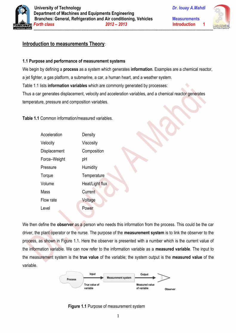
We then define the observer as a person who needs this information from the process. This could be the car
driver, the plant operator or the nurse. The purpose of the measurement system is to link the observer to the
process, as shown in Figure 1.1. Here the observer is presented with a number which is the current value of
the information variable. We can now refer to the information variable as a measured variable. The input to
the measurement system is the true value of the variable; the system output is the measured value of the
variable.
Figure 1.1 Purpose of measurement system
Observer
Measurement system
Input Output
True value of
variable
Measured value
of variable
Process
University of Technology Dr. louay A.Mahdi Department of Machines and Equipments Engineering
Branches: General, Refrigeration and Air conditioning, Vehicles Measurements Forth class 2012 – 2013 Introduction 1
------------------------------------------------------------------------------------------------------------------------------------------
2
In an ideal measurement system, the measured value would be equal to the true value. The accuracy of the
system can be defined as the closeness of the measured value to the true value. A perfectly accurate system
is a theoretical ideal and the accuracy of a real system is quantified using measurement system error E,
where
E = measured value − true value
E = system output − system input
Thus if the measured value of the flow rate of gas in a pipe is 11.0 m3/h and the true value is 11.2 m3/h, then
the error E = −0.2 m3/h. If the measured value of the rotational speed of an engine is 3140 rpm and the true
value is 3133 rpm, then E = +7 rpm. Error is the main performance indicator for a measurement system.
1.2 Structure of measurement systems
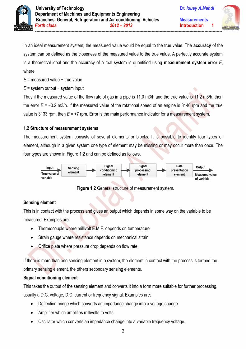
The measurement system consists of several elements or blocks. It is possible to identify four types of
element, although in a given system one type of element may be missing or may occur more than once. The
four types are shown in Figure 1.2 and can be defined as follows.
Figure 1.2 General structure of measurement system.
Sensing element
This is in contact with the process and gives an output which depends in some way on the variable to be
measured. Examples are:
Thermocouple where millivolt E.M.F. depends on temperature
Strain gauge where resistance depends on mechanical strain
Orifice plate where pressure drop depends on flow rate.
If there is more than one sensing element in a system, the element in contact with the process is termed the
primary sensing element, the others secondary sensing elements.
Signal conditioning element
This takes the output of the sensing element and converts it into a form more suitable for further processing,
usually a D.C. voltage, D.C. current or frequency signal. Examples are:
Deflection bridge which converts an impedance change into a voltage change
Amplifier which amplifies millivolts to volts
Oscillator which converts an impedance change into a variable frequency voltage.
Input Output
True value of
variableMeasured value
of variable
Sensing
element
Signal
conditioning
element
Signal
processing
element
Data
presentation
element
University of Technology Dr. louay A.Mahdi Department of Machines and Equipments Engineering
Branches: General, Refrigeration and Air conditioning, Vehicles Measurements Forth class 2012 – 2013 Introduction 1
------------------------------------------------------------------------------------------------------------------------------------------
3
Signal processing element
This takes the output of the conditioning element and converts it into a form more suitable for presentation.
Examples are:
Analogue-to-digital converter (ADC) which converts a voltage into a digital form for input to a computer
Computer which calculates the measured value of the variable from the incoming digital data.
Typical calculations are:
Computation of total mass of product gas from flow rate and density data
Integration of chromatograph peaks to give the composition of a gas stream
Correction for sensing element non-linearity.
Data presentation element
This presents the measured value in a form which can be easily recognized by the observer. Examples are:
Simple pointer–scale indicator
Chart recorder
Alphanumeric display
Visual display unit (VDU).
1.3 Examples of measurement systems
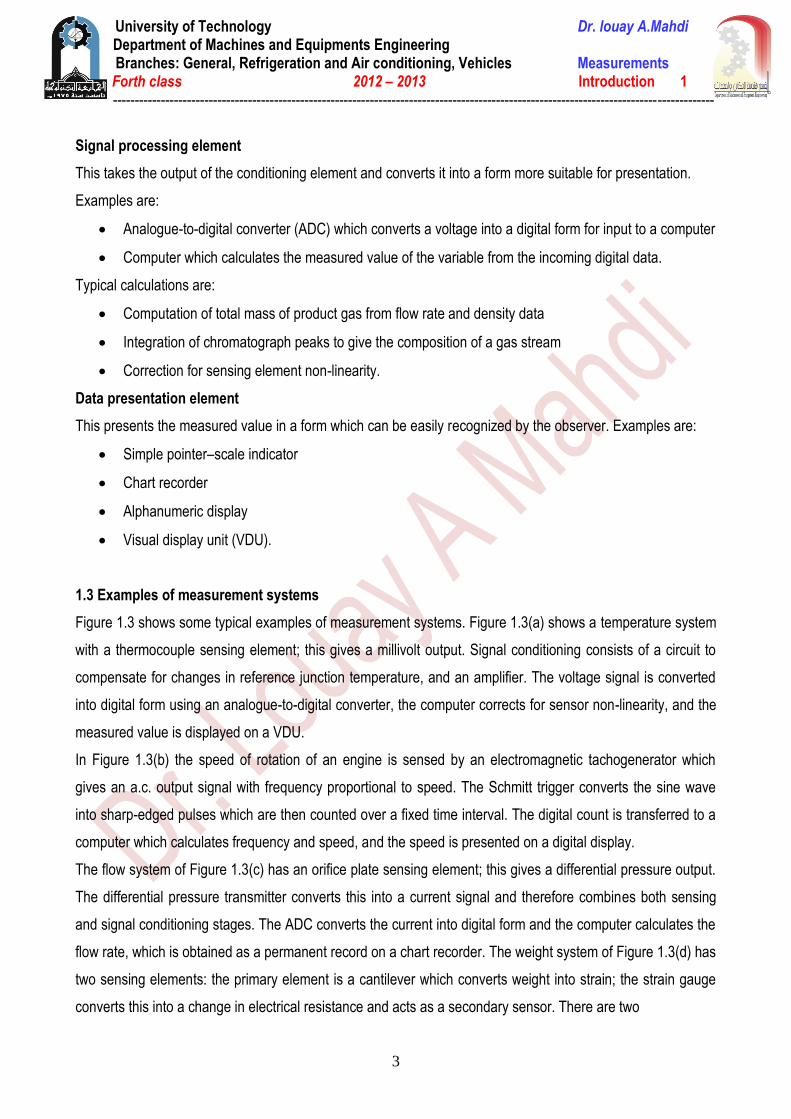
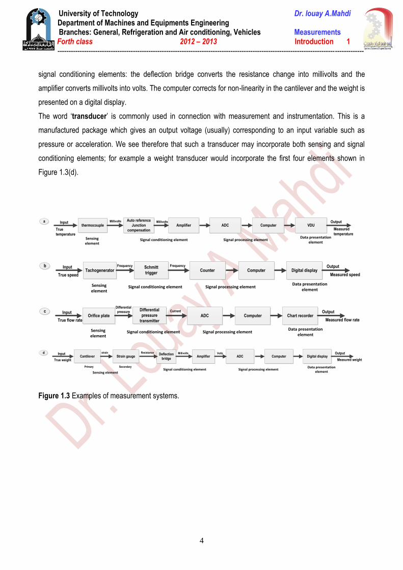
Figure 1.3 shows some typical examples of measurement systems. Figure 1.3(a) shows a temperature system
with a thermocouple sensing element; this gives a millivolt output. Signal conditioning consists of a circuit to
compensate for changes in reference junction temperature, and an amplifier. The voltage signal is converted
into digital form using an analogue-to-digital converter, the computer corrects for sensor non-linearity, and the
measured value is displayed on a VDU.
In Figure 1.3(b) the speed of rotation of an engine is sensed by an electromagnetic tachogenerator which
gives an a.c. output signal with frequency proportional to speed. The Schmitt trigger converts the sine wave
into sharp-edged pulses which are then counted over a fixed time interval. The digital count is transferred to a
computer which calculates frequency and speed, and the speed is presented on a digital display.
The flow system of Figure 1.3(c) has an orifice plate sensing element; this gives a differential pressure output.
The differential pressure transmitter converts this into a current signal and therefore combines both sensing
and signal conditioning stages. The ADC converts the current into digital form and the computer calculates the
flow rate, which is obtained as a permanent record on a chart recorder. The weight system of Figure 1.3(d) has
two sensing elements: the primary element is a cantilever which converts weight into strain; the strain gauge
converts this into a change in electrical resistance and acts as a secondary sensor. There are two
University of Technology Dr. louay A.Mahdi Department of Machines and Equipments Engineering
Branches: General, Refrigeration and Air conditioning, Vehicles Measurements Forth class 2012 – 2013 Introduction 1
------------------------------------------------------------------------------------------------------------------------------------------
4
signal conditioning elements: the deflection bridge converts the resistance change into millivolts and the
amplifier converts millivolts into volts. The computer corrects for non-linearity in the cantilever and the weight is
presented on a digital display.
The word ‘transducer’ is commonly used in connection with measurement and instrumentation. This is a
manufactured package which gives an output voltage (usually) corresponding to an input variable such as
pressure or acceleration. We see therefore that such a transducer may incorporate both sensing and signal
conditioning elements; for example a weight transducer would incorporate the first four elements shown in
Figure 1.3(d).
Figure 1.3 Examples of measurement systems.
Measured speed
Input
True speedTachogenerator
Sensing element
Frequency Schmitt
trigger
Signal conditioning element
Counter
Signal processing element
ComputerOutput
Digital display
Data presentation element
b Frequency
Measured
temperature
Input
True
temperature
thermocouple
Sensing element
Millivolts Auto reference
Junction
compensation
AmplifierMillivolts
Signal conditioning element
ADC
Signal processing element
ComputerOutput
VDU
Data presentation element
a
Measured flow rate
Input
True flow rateOrifice plate
Sensing element
Differential
pressure Differential
pressure
transmitter
Signal conditioning element
ADC
Signal processing element
ComputerOutput
Chart recorder
Data presentation element
c Current
Measured weight
Input
True weightCantilever
Sensing element
strain Deflection
bridgeAmplifier
Millivolts
Signal conditioning element
ADC
Signal processing element
ComputerOutput
Digital display
Data presentation element
dStrain gauge
Primary Secondary
Resistance Volts
University of Technology Dr. louay A.Mahdi Department of Machines and Equipments Engineering
Branches: General, Refrigeration and Air conditioning, Vehicles Measurements Forth class 2012 – 2013 Introduction 1
------------------------------------------------------------------------------------------------------------------------------------------
5
Calibration:
Principles of Calibration
Calibration consists of comparing the output of the instrument or sensor under test against the output of an
instrument of known accuracy when the same input (the measured quantity) is applied to both instruments.
This procedure is carried out for a range of inputs covering the whole measurement range of the instrument or
sensor. Calibration ensures that the measuring accuracy of all instruments and sensors used in a
measurement system is known over the whole measurement range, provided that the calibrated instruments
and sensors are used in environmental conditions that are the same as those under which they were
calibrated. For use of instruments and sensors under different environmental conditions, appropriate correction
has to be made for the ensuing modifying inputs. Whether applied to instruments or sensors, calibration
procedures are identical, and hence only the term instrument will be with the understanding that whatever is
said for instruments applies equally well to single measurement sensors.
Instruments used as a standard in calibration procedures are usually chosen to be of greater inherent
accuracy than the process instruments that they are used to calibrate. Because such instruments are only
used for calibration purposes, greater accuracy can often be achieved by specifying a type of instrument that
would be unsuitable for normal process measurements. In practice, high-accuracy, null-type instruments are
used very commonly for calibration duties, as the need for a human operator is not a problem in these
circumstances.
Instrument calibration has to be repeated at prescribed intervals because the characteristics of any instrument
change over a period. Changes in instrument characteristics are brought about by such factors as mechanical
wear, and the effects of dirt, dust, fumes, chemicals, and temperature change in the operating environment. To
a great extent, the magnitude of the drift in characteristics depends on the amount of use an instrument
receives and hence on the amount of wear and the length of time that it is subjected to the operating
environment. However, some drift also occurs even in storage as a result of aging effects in components within
the instrument.
The type of instrument, its frequency of use, and the prevailing environmental conditions all strongly
influence the calibration frequency necessary, and because so many factors are involved, it is difficult or even
impossible to determine the required frequency of instrument recalibration from theoretical considerations.
Instead, practical experimentation has to be applied to determine the rate of such changes. Once the
maximum permissible measurement error has been defined, knowledge of the rate at which the characteristics
of an instrument change allows a time interval to be calculated that represents the moment in time when an
instrument will have reached the bounds of its acceptable performance level. The instrument must be
recalibrated either at this time or earlier. This measurement error level that an instrument reaches just before
recalibration is the error bound that must be quoted in the documented specifications for the instrument.
University of Technology Dr. louay A.Mahdi Department of Machines and Equipments Engineering
Branches: General, Refrigeration and Air conditioning, Vehicles Measurements Forth class 2012 – 2013 Introduction 1
------------------------------------------------------------------------------------------------------------------------------------------
6
Control of Calibration Environment
Any instrument used as a standard in calibration procedures must be kept solely for calibration duties and
must never be used for other purposes. Most particularly, it must not be regarded as a spare instrument that
can be used for process measurements if the instrument normally used for that purpose breaks down. Proper
provision for process instrument failures must be made by keeping a spare set of process instruments.
Standard calibration instruments must be totally separate.
To ensure that these conditions are met, the calibration function must be managed and executed in a
professional manner. This will normally mean setting aside a particular place within the instrumentation
department of a company where all calibration operations take place and where all instruments used for
calibration are kept. As far as possible this should take the form of a separate room rather than a sectioned-off
area in a room used for other purposes as well. This will enable better environmental control to be applied in
the calibration area and will also offer better protection against unauthorized handling or use of calibration
instruments. The level of environmental control required during calibration should be considered carefully with
due regard to what level of accuracy is required in the calibration procedure, but should not be over specified,
as this will lead to unnecessary expense. Full air conditioning is not normally required for calibration at this
level, as it is very expensive, but sensible precautions should be taken to guard the area from extremes of heat
or cold; also, good standards of cleanliness should be maintained.
While it is desirable that all calibration functions are performed in this carefully controlled environment, it is not
always practical to achieve this. Sometimes, it is not convenient or possible to remove instruments from a
process plant, and in these cases, it is standard practice to calibrate them in situ. In these circumstances,
appropriate corrections must be made for the deviation in the calibration environmental conditions away from
those specified. This practice does not obviate the need to protect calibration instruments and maintain them in
constant conditions in a calibration laboratory at all times other than when they are involved in such calibration
duties on plant.
As far as management of calibration procedures is concerned, it is important that the performance of all
calibration operations is assigned as the clear responsibility of just one person. That person should have total
control over the calibration function and be able to limit access to the calibration laboratory to designated,
approved personnel only. Only by giving this appointed person total control over the calibration function can
the function be expected to operate efficiently and effectively. Lack of such definite management can only lead
to unintentional neglect of the calibration system, resulting in the use of equipment in an out-of-date state of
calibration and subsequent loss of traceability to reference standards.
Professional management is essential so that the customer can be assured that an efficient calibration system
is in operation and that the accuracy of measurements is guaranteed.
University of Technology Dr. louay A.Mahdi Department of Machines and Equipments Engineering
Branches: General, Refrigeration and Air conditioning, Vehicles Measurements Forth class 2012 – 2013 Introduction 1
------------------------------------------------------------------------------------------------------------------------------------------
7
Calibration procedures that relate in any way to measurements used for quality control functions are controlled
by the international standard ISO 9000 (this subsumes the old British quality standard BS 5750). One of the
clauses in ISO 9000 requires that all persons using calibration equipment be adequately trained. The manager
in charge of the calibration function is clearly responsible for ensuring that this condition is met. Training must
be adequate and targeted at the particular needs of the calibration systems involved. People must understand
what they need to know and especially why they must have this information. Successful completion of training
courses should be marked by the award of qualification certificates. These attest to the proficiency of
personnel involved in calibration duties and are a convenient way of demonstrating that the ISO 9000 training
requirement has been satisfied.
Calibration Chain and Traceability
The calibration facilities provided within the instrumentation department of a company provide the first link in
the calibration chain. Instruments used for calibration at this level are known as working standards. As such,
working standard instruments are kept by the instrumentation department of a company solely for calibration
duties, and for no other purpose, and then it can be assumed that they will maintain their accuracy over a
reasonable period of time because use-related deterioration in accuracy is largely eliminated. However, over
the longer term, the characteristics of even such standard instruments will drift, mainly due to aging effects in
components within them. Therefore, over this longer term, a program must be instituted for calibrating working
standard instruments at appropriate intervals of time against instruments of yet higher accuracy. The
instrument used for calibrating working standard instruments is known as a secondary reference standard.
This must obviously be a very well-engineered instrument that gives high accuracy and is stabilized against
drift in its performance with time. This implies that it will be an expensive instrument to buy. It also requires that
the environmental conditions in which it is used be controlled carefully in respect of ambient temperature,
humidity, and so on.
When the working standard instrument has been calibrated by an authorized standards laboratory, a
calibration certificate will be issued. This will contain at least the following information:
identification of the equipment calibrated
calibration results obtained
measurement uncertainty
any use limitations on the equipment calibrated
date of calibration
authority under which the certificate is issued
The establishment of a company standards laboratory to provide a calibration facility of the required quality is
economically viable only in the case of very large companies where large numbers of instruments need to be
University of Technology Dr. louay A.Mahdi Department of Machines and Equipments Engineering
Branches: General, Refrigeration and Air conditioning, Vehicles Measurements Forth class 2012 – 2013 Introduction 1
------------------------------------------------------------------------------------------------------------------------------------------
8
calibrated across several factories. In the case of small to medium size companies, the cost of buying and
maintaining such equipment is not justified.
Instead, they would normally use the calibration service provided by various companies that specialize in
offering a standards laboratory. What these specialist calibration companies do effectively is to share out the
high cost of providing this highly accurate but infrequently used calibration service over a large number of
companies. Such standards laboratories are closely monitored by national standards organizations.
National standards organizations usually monitor both instrument calibration and mechanical testing
laboratories. The national standards organizations lay down strict conditions that a standards laboratory has to
meet before it is approved. These conditions control laboratory management, environment, equipment, and
documentation. The person appointed as head of the laboratory must be suitably qualified, and independence
of operation of the laboratory must be guaranteed. The management structure must be such that any pressure
to rush or skip calibration procedures for production reasons can be resisted. As far as the laboratory
environment is concerned, proper temperature and humidity control must be provided, and high standards of
cleanliness and housekeeping must be maintained. All equipment used for calibration purposes must be
maintained to reference standards and supported by calibration certificates that establish this traceability.
Finally, full documentation must be maintained. This should describe all calibration procedures, maintain an
index system for recalibration of equipment, and include a full inventory of apparatus and traceability
schedules. Having met these conditions, a standards laboratory becomes an accredited laboratory for
providing calibration services and issuing calibration certificates. This accreditation is reviewed at
approximately 12 monthly intervals to ensure that the laboratory is continuing to satisfy the conditions for
approval laid down.
Primary reference standards, describe the highest level of accuracy achievable in the measurement of any
particular physical quantity. All items of equipment used in standards laboratories as secondary reference
standards have to be calibrated themselves against primary reference standards at appropriate intervals of
time. This procedure is acknowledged by the issue of a calibration certificate in the standard way.
National standards organizations maintain suitable facilities for this calibration. In the United States, this is the
National Bureau of Standards, and in the United Kingdom it is the National Physical Laboratory. Similar
national standards organizations exist in many other countries. In certain cases, such primary reference
standards can be located outside national standards organizations. For instance, the primary reference
standard for dimension measurement is defined by the wavelength of the orange-red line of krypton light, and
it can therefore be realized in any laboratory equipped with an interferometer. In certain cases (e.g., the
measurement of viscosity), such primary reference standards are not available and reference standards for
calibration are achieved by collaboration between several national standards organizations who perform
University of Technology Dr. louay A.Mahdi Department of Machines and Equipments Engineering
Branches: General, Refrigeration and Air conditioning, Vehicles Measurements Forth class 2012 – 2013 Introduction 1
------------------------------------------------------------------------------------------------------------------------------------------
9
measurements on identical samples under controlled conditions [ISO 5725 (1994) and ISO 5725-2/Cor1
(2002)].
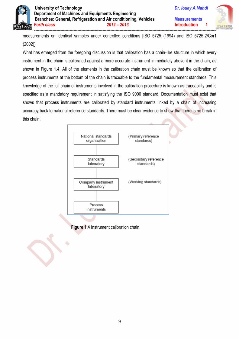
What has emerged from the foregoing discussion is that calibration has a chain-like structure in which every
instrument in the chain is calibrated against a more accurate instrument immediately above it in the chain, as
shown in Figure 1.4. All of the elements in the calibration chain must be known so that the calibration of
process instruments at the bottom of the chain is traceable to the fundamental measurement standards. This
knowledge of the full chain of instruments involved in the calibration procedure is known as traceability and is
specified as a mandatory requirement in satisfying the ISO 9000 standard. Documentation must exist that
shows that process instruments are calibrated by standard instruments linked by a chain of increasing
accuracy back to national reference standards. There must be clear evidence to show that there is no break in
this chain.
Figure 1.4 Instrument calibration chain
University of Technology Dr. louay A.Mahdi Department of Machines and Equipments Engineering
Branches: General, Refrigeration and Air conditioning, Vehicles Measurements Forth class 2012 – 2013 Introduction 1
------------------------------------------------------------------------------------------------------------------------------------------
10
Example of micrometers typical calibration chain:
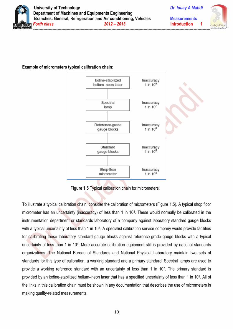
Figure 1.5 Typical calibration chain for micrometers.
To illustrate a typical calibration chain, consider the calibration of micrometers (Figure 1.5). A typical shop floor
micrometer has an uncertainty (inaccuracy) of less than 1 in 104. These would normally be calibrated in the
instrumentation department or standards laboratory of a company against laboratory standard gauge blocks
with a typical uncertainty of less than 1 in 105. A specialist calibration service company would provide facilities
for calibrating these laboratory standard gauge blocks against reference-grade gauge blocks with a typical
uncertainty of less than 1 in 106. More accurate calibration equipment still is provided by national standards
organizations. The National Bureau of Standards and National Physical Laboratory maintain two sets of
standards for this type of calibration, a working standard and a primary standard. Spectral lamps are used to
provide a working reference standard with an uncertainty of less than 1 in 107. The primary standard is
provided by an iodine-stabilized helium–neon laser that has a specified uncertainty of less than 1 in 109. All of
the links in this calibration chain must be shown in any documentation that describes the use of micrometers in
making quality-related measurements.

University of Technology Dr. louay A.Mahdi Department of Machines and Equipments Engineering
Branches: General, Refrigeration and Air conditioning, Vehicles Measurements Forth class 2012 – 2013 Introduction 1
------------------------------------------------------------------------------------------------------------------------------------------
11
Calibration Records
An essential element in the maintenance of measurement systems and the operation of calibration procedures
is the provision of full documentation. This must give a full description of the measurement requirements
throughout the workplace, instruments used, and calibration system and procedures operated. Individual
calibration records for each instrument must be included within this.
This documentation is a necessary part of the quality manual, although it may exist physically as a separate
volume if this is more convenient. An overriding constraint on the style in which the documentation is
presented is that it should be simple and easy to read. This is often facilitated greatly by a copious use of
appendices.
The starting point in the documentation must be a statement of what measurement limits have been defined
for each measurement system documented. Such limits are established by balancing the costs of improved
accuracy against customer requirements, and also with regard to what overall quality level has been specified
in the quality manual. The technical procedures required for this, which involve assessing the type and
magnitude of relevant measurement errors.
Instruments specified for each measurement situation must be listed next. This list must be accompanied by
full instructions about the proper use of the instruments concerned. These instructions will include details
about any environmental control or other special precautions that must be taken to ensure that the instruments
provide measurements of sufficient accuracy to meet the measurement limits defined. The proper training
courses appropriate to plant personnel who will use the instruments must be specified.
Having disposed of the question about what instruments are used, documentation must go on to cover the
subject of calibration. Full calibration is not applied to every measuring instrument used in a workplace
because ISO 9000 acknowledges that formal calibration procedures are not necessary for some equipment
where it is uneconomic or technically unnecessary because the accuracy of the measurement involved has an
insignificant effect on the overall quality target for a product. However, any equipment excluded from
calibration procedures in this manner must be specified as such in the documentation. Identification of
equipment that is in this category is a matter of informed judgment.
For instruments that are the subject of formal calibration, documentation must specify what standard
instruments are to be used for the purpose and define a formal procedure of calibration. This procedure must
include instructions for the storage and handling of standard calibration instruments and specify the required
environmental conditions under which calibration is to be performed. Where a calibration procedure for a
particular instrument uses published standard practices, it is sufficient to include reference to that standard
procedure in the documentation rather than to reproduce the whole procedure. Whatever calibration system is
established, a formal review procedure must be defined in the documentation that ensures its continued
effectiveness at regular intervals. The results of each review must also be documented in a formal way.

University of Technology Dr. louay A.Mahdi Department of Machines and Equipments Engineering
Branches: General, Refrigeration and Air conditioning, Vehicles Measurements Forth class 2012 – 2013 Introduction 1
------------------------------------------------------------------------------------------------------------------------------------------
12
A standard format for the recording of calibration results should be defined in the documentation. A separate
record must be kept for every instrument present in the workplace, irrespective of whether the instrument is
normally in use or is just kept as a spare. A form similar to that shown in Figure 4.3 should be used that
includes details of the instrument’s description, required calibration frequency, date of each calibration, and
calibration results on each occasion. Where appropriate, documentation must also define the manner in which
calibration results are to be recorded on the instruments themselves.
Documentation must specify procedures that are to be followed if an instrument is found to be outside the
calibration limits. This may involve adjustment, redrawing its scale, or withdrawing an instrument, depending
on the nature of the discrepancy and the type of instrument involved. Instruments withdrawn will either be
repaired or be scrapped. In the case of withdrawn instruments, a formal procedure for marking them as such
must be defined to prevent them being put back into use accidentally.
Two other items must also be covered by the calibration document. A)The traceability of the calibration
system back to national reference standards must be defined and supported by calibration certificates (figure
1.6). B)Training procedures must also be documented, specifying the particular training courses to be attended
by various personnel and what, if any, refresher courses are required.
Figure 1.6 Example of temperature calibration simple.
University of Technology Dr. louay A.Mahdi Department of Machines and Equipments Engineering
Branches: General, Refrigeration and Air conditioning, Vehicles Measurements Forth class 2012 – 2013 Introduction 1
------------------------------------------------------------------------------------------------------------------------------------------
13
Definitions and classification of variables:
Measurement Units
The first measurement units were those used in barter trade to quantify the amounts being exchanged and to
establish clear rules about the relative values of different commodities. Such early systems of measurement
were based on whatever was available as a measuring unit. For purposes of measuring length, the human
torso was a convenient tool and gave us units of the hand, the foot, and the cubit. Although generally
adequate for barter trade systems, such measurement units are, of course, imprecise, varying as they do from
one person to the next. Therefore, there has been a progressive movement toward measurement units that
are defined much more accurately.
The first improved measurement unit was a unit of length (the meter) defined as 10 -7 times the polar quadrant
of the earth. A platinum bar made to this length was established as a standard of length in the early part of the
19th century. This was superseded by a superior quality standard bar in 1889, manufactured from a platinum–
iridium alloy. Since that time, technological research has enabled further improvements to be made in the
standard used for defining length. First, in 1960, a standard meter was redefined in terms of 1.65076373 x10⁶
wavelengths of the radiation from krypton-86 in vacuum. More recently, in 1983, the meter was redefined yet
again as the length of path traveled by light in an interval of 1/299,792,458 seconds. In a similar fashion,
standard units for the measurement of other physical quantities have been defined and progressively improved
over the years. The latest standards for defining the units used for measuring a range of physical variables are
given in Table 1.1.
The early establishment of standards for the measurement of physical quantities proceeded in several
countries at broadly parallel times; in consequence, several sets of units emerged for measuring the same
physical variable. For instance, length can be measured in yards, meters, or several other units. Apart from the
major units of length, subdivisions of standard units exist such as feet, inches, centimeters, and millimeters,
with a fixed relationship between each fundamental unit and its subdivisions. Yards, feet, and inches belong to
the Imperial system of units, which is characterized by having varying and cumbersome multiplication factors
relating fundamental units to subdivisions such
as 1760 (miles to yards), 3 (yards to feet), and 12 (feet to inches). The metric system is an alternative set of
units, which includes, for instance, the unit of the meter and its centimeter and millimeter subdivisions for
measuring length. All multiples and subdivisions of basic metric units are related to the base by factors of 10
and such units are therefore much easier to use than Imperial units. However, in the case of derived units such
as velocity, the number of alternative ways in which these can be expressed in the metric system can lead to
confusion.

University of Technology Dr. louay A.Mahdi Department of Machines and Equipments Engineering
Branches: General, Refrigeration and Air conditioning, Vehicles Measurements Forth class 2012 – 2013 Introduction 1
------------------------------------------------------------------------------------------------------------------------------------------
14
Table 1.1 Definitions of Standard Units
(a) Fundamental Units
Physical Quantity
Standard Definition
Length Meter/
symbol
Length of path traveled by light in an interval of 1/299,792,458 seconds
Mass Kilogram
kg
Mass of a platinum–iridium cylinder kept in the International Bureau of Weights
and Measures, Sevres, Paris
Time Second
s
9.192631770 x10⁹ cycles of radiation from vaporized cesium 133 (an accuracy
of 1 in 1012 or one second in 36,000 years)
Temperature Degrees
K
Temperature difference between absolute zero Kelvin and the triple point of
water is defined as 273.16 K
Current Amphere
A
One ampere is the current flowing through two infinitely long parallel conductors
of negligible cross section placed 1 meter apart in vacuum and producing a
force of 2 x 10 -7 newtons per meter length of conductor
Luminous
intensity
Candela
cd
source emitting monochromatic radiation at a frequency of 540 terahertz (Hz x
1012) and with a radiant density in that direction of 1.4641 mW/steradian (1
steradian is the solid angle, which, having its vertex at the center of a sphere,
cuts off an area of the sphere surface equal to that of a square with sides of
length equal to the sphere radius)
Matter Mole
mol
Number of atoms in a 0.012-kg mass of carbon 12
(b) Supplementary Fundamental Units
Plane angle Radian
rad
Solid angle Steradian
sr
As a result of this, an internationally agreed set of standard units (SI units or Syste`mes internationales
d’unite´s) has been defined, and strong efforts are being made to encourage the adoption of this system
throughout the world. In support of this effort, the SI system of units is used exclusively in this book. However,
it should be noted that the Imperial system is still widely used in the engineering industry, particularly in the
United States. The full range of fundamental SI measuring units and the further set of units derived from them
are given in Tables 1.1 and 1.2.
University of Technology Dr. louay A.Mahdi Department of Machines and Equipments Engineering
Branches: General, Refrigeration and Air conditioning, Vehicles Measurements Forth class 2012 – 2013 Introduction 1
------------------------------------------------------------------------------------------------------------------------------------------
15
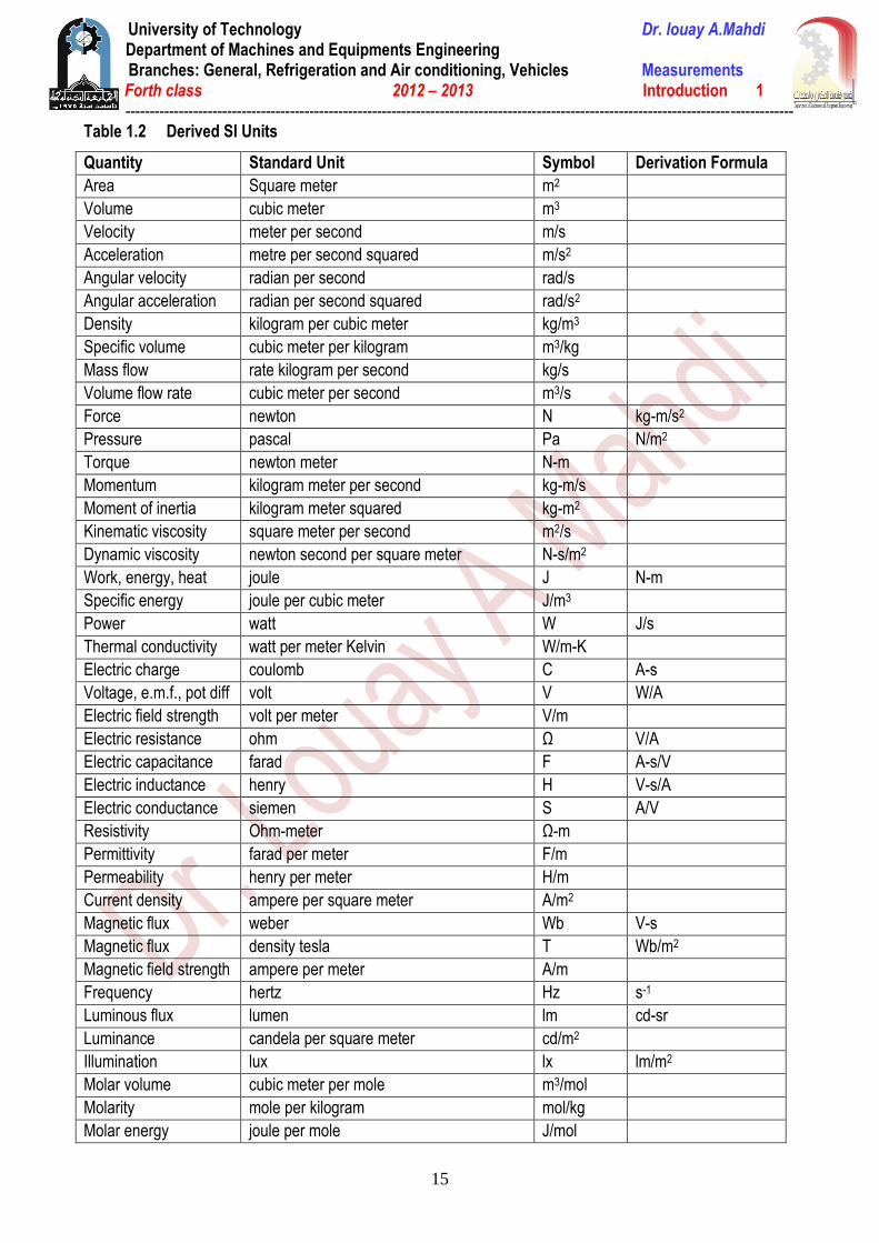
Table 1.2 Derived SI Units
Quantity Standard Unit Symbol Derivation Formula
Area Square meter m2
Volume cubic meter m3
Velocity meter per second m/s
Acceleration metre per second squared m/s2
Angular velocity radian per second rad/s
Angular acceleration radian per second squared rad/s2
Density kilogram per cubic meter kg/m3
Specific volume cubic meter per kilogram m3/kg
Mass flow rate kilogram per second kg/s
Volume flow rate cubic meter per second m3/s
Force newton N kg-m/s2
Pressure pascal Pa N/m2
Torque newton meter N-m
Momentum kilogram meter per second kg-m/s
Moment of inertia kilogram meter squared kg-m2
Kinematic viscosity square meter per second m2/s
Dynamic viscosity newton second per square meter N-s/m2
Work, energy, heat joule J N-m
Specific energy joule per cubic meter J/m3
Power watt W J/s
Thermal conductivity watt per meter Kelvin W/m-K
Electric charge coulomb C A-s
Voltage, e.m.f., pot diff volt V W/A
Electric field strength volt per meter V/m
Electric resistance ohm Ω V/A
Electric capacitance farad F A-s/V
Electric inductance henry H V-s/A
Electric conductance siemen S A/V
Resistivity Ohm-meter Ω-m
Permittivity farad per meter F/m
Permeability henry per meter H/m
Current density ampere per square meter A/m2
Magnetic flux weber Wb V-s
Magnetic flux density tesla T Wb/m2
Magnetic field strength ampere per meter A/m
Frequency hertz Hz s-1
Luminous flux lumen lm cd-sr
Luminance candela per square meter cd/m2
Illumination lux lx lm/m2
Molar volume cubic meter per mole m3/mol
Molarity mole per kilogram mol/kg
Molar energy joule per mole J/mol