Embed Size (px)
Citation preview

Irish StandardI.S. EN 60076-19:2015
Power transformers - Part 19: Rules for thedetermination of uncertainties in themeasurement of the losses on powertransformers and reactors
© CENELEC 2015 No copying without NSAI permission except as permitted by copyright law.
Thi
s is
a fr
ee 4
7 pa
ge s
ampl
e. A
cces
s th
e fu
ll ve
rsio
n on
line.

I.S. EN 60076-19:2015I.S. EN 60076-19:2015
Incorporating amendments/corrigenda/National Annexes issued since publication:
The National Standards Authority of Ireland (NSAI) produces the following categories of formal documents:
I.S. xxx: Irish Standard — national specification based on the consensus of an expert panel and subject to public consultation.
S.R. xxx: Standard Recommendation — recommendation based on the consensus of an expert panel and subject to public consultation.
SWiFT xxx: A rapidly developed recommendatory document based on the consensus of the participants of an NSAI workshop.
This document replaces/revises/consolidates the NSAI adoption of the document(s) indicated on theCEN/CENELEC cover/Foreword and the following National document(s):
NOTE: The date of any NSAI previous adoption may not match the date of its original CEN/CENELECdocument.
This document is based on:
EN 60076-19:2015
Published:
2015-08-28
This document was publishedunder the authority of the NSAIand comes into effect on:
2015-09-15
ICS number:
NOTE: If blank see CEN/CENELEC cover page
NSAI1 Swift Square, Northwood, Santry Dublin 9
T +353 1 807 3800 F +353 1 807 3838 E [email protected] W NSAI.ie
Sales:T +353 1 857 6730 F +353 1 857 6729 W standards.ie
Údarás um Chaighdeáin Náisiúnta na hÉireann
Thi
s is
a fr
ee 4
7 pa
ge s
ampl
e. A
cces
s th
e fu
ll ve
rsio
n on
line.

National ForewordNational Foreword
I.S. EN 60076-19:2015 is the adopted Irish version of the European Document EN 60076-19:2015, Powertransformers - Part 19: Rules for the determination of uncertainties in the measurement of the losses onpower transformers and reactors
This document does not purport to include all the necessary provisions of a contract. Users are responsiblefor its correct application.
Compliance with this document does not of itse lf confer immunity from legal obligations .Compliance with this document does not of itse lf confer immunity from legal obligations .
In line with international standards practice the decimal point is shown as a comma (,) throughout thisdocument.
Thi
s is
a fr
ee 4
7 pa
ge s
ampl
e. A
cces
s th
e fu
ll ve
rsio
n on
line.

This page is intentionally left blank
Thi
s is
a fr
ee 4
7 pa
ge s
ampl
e. A
cces
s th
e fu
ll ve
rsio
n on
line.

EUROPEAN STANDARD
NORME EUROPÉENNE
EUROPÄISCHE NORM
EN 60076-19
August 2015
ICS 29.180
English Version
Power transformers - Part 19: Rules for the determination of uncertainties in the measurement of the losses on power
transformers and reactors (IEC/TS 60076-19:2013 , modified)
Transformateurs de puissance - Partie 19: Règles pour la détermination des incertitudes de mesure des pertes des
transformateurs de puissance et bobines d'inductance (IEC/TS 60076-19:2013 , modifiée)
Leistungstransformatoren - Teil 19: Regeln für die Bestimmung von Unsicherheiten in der Messung der
Verluste von Leistungstransformatoren und Drosselspulen (IEC/TS 60076-19:2013 , modifiziert)
This European Standard was approved by CENELEC on 2015-06-25. CENELEC members are bound to comply with the CEN/CENELEC Internal Regulations which stipulate the conditions for giving this European Standard the status of a national standard without any alteration.
Up-to-date lists and bibliographical references concerning such national standards may be obtained on application to the CEN-CENELEC Management Centre or to any CENELEC member.
This European Standard exists in three official versions (English, French, German). A version in any other language made by translation under the responsibility of a CENELEC member into its own language and notified to the CEN-CENELEC Management Centre has the same status as the official versions.
CENELEC members are the national electrotechnical committees of Austria, Belgium, Bulgaria, Croatia, Cyprus, the Czech Republic, Denmark, Estonia, Finland, Former Yugoslav Republic of Macedonia, France, Germany, Greece, Hungary, Iceland, Ireland, Italy, Latvia, Lithuania, Luxembourg, Malta, the Netherlands, Norway, Poland, Portugal, Romania, Slovakia, Slovenia, Spain, Sweden, Switzerland, Turkey and the United Kingdom.
European Committee for Electrotechnical Standardization Comité Européen de Normalisation Electrotechnique
Europäisches Komitee für Elektrotechnische Normung
CEN-CENELEC Management Centre: Avenue Marnix 17, B-1000 Brussels
© 2015 CENELEC All rights of exploitation in any form and by any means reserved worldwide for CENELEC Members.
Ref. No. EN 60076-19:2015 E
I.S. EN 60076-19:2015T
his
is a
free
47
page
sam
ple.
Acc
ess
the
full
vers
ion
onlin
e.

EN 60076-19:2015 (E)
2
Foreword
This document (EN 60076-19:2015) consists of the text of IEC/TS 60079:2013 prepared by IEC/TC 14 "Power transformers", together with the common modifications prepared by CLC/TC 14 "Power transformers". The following dates are fixed:
• latest date by which this document has to be implemented at national level by publication of an identical national standard or by endorsement
(dop) 2016-06-25
• latest date by which the national standards conflicting with this document have to be withdrawn
(dow) 2018-06-25
Attention is drawn to the possibility that some of the elements of this document may be the subject of patent rights. CENELEC [and/or CEN] shall not be held responsible for identifying any or all such patent rights. This document has been prepared under a mandate given to CENELEC by the European Commission and the European Free Trade Association.
Endorsement notice
The text of the International Standard IEC/TS 60079:2013 was approved by CENELEC as a European Standard with agreed common modifications.
I.S. EN 60076-19:2015T
his
is a
free
47
page
sam
ple.
Acc
ess
the
full
vers
ion
onlin
e.

EN 60076-19:2015 (E)
3
COMMON MODIFICATIONS
Introduction
Modify the first paragraph as follows:
The losses of the transformers (no- load and load losses) are object of guarantee and penalty in the majority of the contracts and play an important role in the evaluation of the total (service) costs and therefore in the investments involved. Furthermore, regional regulations, such as the European Union directive for EcoDesign, may also pose requirements on establishment of reliable values for losses.
Modify the third and fourth paragraphs as follows:
Corrections and uncertainties are also considered in IEC 60076-8 where some general indications are given for their determination.
This European Standard deals with the measurement of the losses that from a measuring point of view consist of the estimate of a measurand and the evaluation of the uncertainty that affects the measurand itself. The procedures can also be applied to loss measurements on power transformers and reactors as evaluation of the achievable performance of a test facility in the course of prequalification processes, as estimations of achievable uncertainty in the enquiry stage of an order or prior to beginning final testing at manufacturer´s premises and for evaluations of market surveillance measurements.
Add before the fifth paragraph:
Evaluation of uncertainty in testing is often characterized as “top-down” or “bottom-up”, where the first one relies on inter-laboratory comparisons on a circulated test object to estimate the dispersion and hence the uncertainty. The latter method instead relies on the formulation of a model function, where the test result y is expressed as a function of input quantities. This function is often the formula used for the calculation of the result. The “bottom-up” method is applied in this Document.
Replace the sixth paragraph by:
It is recommended that guarantee and penalty calculations should refer to the best estimated values of the losses without considering the measurement uncertainties, based on a shared risk concept, where both parties are aware of and accept the consequences of non-negligible measurement uncertainty.
In cases where the losses are required to conform to stated tolerance limits, it is recommended that the estimated uncertainty is less than the tolerance limit. This situation will occur for example in market surveillance activities. In lieu of other specifications it can be noted that 3 % is often used as estimate for the required uncertainty.
Modify the eighth paragraph as follows:
Standards mentioned in the text but not indispensable are listed at the end of the document.
I.S. EN 60076-19:2015T
his
is a
free
47
page
sam
ple.
Acc
ess
the
full
vers
ion
onlin
e.
EN 60076-19:2015 (E)
4
Replace the last paragraph by:
This European document is based on IEC/TS 60076-19. The technical content of the TS was not changed, but small numerical mistakes and consistent use of symbols in Annex A were corrected. The introduction was modified to enhance clarity.
1 Scope
Modify the first paragraph as follows:
This European Standard illustrates the procedures that should be applied to evaluate the uncertainty affecting the measurements of no-load and load losses during the routine tests on power transformers.
2 Normative references
The following documents, in whole or in part, are normatively referenced in this document and are indispensable for its application. For dated references, only the edition cited applies. For undated references, the latest edition of the referenced document (including any amendments) applies.
EN 60076-1:2011, Power transformers – Part 1: General (IEC 60076-1:2011)
EN 60076-2:2011, Power transformers – Part 2: Temperature rise for liquid-immersed transformers (IEC 60076-2:2011)
I.S. EN 60076-19:2015T
his
is a
free
47
page
sam
ple.
Acc
ess
the
full
vers
ion
onlin
e.

IEC/TS 60076-19 Edition 1.0 2013-03
TECHNICAL SPECIFICATION SPÉCIFICATION TECHNIQUE
Power transformers – Part 19: Rules for the determination of uncertainties in the measurement of the losses on power transformers and reactors Transformateurs de puissance – Partie 19: Règles pour la détermination des incertitudes de mesure des pertes des transformateurs de puissance et bobines d’inductance
IEC
/TS
600
76-1
9:20
13
®
I.S. EN 60076-19:2015T
his
is a
free
47
page
sam
ple.
Acc
ess
the
full
vers
ion
onlin
e.
THIS PUBLICATION IS COPYRIGHT PROTECTED Copyright © 2013 IEC, Geneva, Switzerland All rights reserved. Unless otherwise specified, no part of this publication may be reproduced or utilized in any form or by any means, electronic or mechanical, including photocopying and microfilm, without permission in writing from either IEC or IEC's member National Committee in the country of the requester. If you have any questions about IEC copyright or have an enquiry about obtaining additional rights to this publication, please contact the address below or your local IEC member National Committee for further information. Droits de reproduction réservés. Sauf indication contraire, aucune partie de cette publication ne peut être reproduite ni utilisée sous quelque forme que ce soit et par aucun procédé, électronique ou mécanique, y compris la photocopie et les microfilms, sans l'accord écrit de la CEI ou du Comité national de la CEI du pays du demandeur. Si vous avez des questions sur le copyright de la CEI ou si vous désirez obtenir des droits supplémentaires sur cette publication, utilisez les coordonnées ci-après ou contactez le Comité national de la CEI de votre pays de résidence.
IEC Central Office Tel.: +41 22 919 02 11 3, rue de Varembé Fax: +41 22 919 03 00 CH-1211 Geneva 20 [email protected] Switzerland www.iec.ch
About the IEC The International Electrotechnical Commission (IEC) is the leading global organization that prepares and publishes International Standards for all electrical, electronic and related technologies.
About IEC publications The technical content of IEC publications is kept under constant review by the IEC. Please make sure that you have the latest edition, a corrigenda or an amendment might have been published. Useful links: IEC publications search - www.iec.ch/searchpub The advanced search enables you to find IEC publications by a variety of criteria (reference number, text, technical committee,…). It also gives information on projects, replaced and withdrawn publications. IEC Just Published - webstore.iec.ch/justpublished Stay up to date on all new IEC publications. Just Published details all new publications released. Available on-line and also once a month by email.
Electropedia - www.electropedia.org The world's leading online dictionary of electronic and electrical terms containing more than 30 000 terms and definitions in English and French, with equivalent terms in additional languages. Also known as the International Electrotechnical Vocabulary (IEV) on-line. Customer Service Centre - webstore.iec.ch/csc If you wish to give us your feedback on this publication or need further assistance, please contact the Customer Service Centre: [email protected].
A propos de la CEI La Commission Electrotechnique Internationale (CEI) est la première organisation mondiale qui élabore et publie des Normes internationales pour tout ce qui a trait à l'électricité, à l'électronique et aux technologies apparentées.
A propos des publications CEI Le contenu technique des publications de la CEI est constamment revu. Veuillez vous assurer que vous possédez l’édition la plus récente, un corrigendum ou amendement peut avoir été publié. Liens utiles: Recherche de publications CEI - www.iec.ch/searchpub La recherche avancée vous permet de trouver des publications CEI en utilisant différents critères (numéro de référence, texte, comité d’études,…). Elle donne aussi des informations sur les projets et les publications remplacées ou retirées. Just Published CEI - webstore.iec.ch/justpublished Restez informé sur les nouvelles publications de la CEI. Just Published détaille les nouvelles publications parues. Disponible en ligne et aussi une fois par mois par email.
Electropedia - www.electropedia.org Le premier dictionnaire en ligne au monde de termes électroniques et électriques. Il contient plus de 30 000 termes et définitions en anglais et en français, ainsi que les termes équivalents dans les langues additionnelles. Egalement appelé Vocabulaire Electrotechnique International (VEI) en ligne. Service Clients - webstore.iec.ch/csc Si vous désirez nous donner des commentaires sur cette publication ou si vous avez des questions contactez-nous: [email protected].
I.S. EN 60076-19:2015T
his
is a
free
47
page
sam
ple.
Acc
ess
the
full
vers
ion
onlin
e.
IEC/TS 60076-19 Edition 1.0 2013-03
TECHNICAL SPECIFICATION SPÉCIFICATION TECHNIQUE
Power transformers – Part 19: Rules for the determination of uncertainties in the measurement of the losses on power transformers and reactors Transformateurs de puissance – Partie 19: Règles pour la détermination des incertitudes de mesure des pertes des transformateurs de puissance et bobines d’inductance
INTERNATIONAL ELECTROTECHNICAL COMMISSION
COMMISSION ELECTROTECHNIQUE INTERNATIONALE W ICS 29.180
PRICE CODE CODE PRIX
ISBN 978-2-83220-693-5
® Registered trademark of the International Electrotechnical Commission Marque déposée de la Commission Electrotechnique Internationale
®
Warning! Make sure that you obtained this publication from an authorized distributor. Attention! Veuillez vous assurer que vous avez obtenu cette publication via un distributeur agréé.
I.S. EN 60076-19:2015T
his
is a
free
47
page
sam
ple.
Acc
ess
the
full
vers
ion
onlin
e.

– 2 – TS 60076-19 © IEC:2013
CONTENTS
FOREWORD ........................................................................................................................... 4 INTRODUCTION ..................................................................................................................... 6 1 Scope ............................................................................................................................... 7 2 Normative references ....................................................................................................... 7 3 Terms and definitions ....................................................................................................... 7 4 Symbols ........................................................................................................................... 8
4.1 General symbols ..................................................................................................... 8 4.2 Symbols for uncertainty ........................................................................................... 9
5 Power measurement, systematic deviation and uncertainty ............................................ 10 5.1 General ................................................................................................................. 10 5.2 Model function ....................................................................................................... 10 5.3 Measuring systems ................................................................................................ 10
6 Procedures for no-load loss measurement ...................................................................... 11 6.1 General ................................................................................................................. 11 6.2 Model function for no-load losses at reference conditions ...................................... 11 6.3 Uncertainty budget for no-load loss ....................................................................... 12
7 Procedures for load loss measurement ........................................................................... 13 7.1 General ................................................................................................................. 13 7.2 Model function for load loss measurement at rated current .................................... 13 7.3 Reporting to rated current and reference temperature ........................................... 14 7.4 Uncertainty budget for the measured power P2 reported to rated current .............. 14
7.4.1 General ..................................................................................................... 14 7.4.2 Uncertainties of measured load loss power P2 at ambient temperature
θ2 .............................................................................................................. 14 7.5 Uncertainty budget for reported load loss at reference temperature ....................... 15
8 Three-phase calculations ................................................................................................ 16 8.1 Power measurement .............................................................................................. 16 8.2 Reference voltage ................................................................................................. 17 8.3 Reference current.................................................................................................. 17
9 Reporting ....................................................................................................................... 17 9.1 Uncertainty declaration .......................................................................................... 17 9.2 Traceability ........................................................................................................... 17
10 Estimate of corrections and uncertainty contributions ..................................................... 18 10.1 Instrument transformers ........................................................................................ 18 10.2 Uncertainty contributions of ratio error of instrument transformers ......................... 18 10.3 Uncertainty contribution of phase displacement of instrument transformers ........... 19
10.3.1 General ..................................................................................................... 19 10.3.2 Complete reference procedure .................................................................. 19 10.3.3 Class index procedure ............................................................................... 20
10.4 Voltage and current measurements ....................................................................... 21 10.5 Power meter .......................................................................................................... 21 10.6 Correction to sinusoidal waveform ......................................................................... 22 10.7 Winding temperature at load loss measurement .................................................... 23 10.8 Winding resistance measurement .......................................................................... 23
Annex A (informative) Example of load loss uncertainty evaluation for a large power transformer ........................................................................................................................... 25
I.S. EN 60076-19:2015T
his
is a
free
47
page
sam
ple.
Acc
ess
the
full
vers
ion
onlin
e.

TS 60076-19 © IEC:2013 – 3 –
Annex B (Informative) Example of load loss uncertainty evaluation for a distribution transformer ........................................................................................................................... 33 Bibliography .......................................................................................................................... 37 Table 1 – Measured no-load loss uncertainties ..................................................................... 12 Table 2 – Measured load loss uncertainties at ambient temperature ..................................... 15 Table 3 – Absolute uncertainty of the additional losses at temperature θ2 ............................. 15 Table 4 – Absolute uncertainty of load losses PLL reported at reference temperature ........... 16 Table 5 – Procedures for the determination of phase displacement uncertainties .................. 19 Table A.1 – Transformer ratings ............................................................................................ 25 Table A.2 – Loss measurement results (one phase) .............................................................. 27 Table A.3 – Calibration of voltage and current transformers .................................................. 27 Table A.4 – Uncertainty contributions.................................................................................... 29 Table B.1 – Transformer ratings ............................................................................................ 33 Table B.2 – Measured quantities ........................................................................................... 34 Table B.3 – Calibration of the current transformers ............................................................... 35 Table B.4 – Uncertainty contribution ..................................................................................... 36
I.S. EN 60076-19:2015T
his
is a
free
47
page
sam
ple.
Acc
ess
the
full
vers
ion
onlin
e.

– 4 – TS 60076-19 © IEC:2013
INTERNATIONAL ELECTROTECHNICAL COMMISSION
____________
POWER TRANSFORMERS –
Part 19: Rules for the determination of uncertainties in the
measurement of the losses on power transformers and reactors
FOREWORD 1) The International Electrotechnical Commission (IEC) is a worldwide organization for standardization comprising
all national electrotechnical committees (IEC National Committees). The object of IEC is to promote international co-operation on all questions concerning standardization in the electrical and electronic fields. To this end and in addition to other activities, IEC publishes International Standards, Technical Specifications, Technical Reports, Publicly Available Specifications (PAS) and Guides (hereafter referred to as “IEC Publication(s)”). Their preparation is entrusted to technical committees; any IEC National Committee interested in the subject dealt with may participate in this preparatory work. International, governmental and non-governmental organizations liaising with the IEC also participate in this preparation. IEC collaborates closely with the International Organization for Standardization (ISO) in accordance with conditions determined by agreement between the two organizations.
2) The formal decisions or agreements of IEC on technical matters express, as nearly as possible, an international consensus of opinion on the relevant subjects since each technical committee has representation from all interested IEC National Committees.
3) IEC Publications have the form of recommendations for international use and are accepted by IEC National Committees in that sense. While all reasonable efforts are made to ensure that the technical content of IEC Publications is accurate, IEC cannot be held responsible for the way in which they are used or for any misinterpretation by any end user.
4) In order to promote international uniformity, IEC National Committees undertake to apply IEC Publications transparently to the maximum extent possible in their national and regional publications. Any divergence between any IEC Publication and the corresponding national or regional publication shall be clearly indicated in the latter.
5) IEC itself does not provide any attestation of conformity. Independent certification bodies provide conformity assessment services and, in some areas, access to IEC marks of conformity. IEC is not responsible for any services carried out by independent certification bodies.
6) All users should ensure that they have the latest edition of this publication.
7) No liability shall attach to IEC or its directors, employees, servants or agents including individual experts and members of its technical committees and IEC National Committees for any personal injury, property damage or other damage of any nature whatsoever, whether direct or indirect, or for costs (including legal fees) and expenses arising out of the publication, use of, or reliance upon, this IEC Publication or any other IEC Publications.
8) Attention is drawn to the Normative references cited in this publication. Use of the referenced publications is indispensable for the correct application of this publication.
9) Attention is drawn to the possibility that some of the elements of this IEC Publication may be the subject of patent rights. IEC shall not be held responsible for identifying any or all such patent rights.
The main task of IEC technical committees is to prepare International Standards. In exceptional circumstances, a technical committee may propose the publication of a technical specification when
• the required support cannot be obtained for the publication of an International Standard, despite repeated efforts, or
• the subject is still under technical development or where, for any other reason, there is the future but no immediate possibility of an agreement on an International Standard.
Technical specifications are subject to review within three years of publication to decide whether they can be transformed into International Standards.
IEC 60076-19, which is a technical specification, has been prepared by IEC technical committee 14: Power transformers.
The text of this technical specification is based on the following documents:
I.S. EN 60076-19:2015T
his
is a
free
47
page
sam
ple.
Acc
ess
the
full
vers
ion
onlin
e.

TS 60076-19 © IEC:2013 – 5 –
Enquiry draft Report on voting
14/726/DTS 14/736A/RVC
Full information on the voting for the approval of this technical specification can be found in the report on voting indicated in the above table.
This publication has been drafted in accordance with the ISO/IEC Directives, Part 2.
A list of all parts in the IEC 60076 series, published under the general title Power transformers, can be found on the IEC website.
The committee has decided that the contents of this publication will remain unchanged until the stability date indicated on the IEC web site under "http://webstore.iec.ch" in the data related to the specific publication. At this date, the publication will be
• transformed into an International Standard, • reconfirmed, • withdrawn, • replaced by a revised edition, or • amended.
I.S. EN 60076-19:2015T
his
is a
free
47
page
sam
ple.
Acc
ess
the
full
vers
ion
onlin
e.

– 6 – TS 60076-19 © IEC:2013
INTRODUCTION
The losses of the transformers (no- load and load losses) are object of guaranty and penalty in the majority of the contracts and play an important role in the evaluation of the total (service) costs and therefore in the investments involved.
According to ISO/IEC 17025 the result of any measurement should be qualified with the evaluation of its uncertainty. A further requirement is that known corrections shall have been applied before evaluation of uncertainty.
Corrections and uncertainties are also considered in IEC 60076-8 were some general indications are given for their determination.
This Technical Specification deals with the measurement of the losses that from a measuring point of view consist of the estimate of a measurand and the evaluation of the uncertainty that affects the measurand itself.
The uncertainty range depends on the quality of the test installation and measuring system, on the skill of the staff and on the intrinsic measurement difficulties presented by the tested objects.
The submitted test results are to be considered the most correct estimate and therefore this value has to be accepted as it stands.
In the annexes to this document, two examples of uncertainty calculations are reported for load loss measurements on large power and distribution transformers.
Standards, technical reports and guides mentioned in the text are listed at the end of the document.
It is stated that guaranty and penalty calculations should refer to the best estimated values of the losses without considering the measurement uncertainties.
I.S. EN 60076-19:2015T
his
is a
free
47
page
sam
ple.
Acc
ess
the
full
vers
ion
onlin
e.
TS 60076-19 © IEC:2013 – 7 –
POWER TRANSFORMERS –
Part 19: Rules for the determination of uncertainties in the measurement of the losses on power transformers and reactors
1 Scope
This part of IEC 60076, which is a Technical Specification, illustrates the procedures that should be applied to evaluate the uncertainty affecting the measurements of no-load and load losses during the routine tests on power transformers.
Even if the attention is especially paid to the transformers, when applicable the specification can be also used for the measurements of reactor losses, except large reactors with very low power factor.
2 Normative references
The following documents, in whole or in part, are normatively referenced in this document and are indispensable for its application. For dated references, only the edition cited applies. For undated references, the latest edition of the referenced document (including any amendments) applies.
IEC 60076-1:2011, Power transformers – Part 1: General
IEC 60076-2:2011, Power transformers – Part 2: Temperature rise for liquid-immersed transformers
3 Terms and definitions
For the purposes of this document, the terms and definitions given in IEC 60076-1 and 60076-2, as well as the following apply.
NOTE The following terms and definitions were taken from ISO/IEC Guide 98-3:2008.
3.1 uncertainty (of measurement) parameter, associated with the result of a measurement, that characterizes the dispersion of the values that could reasonably be attributed to the measurand
[SOURCE: ISO/IEC Guide 98-3:2008, 2.2.3]
3.2 standard uncertainty uncertainty of the result of a measurement expressed as a standard deviation
[SOURCE: ISO/IEC Guide 98-3:2008, 2.3.1]
3.3 type A evaluation (of uncertainty) method of evaluation of uncertainty by the statistical analysis of series of observations
[SOURCE: ISO/IEC Guide 98-3:2008, 2.3.2]
I.S. EN 60076-19:2015T
his
is a
free
47
page
sam
ple.
Acc
ess
the
full
vers
ion
onlin
e.
– 8 – TS 60076-19 © IEC:2013
3.4 type B evaluation (of uncertainty) method of evaluation of uncertainty by means other than the statistical analysis of series of observations
[SOURCE: ISO/IEC Guide 98-3:2008, 2.3.3]
3.5 combined standard uncertainty standard uncertainty of the result of measurement when that result is obtained from the values of a number of other quantities, equal to the positive square root of a sum of terms, the terms being the variances or covariances of these other quantities weighted according to how the measurement result varies with changes in these quantities
[SOURCE: ISO/IEC Guide 98-3:2008, 2.3.4]
3.6 expanded uncertainty quantity defining an interval about the result of a measurement that may be expected to encompass a large fraction of the distribution of values that could reasonably be attributed to the measurand
[SOURCE: ISO/IEC Guide 98-3:2008, 2.3.5]
3.7 coverage factor numerical factor used as a multiplier of the combined standard uncertainty in order to obtain an expanded uncertainty
[SOURCE: ISO/IEC Guide 98-3:2008, 2.3.6]
4 Symbols
4.1 General symbols
DF Parameter related to correction of power for phase displacement in measuring circuit
MI Current measured by the ammeter (preferably rated current)
NI Reference current (normally corresponding to rated current)
CNk Rated transformation ratio of the current transformer
VNk Rated transformation ratio of the voltage transformer
P Power
2P Power measured at the load loss measurement corrected for known systematic deviations and referred to the current NI
LLP Load loss at reference conditions
NLLP No-load loss at reference conditions and corrected for known errors in the measurement
n Exponent related to the non-linear behaviour of no-load loss
WP Power measured by the power meter
arP Additional losses at reference temperature
2aP Additional losses at temperature 2θ
I.S. EN 60076-19:2015T
his
is a
free
47
page
sam
ple.
Acc
ess
the
full
vers
ion
onlin
e.

TS 60076-19 © IEC:2013 – 9 –
1R Equivalent resistance of the windings at temperature 1θ according to IEC 60076-1
2R Equivalent resistance of the windings at temperature 2θ
rR Equivalent resistance of the windings at reference temperature
t Parameter related to the thermal coefficient of winding resistance
avgU Voltage measured with an instrument having average rectified mean response
MU Voltage measured
NU Rated voltage
rmsU Voltage measured using an instrument with true r.m.s. response
θ Temperature (expressed in degrees Celsius)
1θ Temperature of transformer winding at cold winding resistance test according to IEC 60076-1
2θ Temperature of transformer windings during load loss test (expressed in Celsius degrees)
rθ Reference temperature for transformer windings according to IEC 60076-1
Cϕ∆ Actual phase displacement of the current transformer (rad)
Pϕ∆ Actual phase displacement of the power meter (rad)
Vϕ∆ Actual phase displacement of the voltage transformer (rad)
Cε Actual ratio error of the current transformer (%)
Vε Actual ratio error of the voltage transformer (%)
ϕ Actual phase angle between voltage and current (rad)
Mϕ Phase angle between voltage and current measured with power meter (rad)
4.2 Symbols for uncertainty
c Sensitivity factor for contribution to uncertainty
u Standard uncertainty
u Absolute standard uncertainty
U Expanded uncertainty
U Absolute expanded uncertainty
Cu Uncertainty of current transformer ratio (expressed in percent of the ratio)
IMu Uncertainty of current measurement
LLu Uncertainty of the load loss at reference temperature
NLLu Uncertainty of the no-load loss
2Pu Uncertainty of 2P
FDu Uncertainty of term DF
PWu Uncertainty of the power indicated by the analyzer
1Ru Uncertainty of the equivalent resistance 1R
2Ru Uncertainty of the equivalent resistance 2R
UMu Uncertainty of voltage measurement
I.S. EN 60076-19:2015T
his
is a
free
47
page
sam
ple.
Acc
ess
the
full
vers
ion
onlin
e.

– 10 – TS 60076-19 © IEC:2013
Vu Uncertainty of voltage transformer ratio
WFu Uncertainty of correction to sinusoidal waveform for no-load-loss
ϕ∆u Uncertainty of phase displacement for complete measuring system
Cu ϕ∆ Uncertainty of current transformer phase displacement
Vu ϕ∆ Uncertainty of voltage transformer phase displacement
5 Power measurement, systematic deviation and uncertainty
5.1 General
In the following, it is assumed that the transformer losses are measured in the conditions prescribed by IEC 60076-1 by means of digital instruments.
For three-phase transformers, losses are intended to be measured using three independent single-phase measuring systems. These systems may be made by separate instruments or a combined in a three-phase instrument.
In general, losses are measured using current and voltage transformers in conjunction with a power meter (power analyser).
The measuring system usually has a known systematic deviation (error) that can be corrected for, or not, and the two cases ask for different approach in the uncertainty analysis.
Systematic deviations related to measuring equipment can be characterised by calibration.
If not negligible, systematic deviations introduced by the measuring system should be corrected before the uncertainty estimate.
5.2 Model function
The uncertainty estimation includes uncertainties in the measuring system as well as in the tested object (transformer or reactor).
Thus the model functions presented below includes both the measuring system and the test object in one equation.
5.3 Measuring systems
Measuring systems can be characterized either by a stated overall uncertainty, or by specifications of its components.
For systems characterized by an overall uncertainty, simplifications in the uncertainty analysis are possible, but in this document this has not been utilized since calibration on the system level are not generally available.
As a consequence, all type of measuring systems should be specified also on the component level.
I.S. EN 60076-19:2015T
his
is a
free
47
page
sam
ple.
Acc
ess
the
full
vers
ion
onlin
e.

TS 60076-19 © IEC:2013 – 11 –
6 Procedures for no-load loss measurement
6.1 General
The test procedure is given in IEC 60076-1.
The no-load loss measurement shall be referred to rated voltage and frequency and to voltage with sinusoidal wave shape.
The current drawn by the test object is non-sinusoidal, and this may cause a distortion in the voltage that leads to erroneous values for the losses. A correction for the transformer losses is prescribed in IEC 60076-1, as well as a limit for the permissible distortion.
6.2 Model function for no-load losses at reference conditions
The no-load loss exhibits a non-linear relation to applied voltage that can be established by measurements repeated at different voltages.
For the uncertainty determination at rated voltage, a power law approximation is sufficient.
The model function used for no-load loss uncertainty estimation is the following:
( )
−+
+
∆−∆−++=
avg
rmsavg
n
MV
VN
N
CV
W
VVN
CCNNLL U
UU
Uk
UPkkP 1
1001
11100
1
1
1001
1x xxx
tan
εϕεε ϕϕ
(1)
where
1001
1C
CNk ε+
is the parameter related to the ratio error of the current transformer (CT);
1001
1V
VNk ε+
is the parameter related to the ratio error of the voltage transformer (VT);
( ) ϕϕϕ tanCV ∆−∆−11 is the parameter related to the correction for phase displacement ( DF );
n
MV
VN
N
Uk
U
+100
1
1ε
is the parameter related to the actual measuring voltage where the exponent is related to the non-linear behaviour of no-load loss;
−+
avg
rmsavg
UUU
1 is used to compensate for the influence of the distortion on the voltage waveform on the no load loss. avgU is the indication of a mean value responding instrument and rmsU the indication of an r.m.s. responding instrument (see IEC 60076-1).
Equation (1) can also be expressed as:
I.S. EN 60076-19:2015T
his
is a
free
47
page
sam
ple.
Acc
ess
the
full
vers
ion
onlin
e.

– 12 – TS 60076-19 © IEC:2013
( )
−+
×∆−∆−
+
+=
−
avg
rmsavgn
MVN
N
CV
Wn
VVN
CCNNLL U
UUUk
UPkkP 1x x tan1
x 100
1 x
1001
1 1
ϕε
ε ϕϕ (2)
The known systematic deviations of the power meter may be assumed to be negligible.
The phase angle ϕ of the loss power is obtained from:
CVMM
WCVM UI
Pϕϕϕϕϕϕ ∆+∆−
=∆+∆−= arccos (3)
NOTE 1 It is observed that the formula of the loss determination is expressed only through the product of a number of factors to facilitate the estimation of the total relative uncertainty of the measurement.
NOTE 2 It has been assumed that the power meter establishes the power factor from measurement of active power and apparent power at the fundamental frequency component of the test voltage.
NOTE 3 The Equations (1) and (2) use the simplified assumption that no-load loss is proportional to the voltage raised to the power n, where n usually increases with the flux density. As this factor is often approximated by n = 2, this exponent can be used for the uncertainty estimate.
NOTE 4 In the written formula, some secondary influencing quantities have been disregarded such as frequency.
NOTE 5 IEEE C57.123-2002 identifies a small temperature effect on no-load losses and gives – 1 % per 15 K temperature rise. This effect, not well known and not identified within IEC, has been disregarded.
6.3 Uncertainty budget for no-load loss
The uncertainty estimate of no-load loss power can be obtained as given in Table 1.
In the majority of the cases, the uncertainty estimate with the class index procedure described in 10.3.3 is sufficiently accurate as in the determination of the standard uncertainty the following contributions can be disregarded:
– the uncertainty related to the phase displacement when the power factor is greater than 0,2;
– the uncertainty on the correction to sinusoidal waveform when the indications of the voltmeters responsive of the r.m.s. and mean voltages are equal within 3 %.
Table 1 – Measured no-load loss uncertainties
Quantity Component Standard uncertainty
Sensitivity coefficient
Uncertainty contribution
See subclause
CT ratio error Cε Cu 1 Cu 10.2
VT ratio error Vε Vu n-1 Vun )( 1− 10.2
Power meter WP PWu 1 PWu 10.5
Phase displacement ( ) ϕϕϕ tan11
CV ∆−∆− 0≈∆ ϕu 1 0≈ 10.3
Voltage NU UMu n UMnu 10.4
Correction to sinusoidal waveform avgU
rmsavg U-U1 +
WFu 1 WFu 10.6
Combined standard uncertainty calculated as: ( ) 2222222 1 WFUMPWVCNLL uunuunuu +++−+=
The expanded relative uncertainty is NLLNLL uU 2= , which corresponds to a level of confidence of approximately 95 %.
I.S. EN 60076-19:2015T
his
is a
free
47
page
sam
ple.
Acc
ess
the
full
vers
ion
onlin
e.

TS 60076-19 © IEC:2013 – 13 –
7 Procedures for load loss measurement
7.1 General
The test procedure is given in IEC 60076-1.
In load loss measurements the measured loss shall be referred to rated current or to be reported at this current if performed at a reduced current. Moreover, the results of load loss measurements shall be reported to the reference temperature.
7.2 Model function for load loss measurement at rated current
IEC 60076-1 requires that the measured value of load loss be corrected with the square of the ratio of rated current to test current and the power obtained recalculated from actual to reference temperature.
The model function for the measured power 2P referred to the rated current NI is the following:
( )
2
2
1001
11100
1
1
1001
1
+
∆−∆−++=
MC
CN
N
CV
W
VVN
CCN
Ik
IPkkP
εϕεε ϕϕ
x x xtan
(4)
which is rearranged to:
( )2
2 1100
1
1100
1
∆−∆−+
+=
MCN
N
CV
W
VVN
CCN Ik
IPkkP x xx tan
ϕε
εϕϕ
(5)
where
2
MCN
NIk
I is the parameter related to the actual current measured during the test related to
the reference current for which the transformer shall be tested;
other terms are as defined in 6.2.
NOTE 1 It is observed that also in this case the formula of the loss determination is expressed only through the product of a number of factors to facilitate the estimation of the total relative uncertainty of the measurement.
NOTE 2 In the written formula, some secondary influencing quantities have been disregarded, such as frequency and wave shapes.
The phase angle ϕ of the loss power is obtained from:
CVMM
WCVM UI
Pϕϕϕϕϕϕ ∆+∆−
=∆+∆−= arccos (6)
I.S. EN 60076-19:2015T
his
is a
free
47
page
sam
ple.
Acc
ess
the
full
vers
ion
onlin
e.

– 14 – TS 60076-19 © IEC:2013
7.3 Reporting to rated current and reference temperature
The measured loss 2P is assumed to be composed of RI 2 loss and additional loss 2aP . The relation between these at the reference current NI is:
222
2 aN PRIP +=
The total load loss LLP at reference temperature as defined in IEC 60076-1:2011, Annex E is:
r
ar
NarrNLL ttP
ttRIPRIP
θθ
θθ
+++
++=+×= 2
22
222 , (7)
where the equivalent resistance 2R of the windings during the load test performed at temperature 2θ may be estimated from the equivalent resistance 1R obtained at temperature
1θ by the relation:
1
212 θ
θ++
=ttRR
where t is a parameter related to the thermal coefficient of winding resistance (235 for copper and 225 for aluminium).
Likewise the resistance rR at the reference temperature rθ is given by:
22 θ
θ++
=tt
RR rr
The additional loss at reference temperature is:
raar t
tPPθθ
++= 2
2
7.4 Uncertainty budget for the measured power P2 reported to rated current
7.4.1 General
An uncertainty budget should list all possible contributions to uncertainty, and an estimate of their magnitudes should be made.
Rated values, such as NI and rθ are considered constant and are not included in uncertainty evaluations.
7.4.2 Uncertainties of measured load loss power P2 at ambient temperature θ2
The uncertainty estimate of load loss power 2P should be obtained according to Table 2.
For large power transformers, the complete reference procedure described in 10.3.2 should be applied.
I.S. EN 60076-19:2015T
his
is a
free
47
page
sam
ple.
Acc
ess
the
full
vers
ion
onlin
e.

TS 60076-19 © IEC:2013 – 15 –
For distribution transformer the class index procedure given in 10.3.3 may be sufficiently accurate.
In many cases, when the power factor of the circuit is greater than 0,2, the contribution of the phase displacement can be disregarded.
Table 2 – Measured load loss uncertainties at ambient temperature
Quantity Component Standard uncertainty
Sensitivity coefficient
Uncertainty contribution
[%]
See subclause
CT ratio error Cε Cu 1 Cu 10.2
VT ratio error Vε Vu 1 Vu 10.2
Power meter WP PWu 1 PWu 10.5
Phase displacement ( ) ϕϕϕ tan1
1
CV ∆−∆−
FDu 1 FDu 10.3
Ampere meter IMI IMu 2 IMu2 10.4
Combined standard uncertainty calculated as: 222222 4 IMFDPWVCP uuuuuu ++++=
The expanded uncertainty is 22 2 PP uU = which corresponds to a level of confidence of approximately 95 %.
7.5 Uncertainty budget for reported load loss at reference temperature
The results of the load loss test shall be reported to the reference temperature in accordance with IEC 60076-1 (see 7.3).
The loss power and the associated uncertainty contributions are to be expressed in watt (i.e. as absolute uncertainties) in order to obtain correct calculation of the total uncertainty at reference temperature.
The estimate of the uncertainties affecting the 22 RI N and additional losses at temperature 2θ
are obtained as indicated in Table 3.
Table 3 – Absolute uncertainty of the additional losses at temperature θ2
Quantity Component Absolute measurement
Sensitivity Contribution
Measured loss 2P 2Pu 1 2Pu
22 RI N loss 2
2 RI N 2Ru 2I 22
RuRI ×
The absolute uncertainty of the additional loss as: 222
2222 )( RNPPa uRIuu ×+=
The expanded absolute uncertainty is 22 2 PaPa uU = which corresponds to a coverage probability of approximately 95 %.
The uncertainty of the total losses LLP reported at reference temperature can be determined starting from the model function given in 7.3:
I.S. EN 60076-19:2015T
his
is a
free
47
page
sam
ple.
Acc
ess
the
full
vers
ion
onlin
e.

– 16 – TS 60076-19 © IEC:2013
ra
rNarrNLL t
tPttRIPRIP
θθ
θθ
++
+++
=+= 22
22
22
In Table 4 the procedure is given for estimating the absolute uncertainty of the total losses
LLP reported at reference temperature.
Table 4 – Absolute uncertainty of load losses PLL reported at reference temperature
Quantity Component Absolute uncertainty
Sensitivity Absolute uncertainty contribution
rN RI 2 loss rR 2Ru 2
2θθ
++
ttI r
N 222
2RN
r uRItt
θθ
++
Additional loss arP 2Pau rt
tθθ
++ 2 2
2Pa
ru
tt
θθ
++
Mean winding temperature 2θ 2θu 2
2
2
)( θθ
++≈
ttRI r
rN
22
22
θθθ uRI
tt
rNr )( +
+
The total standard absolute uncertainty is calculated as:
222
22
2
22
2222
2
2)
)(()()( θ
θθ
θθ
θθ uRI
ttu
ttuRI
ttu N
rPa
rRN
rLL
+++
+++
++=
The expanded absolute uncertainty is LLLL uU 2= which corresponds to a coverage probability of approximately 95 %.
The expanded relative uncertainty is obtained as: LL
LLLL P
UU
=
NOTE 1 In the table line one, the equality 222 RR uRu = has been utilized.
NOTE 2 For typical liquid-immersed transformers and assuming t = 235, 2θ = 20 °C and rθ = 75 °C, the following sensitivities factors can be used:
212
,≅++
θθ
tt r
2
2 1
θθθ
θ
++
=++
ttt
trr
22
22
22 00480 RI
ttRI N
rN ,
)(≅
++θθ
For other temperature combinations (as for dry-type transformers) different sensitivity factors could be applied.
NOTE 3 In Table 4, the simplification 22
22
222
22
)(1
)( θθ
θθθ
++≤
++
++−
ttRI
tP
ttRI r
Nr
ar
N has been utilized.
8 Three-phase calculations
8.1 Power measurement
For three-phase transformers, the power measurement should be performed using three individual single-phase measuring systems, adding the three measurements.
I.S. EN 60076-19:2015T
his
is a
free
47
page
sam
ple.
Acc
ess
the
full
vers
ion
onlin
e.

TS 60076-19 © IEC:2013 – 17 –
In this case, the criteria for estimating the uncertainties for the power in each phase are the same previously given for single-phase circuits.
Normally the three measurements of the power are not correlated, and the absolute uncertainty Tu of the total power is obtained by the formula:
23
22
21 uuuuT ++= (8)
where the symbols below the square root represent the absolute uncertainties of the power measurements performed on the individual phases and expressed in watt.
The relative uncertainty is:
W
TT P
uu
= (9)
where WP is the sum of the power on all three phases.
All uncertainty contributions are assumed to be uncorrelated.
NOTE Three-phase power measuring circuits using reduced number of measuring elements are sometimes used. It is however very difficult to make a valid uncertainty estimate for such circuits since sufficient knowledge of influencing parameters are difficult to establish. Therefore such circuits are not recommended.
8.2 Reference voltage
The reference voltage is measured during no-load loss tests. If the three-phase system can be considered practically symmetrical, it is acceptable to use the mean value of the three indications of the reference voltage. The quantities can be considered not correlated.
8.3 Reference current
The reference current is measured during load loss tests. If the three-phase system can be considered practically symmetrical, it is acceptable to use the mean value of the three indications of the reference current. The quantities can be considered not correlated.
9 Reporting
9.1 Uncertainty declaration
In accordance with this Technical Specification, the total standard uncertainty of the loss measurements and the expanded uncertainty should be declared.
The expanded uncertainties should be determined multiplying the standard uncertainty by the coverage factor k = 2, which for a normal distribution corresponds to a coverage probability of approximately 95 %.
9.2 Traceability
All measurements used to establish the losses should be based on traceable calibrations. The chain of traceability should be indicated in the report.
I.S. EN 60076-19:2015T
his
is a
free
47
page
sam
ple.
Acc
ess
the
full
vers
ion
onlin
e.

– 18 – TS 60076-19 © IEC:2013
10 Estimate of corrections and uncertainty contributions
10.1 Instrument transformers
Instrument transformers are normally calibrated at different currents (voltages) and at least two different burdens and the errors for the measuring conditions can be obtained by interpolation from the available data given in the calibration certificate.
The calibration certificate should include the expanded uncertainty of the declared ratio errors and phase displacements as well as the applied coverage factor.
In measuring systems conventional or advanced current transformers may be used:
– conventional transformers with simple magnetic circuit; – zero flux current transformers; – two-stage current transformers; – amplifier-aided current transformers.
For conventional instrument transformers, higher accuracy can be obtained if the calibration is performed at the actual burden during the loss measurement and this solution is recommended for large power transformers.
The advanced devices that employ technologies that enhance accuracy and stability are treated separately due to the difference in characteristics. They operate on the principle of reducing flux in the active core to near zero, thereby reducing both ratio errors and phase displacement to very small values.
In alternative to the conventional inductive voltage transformers, advanced voltage transducers utilise standard compressed gas capacitors in conjunction with various active feedback circuits that minimise ratio errors and phase displacement.
When the phase displacement uncertainty has to be evaluated also for the power meter the
formula becomes the following 222
PCV uuuu ϕϕϕϕ ∆∆∆∆ ++= where Pu ϕ∆ is the uncertainty
related to the phase displacement in the power meter.
10.2 Uncertainty contributions of ratio error of instrument transformers
This procedure, valid for both conventional and advanced instrument transformers, is based on the permitted error ( classe ) according to the requirements for the class of the instrument transformer, the ratio error is estimated 0=Cε for current transformers and 0=Vε for voltage transformers.
Assuming a rectangular distribution, (see ISO/IEC Guide 98-3) the uncertainty is therefore:
3
2class
Ceu =
3
2class
Veu = (10)
A necessary prerequisite for this method is that the instrument transformer is used within the admissible ranges of burden and current (or voltage).
I.S. EN 60076-19:2015T
his
is a
free
47
page
sam
ple.
Acc
ess
the
full
vers
ion
onlin
e.
TS 60076-19 © IEC:2013 – 19 –
10.3 Uncertainty contribution of phase displacement of instrument transformers
10.3.1 General
The combined phase displacement of current and voltage transformers affects the measurand estimate and its effect evaluation should be made for the system rather than for each component.
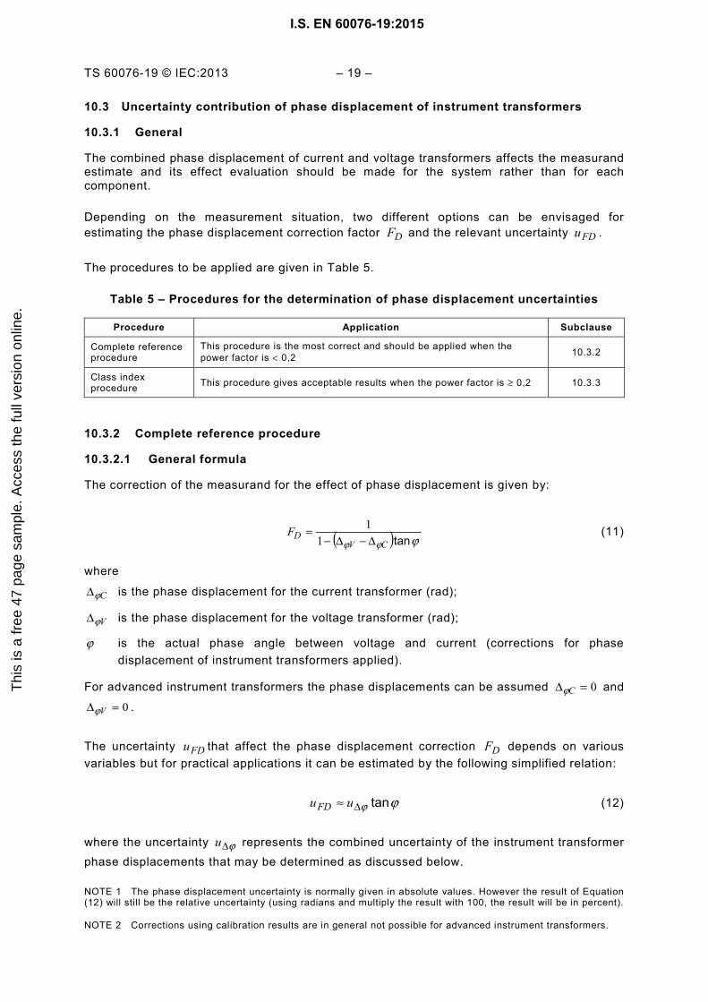
Depending on the measurement situation, two different options can be envisaged for estimating the phase displacement correction factor DF and the relevant uncertainty FDu .
The procedures to be applied are given in Table 5.
Table 5 – Procedures for the determination of phase displacement uncertainties
Procedure Application Subclause
Complete reference procedure
This procedure is the most correct and should be applied when the power factor is < 0,2 10.3.2
Class index procedure This procedure gives acceptable results when the power factor is ≥ 0,2 10.3.3
10.3.2 Complete reference procedure
10.3.2.1 General formula
The correction of the measurand for the effect of phase displacement is given by:
( ) ϕϕϕ tanCVDF
∆−∆−=
11 (11)
where
Cϕ∆ is the phase displacement for the current transformer (rad);
Vϕ∆ is the phase displacement for the voltage transformer (rad);
ϕ is the actual phase angle between voltage and current (corrections for phase displacement of instrument transformers applied).
For advanced instrument transformers the phase displacements can be assumed 0=∆ Cϕ and
0=∆ Vϕ .
The uncertainty FDu that affect the phase displacement correction DF depends on various variables but for practical applications it can be estimated by the following simplified relation:
ϕϕ tan∆≈ uuFD (12)
where the uncertainty ϕ∆u represents the combined uncertainty of the instrument transformer phase displacements that may be determined as discussed below.
NOTE 1 The phase displacement uncertainty is normally given in absolute values. However the result of Equation (12) will still be the relative uncertainty (using radians and multiply the result with 100, the result will be in percent).
NOTE 2 Corrections using calibration results are in general not possible for advanced instrument transformers.
I.S. EN 60076-19:2015T
his
is a
free
47
page
sam
ple.
Acc
ess
the
full
vers
ion
onlin
e.

– 20 – TS 60076-19 © IEC:2013
10.3.2.2 Uncertainty of conventional instrument transformers
The uncertainty is given by the following relation:
22CV uuu ϕϕϕ ∆∆∆ += (13)
where Cu ϕ∆ and Vu ϕ∆ are the standard uncertainties reported in the calibration report.
If the interpolation procedure is applied for determining the contribution of voltage and current transformers to the phase displacement and the corresponding uncertainties cannot be disregarded, it should be composed with the uncertainties determined as above:
2CΔ
2CintΔ
2VΔ
2VintΔΔ uuuuu ϕϕϕϕϕ +++= (14)
where the uncertainties intu are the standard uncertainties attributable to the interpolations. Determination of these phase displacements is discussed below.
This uncertainty are to be estimated, and can, in lieu of other evaluations, be assumed to be 1/3 of that applied interpolation correction.
In the case that the calibration certificate states the accuracy without information on the coverage factor, the corresponding standard uncertainty can be assumed equal to that accuracy divided by 3 (rectangular distribution of probability).
10.3.2.3 Uncertainty of advanced instrument transformers
For evaluating the phase displacement uncertainty it is sufficient to consider the accuracy specification and the accuracy of the calibration:
3
22 speccalC
uuu +=∆ϕ and
3
22 speccalV
uuu +=∆ϕ (15)
where
calu is the standard uncertainty obtained dividing by the coverage factor the expanded uncertainty for phase displacement given in a calibration certificate. If the coverage factor is not given explicitly, it is common procedure to assume a rectangular distribution and to divide by 3 ;
specu is the maximum phase displacement defined for the accuracy specification of the instrument transformer.
10.3.3 Class index procedure
No correction is applied to the measured power for phase displacement and therefore 1≈DF .
For conventional instrument transformers, the phase displacement uncertainty may be estimated from the maximum value the term DF could assume for the range of values of ϕtan expected to occur and supposing a rectangular distribution of the probability:
I.S. EN 60076-19:2015T
his
is a
free
47
page
sam
ple.
Acc
ess
the
full
vers
ion
onlin
e.
TS 60076-19 © IEC:2013 – 21 –
( ) ( ) ϕϕϕ tanCVDFD Fu
∆−∆−−=−=
111
311
31
(16)
where
Cϕ∆ is the negative class limit (expressed in radiant) for the current transformer phase displacement;
Vϕ∆ is the positive class limit (expressed in radiant) for the voltage transformer phase displacement.
For advanced instrument transformers, the rules given for the complete reference procedure apply (see 10.3.2).
10.4 Voltage and current measurements
The measurements should be performed by means of digital instruments. The accuracy of the results of each reading, expressed in percentage, is generally given by a formula of the following type:
rangecreadingba xx += (17)
where b and c are coefficients related to the accuracy specification of the instrument.
NOTE 1 In some manuals a third term referred to the offset is also indicated.
NOTE 2 The formula for the accuracy evaluation can differ from the one given above, the instrument manuals give the necessary information.
As the uncertainty is normally thought to have a rectangular distribution, the relative standard uncertainty is given by the following relations:
3
auUM = and 3
auIM = (18)
respectively for voltage and current measurements.
When in the manual of the instrument the uncertainty is directly given. Attention should be paid to the used coverage factor.
10.5 Power meter
The accuracy of a power measurement performed by means of a power analyzer depends on the errors related to the voltage and current channels, the power factor of the measurand and the instrument reading offset.
As various criteria can be followed for determining the power measurement uncertainty, it is recommended to make always reference to the power analyzer specification and relevant calibration reports.
For power analyzer of good quality, the errors due to the instrument itself can be normally disregarded so that the estimate of the uncertainty can be made through the so called error limits (range characterized by positive and negative values) that the instrument should never exceed in normal range of use and considering rectangular the distribution of the error probability.
I.S. EN 60076-19:2015T
his
is a
free
47
page
sam
ple.
Acc
ess
the
full
vers
ion
onlin
e.
– 22 – TS 60076-19 © IEC:2013
In some cases, the power uncertainty can be determined estimating separately the different contributions (voltage and current channels, power factor and offset) and then by combining them.
The standard uncertainty of each term can be obtained dividing for 3 the error limits mentioned above. If the single contributions can be considered not correlated, the total standard uncertainty may be obtained by a relation of this type:
2222offIVPW uuuuu +++= ϕ (19)
where
Vu is the contribution related to the voltage channel;
Iu is the contribution related to the current channel (including the contribution of the eventual shunt);
ϕu is the contribution related to the circuit power factor and to the instrument phase displacement;
offu is the contribution related to the offset.
Some instrument specifications report curves (or tables) that give the error limits as a function of the circuit power factor.
Such curves (or tables) can in general be regarded as representative of the maximum error. Assuming a rectangular distribution, the standard uncertainty can be estimated as this maximum error divided by 3 .
As such curves (or tables) are normally referred to the rated ranges of voltage and current channels, for measurements performed far from these reference conditions, it could be necessary to multiply the obtained value by the ratio:
UI
IU NN (20)
where NU and NI are the ranges of the voltage and current channels and U and I the actual readings.
Some instrument specifications allow to determine the uncertainty directly, but in these cases attention should be paid to the coverage factor used to indicate it.
10.6 Correction to sinusoidal waveform
An approximate correction for the value of the no-load loss due to distortion given in IEC 60076-1 is based on the true r.m.s. voltage rmsU and to the mean value of the rectified voltage avgU .
Firm background for asserting the uncertainty of the influence of voltage distortion on the value of the no load losses is not available, so that in the absence of other evidence, it is recommended to assign to the no-load loss an uncertainty:
I.S. EN 60076-19:2015T
his
is a
free
47
page
sam
ple.
Acc
ess
the
full
vers
ion
onlin
e.
TS 60076-19 © IEC:2013 – 23 –
avg
rmsavgwf U
UUu
4−
= (21)
When the indications uncertainty of the voltmeters responsive of the r.m.s. and mean voltages are equal within 3 %, the uncertainty on the correction to sinusoidal waveform may be disregarded.
10.7 Winding temperature at load loss measurement
The temperature of the windings during the load loss measurement is important for subsequent corrections of the results to reference temperature.
The winding temperature can either be directly measured by resistance variations or be estimated from the measurements of other quantities, before the loss measurement.
In both cases a suitable estimate of the uncertainty of the winding temperature is needed. Methods to derive this uncertainty are given below. In general, uncertainties are expected to be in the range of 1 K to 2 K.
The method based on the measurement of the winding resistances is justified for very large transformers and when the windings are presumed not to be in steady state conditions.
For small transformers, determination of winding temperature by measurement of winding resistance is often not justified. In cases where many identical transformers are tested, it can be satisfactory to perform an investigation on one unit as a special test, and use the result for all transformers of a batch.
When for large power liquid-immersed transformers the winding temperature is estimated through the liquid temperature, the same rules prescribed by IEC 60076-2 for the determination of the liquid average temperature during the temperature rise test can be applied.
When optical fibre thermal sensors are provided at the top of the windings for the measurement of the hot-spot temperatures, the average of their indications could be used instead of the liquid pocket temperature.
For liquid-immersed distribution transformers, where the height of the winding rarely exceed 1,5 m, it will be sufficient to consider only the temperature of the liquid in the pocket.
For dry type transformers, the average winding temperature can be determined by the average of the indications of thermal sensors located inside the axial cooling channels. Reference temperature determined through the measurement of the liquid temperature is applicable only if the winding can be considered to be in steady state condition during the test. The winding can be assumed to be in steady state condition if its temperature does not change by more than 1 K. This can be often achieved by keeping the time current application short in comparison with the winding thermal time constant.
10.8 Winding resistance measurement
The winding resistance is usually measured using the volt-ampere method and the uncertainty attributable to the instrument can be expressed with the following relation:
2221 SHUIMUMR uuuu ++= (22)
I.S. EN 60076-19:2015T
his
is a
free
47
page
sam
ple.
Acc
ess
the
full
vers
ion
onlin
e.
– 24 – TS 60076-19 © IEC:2013
where
uMu is the uncertainty in voltage measurement;
UIMu is the uncertainty in measurement of shunt voltage; and
SHu is the uncertainty of the shunt resistance.
NOTE It is assumed that sufficient time has elapsed to ensure that any transient phenomena incepted at measuring circuit closing have disappeared and stable readings are obtained.
To estimate the uncertainties, for voltage and current measurements, the same procedures indicated in sub-clause 10.4 should be applied.
For the current shunt it is normally sufficient to estimate the uncertainty from the class index disregarding the systematic deviation, that is:
3
2class
shuu = (23)
If the resistance measurement is performed by an integrated instrument, the uncertainty should be that given in the manufacturer specification and confirmed by calibration.
The uncertainty of the equivalent resistance obtained reporting the values at the supplied winding for the load loss measurement, may be obtained combining the absolute uncertainty of the single winding resistances.
The value of the resistance is also affected by the uncertainty contribution of the temperature at which the measurement is carried out, as explained under 10.7.
I.S. EN 60076-19:2015T
his
is a
free
47
page
sam
ple.
Acc
ess
the
full
vers
ion
onlin
e.

TS 60076-19 © IEC:2013 – 25 –
Annex A (informative)
Example of load loss uncertainty evaluation
for a large power transformer
A.1 General
The following example refers to the evaluation of the uncertainty that can affect the measurement of load loss of a large power transformer performed at ambient temperature and using the three wattmeter method (three separated single-phase measurements).
The example was derived from the real measurement performed on a large oil-immersed three-phase power transformer.
In the example, the determination of the uncertainties was limited to only one of the phases.
The following simplifications have been introduced:
– measurand not modified by the test conditions (invariant) so that only the uncertainties introduced by the method and instrumentation used and by the winding temperature estimate are considered;
– sinusoidal and symmetrical current system; – constant rated frequency.
It can be noted that the effects of the two last variables are normally on secondary order on the uncertainty estimate when the test complies with IEC 60076-1.
In the text reference is made to the clauses of the main document.
A.2 Transformer ratings
The main transformer characteristics are reported in Table A.1.
Table A.1 – Transformer ratings
Number of phase 3
Rated frequency 50 Hz
Rated power 90 MVA
Rated voltages 240/15 kV
Rated currents 216,5 / 3 464 A
Short-circuit impedance 12,5 %
Load loss at 75 °C (guarantee value) 270 kW
Winding connections star/delta
A.3 Measuring method and instrumentation used
The transformer was supplied from the high voltage winding with the low voltage winding short-circuited.
I.S. EN 60076-19:2015T
his
is a
free
47
page
sam
ple.
Acc
ess
the
full
vers
ion
onlin
e.

– 26 – TS 60076-19 © IEC:2013
Three independent electric measuring systems were provided for the measurement of the loss.
The following instrumentation was used:
– current transformers: rated ratio 300/5 A, accuracy class 0,1; – voltage transformer: rated ratio 20 000/100 V, accuracy class 0,1; – power analyzer by which active power, current and voltage were measured; – six (6) temperature sensors applied to the transformer tank to estimate the average
winding temperature.
(Other devices can be used to scale down voltage and current, such as capacitive voltage dividers and advanced current transformers).
The resistance measurements were carried out on both the windings at ambient temperature with the volt-ampere method according to 10.8 and then referred to the winding supplied for the load loss measurement.
A.4 Model function of the measurand and deviation correction (see 7.2)
A.4.1 Model function
The model function for load loss referred to rated current is given by:
( )2
tan1100
1
1100
1
×
−−×
+×
+=
MCN
N
CV
WV
VNC
CN2 IkI
ΔΔP
ε k εkPϕϕϕ
A.4.2 Correction of known systematic deviations
The known systematic deviations of the power meter have been assumed to be negligible, as well as for ratio of current and voltage transformers. As rated current was used at the test correction for current is not needed. The phase angle ϕ of the loss power is obtained from:
CVMM
WCVM UI
Pϕϕϕϕϕϕ ∆+∆−
=∆+∆−= arccos
The remaining corrective term, is the following equation:
( ) ϕϕϕ tan×∆+∆−=
CVCK
11
The corrected power is therefore:
CWVNCN KPkkP x x x =2
A.5 Results of the measurements
A.5.1 Load loss measurements
On one of the phases, the readings of the power analyzer are reported in Table A.2.
I.S. EN 60076-19:2015T
his
is a
free
47
page
sam
ple.
Acc
ess
the
full
vers
ion
onlin
e.
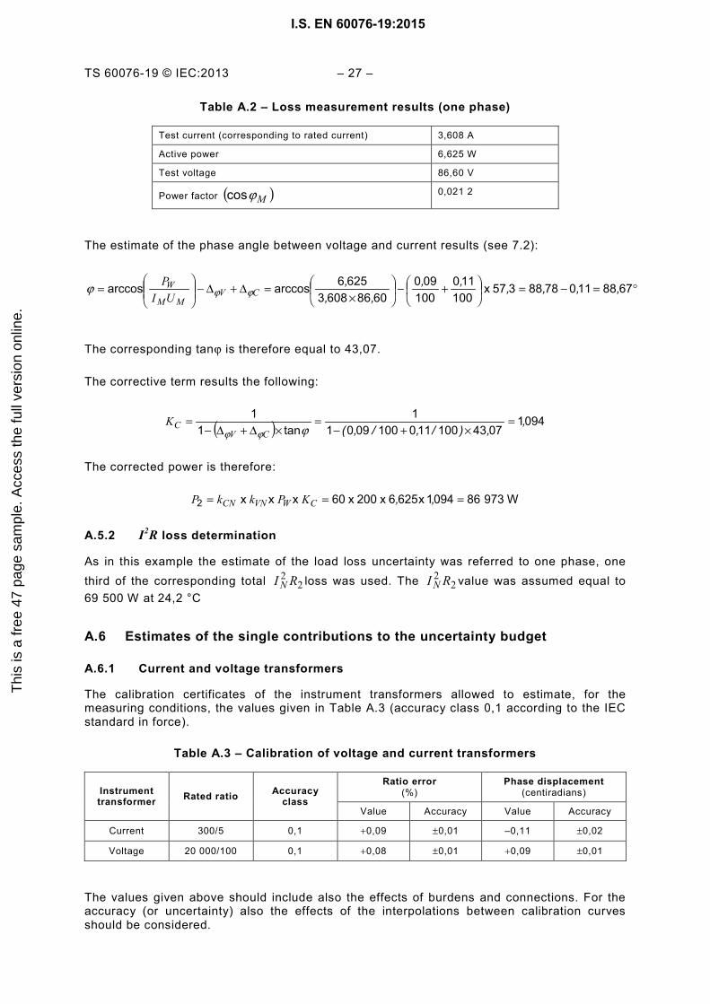
TS 60076-19 © IEC:2013 – 27 –
Table A.2 – Loss measurement results (one phase)
Test current (corresponding to rated current) 3,608 A
Active power 6,625 W
Test voltage 86,60 V
Power factor ( )Mϕcos 0,021 2
The estimate of the phase angle between voltage and current results (see 7.2):
°=−=
+−
×=∆+∆−
= 67881107888357 x
100110
100090
608660836256arccosarccos ,,,,,,
,,,
CVMM
WUI
Pϕϕϕ
The corresponding tanϕ is therefore equal to 43,07.
The corrective term results the following:
( ) 094107431001101000901
1tan1
1 ,,)/,/,(
=×+−
=×∆+∆−
=ϕϕϕ CV
CK
The corrected power is therefore:
W973860941x 6256x 200x 60x x x 2 === ,,CWVNCN KPkkP
A.5.2 I2R loss determination
As in this example the estimate of the load loss uncertainty was referred to one phase, one third of the corresponding total 2
2 RI N loss was used. The 22 RI N value was assumed equal to
69 500 W at 24,2 °C
A.6 Estimates of the single contributions to the uncertainty budget
A.6.1 Current and voltage transformers
The calibration certificates of the instrument transformers allowed to estimate, for the measuring conditions, the values given in Table A.3 (accuracy class 0,1 according to the IEC standard in force).
Table A.3 – Calibration of voltage and current transformers
Instrument transformer Rated ratio Accuracy
class
Ratio error (%)
Phase displacement (centiradians)
Value Accuracy Value Accuracy
Current 300/5 0,1 +0,09 ±0,01 –0,11 ±0,02
Voltage 20 000/100 0,1 +0,08 ±0,01 +0,09 ±0,01
The values given above should include also the effects of burdens and connections. For the accuracy (or uncertainty) also the effects of the interpolations between calibration curves should be considered.
I.S. EN 60076-19:2015T
his
is a
free
47
page
sam
ple.
Acc
ess
the
full
vers
ion
onlin
e.

– 28 – TS 60076-19 © IEC:2013
A.6.2 Instrument transformer ratio error uncertainties (see 10.2)
Because of the good accuracy classes of the used instrument transformers, the contribution of the ratio errors to the total uncertainty was of secondary order and therefore it was disregarded.
A.6.3 Instrument transformer phase displacement uncertainties (see 10.3)
The uncertainty introduced by the instrument transformers are to be estimated starting from the accuracy ( FVa and FCa ) of the phase displacements declared in the calibration certificates.
For the example, using the values indicated in Table A.3, the absolute standard uncertainties on the phase displacements is to be evaluated as follow:
crad 501103020
3,, === FV
FVau
crad 700503
01003
,, === FCFC
au
NOTE In some cases, in the calibration certificates the uncertainty is directly indicated with a given confidence level and therefore the standard uncertainties can be directly obtained from these data.
A.6.4 Power analyzer uncertainties (see 10.5)
According to the used instrument manual, the accuracy on power measurement is obtained by the combination of a number of terms:
++++±= e
PIUd
IUIUc
IIb
UUaF
X
NN
NN
XX
N
X
N
X x x x
(other combinations can be proposed according to the manual of the instrument used and to its accuracy class)
For the measurement at which the example refers to (very low power factor) the dominant term was the fourth that depends on the power factor.
The accuracy determined in accordance with the above relation resulted of ±0,91 %.
The corresponding standard uncertainty estimated in accordance with the rules given in 10.4 was:
%5303910 ,, ==PWu
For the current measurement, the same instrument assured an accuracy of ±0,21 % at which the following standard uncertainty corresponds:
%1203210 ,, ==IMu
For the voltage measurement, the instrument assured an accuracy of ±0,18 % at which the following standard uncertainty correspond:
I.S. EN 60076-19:2015T
his
is a
free
47
page
sam
ple.
Acc
ess
the
full
vers
ion
onlin
e.
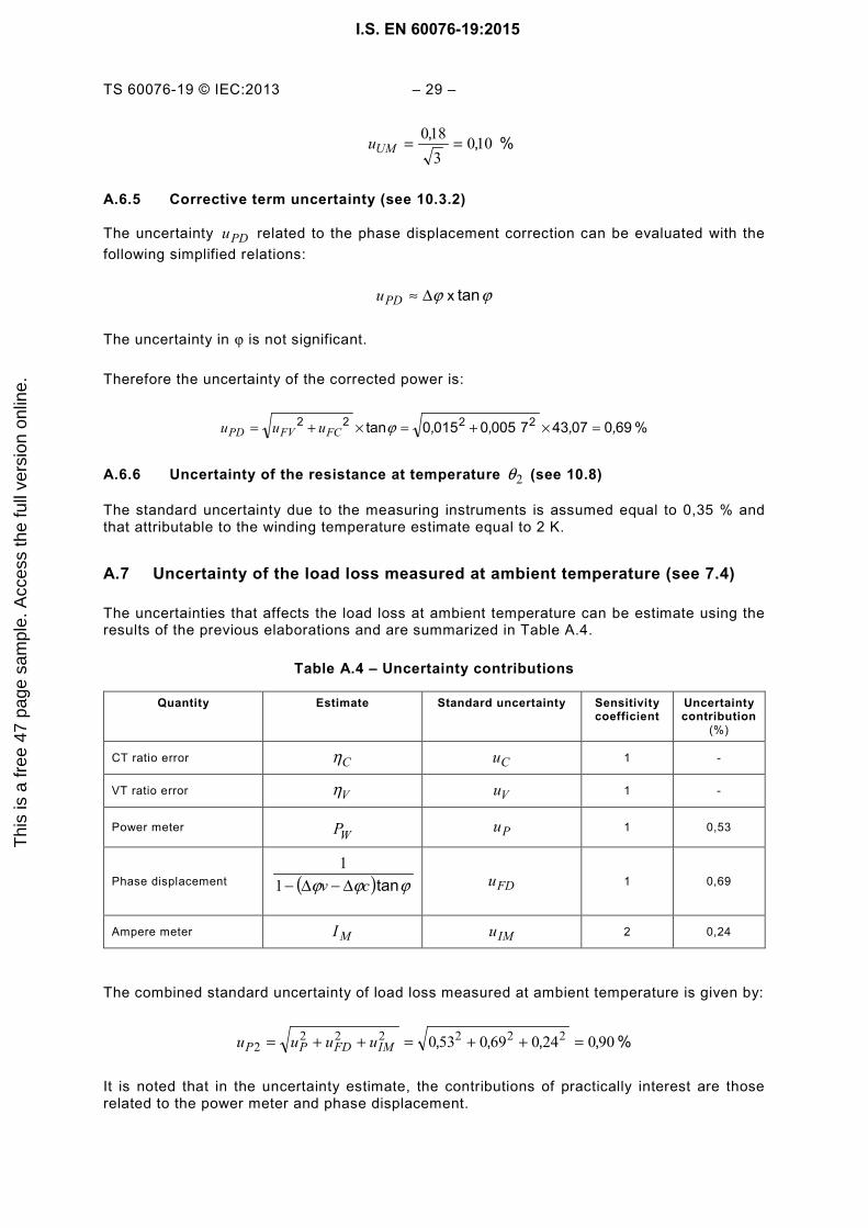
TS 60076-19 © IEC:2013 – 29 –
% ,, 1003180 ==UMu
A.6.5 Corrective term uncertainty (see 10.3.2)
The uncertainty PDu related to the phase displacement correction can be evaluated with the following simplified relations:
ϕϕ tan x∆≈PDu
The uncertainty in ϕ is not significant.
Therefore the uncertainty of the corrected power is:
% 6900743700500150tan 2222 ,,,, =×+=×+= ϕFCFVPD uuu
A.6.6 Uncertainty of the resistance at temperature 2θ (see 10.8)
The standard uncertainty due to the measuring instruments is assumed equal to 0,35 % and that attributable to the winding temperature estimate equal to 2 K.
A.7 Uncertainty of the load loss measured at ambient temperature (see 7.4)
The uncertainties that affects the load loss at ambient temperature can be estimate using the results of the previous elaborations and are summarized in Table A.4.
Table A.4 – Uncertainty contributions
Quantity Estimate Standard uncertainty Sensitivity coefficient
Uncertainty contribution
(%)
CT ratio error Cη Cu 1 -
VT ratio error Vη Vu 1 -
Power meter WP Pu 1 0,53
Phase displacement ( ) ϕϕϕ tancv ∆−∆−11
FDu 1 0,69
Ampere meter MI IMu 2 0,24
The combined standard uncertainty of load loss measured at ambient temperature is given by:
% ,,,, 900240690530 2222222 =++=++= IMFDPP uuuu
It is noted that in the uncertainty estimate, the contributions of practically interest are those related to the power meter and phase displacement.
I.S. EN 60076-19:2015T
his
is a
free
47
page
sam
ple.
Acc
ess
the
full
vers
ion
onlin
e.

– 30 – TS 60076-19 © IEC:2013
A.8 Expanded uncertainty of the measured load loss (see 7.4)
The expanded relative uncertainty is:
% ,, x 80190022 22 === PP uU
Passing to the absolute expanded uncertainty:
kW 5719786100
801100 2
22 ,,, === PUU P
P
On the test report, the estimated result of the measurement should be given with the indication of the expanded uncertainty.
If the uncertainty is given in relative value, the load loss at ambient temperature 24,2 °C are to be expressed as follows:
% 801kW 9786 ,, ±
Alternatively, if the uncertainty is given in absolute value:
kW 571kW 9786 ,, ±
The result shall be also completed with the indication of the coverage factor that for the example made was k = 2 (confidence level of about 95 %).
A.9 Uncertainty for reported load loss at reference temperature (see 7.5)
For estimating the total load loss at the reference temperature, the loss powers and their associated uncertainty contributions are to be expressed in absolute quantities.
The additional loss at ambient temperature are given by:
W 47017500699708622
22 =−=×−= RIP NaP
The absolute uncertainty of the measured loss and RI N2 loss are obtained as follows:
W78397086100
900100 2
22 === ,Puu P
P and W23050069100
350100 2
2 === ,RIuu NR
R
The absolute uncertainty of the additional loss at temperature 2θ is given by:
W) ( x 816230783 22222
2222 =+=+= RNPPa uRIuu
The sensitivity factors for copper conductors, reference temperature C °= 75rθ and ambient temperature C , °= 2242θ can be assumed:
1912
,=++
θθ
tt r 8402 ,=
++
rtt
θθ
22
22
22 60040 RI
ttRI N
rN ,
)(≅
++θθ
I.S. EN 60076-19:2015T
his
is a
free
47
page
sam
ple.
Acc
ess
the
full
vers
ion
onlin
e.

TS 60076-19 © IEC:2013 – 31 –
The reported loss at the reference temperature is given by:
W380976751470582840191 222 =+=+= aNLL PRIP ,,
The various contributions to the absolute uncertainty are calculated according to Table 4:
W289100350 x 50069 x 191222
2==
++= /,,RN
rRL uRI
ttu
θθ
W68522 ==
++= 816,8 x 40Pa
rPaL u
ttu
θθ
( ) W32050069 x 600402
22
2==
++= ,θθθθ uRI
ttu rN
rL
The combined absolute standard uncertainty is given by:
W80932068528960040840191 222222
222
222
2 =++=++= ),(),(),( θuRIuuRIu NPaRNLL
The expanded absolute uncertainty is obtained as:
kW ,, x 62181022 === LLLL uU
which corresponds to a coverage probability of approximately 95 %.
The relative standard uncertainty is then:
% 83010038097
809100 ,===LL
LLLL P
uu
and the expanded relative uncertainty:
% 6618302 2 ,, =×== LLLL uU
which corresponds to a level of confidence of approximately 95 %.
The results obtained are a little greater than the ones estimated for the load loss at ambient temperature 2θ .
A.10 Presentation of the results
On the test report, the estimated result of the load loss measurement should be given with the indication of the expanded uncertainty.
If the uncertainty is given in relative value, the load loss at reference temperature 75 °C are to be expressed as follows:
% 661kW 497 ,, ±
I.S. EN 60076-19:2015T
his
is a
free
47
page
sam
ple.
Acc
ess
the
full
vers
ion
onlin
e.

– 32 – TS 60076-19 © IEC:2013
Alternatively, if the uncertainty is given in absolute value:
kW 621kW 497 ,, ±
The text shall be also completed with the indication of the coverage factor that for the example made was k = 2 (confidence level of about 95 %).
I.S. EN 60076-19:2015T
his
is a
free
47
page
sam
ple.
Acc
ess
the
full
vers
ion
onlin
e.
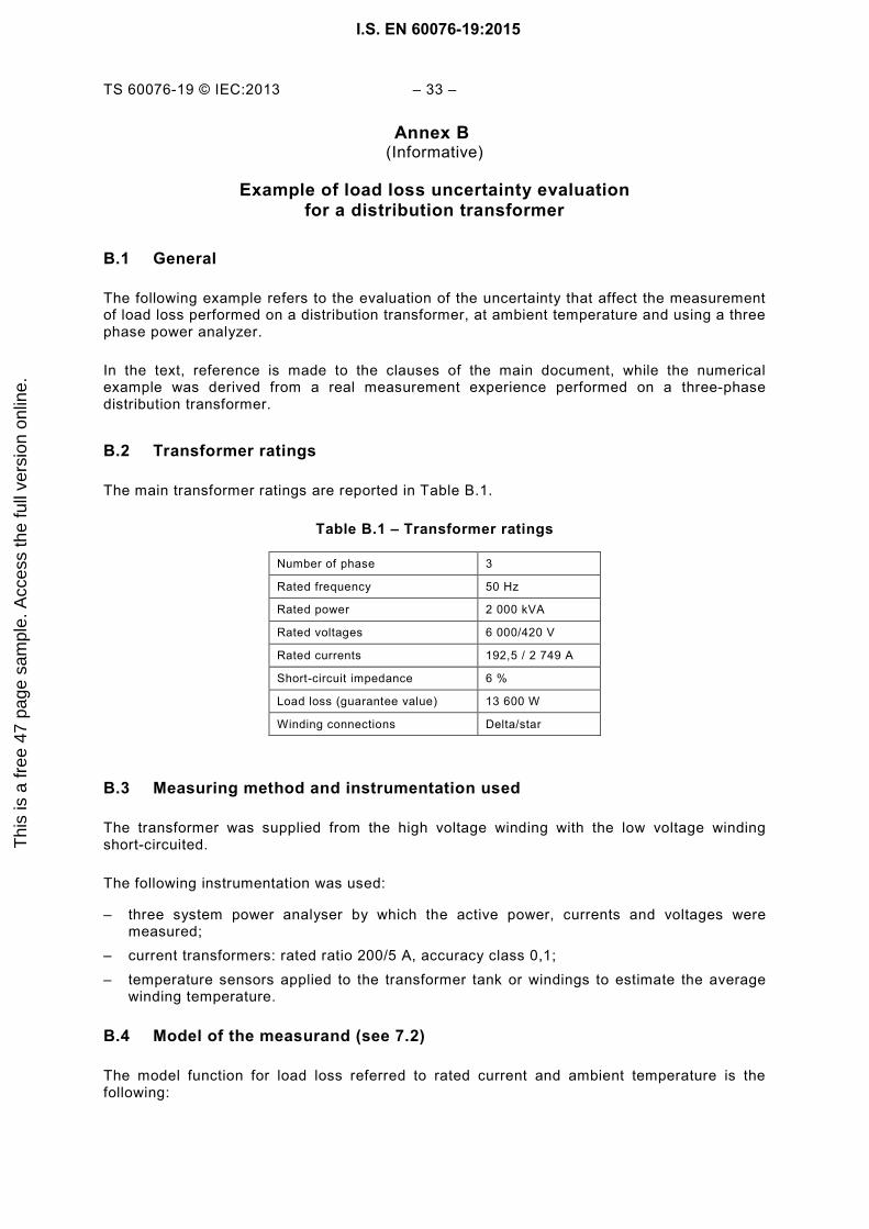
TS 60076-19 © IEC:2013 – 33 –
Annex B (Informative)
Example of load loss uncertainty evaluation
for a distribution transformer
B.1 General
The following example refers to the evaluation of the uncertainty that affect the measurement of load loss performed on a distribution transformer, at ambient temperature and using a three phase power analyzer.
In the text, reference is made to the clauses of the main document, while the numerical example was derived from a real measurement experience performed on a three-phase distribution transformer.
B.2 Transformer ratings
The main transformer ratings are reported in Table B.1.
Table B.1 – Transformer ratings
Number of phase 3
Rated frequency 50 Hz
Rated power 2 000 kVA
Rated voltages 6 000/420 V
Rated currents 192,5 / 2 749 A
Short-circuit impedance 6 %
Load loss (guarantee value) 13 600 W
Winding connections Delta/star
B.3 Measuring method and instrumentation used
The transformer was supplied from the high voltage winding with the low voltage winding short-circuited.
The following instrumentation was used:
– three system power analyser by which the active power, currents and voltages were measured;
– current transformers: rated ratio 200/5 A, accuracy class 0,1; – temperature sensors applied to the transformer tank or windings to estimate the average
winding temperature.
B.4 Model of the measurand (see 7.2)
The model function for load loss referred to rated current and ambient temperature is the following:
I.S. EN 60076-19:2015T
his
is a
free
47
page
sam
ple.
Acc
ess
the
full
vers
ion
onlin
e.

– 34 – TS 60076-19 © IEC:2013
2
x1
x100
12
×∆+
+=
MCN
N
C
WCCN Ik
IPkPϕϕ
εtan
The known systematic deviations of the power meter have been assumed to be negligible. The phase angle ϕ of the loss power is obtained from:
CMM
WCM UI
P ϕϕϕϕ ∆+
=∆+= arccos
The corrective term for phase displacement is given by:
ϕϕ tanC∆+11
When the ratio error of the current transformers and its uncertainties are very low, the model may be reduced as follows:
2
2 xtan1
x
×∆+
=MCN
N
C
WCN Ik
IPkPϕϕ
B.5 Results of the measurements
On the examined transformers, the following measuring results at ambient temperature were obtained from the power analyzer are reported in Table B.2.
Table B.2 – Measured quantities
Test current (corresponding to rated current) 4,812 A
Power meter indication at rated current ( WP ) 337,5 W
Test voltage 365,0 V
Power factor ( Mϕcos ): 0,111
Measured active power at rated current: 13 500 W
The indications of the three power systems were of the same order.
The estimate of the phase angle between voltage and current results (see 7.2):
°=+=+
××
=∆+
×
= 658302063833571000350
0365381245337arccos ,,,,,
,,,arccos C
MM
WUI
P ϕϕ
The corresponding tanϕ is therefore equal to 8,99.
The corrective term results the following:
997099810003501
1tan1
1 ,,/,
=×+
=∆+
=ϕϕC
CK
The corrected power is therefore:
I.S. EN 60076-19:2015T
his
is a
free
47
page
sam
ple.
Acc
ess
the
full
vers
ion
onlin
e.

TS 60076-19 © IEC:2013 – 35 –
W460139970 5337 40 2 =××=××= ,,CWCN KPkP
B.6 Estimate of the single contributions to the uncertainty formation
B.6.1 General
Following the indication given in the main document, the single contributions to the formation of the uncertainty that affected the measurand are discussed.
B.6.2 Power analyzer (see 10.5)
According to the instrument manual, the accuracy of the measured power is given by the combination of a number of terms. For the cases under consideration the accuracy resulted of ±0,57 %.
The corresponding standard uncertainty estimated is:
% 33,0357,0 ==Wu
For the current measurement, the same instrument assured an accuracy of ±0,42 % at which the following standard uncertainty corresponds:
% 24,0342,0 ==Au
For the voltage measurement, the instrument assured an accuracy of ±0,25 % at which the following standard uncertainty correspond:
% 14,0325,0 ==Uu
B.6.3 Current transformers (see 10.3)
For the measurement, current transformers of accuracy class 0,1 according to the IEC standard in force) were used.
For the type of transformer under test the values of the ratio error and displacement error given by the calibration certificate can be considered, as indicated in Table B.3.
Table B.3 – Calibration of the current transformers
Rated ratio Accuracy class
Ratio error (%)
Phase displacement (centiradians)
ε cu Value cϕ∆
200/5 0,1 0,0 0,01 + 0,035 0,01
NOTE The errors reported in the table are those measured including burden and connections corresponding to the instrument used.
I.S. EN 60076-19:2015T
his
is a
free
47
page
sam
ple.
Acc
ess
the
full
vers
ion
onlin
e.

– 36 – TS 60076-19 © IEC:2013
B.6.4 Corrective term uncertainty (see 10.3.2)
The corrective term uncertainty is given by.
% 31,099,8 035,0tan ==∆= x x ϕϕCFDu
B.7 Uncertainty of the load loss measured at ambient temperature (see 7.4)
The uncertainty affecting the load loss at ambient temperature can be estimate using the results of the previous elaborations as summarized in Table B.4.
Table B.4 – Uncertainty contribution
Quantity Estimate Standard uncertainty Sensitivity coefficient
Uncertainty contribution
Power meter WP Pu 1 0,33 %
Phase displacement ϕϕ tanC∆−1
1 FDU 1 0,31 %
Ampere meter MI IMu 2 0,48 %
The combined uncertainty of load loss measured at ambient temperature is given by:
% ,,,, 660480310330 222222 =++=++= IFDPLL uuuu
B.8 Expanded uncertainty of the load loss (see 7.4)
The relative expanded uncertainty is:
% ,, x 32166022 === LLLL uU
Passing to the absolute expanded uncertainty:
kW 180513100
321100
,,, === PUU PLL
On the test report, the estimated result of the measurement should be given with the indication of the expanded uncertainty.
If the uncertainty is expressed in relative value, the load loss at ambient temperature is to be declared as follows:
%321kW513 , , ±
Alternatively, if the uncertainty is given in absolute value:
kW180kW513 , ,±
The result shall be also completed with the indication of the coverage factor that for the example made was k = 2 (confidence level of about 95 %).
I.S. EN 60076-19:2015T
his
is a
free
47
page
sam
ple.
Acc
ess
the
full
vers
ion
onlin
e.

TS 60076-19 © IEC:2013 – 37 –
Bibliography
IEC 60076-8, Power transformers – Part 8: Application guide
IEC 61869-1, Instrument transformers – Part 1: General requirements
IEC 61869-2, Instrument transformers – Part 2: Additional requirements for current transformers
IEC 61869-3, Instrument transformers – Part 3: Additional requirements for inductive voltage transformers
IEC 61869-7, Instrument transformers – Part 7: Electronic voltage transformers 1
IEC 61869-8, Instrument transformers – Part 9: Electronic current transformers 1
ISO/IEC 17025:2005, General requirements for the competence of testing and calibration laboratories
ISO/IEC Guide 98-3:2008, Uncertainty of measurement – Part 3: Guide to the expression of uncertainty in measurement (GUM:1995)
IEEE C57.123-2002, IEEE Guide for Transformer Loss Measurement
_____________
___________ 1 Under consideration.
I.S. EN 60076-19:2015T
his
is a
free
47
page
sam
ple.
Acc
ess
the
full
vers
ion
onlin
e.

This is a free preview. Purchase the entire publication at the link below:
Looking for additional Standards? Visit SAI Global Infostore
Learn about LexConnect, All Jurisdictions, Standards referenced in Australian legislation
Need to speak with a Customer Service Representative - Contact Us
Thi
s is
a fr
ee 4
7 pa
ge s
ampl
e. A
cces
s th
e fu
ll ve
rsio
n on
line.
I.S. EN 60076-19 : 2015 : EN : COMBINED PDF