Embed Size (px)
Citation preview

/'"
MEASUREMENT OF STREAMING POTENTIALS')'L
DESCRIPTION OF THE APPARATUSThe apparatus is described under the following three
sections: a) streaming potential cell; b) automatedgas flow system and; c) electrical circuit.a) Streaming potential cell :
The cell consists of two parts: the cell assemblyand the electrode assembly. A schematic diagram isgiven in Figure 1. The former consists of two 500 ccpyrex glass bulbs (A) joined to p,8ch end of a semi-circular sample tube (B) of 1.3 cm inner diameter and9 cm length. The remicircular part of a second cell,made for use when only limited amounts of mineral isavailable, has an inside diameter of 0.8 cm and a lengthof 7 cm. The bulbs are provided with No. 25 "0" ringjoints, one inlet for gas, and another for the introductionof pH electrodes or thermometers. The "0" ring jointsprovide a seat for the electrode assembly.
The use of streaming potential technique in studying theelectrokinetic properties of mineral-water systems is described inderail. An automated apparatus that houses a single piecestreaming cell and that is capable of continuous operation overlong periods of time as well as operation at higber-than-ambient temperatures, is described, The advantages of thenew system peraaking precise measurements and the variousprecautions and specific procedures to be adopted to obtainaccurate and reliable readings are stressed.
Adsorption of inorganic as well as organic specieson particles is often governed by the electrical properties
of their surfaces in solutions. The determinationof the electrical characteristics of the particle!solution interface and its change due to thepresence of various relevant chemicals is therefore of
major use for cstablishing mechanisms by which theyact. Of the various electrokinetic techniques that areavailable for determining parameters that are useful
measures of the electrical properties of the particle-solution interface, the most suitable for studying sieve-size pltrticles is the streaming potential technique. For
the measurement of streaming potential, most investiga-tors use a cell similar in principle to that described byFuerstena~( I', with either bright platinum or silver-silverchloride electrodes. Such conventional cells cannot besafely employed to conduct studies as a function oftemperature since they have many glass joints that are
prone to leakage, particularly under pressure, in thecourse of an experiment. Effect of temperature is a
variable coming into increasing usage in mineral process-ing operations'V. In addition, previous studies onsemi-soluble minerals such as calcite')'. apatite'.> andsparingly soluble minerals such as quartz'S,6) have
given evidence for significant chang~s in tbeir electro-
kinetic properties as a function of aging time. Such
changes are relevant to mineral processing operationswhere the crushed ore particles might not have reachedequilibruim with the water in contact. In order to studythe strf'aming potential precisely as a function of
concentlation of reagents, aging time and temperature,a new automated streaming potential apparatus wasdesigned and built. The description of the apparatus as
well as the most satisfactory procedures for accurate
measurements are provided in this paper.
SCIE..., I( «' CElL A/C ElB:T~ AS~''.'
Tbe electrode assembly consists of two perforatedplatinum discs of about 2.0 cm diameter and 0.25 cmthickness. They are welded on one side to a platinumguaze (80 mesh) aDd on the other side axially to a 16 cmlong thin platinum rod of 0.25 em diameter. Theelectrode length is further increased to 33cm, by weldinga thin tungsten rod of 0.3 cm diameter on to the platinum
.present Address: Te<;hnology Dept.. Metals Division. UnionCarbide Corporation, Niagara Falls, New York...Terrytown Technical Center. Union Carbide Corporation.
Tarrytown. New York.
26-2 (1977) 7Electroroem. Soc. India
P. Somasupdarajli - S. Ramachandran-, and R. D. Kulkarni--
School of Engineering and Applied Science, Columbia University, New York. N.Y. 210027, USA..
(Received and accepted Jan. 1977)

P\.,.P. Somasundarlpf. S. Ramachandran, and R. D. Kuliami Measurement of Streaming Potentials8
This reading is necessary to evaluate the plug resistanceaccurately at values of cell resistance that are too highfor the use of an impedance bridge for resistancemeasurements. The second ten-minutes timer is forcontrolling the recorder chart drive. Table I gives thetiming schedwle of the opcration of the solenoid valvesfor one complete cycle of streaming potential measure-ments. Table 2 gives an ac.:ount of the variousfunctions of the three solenoid valves. The above set-upis illustrated in Figures 1 and 2. The gas used for
pressurizing the bulbs is water-pumped nitrogen passedthrough plugs of calcium chloride and ascarite, and
wash bottles containing distilled water.
Time Schedule for the TimersTable
2-MIRute IO-Minute TimerTimer Recorder
2-way Decade I and 2 mls~alve register timers chart dr.
Time -MinuteTImer
3-wayvalve
4-wayvalvo
~
ofToff
on
off
off0
2
14
IS
2S
30
32
44
4S
~S
60
oft' onon00
00
off
0'
00 on
'0 00
00 00
off ,.
off t.
1 miD cyclerepeat
"..on
..
..
..
00
off
....
"..
rod. The electrode is fused to a 2.0 cm diameter and13 cm long glass tube (F) with 2 circular grooves on itto hold two "0" - rings. This tube along with the
electrode can be introduced into another glass tube(H) and be held in~ide this. with the help of the two"0" rings. The glau tube (HI is provided at one endwith a suitable "0" ring joint for connecting it to the cellassembly described earlier. The above arrangementensures free movement of electrodes inside the cell evenafter fixing the outer tube (H) in its position without anydisturbance of the pressure inside the system and with-out introducing any torque at the electrode-glass sealwhile preparing the mineral plug.
b) Gas Flow Systeaa :
The various steps in measuring the streamingpotential could be listed as under:
I) Pressurizing ODe of the bulbs of the cell - thi~ isthe starting point for streaming in one directionfor, say, 15 seconds.
II) Connecting the other bulb to the atmosphere.III) Connecting the pressurized bulb to the mano-
meter.
IV) Locking the pressure in the manometer just onesecond before depressurizing the first bulb torecord the streaming pressure.
V) Opening the first bulb also to the atmosphere.
VI) Repeating the above operations after, say, 15seconds with streaming in the opposite direction.
"on
""
".,
Thus one cycle or streaming potential readingi couldbe taken each minute. This is a.:hleved by the use orthree solenoid valves (one four-way valve, one three-wayvalve and one two-way valve all normally closed), thesebeing controlled by a one-minute five-cam timer. Aprovision is also made to eliminate the IS secondsinterval between the two streamings. This enablesinstantaneous reversal or streaming, which would beuseful during the conditioning of the mineral with thesolution in question in that, now there is continuousstreaming for several minutes, which gives not onlybetter conditioning efficiency but also better utilizationof time. Another main advantage is the elimination ofvarious experimental errors, introduced by manualoperation. In addition to the above, there is a set oftwo-minute one-cam timer and a ten-minllte two.camtimer in the system. The first is to introduce a resis-tance in parallel to the mineral plug every alternatestreamins cycle, so that the strcamin~ potential undersuch conditions could also be obtained automatically.
off
on
off
on
OD
OD
--
,-
-,--
"00
off
120 "180 "
2tO II
300 ..
300-r00 system off off
Table II. Functions of the sl,lenoiJ valvcs
Valve When "on" When "off"4-\\ ay pressurizes RHS bulb of pressurizes the LHS bulb
cell and opens the LHS and opens the RHS bulb tobulb to atmosphere atmosphere
'-Way pressurizes the system depressurizes and coonectsby opeoing the Nt the system to atmosphcroiolet valvo
2-Way connects the mercury locks the manometricrnanomekr to the pressurepressure system
c) Electrical System:The potential developed across the electrodes during
streaming is fed to a high impedence electrometer
(Keitheley 616 electrometer) tbruugh a po(ential divider.
(1911)26-2Electrochem. Soc. India
)\.-P Soma(undara~, S. Ramactlandra11, and R~ D. Kulkarni Measurement or StreamIng Potentials. 9
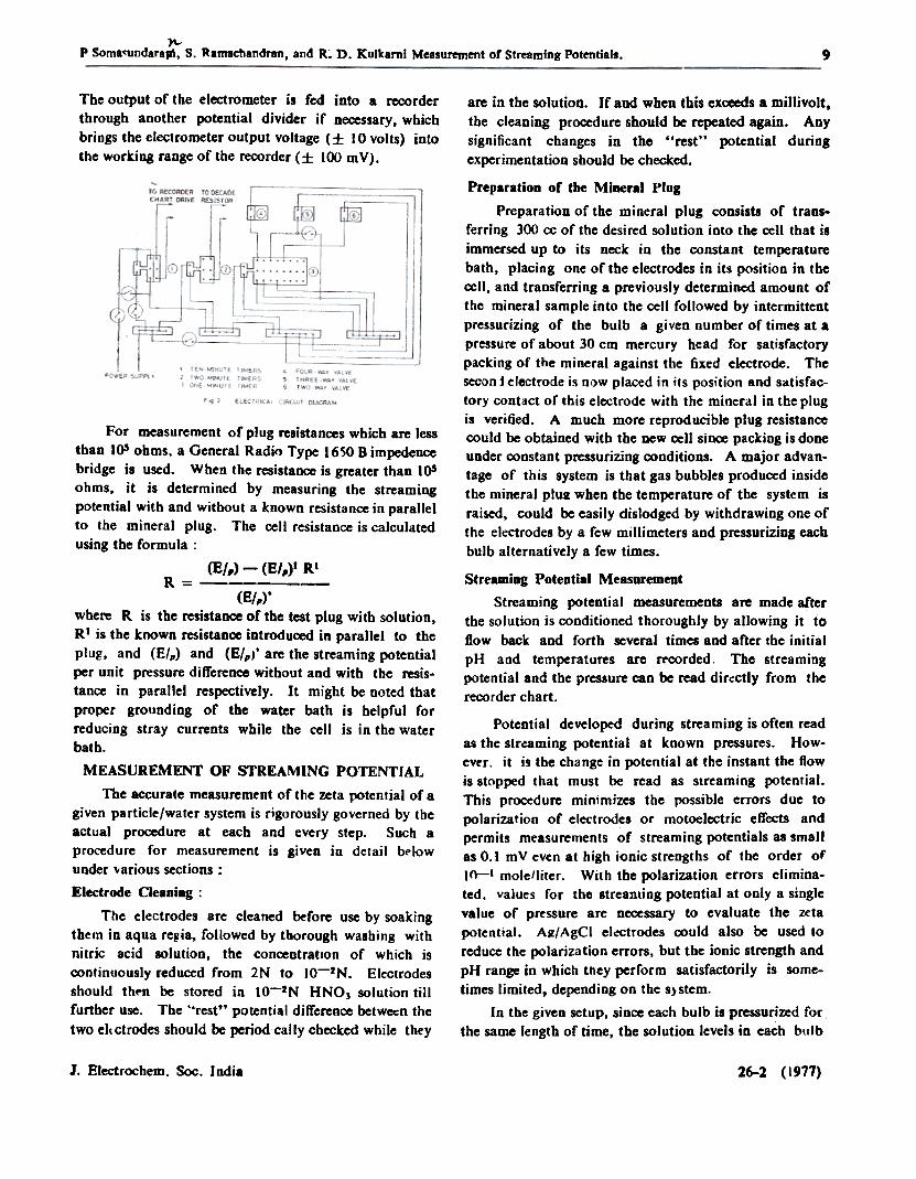
The output of the electrometer is fed into a recorderthrough another potential divider if ne<:essary, whichbrings the electrometer output voltage (.f: 10 volts) intothe working range of the recorder (.f: 100 mY).
are in the solution. If and when this exceeds a millivolt,the cleaning pr~ure should be repeated again. Anysignificant changes in the "rest" potential duringexperimentation should be checked.
For measurement of plug resistances which are lessthan 105 ohms. a General Radio Type 1650 B impedenccbridge is used. When tbe resistance is greater than 105ohms. it is determined by measuring the streamingpotential witb and without a known resistance in parallelto the mineral plug. The cell resistance is calculatedusing the formula:
(E/,) - (E/,)I RIR = (8/,).
whe~ R is the ~sistance of the test plug with solution,R I is the known resistan~ introduced in parallel to the
plug. and (8/,) and (E/,)' a~ the streaming potentialper unit pressure differen~ without and with the resis-tance in parallel respectively. It might be noted thatproper grounding of the water bath is helpful forreducing stray cur~nts while the cell is in the waterbath.
MEASUREMENT OF STREAMING POTENTIAL
The accurate measuremtnt of the zeta potential of agiven particle/water system is rigorously governed by theactual procedure at each and every step. Such aprocedure for measurement is given in detail bt'lowunder 'iarious sections:
Electrode Cleaning:
The electrodes are cleaned befo~ use by soakingthtm in aqua re~ia. followed by thorough washing withnitric acid solution, the concentration of which iscx>ntinuously reduced from 2N to IO-2N. Electrodesshould tht'n be stored in to-2N HNO) solution tillfurther use. The "rest" potential difference betwecn thetwo elcctrodes should be period'cally checked while they
Preparation of the Mineral Plug
Preparation of the mineral plug consists of trans-ferring 300 cc of the desired solution into the cell that isimmersed up to its neck in the constant temperaturebath, placing one of the electrodes in its position in tberei I, and transferring a previously determined amount ofthe mineral sample into the cell followed by intermittentpressurizing of the bulb a given number of times at apressure of about 30 cm mercury bead for satisfactorypacking of the mineral against the fixed electrode. Thesecon j electrode is now placed in ilS position and satisfac-tory contact of this electrode with the mineral in the plugis veri lied. A much more reproducible plug resistancecould be obtained with the new cell since packing is doneunder constant pressurizing conditions. A major advan-tage of this system is that gas bubbles produced insidethe mineral plUR when the temperature of the system israised, could be easily dislodged by withdrawing one ofthe electrodes by a few millimeters and pressurizing eachbulb alternatively a few times.
Streaming Potential Measurement
Streaming potential measurements are made afterthe solution is conditioned thoroughly by allowing it toflow back and forth several times and after the initialpH and temperatures are n-corded. The streamingpotential and the pressure can be read dir(ctly from therecorder chart.
Potential developed during streaming is often readas the struming potential at known pressures. How-ev~r. it is tbe change in potential at the instant the flowis stopped that must be read as streaming potential.This procedure minimizes the possible errors due topolarization of electrodes or motoelectric effects andpermits measurements of streaming potentials as smallas 0.1 mV even at high ionic strengths of the order ofIn-I mole!liter. With the polarization errors elimina-ted. values for tho streaming potential at only a singlevalue of pressure are necessary to evaluate the zetapotential. A~I AgCI el<ctrodes oould also be used toreduce the polarization errors, but the ionic strength andpH range in which they perform satisfactorily is some-times limited, depending on the s)stem.
In the given setup, since each bulb is pressuri~d forthe same length of time, the solution levels in each bulb
26-2 (1977)1. Electrochem. Soc. India

10"""
P. Somasundarapl, S. RamaehandraD, aDdR D KUlkaroi-Measurement'OfSfcealJling:PoteDtia)s
surface impurities aud to provide maximum surface areafor charge transfer. However, work in the recent past hasshown that none of these electrodes could be considered ascompletely reversible, nonpolarizable electrodes. Forexample, various oxides form at the platinum electrodesurface under certain conditions and then dissolveparticularly in the presence of chloridecg,\O) ions.Presence of surfactants in the system can significantlyalter the behavior of the electrodes and in cases wherethere is a redox couple generated, the "rest" potentialcould be altered'II).
remains the same at the end of streaming inany given direction and hence the correction to thedriving pressure due to the hydrostatic difference in thetwo bulbs remains constant. The above arrangementpermits prolonged measurements and also helps easethe conditioning procedure.
After the streaming potential measurements aremade for a given solution, the pH and temperature are:recorded again. The solution in the cell is removedwhen desired by sypboning it under pressure from thebulbs. Several washings of the plug, by streaming wateror a desired new solution through to one side andsyphoning it, are essential before new readings are taken.
The zeta potential of the mineral is calculated fromthe formula:
Presence of sulfides in solution is also reported toaffect the charge transfer at the electrodes due to theformation of a film at the electrode surface. During ourexperiments with sulfide minerals<121. experimentaldifficulties were experienced due to severe polarizationproblems. The major difficulty was due to unsteadypotential difference across the two electrodes during thestreaming when they were in contact with the sulfideparticles. A satisfactory system was found to be the useof an additional pair of AgfAgCI electrodes withouthaving any physical contact with the mineral plug.
'1 Ekf - 94.88 X 10' -, mY
D l;}.Pwhere '1, D ~<,i ~ are respectively the viscosity, thedielectric constant and the conductivity (mho/cm) of thesolution at the measured temperature, 6- P is the drivingpressure in cm Hg, and E is the streaming potential inmillivolts.
Permeability of the plug can be determined in thepresent case using several techniques. One simplemethod is to measure the time required by the solutionto flow between two given marks on the glass bulb. Theflow rate of the exiting gas can also be easily mea~ured.
An effect of poorly prepared elelectrodes is shown inFig. 3A and 3D where a set of eleetrodes properly
RELEVANCE OF MEASURE\1ENTS
A recent paper8) has a pertinent review of thestreaming potential technique and it hils been concludedthat the slope of E (streaming potential) versus ~ P(driving pressure) plots must be used in calculating thezeta potential since the E versus ~ P plots, in theauthor's opinion do not generally pass through theorigin. However, our recent experience shows that theplot does, indeed, pass through the origil1 if properprecautions in the electrode preparation and measure-ments are urtdertdken. Certain relevant features arediscussed below:
a) Electrode Preparation and Pretreatment
Examples of various electrodes used in the pastinclude platinum (bright, black and gray), gold, silver,silver/silver chloride and palladium. Use of theseelectrodes is generally on the assumption that theybehave reversibly and do not take part in any reactionand thus act only for charge transfer in the system. Useof various pretreatments have been made to eliminate the
J. Electrochem. Soc. India 26-2 (1977)
",..,
..~da*9l. S. Ramleh8Mr.:a. lad R. D:XulkamiMee:smemeDtof Stre-miftl Potentials II
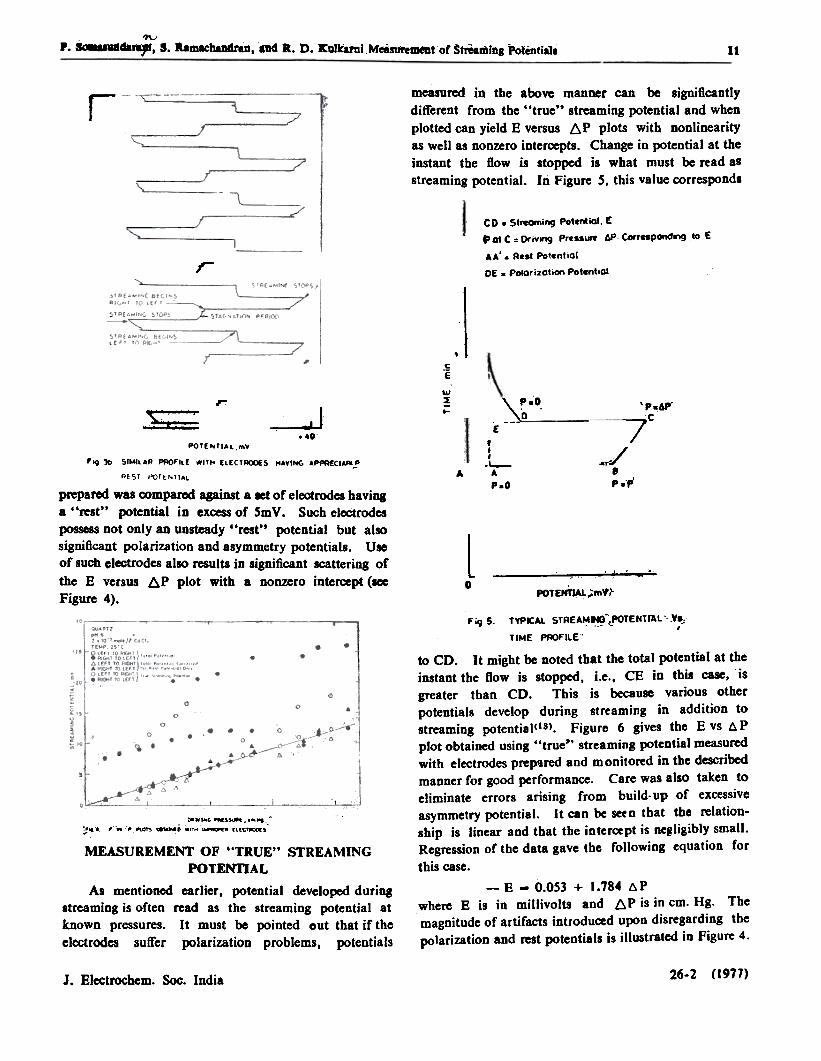
measured in the above manner can be significantlydifferent from the "true" streaming potential and whenplotted can yield E versus ~p plots with nonlinearityas well as nonzero inter~ts. Change in potential at theinstant the flow is stopped is what must be read asstreaming potential. In Figure S. this value corresponds
r
co. Strcoming Pot~iOI, EftGt C = Orivlng PressurY toP C«rnpondng ,to E
AA'. Rest Potential
DE . poIorizatlM\ Patentlolr
~
c
"e
tAl2:..
\:':0.r 'P.4p.
.c
7J. '0~~~ (
t.I
-I.--AP.O
,ay'"/.'.'P'A
POTE..TIAl,mV
~'9 3b SIMIlAP PllQFllE NITh (LECTPOOfS HAVIIOG 4PPA£CIAAI.!
~fST POTENTIAL
prepared was oompared against a let of electrodes havinga "rest" p>tential io ex~ of SmV. Such elel:trodespossess not only an unsteady "rest" potential but alsosignificant polarization and asymmetry potentials. Useof such electrodes also results in significant scattering ofthe E versus AP plot with a nonzero inte~pt (~Figure 4).
l0 ~. .' . -. ."
POTENnAL;;""tr
Fig 5. TYPICAl STREA~~~POTENTrAL".Y..:,TIME PROFILE"
to CD. It might be noted that the total potential at theinstant the flow is stopped, i.e., CE in this case, isgreater than CD. This is because various otherpotentials develop during streamjng in addition tostreaming potential<IS). Figure 6 gives the E vs 6, Pplot obtained using "true" streaming potential measuredwith electrodes preptlred and monitored in the describedmanner for good performance. Care was also taken toeliminate errors arising from build-up of excessiveasymmetry potential. It can be setn Ihat the relation-ship is linear and that the intercept is RC8ligibly small.Regression of the data gave the following equation for
this case.
~ ~... .
- "~.." ..."~ ~ -. .". -" ['[CT~,
MEASUREMENT OF "TRUE" STREAMINGPOTENTIAL
As mentioned earlier, potential developed duringstreaming is often read as the streaming potential atknown pressures. It must be pointed out that if theelectrodes suffer polarization problems, potentials
- E - 0.053 + 1.784 t.Pwhere E is in millivolts and 6P is in cm. "g. Themagnitude of artifacts introduced upon disregarding thepolarization and rest potentials is illustrated in Figure 4.
(1977)26-2J. Electrochcm. Soc. India
12;7\..
P. SQO1ASUoda:raat;S;'Ra~handraft,aDd:R;D[1I{~kbmi M~r~tQf St~mi~~pti9.ls,
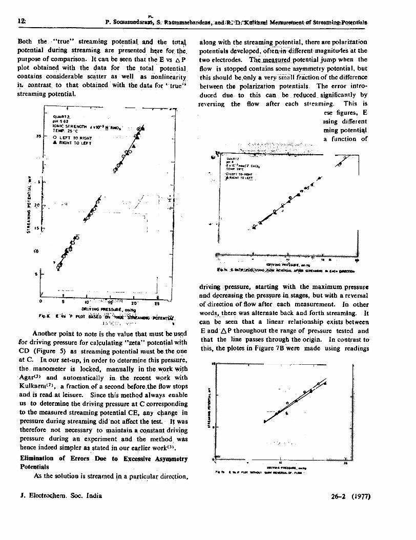
Both tbe "true" streaming potential, and the tot~potential during streamin8 are presen~ed he;re fQr tpepUt~se of comparison. It can be seen that the E ~s ~'pplot obt~ined with the data for the t~tal. potentialcontain$ considerable scatter as we" as nonlinearityi~ contrast to that obtained with the data for '-true"
streaming potential.r-- ~-.
along with the stre~mi_ng potential. there are polarizationpotentials d~veloped. oflei~djfferentmagnitutjes at thetwo electrodes. Tb_~~!,I~9~tential jump when theflow is stopped contains some asymmetry potential. butthis should be,Qoly a verysma1ffraction of the differencebetween the polarization potentials. The error intro-duced due to this can be Iedy~d~~ignificantly byreversing the flow after each streaming. This isillustrated in Figures fA and 78,- _In these figures, Evs. tJo P plots for a singl~ system but-using differentmeasuring sequeD~ are presented. Streaming poten1i~plotted in Figure 7 A was measured as a function of
I .L ' ,- ~ r".' I~ 40, ' I. ,I "';:j : ' ::
~ "iJ' "it ~
~
7l~oJD t- CU.A'l...,-2, IC"'-lf CaC..f(MP "oC
01.(" to---~
:~R""'f fOl~'~
QUARTZ,pH 562IONIC 5TRENGT" ..tO~~~'kNOaTEMP 25'C
~5 0 LEFT TO AI~.. RIGHT TO LEFT
1I
~'. 4Jt! ~;
..J...~~z..
~. 2.~zic..~ I;;
~". 1~"Oj~ '
:;:i~ !~
! tl
~1"5
ft.
y/
,
~~
;)J:1;1(0~ . 'to - ".. .IYt/OGPR~~. COI",
'.;70 :.~~i)JSIHG~k~~ sr --. _Do
..
I!
driving pressure, starting with the maximuw pressur,and d~creasing the p...es~ur~ ins~ges, but with a reversalof direction of flow after each measurement. In otherwords,)here was alternate back and forth streaming. Itcan be seen that a linear relationship exists betweenE aQd~ P throughout the range of pre:.sure tested andthat the line passes through the origin. In coQ~ast tothis, the plotes in Figure 7 B 'were made using readings
, ! l:tJ £ - - J
rt I I I ~ .-- 5 . IO('!.T'i5' :"'9 2-0- a; ~-
MlIYING PAfS~I.. "",HeFig,": E-i,. 'PPlot ~t:t:o'~~'~U:;iS'trRf;.-,~rlit,
j c,cO:'; "'1' ( .
0
:71O..AT'
. .00" ~/((oQ.,.. "'COLIF' 'O A,...'. A_' TO LB'
t~'tO
g i
i Ir~
.
~
~~ . ..
OR'W P '.." ..P PlOt -. ~.
Another point to note is the value that must ~u~d(or driving pressure for caJ~uJating "zeta" potent!~1 wi~hCD (Figure 5) as streaming potential must bethep~eat C. In our set-up, in order todetermiDe this pres$ure,the manometer is Jocked, manuaJly in ~he ~o~k wjJhAgar()) and automatically in the receot wpr:k withKulkarnl(7), a fraction <>f a second beforetbe flow &tqpsand is read at leisure. S.iQcetbis methQd always enab.leus to determine the driving pressure at C cprrespondingto the measured streaming potential CE, ~Y cpange inpressure during streaming did not affect the test. It wastherefore not necessary to maintain ~ CQnsta~t dl'ivipgpressure during an experiment and the method washence indeed simpler as,stated in our earlier work(3).
Elimination of Errors Due to E~Ce$Si'e Asym-.etryPotentials
As the solution is streAmed,n ap~rtic!1la(dir~tion,
J. EJectrocbem. Soc. India 26-2 (1971)
;r f ; J[.
r ; ' / . " .,.; fo. c ' ! t., . - ~ / ~~!
I. '1 1" ,J
5 t' I. i,.. '\
.. ...,', "I I
, .'
'7\;P. SOmIsuJtdarspi, S. Ramachandran, and R. D. Kulkarni Measurem~nt of Streaming Potentials. 13
obtained without flow reversa' after each streaming.Most of the solution was streamed to one bulb andreadings were obtained starting at the highest pressureand decreasing the pressure slowly. For a completesran of zero to maximum pressure tested, the solutionwas streamed in only one direction with no reversal.The prccess was then repeated in the other direction ofstre..ming. Unlike the one in Figure 7A, the plots inFigure 78 do show a definite curvature. E vs /:).P plotsobtained individually for the left to right streaming dohave finite intercepts. Reversal of flow after eachmeasurement was found to be particularly useful whenthe electrode characteristics are unsatisfactory.
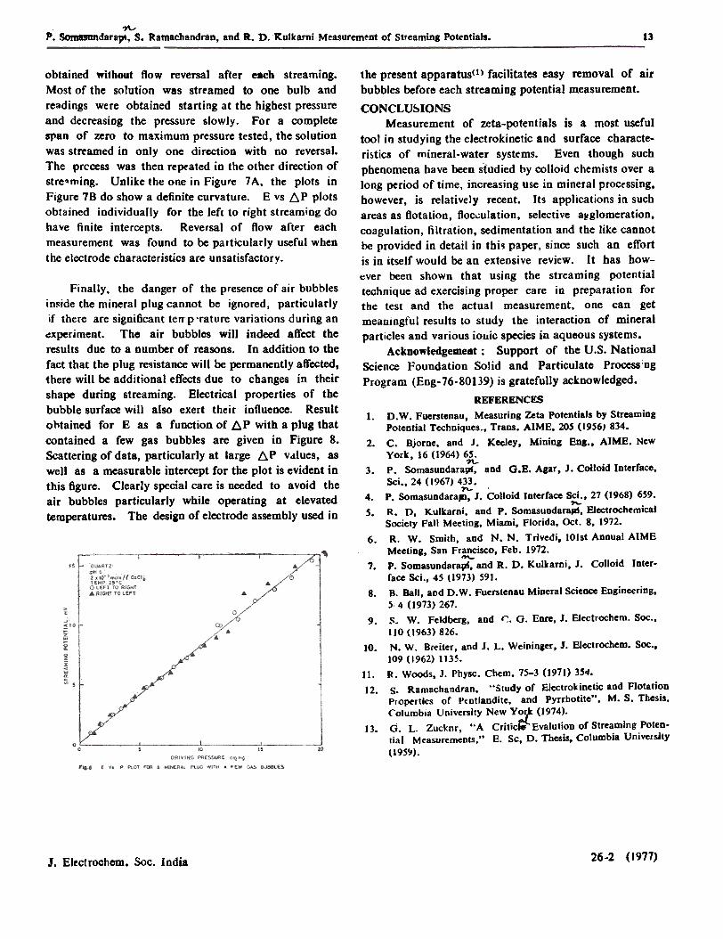
Finally, the danger of the presence of air bubblesin~ide the mineral plug cannot be ignored, particularlyif there are significant telTp 'rature variations during an~xperiment. The air bubbles will indeed affect theresults due to a Dumber of reasons. In addition to thefact that the plug resistance will be permanently affected,there will be additional effects due to changes in theirshape during streaming. Electrical properties of thebubble surface will also exert their influence. Resultobtained for E as a function of ~p with a plug thatcontained a few gas bubbles are given in Figure 8.Scattering of data, particularly at large ~p v.ilues, aswell as a measurable intercept for the plot is evident inthis figure. Clearly special care is needed to avoid theair bubbles particularly while operating at elevatedtemperatures. The desian of electrode assembly used in
the present apparatus(l) facilitates easy removal of airbubbles before each streaming potential measurement.
CONCLUSIONSMeasurement of zeta-potentials is a most useful
too1 in studying the electrokinetic and surface characte-ri~tics of mineral-water systems. Even though suchphenomena have been stUdied by colloid chemists over along period of time, increasing use in mineral processing,however, is relatively recent. Its applications in suchareas as flotation, floc.:,ulation, selective a~glomeration,coagulation, filtration, sedimentation and the like cannotbe provided in detail in tbi1 paper, since such an effortis in itself would be an extensive review. It has how-ever been shown that using the streaming potentialtechnique ad exercising proper care in preparation forthe test and the actual measurement, one can getmeaningful results to study tbe interaction of mineralparticles and various iollic species in aqueous systems.
Acknowledgement: Support of the U.S. NationalScience Foundation Solid and Particulate Process'ngProgram (Eng-76-80139) is gratefully acknowledged.
REFERENCF$1. D.W. Fuerstenau, Measuring Zeta potentials by Streaming
Potential Techniques., Trans. AIME, 205 (1956) 834.2. C. Bjome, and J. Keeley, Mining Bug., AIMB. New
York, 16 (1964) 65.')'l..
3. P. Somasundarapr, and G.E. Asar, J. Colloid Interface,Sci., 24 (1967) 433.
1'\.-4. P. Somasuodarapl, J. Colloid Interface Scl., 27 (1968) 659.
., 5. R. D, Kulkarni, and P. SoroasuDdar~, Electroc~mical
Society Fall Meeting, Miami, Florida, Oct. 8, 1972.6. R. W. Smith, and N. N. Trivedi, 10Ist Annual AIME
Meeting, SaD Francisco, Feb. 1972.--7. P. Somasundarapf, and R. D. Kulkarni, J. Colloid Inter-
face Sci., 45 (1973) 591.8. B. Ball, aod D. W. Fuerstenau Mineral Science Engineering,
5.4 (1973) 267.9. S. W. Feldbers, and 1::. G. Enre, J. Electrochem. Soc.,
110 (1963) 826.10. N. W. Bceiter, and J. L. Weininger, J. Electrochem. SOc.,
109 (1962) 1135.11. R. Woods, J. Physc. Chern. 75-3 (1971) 3~4.12. S. Ramachandran, "Studyof Electrokinetic and Flotation
Ploperties of P(ntlandite. and pyrrhotite", M. S. Thesis.Columbia University New Y~ (1974).
13. G. L. Zucknr. ., A Criticlei Evalution of Strraming Poten-tial M~asurements." E. Sc, D. Thesis, Columbia Univelsity
(I 9S~).
26-2 (1977)J. Electrochcm. Soc. India