Embed Size (px)
Citation preview
MEASUREMENT OF RESIDUAL STRESSESIN CLEARWELDS USING PHOTOELASTICITY
Satish Anantharaman and Avraham Benatar, The Ohio State UniversityNicole Woosman and Scott Hartley, Gentex Corporation.
Abstract
Residual stresses are detrimental to a plastic joint for anumber of reasons. They lead to reduced strength andfatigue life in joints, act as stress concentrators and causecrazing, cracking when exposed to solvents. In this paper,the residual stresses in Clearweld1 joints were measuredusing photoelasticity. This interference based techniquewas used in conjunction with a stress separation algorithmto quantify the maximum residual stress level and thestress distribution in the weld region. Also, the effects ofprocess parameters like welding speed, power and inksolvents on residual stresses were evaluated. The GEsolvent test was also employed for comparison with thephotoelasticity results. A comparison of the residualstresses between various joining processes was also made.
Introduction
The use of lasers to join plastics and composites isgaining momentum in the automotive, medical, packagingand a number of other industries, especially for throughtransmission infrared welding (TTIR) processes. Theinherent advantages of this technique being that it is a non-contact process that does not require relative motionbetween the components joined. Also, through multi-axisCNC machines it is possible to weld complicated contoursat high welding speeds. However, one of the primarydrawbacks of TTLW is that one of the components has tobe transparent to the wavelength of the laser beam usedand the other opaque.
Clearweld [1] is an innovative laser joining technique,which has all the advantages of conventional TTIR coupledwith the fact that it can be used to weld two infraredtransparent parts to each other. Welding of two infraredtransparent materials is possible by applying a laserabsorbing layer at the interface. Upon absorption, theenergy of the laser beam is converted to heat causingmelting and fusion to take place due to conduction. Theabsorber becomes colorless after the welding processthereby creating a seamless weld between the twocomponents. The presence of the absorbing layer yieldsgreater flexibility in process parameters for achieving thedesired strength and toughness.
1 Clearweld is a registered trademark of TWI.
The primary parameters involved in the Clearweldprocess are: power, welding speed, applied pressure, andquantity of the absorber. This work investigated the effectof variations in the above-mentioned process parameterson residual stresses formed. The residual stresses inClearweld joints were quantified using photoelasticity andsolvent testing. A comparison of residual stresses wasmade between Clearweld and other plastic joiningtechniques. The effect of ink solvents on the strength ofthe joint was also studied. Polycarbonate was chosen asthe material for analysis because of its excellentengineering and optical properties [2].
Background
Photoelasticity theory
Photoelasticity has emerged as a powerful tool in thequantification of residual stresses in plastic welds.Although the use of the technique is limited to birefringentplastics like polycarbonate and PETG, it provides powerfulinsights into residual stresses in viscoelastic materials.Photoelasticity in itself is only an indicator of the principalstress difference at any point on the sample. In order tocalculate the normal stress distribution along andperpendicular to the weld a stress separation algorithm isemployed. The algorithm is derived from a finitedifference approximation involving the shear differencetechnique [3]. A grid system was employed and thefollowing basic equations were used to determine shearstresses and normal stress differences at each station in thegrid [4].
( ) ( ) ( )
( ) ( ) ( ) ( ) jijijiyjix
jijijixy
Ntf
Ntf
,,,,
,,,
2cos
2sin2
1
θσσ
θτ
=−
=
(1)
Where f is the stress optic coefficient [2] for polycarbonate,t is the thickness of the sample Ni,j and θi,j are the fringeorder and the isoclinic angles at each station. The isoclinicangles were measured positive counterclockwise from thex-axis to the direction of the greatest principal stress. Itwas determined from previous analysis that the stressesperpendicular to the weld were of the highest magnitudeand therefore the most important for analysis. The
ANTEC 2003 / 1051
maximum stress was determined by using the followingequation:
( ) ( ) ( ) ( )[ ]
( ) ( )[ ] 02
1
2
1
1,11,11,11,1
,1,
,1,1,1,1
,1,,1,
=−
−−
+−
−−
+−
+−+++−++
+
−+−+
++
jixyjixyjiji
jiji
jixyjixyjiji
jijijixjix
yy
xx
yy
xx
ττ
ττσσ
(2)
To simplify the calculations, the boundary and thesymmetry conditions were used in determining the shearstresses and the normal stress difference. Starting from theboundary where the stress normal to the boundary is zero,the normal stress values were sequentially calculated andplotted along the grid lines.
Experimental Procedures
Welding
Prior to welding, samples were prepared by applyingmethoxy-propanol (MOP), methyl ethyl ketone (MEK), orethanol-based inks containing the absorber to the end of aprecut sheet 7.2cm by 2.5 cm. The samples were thenpressed end to end in a butt joint configuration. A 940 nmdiode laser was used to transmit the laser beam throughone part to scan the interface. The effect of scan speed andpower was evaluated by varying the scan speed from 0.12m/min to 1.5 m/min and the power from 90 to 300 Watt.The pressure was removed immediately after welding.
Tensile Testing
The welded samples were tensile tested to determinejoint strength and energy to fracture. The testing was doneon a computer controlled Instron (Model No. 4468) tensiletesting machine. The cross-sectional dimensions of thesamples were 25.4mm x 2.5 mm. The crosshead speed wasset at 5 mm/min.
Photoelasticity
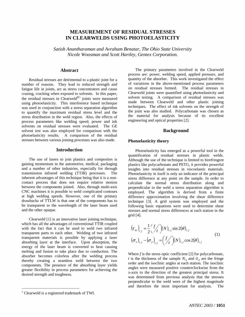
The residual stresses developed due to the weldingprocess were measured using photoelasticity. Thechallenge presented by the very small heat affected zone(HAZ) in Clearweld joints was overcome by the use ofpolarized microscopy. Magnifications of 5X and 10X wereemployed in order to determine isochromatic (linesindicating regions having the same principal stressdifference) fringe order. The setup was initially calibratedin order to ensure accurate calculations [2]. A dark fieldpolariscope (see Figure 1) was used to map the isoclinicfringes (lines indicating principal stress orientation). Withthe help of the fringe maps and the equations mentionedabove, normal residual stresses perpendicular to theorientation of the weld were calculated.
Solvent testing
The solvent testing technique [5] was used in order toserve as a comparison to the results of photoelasticity. Thewelded parts were exposed to varying concentrations ofacetone in methanol for a period of three minutes. Thesamples were then observed for cracking and crazing alongthe weld. The lowest concentration of the solution thatcaused cracking was noted down and the correspondingresidual stress values were obtained from the critical stressversus concentration chart for polycarbonate [5].
Residual stress effects
The effects of residual stresses on joint strength andenergy to fracture of Clearweld was investigated byexposing the sample to a low concentration of solvent,followed by tensile testing. The sample was exposed to a10% acetone in methanol solution for 3-4 minutes. Thesamples were then dried in a vacuum oven and tensiletested. The strength of the samples was compared to that ofwelded samples that were not exposed to the solvent.
Results and Discussion
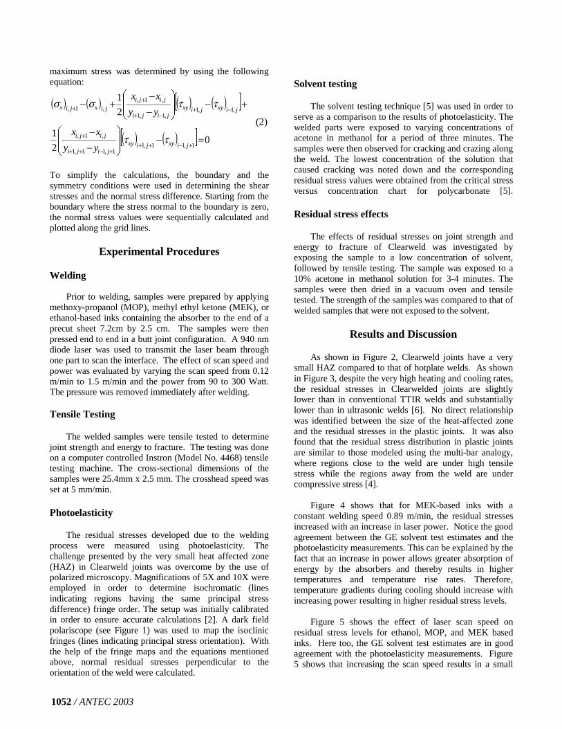
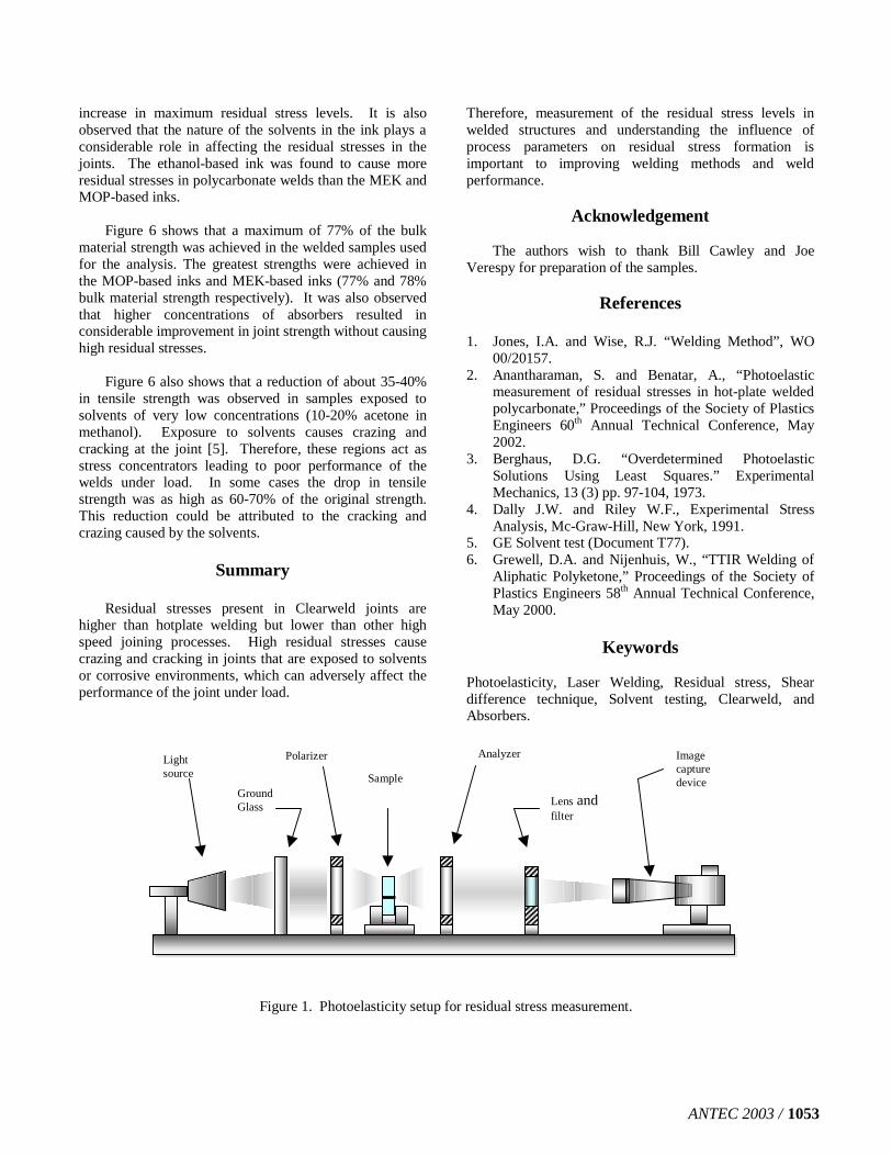
As shown in Figure 2, Clearweld joints have a verysmall HAZ compared to that of hotplate welds. As shownin Figure 3, despite the very high heating and cooling rates,the residual stresses in Clearwelded joints are slightlylower than in conventional TTIR welds and substantiallylower than in ultrasonic welds [6]. No direct relationshipwas identified between the size of the heat-affected zoneand the residual stresses in the plastic joints. It was alsofound that the residual stress distribution in plastic jointsare similar to those modeled using the multi-bar analogy,where regions close to the weld are under high tensilestress while the regions away from the weld are undercompressive stress [4].
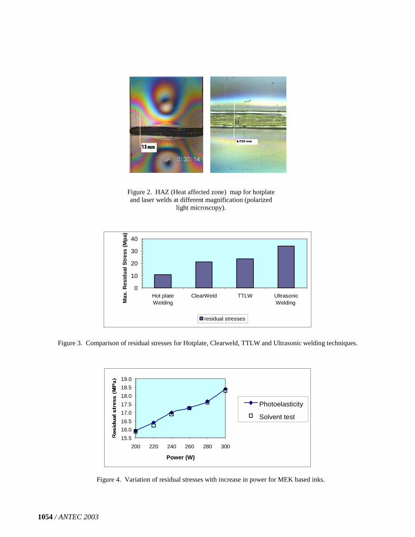
Figure 4 shows that for MEK-based inks with aconstant welding speed 0.89 m/min, the residual stressesincreased with an increase in laser power. Notice the goodagreement between the GE solvent test estimates and thephotoelasticity measurements. This can be explained by thefact that an increase in power allows greater absorption ofenergy by the absorbers and thereby results in highertemperatures and temperature rise rates. Therefore,temperature gradients during cooling should increase withincreasing power resulting in higher residual stress levels.
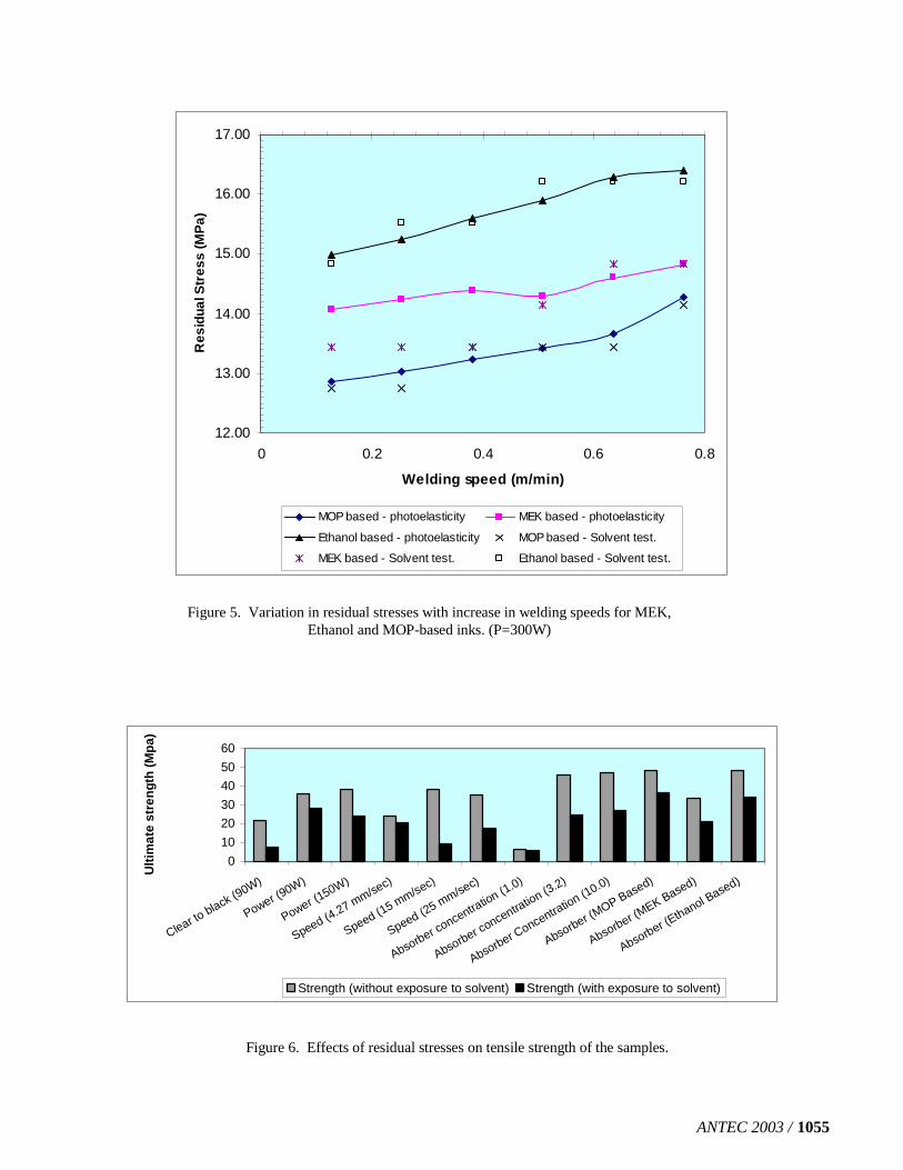
Figure 5 shows the effect of laser scan speed onresidual stress levels for ethanol, MOP, and MEK basedinks. Here too, the GE solvent test estimates are in goodagreement with the photoelasticity measurements. Figure5 shows that increasing the scan speed results in a small
1052 / ANTEC 2003
increase in maximum residual stress levels. It is alsoobserved that the nature of the solvents in the ink plays aconsiderable role in affecting the residual stresses in thejoints. The ethanol-based ink was found to cause moreresidual stresses in polycarbonate welds than the MEK andMOP-based inks.
Figure 6 shows that a maximum of 77% of the bulkmaterial strength was achieved in the welded samples usedfor the analysis. The greatest strengths were achieved inthe MOP-based inks and MEK-based inks (77% and 78%bulk material strength respectively). It was also observedthat higher concentrations of absorbers resulted inconsiderable improvement in joint strength without causinghigh residual stresses.
Figure 6 also shows that a reduction of about 35-40%in tensile strength was observed in samples exposed tosolvents of very low concentrations (10-20% acetone inmethanol). Exposure to solvents causes crazing andcracking at the joint [5]. Therefore, these regions act asstress concentrators leading to poor performance of thewelds under load. In some cases the drop in tensilestrength was as high as 60-70% of the original strength.This reduction could be attributed to the cracking andcrazing caused by the solvents.
Summary
Residual stresses present in Clearweld joints arehigher than hotplate welding but lower than other highspeed joining processes. High residual stresses causecrazing and cracking in joints that are exposed to solventsor corrosive environments, which can adversely affect theperformance of the joint under load.
Therefore, measurement of the residual stress levels inwelded structures and understanding the influence ofprocess parameters on residual stress formation isimportant to improving welding methods and weldperformance.
Acknowledgement
The authors wish to thank Bill Cawley and JoeVerespy for preparation of the samples.
References
1. Jones, I.A. and Wise, R.J. “Welding Method”, WO00/20157.
2. Anantharaman, S. and Benatar, A., “Photoelasticmeasurement of residual stresses in hot-plate weldedpolycarbonate,” Proceedings of the Society of PlasticsEngineers 60th Annual Technical Conference, May2002.
3. Berghaus, D.G. “Overdetermined PhotoelasticSolutions Using Least Squares.” ExperimentalMechanics, 13 (3) pp. 97-104, 1973.
4. Dally J.W. and Riley W.F., Experimental StressAnalysis, Mc-Graw-Hill, New York, 1991.
5. GE Solvent test (Document T77).6. Grewell, D.A. and Nijenhuis, W., “TTIR Welding of
Aliphatic Polyketone,” Proceedings of the Society ofPlastics Engineers 58th Annual Technical Conference,May 2000.
Keywords
Photoelasticity, Laser Welding, Residual stress, Sheardifference technique, Solvent testing, Clearweld, andAbsorbers.
Lightsource
GroundGlass
Polarizer
Sample
Analyzer
Lens andfilter
Imagecapturedevice
Figure 1. Photoelasticity setup for residual stress measurement.
ANTEC 2003 / 1053
0
10
20
30
40
Hot plateWelding
ClearWeld TTLW UltrasonicWeldingM
ax.R
esid
ual
Str
ess
(Mp
a)
residual stresses
Figure 3. Comparison of residual stresses for Hotplate, Clearweld, TTLW and Ultrasonic welding techniques.
15.5
16.0
16.5
17.0
17.5
18.0
18.5
19.0
200 220 240 260 280 300
Power (W)
Photoelasticity
Solvent test
Figure 4. Variation of residual stresses with increase in power for MEK based inks.
Figure 2. HAZ (Heat affected zone) map for hotplateand laser welds at different magnification (polarized
light microscopy).
1054 / ANTEC 2003
12.00
13.00
14.00
15.00
16.00
17.00
0 0.2 0.4 0.6 0.8
Welding speed (m/min)
Res
idua
lStr
ess
(MP
a)
MOP based - photoelasticity MEK based - photoelasticity
Ethanol based - photoelasticity MOP based - Solvent test.
MEK based - Solvent test. Ethanol based - Solvent test.
0
10
20
30
40
50
60
Clear to black (90W)
Power (90W)
Power (150W)
Speed (4.27 mm/sec)
Speed (15 mm/sec)
Speed (25 mm/sec)
Absorber concentration (1.0)
Absorber concentration (3.2)
Absorber Concentration (10.0)
Absorber (MOP Based)
Absorber (MEK Based)
Absorber (Ethanol Based)
Ult
imat
est
ren
gth
(Mp
a)
Strength (without exposure to solvent) Strength (with exposure to solvent)
Figure 6. Effects of residual stresses on tensile strength of the samples.
Figure 5. Variation in residual stresses with increase in welding speeds for MEK,Ethanol and MOP-based inks. (P=300W)
ANTEC 2003 / 1055


![Prediction of welding residual stresses using machine ... · characterise the distribution of residual stresses in structural welds [6, 7]. With the development of residual stress](https://img.pdfslide.us/doc/110x75/5fa3f63f3be93a3412525cc3/prediction-of-welding-residual-stresses-using-machine-characterise-the-distribution.jpg)