Embed Size (px)
Citation preview
MEASUREMENT OF LOW RESISTANCE BY MEANSOF THE WHEATSTONE BRIDGE.
By Frank Wenner and Alva Smith.
ABSTRACT.
Resistances which are small can be definite only if they have distinct current andpotential terminals.
In the procedure proposed the current terminals serve for connecting the resistance
into the bridge circuit while the potential terminals serve as branch points. This
puts the connecting resistances into arms adjacent to the arm containing the unknownresistance. Therefore their effect is made smaller than for the usual arrangement
in the ratio of the unknown resistance to the resistance of the adjacent arms.
In cases where the errors still caused by the connecting resistances need be con-
sidered, two supplementary measurements with the same apparatus may be madepractically to eliminate them.
With a recently calibrated bridge a resistance of the order of o.ooi ohm was meas-
ured to an accuracy of 0.6 per cent directly, and 0.03 per cent after applying the
correction obtained by the supplementary measurement.
The values of the resistances are obtained from the data for the most part
by addition and subtraction rather than by multiplication and division.
CONTENTS.Page.
1. Introduction 297
2. Necessity for definite terminals 298
3
.
Bridge arrangement 298
4. Primary measurement 299
5. Secondary measurement 300
6. Discussion of results 303
7. Summary 305
1. INTRODUCTION.
The engineer or the physicist often would like to know the
resistance of a conductor having a resistance as low as 0.01 ohmor even 0.001 ohm. The unknown resistance may be that of a
shunt, a reel of insulated cable, a sample for conductivity measure-
ment or other low resistance whose value is required to an accuracy
of a half of 1 per cent or better. Usually, however, a Thomsonbridge or other special equipment is considered essential for such
a measurement, but may not always be at hand. The purpose
of this paper is to show that measurements of such conductors
may be made to a fairly high accuracy by means of the Wheatstone
bridge with the usual accessory apparatus.
63653°—24 297
298 Scientific Papers of the Bureau of Standards. W* v
2. NECESSITY FOR DEFINITE TERMINALS.
If a conductor of such low resistance is to have its resistance
definite it must have distinct current and potential terminals.
Most shunts are provided with these. Other conductors to be
tested should be supplied with such terminals. In case of wires and
cables if the ends are taken for two of the terminals each of the
other 'terminals should be placed in from Hie ends a distance
corresponding to at least several diameters of the conductor^ The
resistance measured then is of that part of the conductor which is
between the inner terminals. A knife edge or rubbing contact
should not be used as a terminal except under conditions such that
there is little or no current through it, or its resistance does not
materially affect the results obtained. Terminals should be sol-
dered or screw connected in cases in which their resistance enters
directly into measurements.
J Hi-1
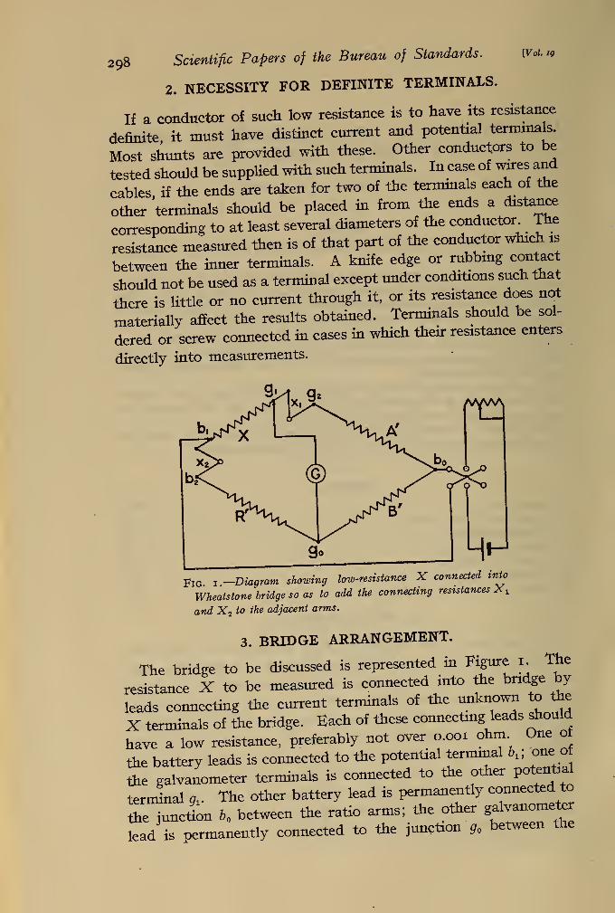
Fig i -Diagram showing low-resistance X connected into
Wheatstone bridge so as to add the connecting resistances X,
and X2 to the adjacent arms.
3. BRIDGE ARRANGEMENT.
The bridge to be discussed is represented in Figure I. The
resistance X to be measured is connected into the bridge by
leads connecting the current terminals of the unknown to the
X terminals of the bridge. Each of these connecting leads should
have a low resistance, preferably not over o.ooi ohm. One of
the battery leads is connected to the potential terminal \;
the galvanometer terminals is connected to the other potential
terminal 9l . The other battery lead is permanently connected to
L junction o between the ratio arms; the other galvanometer
lead is permanently connected to the junction g between the
wenner-\ Measurement of Low Resistance. 299Smith J
'
higher ratio arm and the rheostat arm. The ratio arm A ' adjacent
to the unknown resistance is set at its lowest or the next to the
lowest value and the other ratio arm B' set 60 that the rheostat
arm R' reads, at balance, at least 500 times larger than the un-
known resistance.
In the battery circuit there should be included a reversing
switch, by means of which the current through the bridge may
be opened or closed in either direction. A rheostat should be
used in the battery circuit to limit the current to that which
the lower ratio arm can carry without an excessive rise in tem-
perature.
The characters used in Figure 1 to designate the arms of the
bridge also represent the respective resistance of these arms.
xxand x2 axe the resistance between the potential terminals of
X, and A' and R'', respectively.
4. PRIMARY MEASUREMENT.
When the resistances xxand x2 are taken into consideration,
the usual bridge relation gives
X=^p^(R'+x2) (1)
Obviously, A', B'', and R' must each be known to as high a pre-
cision as is sought in the measurement of X. On the other hand
Xi and x2 will be small in comparison, respectively, with A' and
R' and, therefore, need not be known to such high precision.
In fact, they may be neglected altogether where high accuracy
is not required. As R' is usually small, it is necessary to read
deflections of the galvanometer and determine R' by interpola-
tion to less than 1/10 of the smallest change that can be made in
the rhoestat arm.
If, as a first approximation, we ignore xxand x2 ,
equation (1)
becomes
It is presumed that the bridge is in good adjustment or that cor-
rections to the various readings are known and will be applied.
The following numerical examples taken from laboratory data
will illustrate the accuracy that may be expected in the use of
this equation. Appropriate corrections have been applied to the
300 Scientific Papers of the Bureau of Standards. [VoUiq
readings of the bridge arms. The data given in these examples
represent, therefore, actual resistances, not merely readings, of
these arms. For a first example:
A' = 1.00045
B' = 1000.0
R' = 9.9898 ohms.
These data give
X = 0.009994 ohm.
The conductor under test in this case was a 0.01 ohm standard
whose accepted value is 0.0100025 ohm. It follows, therefore,
that the error in the measured value amounts to but 0.08 per
cent. For a second example
:
A' = 0.10023
B' = 1000.0
R' = 9.9188 ohms.
These data giveX = 0.0009942 ohm.
The conductor under test in this case was a 0.001 ohm standard
whose accepted value is 0.000999997 ohm. The error in the
measured value in this case is 0.58 per cent.
The errors arising from the above procedure are very small
compared with those that would exist if the usual procedure with
the Wheatstone bridge were followed in the measurement of these
low resistances. These errors are low because the connecting
resistances to the unknown have been thrown over into the adja-
cent arms of the bridge, which are high compared with the con-
necting resistances; whereas, with the usual arrangement, they
would be included with the unknown, and as they may be of the
same order of magnitude might introduce an error of the order of
100 per cent. For many purposes the accuracy of the above
procedure is sufficient.
5. SECONDARY MEASUREMENT.
However, where higher accuracy is desired it can be obtained
by taking into consideration the small effects of the connecting
resistances %xand x2 , which were neglected in the preceding
calculation. This requires two additional measurements, but
these may be made without additional apparatus. Further,
neither of these need to be made to a high accuracy, since they
serve only for the purpose of determining small corrections to the
s^er
]Measurement of Low Resistance. 301
primary measurement. We shall, therefore, refer to these as
secondary measurements.
One of these secondary measurements is made with the gal-
vanometer lead transferred from gx to g2 , the other connections
remaining as for the primary measurement. The bridge is thenbalanced by adjustment of the rheostat arm only. If R\ is
the resistance of the rheostat arm, the relation between the resist-
ances is
X + x, A'R\+x2 B>
(3)
The other secondary measurement is made with the galva-
nometer lead transferred from g2 back to g1 and the battery lead
transferred from bx to b2 . The rheostat arm is again adjusted
until balance is obtained. If R\ is the resistance of the rheostat
arm the relation between the resistances is
X+x2 _ A'+x1 / n
R', " B'W
Equations (1), (3), and (4) are three independent relations be-
tween X, xlf x2 , and the resistances of the bridge arms, fromwhich it is possible to determine X, x^, and x2 . However,values for %x
and x2 usually are not desired, and an exact solution
of the three equations for X leads to a complicated expression
from which the value can not readily be calculated. To obviate
this difficulty, we shall write
A+aiorA' R+rx ioxR\B + b for B' R+r2 iorR'2
R+r for R'
where A, B, R are simple nominal values, such as 0.1, 0.2, 0.5,
1, 2, 5, 10, etc., ohms, and a, b, r are the small amounts by whichthe actual resistance of the bridge arms exceed these simple
nominal values.
Because of the approximations to be made later in the equations,
A and B should not differ from A' and B' by as much as 1 per cent
and R should not differ from R' by more than a few per cent, if
an accuracy better than 0.1 per cent is desired. In some cases,
therefore, it will not be possible to choose for R as simple a valueas that indicated above, or as for A and B. However, in all
cases the simplest possible values consistent with this limitation
should be chosen for A, B, and R.
3o2 Scientific Papers of the Bureau of Standards. lvd. I9
For example should
A' = 1.0022
£' = 1003.3
and #' = 25.354 ohms
we would choose
A = i
5 = 1,000
and R = 25 ohms.
If these changes in notation are made, equation (1) becomes
Since the terms containing x, and x2 are small compared with
unitv they need not be known to a high precision. Therefore,
: A' A A V __ARin equation (3) we may neglect x2 ,
consider ^-, = g> ana JL - B•
This gives
^=4(n-^) (6>
Likewise, in equation (4) we may neglect x1}consider £/ = #' and
X=^p This gives
x2=^(ir
2-r) (7)
These values of xt and x2substituted in equation (5) give
__ ARr a b r r,-r AJ^^ rj^-rf\X==-Wl
I+A~B+ R+ ~B-+ BR + BR J
{)
Here we have neglected squares and cross products of small
quantities, except one which may sometimes be significant.
It is obvious that an alternative procedure consists in com-
puting the numerical values of x1and x2 from equations (3) and
(4) respectively. In this computation x2 is neglected in equation
(3) 'and xxin equation (4), and the value of X obtained from equa-
tion (2) is used. The computed values of xxand x2
are then sub-
stituted back in equation (1), from which the corrected value of
X can be obtained.
wamer] Measurement of Low Resistance. 303
The examples discussed above will now be extended to show the
effect of the two auxiliary measurements upon the accuracy
attainable.
For the first example:
A' = 1.00045, B' = 1,000.00, R' = 9.9898
Rx' = 10.480
and R2' = 10.72 ohms.
If we take A = 1, B = 1,000, R = 10,
it follows that = 0.00045, 6=0.00, r= —0.0102
rl= +0.48
and r2 = +0.72 ohm.
These values substituted in the right-hand member of equation
(8) give
X = o.oi (1+0.00045—0.00102+0.00049 + 0.00007) ohm= 0.0099999 ohm.
This differs from the known value by 0.025 per cent, whereas
the value obtained by the primary measurement alone differs
from the known value by 0.08 per cent.
For the second example
:
A' =0.10023, B' = 1,000.0, R' = 9.9188
tf\ = i5.45
and R'2= 14.1 ohms.
If we take A =0.1, B = 1,000.0, R = 10 ohms, it follows that
= 0.00023,6=0.0, r =— .0812
. *V=+5-45and r2 = +4.1 ohms.
These values substituted in the right-hand member of equation
(8) give
X=o.ooi (1 +0.0023— 0.00812 +0.00553+0.00004 — 0.00004) ohm=0.0009997 ohm.
This value differs from the known value by only 0.03 per cent,
whereas the value obtained by the primary measurement alone
differs from the known value by 0.58 per cent.
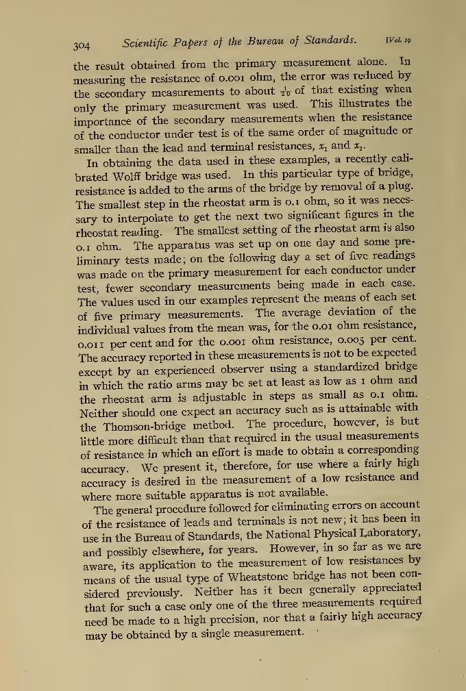
6. DISCUSSION OF RESULTS.
Inspection of these results shows that in measuring the resistance
of 0.01 ohm, the corrections resulting from the secondary measure-ments reduced the error to about one-third of that existing in
304 Scientific Papers of the Bureau of Standards. WoUq
the result obtained from the primary measurement alone. In
measuring the resistance of o.ooi ohm, the error was reduced by
the secondary measurements to about -fa of that existing when
only the primary measurement was used. This illustrates the
importance of the secondary measurements when the resistance
of the conductor under test is of the same order of magnitude or
smaller than the lead and terminal resistances, xxand x2 .
In obtaining the data used in these examples, a recently cali-
brated Wolff bridge was used. In this particular type of bridge,
resistance is added to the arms of the bridge by removal of a plug.
The smallest step in the rheostat arm is o.i ohm, so it was neces-
sary to interpolate to get the next two significant figures in the
rheostat reading. The smallest setting of the rheostat arm is also
o.i ohm. The apparatus was set up on one day and some pre-
liminary tests made; on the following day a set of five readings
was made on the primary measurement for each conductor under
test, fewer secondary measurements being made in each case.
The values used in our examples represent the means of each set
of five primary measurements. The average deviation of the
individual values from the mean was, for the o.oi ohm resistance,
o.on per cent and for the o.ooi ohm resistance, 0.005 per cent.
The accuracy reported in these measurements is not to be expected
except by an experienced observer using a standardized bridge
in which the ratio arms may be set at least as low as 1 ohm and
the rheostat arm is adjustable in steps as small as 0.1 ohm.
Neither should one expect an accuracy such as is attainable with
the Thomson-bridge method. The procedure, however, is but
little more difficult than that required in the usual measurements
of resistance in which an effort is made to obtain a corresponding
accuracy. We present it, therefore, for use where a fairly high
accuracy is desired in the measurement of a low resistance and
where more suitable apparatus is not available.
The general procedure followed for eliminating errors on account
of the resistance of leads and terminals is not new; it has been in
use in the Bureau of Standards, the National Physical Laboratory,
and possibly elsewhere, for years. However, in so far as we are
aware its application to the measurement of low resistances by
means of the usual type of Wheatstone bridge has not been con-
sidered previously. Neither has it been generally appreciated
that for such a case only one of the three measurements required
need be made to a high precision, nor that a fairly high accuracy
may be obtained by a single measurement.
Sa ct
]Measurement of Low Resistance 305
7. SUMMARY.
1
.
It is pointed out again that if a low resistance is to be definite,
it must have distinct current and potential terminals.
2. By using the potential terminals of the unknown as branchpoints of the bridge, the terminal and connecting resistances to
the unknown are thrown into the adjacent arms of the bridge. Bymaking the resistances of these arms high compared with theconnecting resistances, the error caused by the connecting resist-
ances is made at once relatively small.
3. In cases where it is desirable to corrcet for the small errors
mentioned above, it is shown that this may be done by two addi-
tional or auxiliary measurements with the same apparatus.
4. In the measurement of a resistance of the order of 0.001 ohman accuracy of 0.6 per cent was obtained by direct measurementand 0.03 per cent when corrections obtained by the auxiliary
measurements were applied.
Washington, July 24, 1)923.
J

Bil