Embed Size (px)
Citation preview
359Measurement of Energy Emitted by Pyrogenic Tablets Used for Ignition...
Central European Journal of Energetic Materials, 2015, 12(2), 359-375
Measurement of Energy Emitted by Pyrogenic Tablets Used for Ignition of Solid Rocket Propellants
Tomasz WOLSZAKIEWICZ 1,*, Zbigniew A. WALENTA 2
1 Institute of Industrial Organic Chemistry, Annopol 6, 03-236 Warsaw, Poland2 Institute of Fundamental Technological Research, Pawinskiego 5b, 02-106 Warsaw, Poland * E-mail: [email protected]
Abstract: In order to ignite a solid rocket propellant special igniting devices – pyrogenic tablets – must be used. The reported research was aimed at finding the best material for such pyrogenic tablets, which would successfully replace the still frequently used black powder. The measurement of heat, absorbed by the rocket propellant from various kinds of pyrogenic tablets against time, as well as tests of the ignition of the rocket propellant in a stationary engine, were performed. It was concluded, that of all of the mixtures considered, the best material for pyrogenic tablets was a mixture of 25% Zr and 75% KNO3.
Keywords: pyrogenic tablets, measurement of absorbed heat, ignition of rocket propellant
1 Introduction
Solid rocket propellants need special ignition devices for initiating and supporting their combustion. A properly performed process of ignition is necessary for their stable function. Black powder, the first substance used as an igniter and sometimes used even now, produces excessive heat fluxes, which result in large pressure increases at the beginning of ignition and influence, unfavourably, the subsequent combustion, making it unstable.
The mixture now most frequently used for igniters and very well described in the literature is B/KNO3 [1-3]. Zr/BaCrO4 [4, 5] and Zr/KClO4 [6, 7] are also
ISSN 1733-7178e-ISSN 2353-1843
360 T. Wolszakiewicz, Z.A. Walenta
commonly used. However, finding the optimum igniting substance is still an open problem – and is the subject of the present research project.
During the ignition period the solid propellant works under nonstationary conditions. Heat is transmitted from the igniter to the propellant and the heat flux usually varies very rapidly. The whole process is very complex and strongly dependent on the structure of the propellant, as well as on energetic parameters and the shape of the igniter [8, 9]. It has also been shown [10-12] that, in addition, it is dependent on the previous mechanical and thermal loading history of the propellant.
In order to optimize the ignition of a solid propellant it is necessary to monitor the temperature and pressure of the igniting gases against time. In this project we have proposed a method for measuring the energy received by the propellant from the pyrogenic tablets against time and selected, using this method, the best material for pyrogenic tablets from the several materials commonly used for this purpose. The selection of the material has been subsequently confirmed by ballistic tests in a specially designed stationary engine.
2 Materials and Methods
2.1 Substances proposed as materials for pyrogenic tabletsAs mentioned in the Introduction, the oldest substance used as an igniter for solid propellants is black powder. The substance most frequently used today is a mixture of boron and potassium nitrate(V) (B/KNO3). There are, however, some other substances which may be used as igniters and whose parameters are not sufficiently well known. In Table 1 we present a list of several igniting substances, including the most common B/KNO3 and some others, hitherto not so well known. In the present research project we have investigated two of them: Zr/KNO3 and Zr/KClO4 and compared them with the classical ones: B/KNO3 and black powder.
361Measurement of Energy Emitted by Pyrogenic Tablets Used for Ignition...
Table 1. Average mass of a single tablet and its specific energy for several kinds of tablet materials.
Composition of the tablet Percentage Specific energy[J/g]
Mass of the tablet [g]
flat lens-shapedB/KNO3
(type II-B MIL P46994B)40/60 7106.020/80 7003.0 0.1376
Al/KClO4 40/60 6854.5 0.1543 0.1793
Zr/KNO325/75 3705.017/83 3703.4 0.1398 0.1803
Zr/BaCrO435/65 1452.7 0.2188 0.243420/80 1087.5
Zr/KClO4 50/50 4315.4 0.1883 0.2243
2.2 Preparation of the pyrogenic tabletsThe igniter mixture of the required composition was dried for 4 h at 80 °C, and then granulated through a sieve 0.6-0.85 mm. It was dried once more for 6 h at 30 °C to achieve a moisture level below 0.65%. The dry fuel was then sieved through a sieve 0.6-1.2 mm and finally pressed to form the tablets of the required shape (flat and lens-shaped – Figure 1).
Figure 1. Pyrogenic tablets: “flat” (left) and “lens-shaped” (right).
2.3 Measurement of heat transfer from the igniter to the propellant
2.3.1 Principle of the methodThe method for measuring the heat flux between the hot flowing gas and the cool solid wall under nonstationary conditions was developed in the middle of the last century [13]. This method was based on measurement of the surface temperature of the wall, as it increased in time due to nonstationary heating. The measurement was done using a “heat transfer gauge” – a thin-film resistance thermometer deposited on the surface to be heated. This resistance thermometer recorded, with good accuracy and time resolution (about 1 µs), the temperature of the heated surface. By solving the heat conduction equation for the material
362 T. Wolszakiewicz, Z.A. Walenta
of the wall, with its varying surface temperature taken as the boundary condition, it was possible to obtain the heat flux to the wall.
The above method of measurement seems to be still useful today. Nowadays, however, it is possible to measure the temperature of the heated surface not just with resistance thermometers. Apart from that, the subsequent calculation of the heat flux, thanks to the availability of PC computers, is relatively easy and fast. The computer program used for this purpose is quite simple. However, the principle of the measurement remains unchanged.
The details of the method of measurement in its present form have been outlined in Appendixes 1 and 2.
2.3.2 Estimation of the necessary parameters of the measuring equipmentThe aim of the initial calculations was to estimate the necessary parameters of the measuring equipment to be used.
To estimate the behaviour of the combustion gases, the products of combustion of B/KNO3 tablets were considered. The program “ICT Thermodynamic Code” was used to estimate the composition of the products of combustion of these tablets (Table 2).
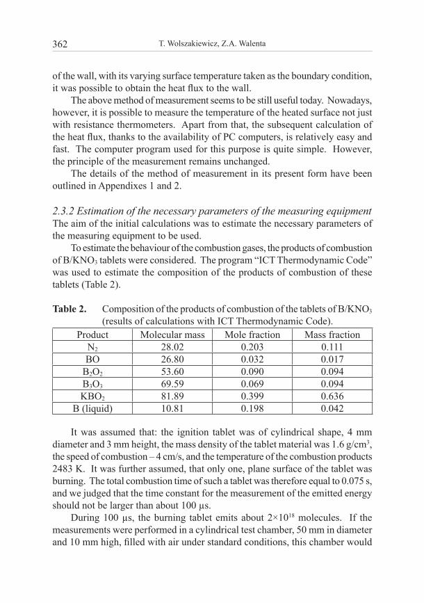
Table 2. Composition of the products of combustion of the tablets of B/KNO3 (results of calculations with ICT Thermodynamic Code).
Product Molecular mass Mole fraction Mass fractionN2 28.02 0.203 0.111BO 26.80 0.032 0.017
B2O2 53.60 0.090 0.094B3O3 69.59 0.069 0.094KBO2 81.89 0.399 0.636
B (liquid) 10.81 0.198 0.042
It was assumed that: the ignition tablet was of cylindrical shape, 4 mm diameter and 3 mm height, the mass density of the tablet material was 1.6 g/cm3, the speed of combustion – 4 cm/s, and the temperature of the combustion products 2483 K. It was further assumed, that only one, plane surface of the tablet was burning. The total combustion time of such a tablet was therefore equal to 0.075 s, and we judged that the time constant for the measurement of the emitted energy should not be larger than about 100 µs.
During 100 µs, the burning tablet emits about 2×10¹⁸ molecules. If the measurements were performed in a cylindrical test chamber, 50 mm in diameter and 10 mm high, filled with air under standard conditions, this chamber would
363Measurement of Energy Emitted by Pyrogenic Tablets Used for Ignition...
contain about 4.77×10²⁰ molecules. Such an amount of air in the test chamber would, most probably, strongly affect the measurements.
In order to check this more accurately, Direct Simulation Monte Carlo (DSMC) computations [14] were performed for the conditions specified above, and for the test chamber filled at atmospheric pressure and when evacuated. The ignition tablet was placed on the lower wall of the test chamber, close to its axis; the measuring gauge was placed on the upper wall, above the tablet, and 10 mm from it. It was assumed, that the pyrogenic tablet produced a stream of combustion gases of constant parameters, starting instantly at the beginning of the simulation.
According to the simulation results, the time necessary to stabilize the signal from the gauge was equal to about 150 µs when the test chamber was evacuated. When the test chamber was filled with air at atmospheric pressure the time necessary to stabilize the signal was much longer – above 1 ms – and its amplitude was much lower, since a large part of the energy of the combustion gases was absorbed by air in the chamber.
Preliminary laboratory tests indicated that, unfortunately, the tablets would not start to burn under vacuum, therefore all subsequent measurements had to be performed in air at atmospheric pressure. The measurements would then supply information on the amount of energy obtained by the rocket propellant, and not, as expected initially, on the amount produced by the tablet. This was actually much more important from a practical point of view. To be even closer to practical conditions, in all of the reported experimental tests the distance between the tablet and the gauge was reduced to about 5 mm – approximately equal to the distance between the tablets and the fuel in real applications.
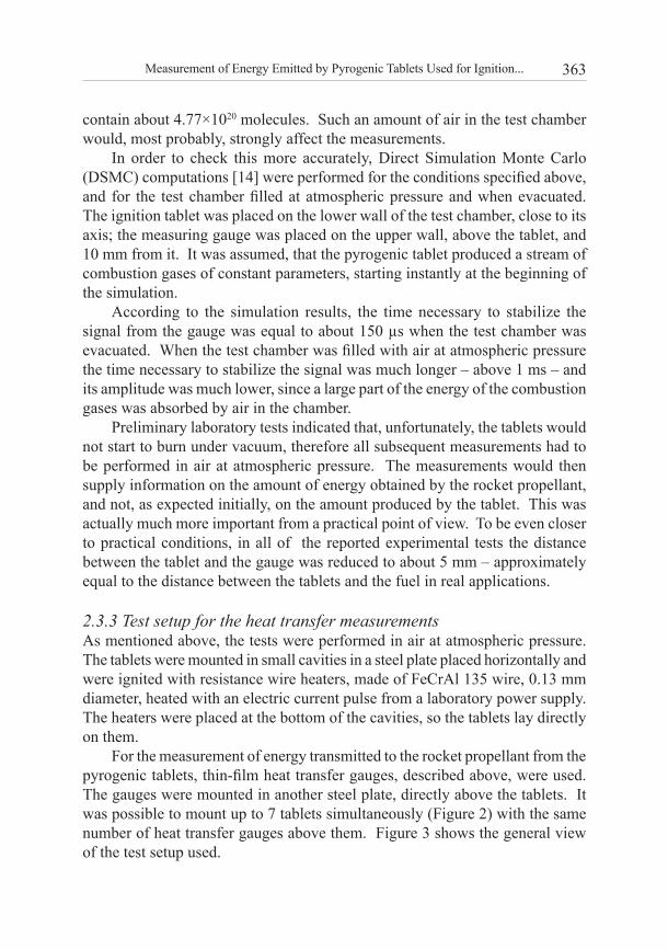
2.3.3 Test setup for the heat transfer measurementsAs mentioned above, the tests were performed in air at atmospheric pressure. The tablets were mounted in small cavities in a steel plate placed horizontally and were ignited with resistance wire heaters, made of FeCrAl 135 wire, 0.13 mm diameter, heated with an electric current pulse from a laboratory power supply. The heaters were placed at the bottom of the cavities, so the tablets lay directly on them.
For the measurement of energy transmitted to the rocket propellant from the pyrogenic tablets, thin-film heat transfer gauges, described above, were used. The gauges were mounted in another steel plate, directly above the tablets. It was possible to mount up to 7 tablets simultaneously (Figure 2) with the same number of heat transfer gauges above them. Figure 3 shows the general view of the test setup used.
364 T. Wolszakiewicz, Z.A. Walenta
Figure 2. Cavities for the pyrogenic tablets with resistance wire heaters, in the bottom plate of the test rig.
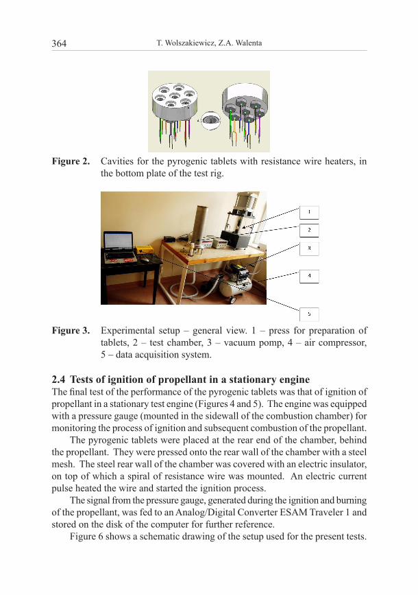
Figure 3. Experimental setup – general view. 1 – press for preparation of tablets, 2 – test chamber, 3 – vacuum pomp, 4 – air compressor, 5 – data acquisition system.
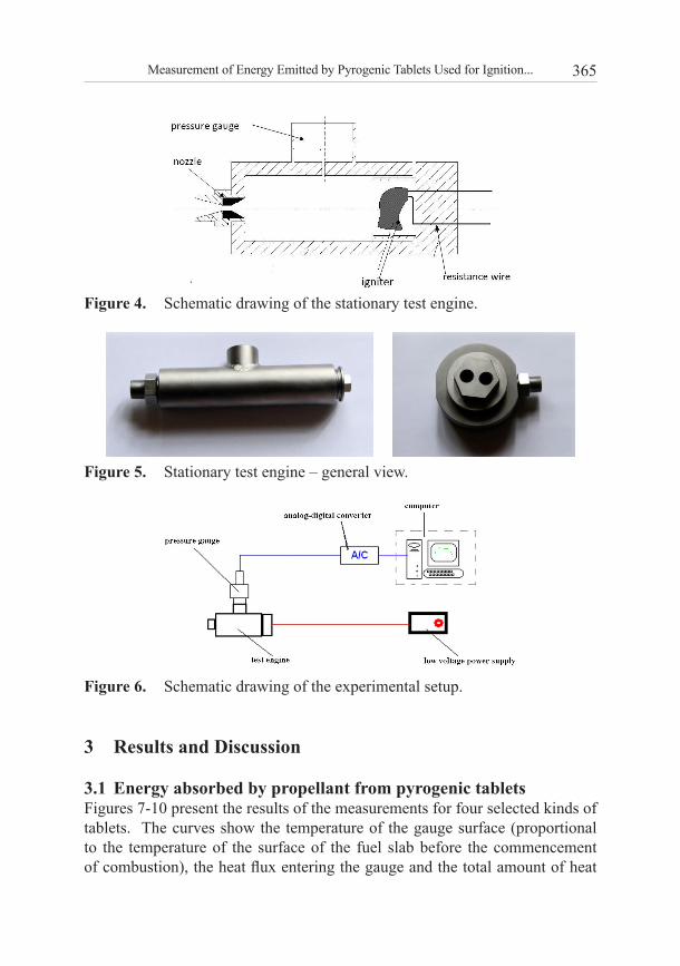
2.4 Tests of ignition of propellant in a stationary engineThe final test of the performance of the pyrogenic tablets was that of ignition of propellant in a stationary test engine (Figures 4 and 5). The engine was equipped with a pressure gauge (mounted in the sidewall of the combustion chamber) for monitoring the process of ignition and subsequent combustion of the propellant.
The pyrogenic tablets were placed at the rear end of the chamber, behind the propellant. They were pressed onto the rear wall of the chamber with a steel mesh. The steel rear wall of the chamber was covered with an electric insulator, on top of which a spiral of resistance wire was mounted. An electric current pulse heated the wire and started the ignition process.
The signal from the pressure gauge, generated during the ignition and burning of the propellant, was fed to an Analog/Digital Converter ESAM Traveler 1 and stored on the disk of the computer for further reference.
Figure 6 shows a schematic drawing of the setup used for the present tests.
365Measurement of Energy Emitted by Pyrogenic Tablets Used for Ignition...
Figure 4. Schematic drawing of the stationary test engine.
Figure 5. Stationary test engine – general view.
Figure 6. Schematic drawing of the experimental setup.
3 Results and Discussion
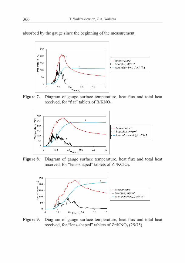
3.1 Energy absorbed by propellant from pyrogenic tabletsFigures 7-10 present the results of the measurements for four selected kinds of tablets. The curves show the temperature of the gauge surface (proportional to the temperature of the surface of the fuel slab before the commencement of combustion), the heat flux entering the gauge and the total amount of heat
366 T. Wolszakiewicz, Z.A. Walenta
absorbed by the gauge since the beginning of the measurement.
Figure 7. Diagram of gauge surface temperature, heat flux and total heat received, for “flat” tablets of B/KNO3.
Figure 8. Diagram of gauge surface temperature, heat flux and total heat received, for “lens-shaped” tablets of Zr/KClO4.
Figure 9. Diagram of gauge surface temperature, heat flux and total heat received, for “lens-shaped” tablets of Zr/KNO3 (25/75).
367Measurement of Energy Emitted by Pyrogenic Tablets Used for Ignition...
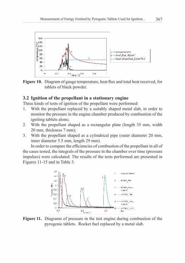
Figure 10. Diagram of gauge temperature, heat flux and total heat received, for tablets of black powder.
3.2 Ignition of the propellant in a stationary engineThree kinds of tests of ignition of the propellant were performed:1. With the propellant replaced by a suitably shaped metal slab, in order to
monitor the pressure in the engine chamber produced by combustion of the igniting tablets alone;
2. With the propellant shaped as a rectangular plate (length 35 mm, width 20 mm, thickness 7 mm);
3. With the propellant shaped as a cylindrical pipe (outer diameter 20 mm, inner diameter 5.5 mm, length 29 mm).In order to compare the efficiencies of combustion of the propellant in all of
the cases tested, the integrals of the pressure in the chamber over time (pressure impulses) were calculated. The results of the tests performed are presented in Figures 11-15 and in Table 3.
Figure 11. Diagrams of pressure in the test engine during combustion of the pyrogenic tablets. Rocket fuel replaced by a metal slab.
368 T. Wolszakiewicz, Z.A. Walenta
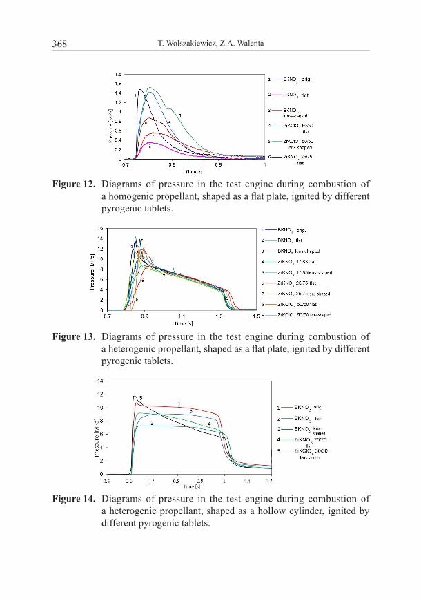
Figure 12. Diagrams of pressure in the test engine during combustion of a homogenic propellant, shaped as a flat plate, ignited by different pyrogenic tablets.
Figure 13. Diagrams of pressure in the test engine during combustion of a heterogenic propellant, shaped as a flat plate, ignited by different pyrogenic tablets.
Figure 14. Diagrams of pressure in the test engine during combustion of a heterogenic propellant, shaped as a hollow cylinder, ignited by different pyrogenic tablets.
369Measurement of Energy Emitted by Pyrogenic Tablets Used for Ignition...
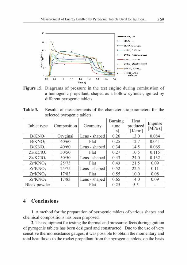
Figure 15. Diagrams of pressure in the test engine during combustion of a homogenic propellant, shaped as a hollow cylinder, ignited by different pyrogenic tablets.
Table 3. Results of measurements of the characteristic parameters for the selected pyrogenic tablets.
Tablet type Composition GeometryBurning
time [s]
Heat produced [J/cm2]
Impulse [MPa∙s]
B/KNO3 Oryginal Lens - shaped 0.26 13.0 0.084B/KNO3 40/60 Flat 0.25 12.7 0.041B/KNO3 40/60 Lens - shaped 0.34 14.5 0.065Zr/KClO4 50/50 Flat 0.27 10.5 0.115Zr/KClO4 50/50 Lens - shaped 0.43 24.0 0.132Zr/KNO3 25/75 Flat 0.43 21.5 0.09Zr/KNO3 25/75 Lens - shaped 0.52 22.5 0.11Zr/KNO3 17/83 Flat 0.55 10.0 0.08Zr/KNO3 17/83 Lens - shaped 0.65 14.0 0.09
Black powder - Flat 0.25 5.5 -
4 Conclusions
1. A method for the preparation of pyrogenic tablets of various shapes and chemical compositions has been proposed.
2. The equipment for testing the thermal and pressure effects during ignition of pyrogenic tablets has been designed and constructed. Due to the use of very sensitive thermoresistance gauges, it was possible to obtain the momentary and total heat fluxes to the rocket propellant from the pyrogenic tablets, on the basis
370 T. Wolszakiewicz, Z.A. Walenta
of the measured temperature of the gauge surface versus time. A dedicated computer program was prepared for this purpose.
3. The thermoresistance gauges, used for the tests, offered microsecond time resolution. The preliminary measurements indicated, that a resolution about two orders of magnitude lower than that was sufficient. Moreover, as followed from the DSMC simulations performed, in order to obtain the highest resolution, the tests would need to be done at initial pressures much below atmospheric pressure. However, under such conditions it was impossible to ignite the pyrogenic tablets, and, in addition, from a practical point of view, the important information was the amount of energy absorbed by the propellant under real conditions, i.e. at atmospheric pressure and not the energy emitted by the tablet. All of the reported tests were therefore performed at atmospheric pressure.
4. New engines for testing the ignition of homogenic and heterogenic propellants were designed and constructed. The propellants for testing in such an engine could be shaped as parallel-piped or hollow cylinders. A number of tests of ignition were performed, during which the magnitude of the pressure impulse was measured for both shapes of propellant, as well as for the case when the propellant was replaced by a metal slab.
5. The measured burning times of all of the tested ignition tablets remained in the range 0.25-0.56 s, and the pressure impulses 0.041-0.132 MPa. The commonly used tablets B/KNO3 burn relatively fast (0.25 s) and produce pressure impulses in the range 0.041-0.065 MPa. The longest burning times were obtained for tablets of Zr/KNO3 and the largest pressure impulses for Zr/KClO4. The heat fluxes received by the heat transfer gauge from a single tablet ranged from 13 to 24 J/cm2. The burning of the propellants, ignited by the new tablets (Zr/KNO3 and Zr/KClO4) was stable and reproducible (Figures 12-15).
6. According to the results obtained, the best material for pyrogenic tablets is the mixture Zr/KNO3, 25/75 (25% Zr, 75% KNO3). Tablets of this mixture had a long burning time (0.55-0.65 s), a large heat flux (~21 J/cm2) and the pressure impulse was close to that for tablets of B/KNO3.
7. The results obtained for Zr/KNO3 compared favourably with the classic igniter black powder, whose burning time was only 0.25 s with a heat flux of only 5.5 J/cm2.
Appendix 1
Method of measurement of the heat flux absorbed by solid propellant from pyrogenic tablets
The heat transfer gauges, used for the measurements reported in the present paper, consisted of a thin metal layer (platinum – thickness below 1 µm)
371Measurement of Energy Emitted by Pyrogenic Tablets Used for Ignition...
superimposed on a piece of an insulating substrate (glass) [13].The substrate of the gauge was flat (which is the case in the majority of
situations), its dimensions were much larger than the depth of penetration of the heat pulse during the measurement, and therefore the heat flow in the substrate may be described with the one-dimensional heat conduction equation:
( ) [ ( ) ]c kt x xθ θρ θ θ∂ ∂ ∂
⋅ =∂ ∂ ∂
(1)
with the following initial and boundary conditions:
θ(x,t) = 0 for t = 0; x > 0θ(x,t) = θw(t) for t ≥ 0; x = 0 (2)
0),(lim =+∞→
txx
θ
where: θ – temperature of the substrate; ρ – its density (constant), c = c(θ) – its specific heat;k = k(θ) – its heat conduction coefficient; t – time; x – spatial coordinate.
θw(t) is the known (measured) temperature of the gauge surface.The heat flux through unit area of the plane x = 0, (to be found) is:
0]),()[()( =
•
∂∂
−= xxtxktq θθ (3)
The parameters of the gauge substrate material (specific heat c and heat conduction coefficient k) are usually temperature dependent, and the heat conduction Equation (1) is therefore non-linear.
Introduction of a new variable:
∫=),(
0
'' )(),(tx
dktxgθ
θθ
makes it possible to reduce Equation (1) to the form:
2
2
xg
tg
∂∂
=∂∂ α (4)
where )()(θρθαck⋅
= is the “thermal diffusivity” of the substrate material.
As shown in paper [15], for materials like quartz and glass, if the temperature rise does not exceed about 150 °C, the thermal diffusivity α may be considered constant and Equation (4) in this temperature range is linear.
372 T. Wolszakiewicz, Z.A. Walenta
Now the non-dimensional variables are introduced:
0tx⋅
=α
ξ
0tt
=η
00Tkg
=ζ
(5)
and the non-dimensional heat flux:
000
0
Tq
ckt
Q•
⋅=ρ
(6)
where t0, T0, c0 and k0 are the reference values of time, temperature, specific heat and heat conductivity of the substrate material respectively.
Using Expressions (5), Equation (4) is reduced to:
2
2
ξζ
ηζ
∂∂
=∂∂
(7)
and the boundary conditions are:
ζ(ξ,η) = 0 for η = 0; ξ > 0 ζ(ξ,η) = f(η) for η ≥ 0; ξ = 0 (8)
0),(lim =+∞→
ηξζξ
where:
∫=)(
0
''
00
)(1)(ηθ
θθηw
dkTk
f (9)
The non-dimensional heat flux is expressed as:
0][ =∂∂
−= ξξζQ (10)
Applying the Laplace transformation to Equations (7)-(10) one obtains (see [16] for its derivation):
∫ −+
+=
η
λληλ
ηπ 0
'
])()0([1 dffQ (11)
373Measurement of Energy Emitted by Pyrogenic Tablets Used for Ignition...
where:
ηη
dd ff =)('
As shown in paper [17], in the temperature range considered, the heat conduction coefficient of the gauge substrate material (glass) is, with sufficient accuracy, linearly dependent on temperature:
k(θ) = k0(1 + b ∙ θ) (12)
Substitution of the above in (9) gives:
∫ ⋅+=⋅+=)(
0
2
0
''0
00
)](21)([1)1(1)(
ηθ
ηθηθθθηw
ww bT
dbkTk
f (13)
where θw = θw(η)– temperature of the gauge surface against time.
Note, that if b = 0, i.e. k(Θ) = k0 = const, there is simply 0
)()(
Tf w ηθη = .
Now, having registered the gauge surface temperature against time, it is possible to calculate the required heat flux by using Equations (13), (11) and (6), which may be transformed to:
0
000
tTck
Qq⋅⋅
=• ρ
(14)
Appendix 2
Numerical method of calculating the heat flux from the gauge surface temperature history
To calculate the heat flux from the history of the gauge surface temperature, the Equation (11) is used. Let S be the integral on the right-hand side of Equation (11):
∫ −=
η
λληλ
0
' )( dfS
The function f(η) is given in the form of a table of (N+1) points equally spaced in time. The distances between neighbouring points are equal to Δλ. The integral S may then be expressed as the sum of N integrals over the distances between the adjacent points:
374 T. Wolszakiewicz, Z.A. Walenta
......3
23
2
20
1 +−
+−
+−
= ∫∫∫∆
∆
∆
∆
∆ λ
λ
λ
λ
λ
ληλ
ληλ
ληλ dDdDdDS
λ∆−
= −1iii
ffD is the derivative (assumed constant) of the function f(λ) between
the point (i-1) and point i. Substitution of ληχ −= gives λη
λχ−
−=2dd
and the integral S takes the form:
....][23
23
2
21 +++−= ∫∫∫∆−
∆−
∆−
∆−
∆− λη
λη
λη
λη
λη
η
χχχ dDdDdDS
Integration and substitution of the values of Di and η = N.Δλ gives:
)1()(21
1 iNiNffSN
iii −−+−−
∆= ∑
=−λ
Substitution of this in Equation (11) gives finally:
)]1()(2
)0([21
1 iNiNffN
fQN
iii −−+−−+
+∆⋅
= ∑=
−λπThe last formula has been used to create the numerical program for
calculating the heat flux from the registered surface temperature history.
AcknowledgmentsFinancial support from the State Committee for Scientific Research (KBN Project ON 508 004134) is gratefully acknowledged.
5 References
[1] Gransden J.I., Taylor M.J., Study of Confined Pyrotechnic Compositions for Medium/Large Calibre Gun Igniter Applications, Propellants Explos. Pyrotech., 2007, 32, 6-11.
[2] Bhingarkar V., Singh H., Influence of Cellulosic Binders on Sensitivity and Combustion, Def. Sci. J., 2006, 56(3), 345-351.
[3] Wildegger-Gaissmaier E., Johnston I.R., Ignition of a Granular Propellant Bed, Combust. Flame, 1996, 106, 219-230.
[4] Kuwahara T., Tohara C., Ignition Characteristics of Zr/BaCrO4 Pyrolant, Propellants Explos. Pyrotech., 2002, 27, 284-289.
375Measurement of Energy Emitted by Pyrogenic Tablets Used for Ignition...
[5] Kuwahara T., Tohara C., Wang C.H., Static Electric Sensitivity Characteristics of Zr/BaCrO4 Pyrolants, Propellants Explos. Pyrotech., 2004, 29, 56-61.
[6] Lee J.S., Hsu C.K., The Effect of Different Zirconium on Thermal Behaviors for Zr/KClO4 Priming Compositions, Thermochim. Acta, 2001, 367-368.
[7] Lee J.S., Thermal Properties and Firing Characteristics of the Zr/KClO4/Viton A Priming Compositions, Thermochim. Acta, 2002, 392-393,147-152.
[8] Torecki S., Rocket Engines (in Polish: Silniki rakietowe), Warszawa, 1984. [9] Backstead M.W., Puduppakkam K., Thakre P., Yang V., Modeling of Combustion
and Ignition of Solid – Propellant Ingredients, Prog. Energy Combust. Sci., 2007, 33, 497-551.
[10] Zalewski R., Wolszakiewicz T., Experimental Studies on Fundamental Mechanical Properties of Homogeneous Solid Rocket Propellants, Przem. Chem., 2012, 91(9), 1825-1829.
[11] Zalewski R., Wolszakiewicz T., Bajkowski J., Effect of Temperature on Fundamental Mechanical Properties of Homogeneous Solid Propellants, Przem. Chem., 2012, 91(9), 1830-1833.
[12] Wolszakiewicz T., Gawor T., Zalewski R., Ballistic Analysis of Homogeneous Solid Propellants Subjected to Thermal and Mechanical Pre-loading Preliminary Communication, Przem. Chem., 2012, 91(9), 1854-1857.
[13] Hall J.G., Hertzberg A., Recent Advances in Transient Surface Thermometry, Jet Propul., 1958, 28(11), 719-723.
[14] Bird G.A., Molecular Gas Dynamics and the Direct Simulation of Gas Flows, Clarendon Press, Oxford, 1994.
[15] Hartunian R.A., Varwig R.L. On Thin Film Heat Transfer Measurements in Shock Tubes and Shock Tunnels, Phys. Fluids, 1962, 5(2), 169-174.
[16] Carslaw H.S., Jaeger J.C., Conduction of Heat in Solids, Oxford University Press, 1959.
[17] Walenta Z.A., Analogue Networks for High Heat-transfer Rate Measurements, UTIAS Technical Note, November 1964, No. 84, (AFOSR 65-0261).


![· Formula Tablets Arthritis Strength Bufferin Tablets Arthropan Liquid Arthrotec Ascodeen Ascriptin, All products Asperbuf Tablets Aspergum [chewing gum] Aspirin Asprimox Tablets](https://img.pdfslide.us/doc/110x75/5e76e2c5b6b4706c14128b70/formula-tablets-arthritis-strength-bufferin-tablets-arthropan-liquid-arthrotec-ascodeen.jpg)